1
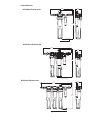
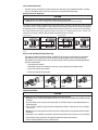
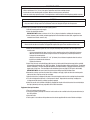
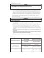
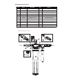
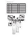
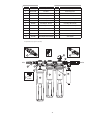
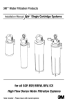
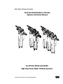
3MTM Water Filtration Products
Dual Port Manifold Water Filtration
Systems Instruction Manual
For DP1XX, DP2XX and DP3XX
High Flow Series Water Filtration Systems
Installer: Please leave this manual with owner/operator.
3M™ Water Filtration Products
Table of Contents
Safety Information........................................................................................................................................2
Warning Statements.....................................................................................................................................2
Caution/Important Notes...............................................................................................................................3
Dual Port Manifolds and Systems.................................................................................................................3
Product Dimensions.....................................................................................................................................4
Inlet and Outlet Connections.........................................................................................................................5
How to Use “Push-in” Connectors.................................................................................................................5
How to Use “Inlet/Outlet” Fitting Retention Clips............................................................................................5
Equipment Installation..................................................................................................................................5
Equipment Start-up Procedure .....................................................................................................................6
Cartridge Change-out Procedure...................................................................................................................7
Troubleshooting............................................................................................................................................7
Parts Listing.................................................................................................................................................8
Limited Warranty.........................................................................................................................................11
SAFETY INFORMATION
Read, understand, and follow all safety information contained in these instructions prior to installation. Retain
these instructions for future reference.
Intended Use:
The 3M High Flow series dual port manifold water filtration systems are intended for use in filtering potable water in
the foodservice industry and have not been evaluated for other uses. These systems are installed at the point of use
and must be installed as specified in the installation instructions.
EXPLANATION OF SIGNAL WORD CONSEQUENCES
WARNING
Indicates a potentially hazardous situation, which, if not avoided, could result in death or
serious injury and/or property damage.
CAUTION
Indicates a potentially hazardous situation which, if not avoided, may result in minor or moderate
injury and/or property damage.
CAUTION Indicates a potentially hazardous situation, which, if not avoided, may result in property damage.
WARNING
To reduce the risk associated with choking:
• Do not allow children under 3 years of age to have access to small parts during the installation of this product.
To reduce the risk associated with the ingestion of contaminants:
• Do not use with water that is microbiologically unsafe or of unknown quality without adequate disinfection
before or after the system.
To reduce the risk associated with hazardous voltage due to an installer drilling through existing electric
wiring or water pipes in the area of installation:
• Do not install near electric wiring or piping which may be in path of a drilling tool when selecting the
position to mount the filter bracket.
To reduce the risk of physical injury:
• Depressurize system as shown in manual prior to cartridge removal.
To reduce the risk associated with back strain:
• Follow safe lifting procedures.
2
CAUTION
To reduce the risk associated with property damage due to water leakage:
• Read and follow Use Instructions before installation and use of this system.
• Installation and Use MUST comply with all state and local plumbing codes.
• Protect from freezing, remove filter cartridge when temperatures are expected to drop below 40°F (4.4°C);
• Do not install on hot water supply lines. The maximum operating water temperature of this filter system is
100°F (37.8°C).
• Do not install if water pressure exceeds 125 psi (862 kPa). If your water pressure exceeds 80 psi (552 kPa), you must install a pressure limiting valve. Contact a plumbing professional if you are uncertain how to check
your water pressure.
• Do not install where water hammer conditions may occur. If water hammer conditions exist, you must install a
water hammer arrester. Contact a plumbing professional if you are uncertain how to check for this condition.
• Where a backflow prevention device is installed on a water system, a device for controlling pressure due to
thermal expansion must be installed.
• Do not use a torch or other high temperature sources near filter system, cartridges, plastic fittings or plastic
plumbing.
• On plastic fittings, never use pipe sealant or pipe dope. Use PTFE thread tape only, pipe dope properties may
deteriorate plastic.
• Take care when using pliers or pipe wrenches to tighten plastic fittings, as damage may occur if overtightening occurs.
• Do not install in direct sunlight or outdoors.
• Do not install near water pipes which will be in path of a drilling tool when selecting the position to mount
the bracket.
• Mount filter in such a position as to prevent it from being struck by other items used in the area of installation.
• Ensure that the location and fasteners will support the weight of the system when installed.
• Ensure all tubing and fittings are secure and free of leaks.
• The disposable filter cartridge MUST be replaced every 12 months, at the rated capacity or if a noticeable
reduction in flow rate occurs.
• Any non-metallic fittings used in the installations must be of adequate rating for the line pressure.
IMPORTANT NOTES
• Failure to follow instructions will void warranty.
• Allow a minimum of 3” (7.6 cm) clear space under filter to facilitate cartridge change.
• Install with the inlet and outlet ports as labeled. Make sure not to reverse connections.
• Some local codes may require the use of a licensed plumber or certified installer when disrupting a potable
water line.
High Flow Series Dual Port Manifold Water Filtration Systems
The High Flow series dual port (DP) manifold water filtration system cartridges help provide consistent high quality
water for multiple applications of cold beverages, ice, and coffee. The inlet water enters the manifolds on the left rear
side and flows through 1, 2, or 3 cartridge filters in parallel (depending upon which manifold is installed). Two separate
streams exit the manifold. One stream (on the right front side) has scale-inhibition media added from a dedicated
cartridge to reduce the ability of calcium and magnesium to precipitate as hard scale in ice machines and coffee
brewers. The other stream exits on the left side front. It supplies cold beverage dispensers and includes no scale
inhibitor. The capacity of the system is equal to the total combined flow rate and capacity ratings for the number of
cartridge filters used, regardless of the percentage of total outlet flow directed to a specific application.
3
Product Dimensions
19 1/16"
(48.4 cm)
DP1XX Water Filtration System
5 7/16"
(13.8 cm)
24 9/16"
(62.4 cm)
3" (7.6 cm) MIN
DISTANCE REQUIRED
TO REMOVE CARTRIDGE
DP2XX Water Filtration System
22 7/8"
(58.1 cm)
5 7/16"
(13.8 cm)
24 9/16"
(62.4 cm)
3" (7.6 cm) MIN
DISTANCE REQUIRED
TO REMOVE CARTRIDGE
DP3XX Water Filtration System
5 7/16"
(13.8 cm)
31 1/16"
(78.9 cm)
24 9/16"
(62.4 cm)
3" (7.6 cm) MIN
DISTANCE REQUIRED
TO REMOVE CARTRIDGE
4
Inlet and Outlet Connections
The water inlet is on the left side rear and the outlets are on both sides and are identified with labels. The fitting size is 3/4” NPT (Male). Built-in check valves (non-return) are incorporated into both outlets.
How to Use “Push-in” Connectors
CAUTION
To reduce the risk associated with property damage due to water leakage:
• Do not install unit if collet is missing. Contact your Sales Representative if collets are missing
The DP2XX & DP3XX manifolds are outfitted with a user friendly ‘Push In’ connector at the vent valve. Proper use of the
connectors is shown in the figure below. It is most important that the tubing selected for use with these connectors be
of high quality, exact size and roundness, and with no surface nicks or scratches. If it is necessary to cut the tubing,
use a plastic tubing cutter or sharp razor knife. Make a clean square cut. Should a leak occur at a "Push-In" connector, the cause may be a problem with the tubing and new tubing may be required.
To Attach Tubing
Push tubing straight in as far as it
will go
To Release Tubing
Tubing is secured in.
Push in collet to release tubing.
Pull tubing straight out.
How to Use the Inlet/Outlet Fitting Retention Clips
This product is outfitted with inlet/outlet fittings. The fittings can be attached or removed from the system without tools. Retention clips are semi-circular in shape with three internal tabs, bottom, center and top. Tab interlaces
with windows in the manifold head near each connection port. Clip is flexible and easily assembled following these
instruction and illustrations.
1. Insert fitting into manifold.
2. With fitting inserted into manifold port, snap clip into place beginning at the bottom window
3. Push center tab into center window.
4. Finally push top tab into top window.
Step 1
Step 2
Step 3
Step 4
Equipment Installation
CAUTION
To reduce the risk associated with property damage due to water leakage:
• Do not use a torch or other high temperature sources near filter system, cartridges, plastic fittings or plastic
plumbing.
• On plastic fittings, never use pipe sealant or pipe dope. Use PTFE thread tape only, pipe dope properties may
deteriorate plastic.
• Take care when using pliers or pipe wrenches to tighten plastic fittings, as damage may occur if overtightening occurs.
• Do not install near water pipes which will be in path of a drilling tool when selecting the position to mount
the system.
• Mount filter in such a position as to prevent it from being struck by other items used in the area of installation.
• Ensure that the location and fasteners will support the weight of the system when installed.
• Ensure all tubing and fittings are secure and free of leaks.
5
IMPORTANT NOTES
• Failure to follow instructions will void warranty.
• Allow a minimum of 3 in. (7.6 cm) clear space under filter to facilitate cartridge change.
• Install with the inlet and outlet ports as labeled. Make sure not to reverse connections.
• Some local codes may require the use of a licensed plumber or certified installer when disrupting a potable water line.
CAUTION
To reduce the risk associated with property damage due to water leakage:
• Any non-metallic fittings used in the installations must be of adequate rating for the line pressure.
Manifolds may be used with metal or non-metallic piping systems.
1. Shut off incoming cold water supply.
2. Select the installation location.
IMPORTANT NOTE: Allow a minimum of 3 in (7.6 cm) of space below the cartridges for change-outs.
3. Select fasteners (not included) and tools appropriate for the installation location (wall, support structure mounted to wall studs, concrete, etc.) CAUTION
To reduce the risk associated with property damage due to water leakage:
• Ensure that the location and fasteners will support the weight of the system when installed and full of water.
4. Mount the manifold/filter system to a wall using the mounting holes provided on the back plate of the metal bracket.
• It is recommended to first draw a level line on the mounting surface at the height of the fasteners. • Mark the location of the fasteners using the bracket as a template or by measuring the distance between the mounting holes.
• Install the fasteners and allow 1/4”- 3/8” (6-10 mm) of each fastener to protrude from the surface. •Install the manifold onto the fasteners.
•Tighten the fasteners.
5. Install inlet (left rear) and outlet fittings (right front to ice/coffee and left front to beverage) to the manifold. All connections terminate with a 3/4” NPT (male) fitting. The inlet kit includes a fitting and a ball valve. The left front outlet is a fitting only. The kit for the right side outlet to ice includes the fitting, a stainless-steel filter head, two (2) nipples and a check valve. The instructions for the installation clips are on page 5 (PTFE tape is not included).
IMPORTANT NOTES: Be sure to install the stainless steel fitting head with the flow arrow. 6.Remove the sanitary caps from the water filter cartridges, and apply a light coat of water or water-grade lubricant to the o-rings on each of the cartridges.
7.Align the tabs of the cartridge with the slots in the retaining plate and insert the cartridge into the manifold. 8.Turn the cartridge to the right until a clicking sound is heard. Repeat for the remaining cartridges; the clicking sound indicates the cartridge is properly engaged.
9. Install the smaller scale inhibitor cartridge by engaging the threads in the stainless steel tee and rotating to the right (clockwise) until snug, regardless of final label orientation.
Equipment Start-up Procedure
1. Turn on incoming water to system.
2. Pressurize system by rotating the inlet ball valve handle on the manifold to the left (counterclockwise) to the “ON” position.
3. Check for leaks.
4. Flush system in accordance with performance data sheet supplied with the water filtration cartridges.
6
Cartridge Change-out Procedure
CAUTION
To reduce the risk associated with property damage due to water leakage:
• Read and follow Use Instructions before installation and use of this system.
• The disposable filter cartridge MUST be replaced every 12 months, at the rated capacity or if a noticeable
reduction in flow rate occurs.
The water filter cartridges will need to be changed every 6-12 months, at the rated capacity, or when low
pressure in indicated on the manifolds pressure gauge, whichever occurs first. Depending on local water
quality, you may need to change the cartridges prior to the recommended change-out. The loss of flow to
carbonators or improper fill at the ice maker are also indicators that the cartridges will need to be replaced
1. Shut off the inlet water by rotating inlet ball valve 1/4 turn to the left (clockwise) on manifold to the “OFF” position.
2. Depressurize system. Use plastic tubing and vent valve for DP2XX and DP3XX manifolds. There is no vent valve on DP1XX manifold.
3. Push tab to release cartridge locking mechanism while simultaneously rotating cartridge slightly to the left.
WARNING
To reduce the risk associated with back strain:
• Follow safe lifting procedures.
4. Using both hands and holding cartridge from the bottom, rotate the cartridge a quarter turn to the left and gently pull down.
IMPORTANT NOTE: A small amount of water will drain from manifold as cartridge is removed.
5. Remove the sanitary caps from the water filter cartridges, and apply a light coat of water or water-grade lubricant to the o-rings on each of the cartridges. Align the tabs of the cartridge with the slots in the
retaining plate and insert the cartridge into the manifold. Turn the cartridge to the right until a clicking
sound is heard. Repeat for the remaining cartridges; the clicking sound indicates the cartridge is properly
engaged.
6. Slowly turn the inlet water ball valve on the manifold to the left (counterclockwise) to the ON position, and check for leaks.
7. Install the smaller scale inhibitor cartridge by engaging the threads in the stainless steel tee and rotating to the right (clockwise) until snug, regardless of final label orientation. 8. Flush system in accordance with performance data sheet supplied with the water filtration cartridges.
Troubleshooting
No water flow through system
Not enough water to
downstream application
Short filter life
Inlet valve closed
Check shut-off valve position
Filters clogged
Replace filter cartridge(s)
Low incoming water pressure
Check source
Filters clogged
Replace filter cartridge(s)
Temporarily dirty water
Change cartridges or install an
additional upstream pre-filter
7
DP1XX Replacement Parts Listing
Item
Part no.
Description
Qty*
Function
1
6228603
DP1XX Single Manifold
1
Assembly, complete
2
See catalog
Replacement Cartridge
1
Water filtration
3
8500556
Pressure gauge
1
Monitor outlet water pressure
4
85-8528
Clip
1
Retain inlet/outlet fittings
5
63597320
o-ring
1
Seal inlet/outlet fittings
6
6225008
Inlet fitting kit –left rear
1
Inlet fitting with ball valve
7
6225006
Outlet fitting kit – left front
1
Beverage outlet fitting
8
6225007
Outlet fitting kit – right front
1
Ice/Coffee outlet fitting
9
60-235280
¾” Female NPT ball valve
1
Inlet water shut-off
10
5617501
Retainer kit
1
Secure cartridges
11
5582106
HF8-S Replacement Cartridge
1
Scale inhibitor
*Per part number, not per system or assembly.
6
Rear
3
4
8
Front
5
5
Outlet
Inlet
7
10
1
9
Front
Outlet
11
2
8
DP2XX Replacement Parts Listing
Item
Part no.
Description
Qty*
Function
1
6228503
DP2XX Twin Manifold
1
Assembly, complete
2
60-2333700
Vent Valve
1
Release trapped air
3
See catalog
Replacement Cartridges
1
Water filtration
4
8500556
Pressure gauge
1
Monitor outlet water pressure
5
85-8528
Clip
1
Retain inlet/outlet fittings
6
63597320
o-ring
1
Seal inlet/outlet fittings
7
6225005
Inlet fitting kit –left rear
1
Inlet fitting with ball valve
8
6225006
Outlet fitting kit – left front
1
Beverage outlet fitting
9
6225007
Outlet fitting kit – right front
1
Ice/Coffee outlet fitting
10
60-235280
¾” Female NPT ball valve
1
Inlet water shut-off
11
5617501
Retainer kit
1
Secure cartridges
12
5582106
HF8-S Replacement Cartridge
1
Scale inhibitor
*Per part number, not per system or assembly.
4
5
Rear
7
9
Front
6
Outlet
Inlet
6
10
11
1
2
3
8
Front
Outlet
3
9
12
Item
Part no.
Description
Qty*
Function
1
6228403
DP3XX Triple Manifold
1
Assembly, complete
2
60-2333700
Vent Valve
1
Release trapped air
3
See catalog
Replacement Cartridges
1
Water filtration
4
8500556
Pressure gauge
1
Monitor outlet water pressure
5
85-8528
Clip
1
Retain inlet/outlet fittings
6
63597320
o-ring
1
Seal inlet/outlet fittings
7
6225005
Inlet fitting kit –left rear
1
Inlet fitting with ball valve
8
6225006
Outlet fitting kit – left front
1
Beverage outlet fitting
9
6225007
Outlet fitting kit – right front
1
Ice/Coffee outlet fitting
10
60-235280
¾” Female NPT ball valve
1
Inlet water shut-off
11
5617501
Retainer kit
1
Secure cartridges
12
5582106
HF8-S Replacement Cartridge
1
Scale inhibitor
*Per part number, not per system or assembly.
7
5
Rear
4
9
Front
6
Outlet
Inlet
10
6
11
1a
3
7
Front
Outlet
3
3
10
2
12
Limited Warranty
3M Purification Inc. warrants DP1XX, DP2XX, DP3XX High Flow series water filtration systems only to be free from defects in material
and workmanship for five (5) years from the date of purchase. The disposable filter cartridge is warranted from defects in material
and workmanship for a period of one (1) year from the date of purchase. This warranty does not cover failures resulting from abuse,
misuse, alterations or damage not caused by 3M Purification Inc. or failure to follow installation and use instructions. No warranty is
given as to the service life of any filter cartridge or membrane as it will vary with local water conditions and consumption. 3M PU-
RIFICATION INC. MAKES NO OTHER WARRANTIES OR CONDITIONS, EXPRESS OR IMPLIED, INCLUDING, BUT NOT LIMITED
TO, ANY IMPLIED WARRANTY OR CONDITION OF MERCHANTABILITY OR FITNESS FOR A PARTICULAR PURPOSE OR ANY
IMPLIED WARRANTY OR CONDITION ARISING OUT OF A COURSE OF DEALING, CUSTOMER OR USAGE OF TRADE. If the
Product fails to satisfy this Limited Warranty during the warranty period, 3M Purification Inc., at it’s option, will replace the Product
or refund your Product purchase price. This warranty does not cover labor. The remedy stated in this paragraph is Customer’s
sole remedy and 3M Purification Inc.’s exclusive obligation.
This warranty gives you specific legal rights, and you may have other rights which may vary from state to state, or country to country.
For any warranty questions, please call 866.990.9785 or mail your request to: Warranty Claims, 3M Purification Inc., 400 Research
Parkway, Meriden, CT 06450. Proof of purchase (original sales receipt) must accompany the warranty claim, along with a complete
description of the Product, model number and alleged defect.
Limitation of Liability: 3M Purification Inc. will not be liable for any loss or damage arising from this 3M Purification Inc. product,
whether direct, indirect, special, incidental, or consequential, regardless of the legal theory asserted, including warranty, contract,
negligence or strict liability. Some states and countries do not allow the exclusion or limitation of incidental or consequential damages, so the above limitation or exclusion may not apply to you.
11
Important Notice
The information described in this literature is accurate to the best of our knowledge. A variety of factors, however, can affect
the performance of the Product(s) in a particular application, some of which are uniquely within your knowledge and control.
INFORMATION IS SUPPLIED UPON THE CONDITION THAT THE PERSONS RECEIVING THE SAME WILL MAKE THEIR OWN
DETERMINATION AS TO ITS SUITABILITY FOR THEIR USE. IN NO EVENT WILL 3M PURIFICATION INC. BE RESPONSIBLE FOR
DAMAGES OF ANY NATURE WHATSOEVER RESULTING FROM THE USE OF OR RELIANCE UPON INFORMATION.
It is your responsibility to determine if additional testing or information is required and if this product is fit for a particular purpose
and suitable in your specific application.
3M Purification Inc.
400 Research Parkway
Meriden, CT 06450 U.S.A.
Tel: 866.990.9785
203.237.5541
Fax: 203.238.8701
www.3Mfoodservice.com
www.3Mpurification.com
3M is a trademark of 3M Company.
© 2012 3M Company. All rights reserved.
INSTR4325 0912B
Please Recycle. Printed in U.S.A.
12