1
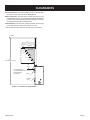
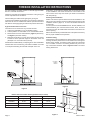
EMPIRE
INSTALLATION Instructions
AND Owner's Manual
Comfort Systems
Deluxe Vent-Free Universal Fireboxes
GAS-FIRED
UNIVERSAL FIREBOX FOR
ALL VENT-FREE LOG SETS
MODELS
VFD32FB0L-3
VFD36FB0L-3
VFD42FB0L-3
VFD32FB2ML-5
VFD36FB2ML-5
VFD42FB2ML-5
VFD32FB0F-3
VFD36FB0F-3
VFD42FB0F-3
VFD32FB2MF-5
VFD36FB2MF-5
VFD42FB2MF-5
VFD32FB2AL-3
VFD36FB2AL-3
VFD42FB2AL-3
VFD32FB2AF-3
VFD36FB2AF-3
VFD42FB2AF-3
VFD32FB3MF-5
VFD36FB3MF-5
VFD42FB3MF-5
ANSI Z21.91 Ventless Fireplace Enclosures for Gas Fired
Decorative Type Unvented Room Heaters
WARNING: If the information in these instructions are not
followed exactly, a fire or explosion may result causing
property damage, personal injury or loss of life.
— Do not store or use gasoline or other flammable vapors
and liquids in the vicinity of this or any other appliance.
—WHAT TO DO IF YOU SMELL GAS
• Do not try to light any appliance.
• Do not touch any electrical switch; do not use any
phone in your building.
• Immediately call your gas supplier from a neighbor’s phone. Follow the gas supplier’s instructions.
• If you cannot reach your gas supplier, call the fire
department.
— Installation and service must be performed by a qualified installer, service agency or the gas supplier.
Do not attempt to modify or alter the construction of the firebox or its components. Any modification or alteration of construction may void
the warranty of this firebox.
Children and adults should be alerted to the
hazards of high surface temperature and
should stay away to avoid burns or clothing ignition.
Installer: Leave this manual with the appliance.
Consumer: Retain this manual for future reference.
For use only with a listed gas-fired
unvented decorative room heater not to exceed 40,000 btu/h.
Do not build a wood fire.
WARNING:
Improper installation, adjustment, alteration, service or maintenance can cause injury or property
damage. Refer to this manual. For assistance or additional
information, consult a qualified installer, service agency or
the gas supplier.
Carefully review the instructions supplied with the decorative type unvented room heater for the minimum fireplace
size requirement.
DO NOT INSTALL a vent-free log set IN THIS FIREBOX,
UNLESS THIS FIREBOX MEETS THE MINIMUM DIMENSIONS
REQUIRED FOR THE INSTALLATION.
Young children should be carefully supervised
when they are in the same room as the firebox.
Page 1
TABLE OF CONTENTS
SECTIONPAGE
IMPORTANT SAFETY INFORMATION............................................................................. 3
INTRODUCTION............................................................................................................... 3
CLEARANCES.............................................................................................................. 4 - 5
FIREBOX INSTALLATION INSTRUCTIONS................................................................ 6 - 8
INSTALLING HOOD..................................................................................................... 8 - 9
GAS LINE CONNECTION................................................................................................. 9
OPTIONAL FRESH AIR KIT INSTALLATION INSTRUCTIONS............................... 10 - 12
OPTIONAL FBB5 SINGLE SPEED BLOWER INSTALLATION INSTRUCTIONS.... 13 - 15
JUNCTION BOX WIRING INSTALLATION INSTRUCTIONS.......................................... 16
MAINTENANCE............................................................................................................... 16
MASTER PARTS DISTRIBUTOR LIST........................................................................... 17
HOW TO ORDER REPAIR PARTS.................................................................................. 17
PARTS LIST..................................................................................................................... 18
PARTS VIEW................................................................................................................... 19
ACCESSORIES........................................................................................................ 20 - 21
WARRANTY..................................................................................................................... 22
APPLIANCE SERVICE HISTORY................................................................................... 23
Page 2
33637-2-0215
IMPORTANT SAFETY INFORMATION
The installation must conform with local codes or, in
the absence of local codes, with the National Fuel Gas
Code, ANSI Z223.1 (latest edition) and to the National
electrical Code, ANSI/NFPA70 (latest edition).
NOTE: Installation and repair should be done by a qualified service person. The appliance should be inspected
before use and at least annually by a qualified service
person. More frequent cleaning may be required due
to excessive lint from carpeting, bedding material, etc.
It is imperative that control compartment, burners and
circulating air passageways of the appliance be kept
clean.
This Empire Comfort Systems, Inc. firebox and its
components have been tested and will operate safely
when installed in accordance with this installation
manual. Read all instructions before starting installation,
then follow these instructions carefully during
installation to maximize firebox benefit and safety.
Report to your dealer any parts damaged in shipment.
The Empire Comfort Systems, Inc. warranty will be
voided by, and Empire Comfort Systems, Inc. disclaims
any responsibility for the following actions:
- Installation of any damaged firebox.
- Modification of the firebox or any of the components
parts thereof.
- Installation other than as instructed by Empire
Comfort Systems, Inc.
Any safety screen or guard removed for servicing an
appliance must be replaced prior to operating the appliance. Provide adequate combustion and ventilation air.
The flow of combustion and ventilation air MUST NOT
be obstructed.
Provide adequate clearance around air openings into
the combustion chamber and adequate accessibility
clearance for servicing and proper operation. NEVER
obstruct the front opening of the appliance.
- Installation and/or use of any component part
or accessory not approved by Empire Comfort
Systems, Inc. in combination or assembly with
a Empire Comfort Systems, Inc. firebox, not
withstanding any independent testing laboratory
or other third party approval of such component
part or accessory.
Any such action may create a possible fire hazard.
Consult your local building codes.
Firebox Screen.
The firebox screen must be in place when the firebox
is operating.
INTRODUCTION
Instructions to Installer
1. Installer must leave instruction manual with owner after
installation.
2. Installer must have owner fill out and mail warranty card
supplied with firebox.
3. Installer should show owner how to start and operate
log set that is installed into firebox.
Important
All correspondence should refer to complete Model Number,
Serial Number.
Notice: During initial firing of this firebox with a log set
installed, its paint will bake out, and smoke will occur. To
prevent triggering of smoke alarms, ventilate the room in
which the unit is installed.
Qualified Installing Agency
Installation and replacement of gas piping, gas utilization
equipment or accessories and repair and servicing of
equipment shall be performed only by a qualified agency.
The term "qualified agency" means any individual, firm,
corporation or company which either in person or through
a representative is engaged in and is responsible for (a)
33637-2-0215
the installation or replacement of gas piping or (b) the
connection, installation, repair or servicing of equipment,
who is experienced in such work, familiar with all precautions
required and has complied with all the requirements of the
authority having jurisdiction.
State of Massachusetts: The installation must be made
by a licensed plumber or gas fitter in the Commonwealth
of Massachusetts. The state of Massachusetts requires
that a flexible appliance connector cannot exceed three
feet in length.
Sellers of unvented propane or natural gas-fired
supplemental room heaters shall provide to each
purchaser a copy of 527 CMR 30 upon sale of the unit.
In the State of Massachusetts, unvented propane and
natural gas-fired space heaters shall be prohibited in
bedrooms and bathrooms.
The installation must conform with local codes or, in the
absence of local codes, with the National Fuel Gas Code,
ANSI Z223.1/NFPA 54.*
*Available from the American National Standards Institute,
Inc., 11 West 42nd St., New York, N.Y. 10036.
Page 3
CLEARANCES
Sidewall Clearances: The clearance from the inside of the firebox
to perpendicular combustible side wall should not be less than
6 inches. See Figure 1.
Firebox Side and Back Clearances: The firebox outer casing side
and back flanges are zero clearance to combustibles.
COMBUSTIBLE
FINISHED WALL
OR MANTEL
2X4
HEADER
FINISHED WITH
TRIM KIT OR
NON-COMBUSTIBLE
MATERIAL
Top Framing and Finishing: Combustible finishing materials
requires 3/4 inch to top of unit. See Figure 2.
3/4" GAP REQUIRED
COMBUSTIBLE
MATERIALS ALLOWED
IN SHADED AREAS
FIREBOX
(TOP VIEW)
FRONT FACE (SIDE)
3"
MAX.
Figure 2a - Louvered Models
45°
6"
PERPENDICULAR
SIDE WALL
COMBUSTIBLE
FINISHED WALL
OR MANTEL
Figure 1
2X4
HEADER
3/4" GAP REQUIRED
Figure 2b - Flush Models
Page 4
33637-2-0215
CLEARANCES
Ceiling Clearances: The ceiling height should not be less than
42 inches from the top of the hood. See Figure 3.
Mantel Clearances: Vent free firebox models must use the hood
supplied with the firebox, or one of the optional hood kits available
for each model. If a combustible mantel is installed, it must meet
the clearance requirements detailed below.
Grate Clearance: The minimum clearance between the front legs
of the grate and front edge of the firebox is 2 inches.
Leave at least 36 inches clearance from the front of the firebox.
CEILING
12”
MAX
10”
MANTEL
21”
10” 8” COMBUSTIBLES
ALLOWED
18 1/2”
6 ½”
16 1/2”
13”
5”
14 1/2”
3 ½”
12 1/2”
84”
MIN.
(CEILING TO FLOOR)
2”
10 1/2”
3/4”
9”
8”
MIN.
3/4” COMBUSTIBLE
CLEARANCE REQUIRED
T
FROM TOP
EDGE
OF FIREBOX
HOOD
FIREBOX
FACE
Figure 3 - Clearances to Combustibles
33637-2-0215
Page 5
FIREBOX INSTALLATION INSTRUCTIONS
Any vent-free Gas Log Heater must be “For use with approved ANSI
Z21.11.2 unvented room heater.”
Follow and complete the installation instructions of the gas log set
and the requirements of this firebox.
Check all fittings for leaks before lighting the gas log set.
In planning the installation for the firebox, it is necessary to determine
where the unit is to be installed and whether optional accessories
are desired. Gas supply piping should also be planned at this time.
A gas shut off must be in this line.
The firebox can be mounted on any of these surfaces:
1. A flat hard combustible or non-combustible surface.
2. A raised platform of combustible or non-combustible material.
3. Recessed into the floor as illustrated by Figure 4 (flush face),
and Figure 5 (louvered models).
4. Supported under all four corners of the firebox so that contact
is made on all four perimeter edges on the bottom of the unit
(Example: Four concrete masonry blocks).
If the firebox is installed directly on carpeting, tile or other combustible
material other than wood flooring, it should be installed on a metal
or wood panel extending the full width and depth of the unit.
At this point, you should have decided what components to include
in your installation, and where the firebox is to be located. If this
has not been done, stop and consult your dealer for assistance
with this planning.
Planning Your Installation
Please note that the optional VFA2 Fresh Air kit available for use
with the Vent Free Firebox must be installed at the time of the initial
installation. Refer to pages 10, 11 and 12 for detailed instructions
for the air kit.
Accessory kits such as the FBB5 Blower kit, Trim kits, Mantels, Full
Cabinet Mantels, plus other Decorative Frame, Hood, and Door
accessory kits may be installed after the firebox is secured to the
framed opening.
Refer to the instructions provided with each of the optional accessory
kits for proper installation and operation.
Firebox Framing
Firebox framing can be built before or after the firebox is set in place.
Framing should be positioned to accommodate wall covering and
firebox facing material. The firebox framing should be constructed
of 2 x 4 lumber or heavier. The framing headers may rest on the
top of the firebox standoffs. Refer to Figures 6 and 7 for firebox
framing dimensions.
LOUVERED
FIREBOX
MODELS
COMBUSTIBLE MATERIALS ALLOWED
Figure 5
Figure 4
Deluxe Vent-Free Firebox Framing Dimensions (in inches)
A
B
C
Framing Height
Framing Width
Framing Depth
VFD32FB
33 3/4
35 1/2
16 1/4
VFD36FB
35 3/4
40 1/2
18 3/4
VFD42FB
35 3/4
44 1/2
18 3/4
Model
Attention: Add 3-3/4 inches to "A" Dimension when using flush mantel base.
Page 6
Figure 6
33637-2-0215
FIREBOX INSTALLATION INSTRUCTIONS
OUTER FIREBOX DIMENSIONS
DELUXE
LOUVERED
G
I
A
G
DELUXE
FLUSH
J
I
A
J
H
N
N
H
K
F
B
K
F
B
C
D
L
M
INNER FIREBOX DIMENSIONS
B
E
D
SIDE VIEW
TOP VIEW
A
C
INNER FIREBOX DIMENSIONS (in inches)
OUTER FIREBOX DIMENSIONS (in inches)
INDEX
LETTER
VFD32
LOUVERED
VFD36
VFD42
VFD32
FLUSH
VFD36
VFD42
A
33
35
35
33
35
35
B
35
40
44
35
40
44
C
16 1/2
19
19
16 1/2
19
19
D
27 7/8
31 7/8
35 7/8
27 7/8
31 7/8
35 7/8
F
31
36
40
31
36
40
G
22 1/4
24 1/4
24 1/4
22 1/4
24 1/4
24 1/4
H
1 3/16
1 3/16
1 3/16
6 1/8
6 1/8
6 1/8
I
28 3/8
30 3/8
30 3/8
28 3/8
30 3/8
30 3/8
J
8 5/16
8 5/16
8 5/16
8 5/16
8 5/16
8 5/16
K
4 3/4
4 3/4
4 3/4
4 3/4
4 3/4
4 3/4
L
35
39 3/8
41 3/8
35
39 3/8
41 3/8
M
60 1/16
68 13/16
72 13/16
60 1/16
68 13/16
72 13/16
N
2 11/16
2 11/16
2 11/16
2 11/16
2 11/16
2 11/16
INDEX
LETTER
VFD32
VFD36
VFD42
WITHOUT BRICK
A
31
36
40
B
25 3/16
29 3/16
33 3/16
C
14 1/8
16 1/2
16 1/2
D
18 11/16
20
20
E
22
24
24
WITH BRICK
A
29 5/16
34 5/16
38 5/16
B
24
28
32
C
13 5/16
15 3/4
15 3/4
D
18 11/16
20
20
E
22
24
24
Figure 7
Firebox Dimensions
33637-2-0215
Page 7
FIREBOX INSTALLATION INSTRUCTIONS
Locating Firebox
Place firebox in framing opening. Use the tabs on the side of the
firebox to attach firebox to framing. Different tab locations can be
used for finishing materials with thicknesses of 1/2 inch and 5/8 inch.
See Figure 8.
Framing tabs should fit directly against framing material. Use at
least one nail per bracket to secure in place.
Check squareness of the firebox prior to securing to framed opening.
See Figure 9.
Figure 9
Figure 8
INSTALLING HOOD
A black hood that is furnished with each firebox (or optional hood)
MUST be installed before the firebox is used. Failure to do so
may create a possible fire hazard. The hood is located behind
upper louver, or inside the firebox on flush face units. If brass,
stainless steel, or hammered pewter hoods are desired, they can
be purchased as an option. Attachment is the same as the standard
black hood.
Flush Face Models
Flush Face Models
1. On flush face models, loosen the two screws (A) holding firebox
top to face panel, then slide the hood flange between the firebox
top and face panel and re-tighten the screws.
A
C
A
C
INNER FIREBOX TOP
2. Install one screw at each end of the hood as shown (C).
Louvered Models
1. If you have a louvered model, remove upper louver.
2. Place the top hood flange on top of the firebox, then install three
screws through the firebox top from below and screw into the
pilot holes in the hood flange (B).
3. Install one screw at each end of the hood as shown (C).
4. Re-install louver.
B
Caution: The hood must be installed prior to operation of appliance.
See Figure 10
C
Louvered Models
Figure 10
Page 8
33637-2-0215
INSTALLING HOOD
Extended Hoods
If your non-combustible facing material is over 1" in thickness that will be used to finish this firebox, an extended hood is available that will
extend out 2" farther out into the room. Contact your local dealer for details.
VB4H32BL
Standard Black
VB4H36BL
Standard Black
VB4H42BL
Standard Black
VB4H32BR
Polished Brass
VB4H36BR
Polished Brass
VB4H42BR
Polished Brass
VB4H32SS
Stainless Steel
VB4H36SS
Stainless Steel
VB4H42SS
Stainless Steel
VB4H32HP
Hammered Pewter
VB4H36HP
Hammered Pewter
VB4H42HP
Hammered Pewter
Finishing
All joints (top, bottom and sides), where the wall or decorative facing material meets the firebox surround should be sealed with a noncombustible material.
Hearth extensions are recommended, but not required for these fireboxes.
GAS LINE CONNECTION
The firebox is designed to accept a 3/8-inch gas line for an approved
vent-free gas logset. Have the line installed by a qualified service
person in accordance with all building codes. Consult local building
codes to properly size the gas supply line leading to the 3/8-inch
hook-up at the unit. The state of Massachusetts requires that a
flexible appliance connector cannot exceed three feet in length.
Gas access holes are provided on both sides of the firebox. See
Figure 11. On models with refractory brick panels installed,
carefully remove the knockout in the refractory brick panel using a
large standard screwdriver and hammer. First, place screwdriver in
groove next to plug and pry sideways to pop out main plug. Then
remove the remaining concrete in hole with gentle tapping with ball
peen hammer and/or screwdriver. A masonry drill and bit may also
be used to create a clean hole for the gas line to pass through.
See Figure 12.
GAS ACCESS HOLES
When installing optional ceramic fiber side panels into firebox,
lay panel on a flat surface. Remove the gas line knockout (round
depression) in the appropriate side panel using a drill or utility knife.
After the brick panel knockout is removed, the firebox wrap may
have a round metal knockout that must be removed also. Use a
screwdriver to punch out the metal knockout.
Figure 11
Check gas type. Use only the gas type indicated on the gas log
set rating plate. If the gas listed on the plate is not your type of gas
supply, DO NOT INSTALL. Contact your dealer for proper model.
Always use an external regulator for all LP fireboxes to reduce the
supply tank pressure to a maximum of 14 inch w.c. This is in addition
to the regulator fitted to the log set.
WARNING: CONNECTION DIRECTLY TO AN UNREGULATED
L.P. TANK CAN CAUSE EXPLOSION.
Install only a ANSI Z21.11.2 vent-free log set into this firebox.
Brick Panel
Figure 12
33637-2-0215
Page 9
OPTIONAL FRESH AIR KIT INSTALLATION INSTRUCTIONS
The optional Fresh Air Kit is designed to introduce outside air to
the firebox as desired. It must be installed prior to, or at the time of firebox installation to
framing.
The Fresh Air kit must be installed prior to the installation of wallboard or other finishing materials around the unit.
Hardware needed (not provided): 4 inch Aluminum Flex Duct,
2 Band Clamps
Tools needed:Gloves, Metal snips, 5/16 inch Nut Driver, Phillips Screwdriver
Caution:
Sharp edges
Slide Assembly Installation
1. Begin by removing the rectangular cutout located on the left
side of the unit. Use gloves and sheet metal snips to create
the opening for the Air Door assembly to install into. See Figure 13.
Figure 15
Figure 13
2. Bend the tab out of the way. See Figure 14.
Figure 16
4. Fasten the Handle Retainer to the firebox side with two
10 x 1/2 Phillips Truss Head Screws as shown in Figure 16.
Figure 14
3. Insert Slide Assembly through the cut-out as shown in Figure
15. Before you fasten ensure that the handle penetrates the
inner firebox wall. See Figure 16. Fasten the Slide Assembly
with the four 10 x 1/2 Hex Head Screws provided.
Page 10
33637-2-0215
OPTIONAL FRESH AIR KIT INSTALLATION INSTRUCTIONS
5. Push the handle for Open position and pull the handle for the
Closed position. See Figure 17.
CLOSED
OPEN
Completion of Air Kit installation
1. Determine the length of 4 inch diameter rigid or flex duct connector (installer supplied) you will need from the firebox/fireplace to the exterior surface of the outside wall, where the air
kit hood will be installed. Add a few extra inches to the length
to allow for easier attachment of the outside duct connection
prior to securing the outside rain cap hood to the building.
2. Secure the 4 inch diameter duct to the Slide Assembly collar
on the firebox with band clamps or screws (installer supplied).
3. Run the other end of the duct through the exterior wall cutout.
4. From the outside of the building, connect the duct to the collar
on the outside air vent assembly with band clamp or screws
to secure (installer supplied).
5. Secure the Outside Air Vent Assembly to the outside wall with
the four 10 x 1 1/2 Hex Head Slotted Screws provided. Seal
with caulk as necessary. See Figure 18.
6. Figure 19 illustrates the various options for installation of the
air duct run possibilities.
Note: In installations where the flex duct would normally be
straight (without turns), it is recommended a turn or dip
be added in the run to reduce air velocity.
CAULKING
OUTSIDE
AIR VENT ASSY
Figure 17
WALL
Caulk and Install Duct Termination
Figure 18
Figure 19
33637-2-0215
Page 11
OPTIONAL FRESH AIR KIT INSTALLATION INSTRUCTIONS
1
2
3
PARTS LIST
INDEX NO.
PART NO.
DESCRIPTION
1
29259
Outside Air Vent Assembly
2
29257
Slide Assembly
3
29263
Handle Retainer
Hardware Pack
Page 12
33637-2-0215
OPTIONAL FBB5 SINGLE SPEED BLOWER INSTALLATION INSTRUCTIONS
Attention: Install blower assembly before connecting gas inlet
supply line.
Wiring
The appliance, when installed, must be electrically grounded in
accordance with local codes or, in the absence of local codes,
with the National Electrical Code, ANSI/NFPA 70, if an external
electrical source is utilized. This appliance is equipped with
a three-prong [grounding] plug for your protection against
shock hazard and should be plugged directly into a properly
grounded three-prong receptacle. Do not cut or remove the
grounding prong from this plug. For an ungrounded receptacle,
an adapter, which has two prongs and a wire for grounding, can be
purchased, plugged into the ungrounded receptacle and its wire
connected to the receptacle mounting screw. With this wire completing the ground, the appliance cord plug can be plugged into the
adapter and be electrically grounded.
A factory installed junction box is located on the lower right
side of the firebox. Wiring must be fed to the junction box and
attached to the receptacle that is provided. From right side of
the firebox, remove the screw securing the junction box assembly. Leave approximately 6 inches of wire in the junction
box for connection.
Attach black wire to one side of the receptacle and white wire
to opposite side of receptacle. The ground wire should be attached to the green (ground) screw.
Install the receptacle into the junction box. Attach cover plate.
Attention: If installed, do not damage gas inlet supply line
when blower assembly is inserted into firebox. In some cases,
removal the gas inlet supply line may be necessary.
3. Determine which type of firebox you have prior to installation.
See Figures 21 and 22.
Caution: Label all wires prior to disconnection when servicing controls. Wiring errors can cause improper and dangerous
operation. Verify proper operation after servicing.
Deluxe Louvered
Models
Note: Junction box on right side of firebox must be pre-wired at
time of firebox installation for use with blower assembly. A
standard wall ON/OFF wall switch or optional SCV1 Variable Speed Control Kit should be installed to activate power to the Firebox, and control the operation of the FBB5
Blower assembly. It is recommended that installation of the
wiring be performed by a qualified electrician. See Figure
20.
1. If installed, turn OFF gas supply to firebox/gas log.
2. If applicable, turn OFF electric supply to firebox.
CAUTION: ALL WIRING SHOULD BE DONE BY A QUALIFIED ELECTRICIAN AND SHALL BE IN COMPLIANCE WITH
ALL LOCAL, CITY AND STATE BUILDING CODES. BEFORE
MAKING THE ELECTRICAL CONNECTION, MAKE SURE
THAT MAIN POWER SUPPLY IS DISCONNECTED. THE
APPLIANCE, WHEN INSTALLED, MUST BE ELECTRICALLY GROUNDED IN ACCORDANCE WITH LOCAL CODES,
WITH THE NATIONAL ELECTRICAL CODE ANSI/NFPA 70
(LATEST EDITION).
Figure 21
Deluxe Flush Face
Models
Figure 22
Figure 20
33637-2-0215
Page 13
OPTIONAL FBB5 SINGLE SPEED BLOWER INSTALLATION INSTRUCTIONS
4. Insert blower assembly into interior, bottom of firebox. Position blower assembly so that you align the notch on back of
blower assembly with the center screw on firebox back, then
push the blower assembly against firebox back. The blower
wheel must be centered with the back wall of the firebox. The
magnets on the back and bottom of blower assembly will sufficiently hold blower assembly in place.
5. Push tab away with standard screwdriver on upper right firebox .
6. Next, find the fan control switch and wire assembly. Feed the
wires through the hole at the top of the firebox, and secure the
fan control switch with two #6 screws provided. See Figure
23.
FAN CONTROL
SWITCH LOCATION
FAN CONTROL WIRES
7. The fan control wires will slide down between the firebox and
outer wrap near the blower assembly. See Figure 23.
8. One fan control wire will have a 1/4 inch female terminal that
must be attached to the open terminal on the blower motor.
See Figure 26, Connection A.
9. The other fan control wire has a 1/4 inch male terminal. Attach
this terminal to the open terminal on the blower power cord.
See Figure 26, Connection B.
10. Route the wires away from moving parts of the blower assembly and retain wires together near the blower motor using the
plastic purse clip provided.
11. To complete the installation, plug the power cord into the junction box receptacle at the right rear corner of the firebox outer
wrap. See Figure 24.
12. If room permits, the power cord can be located from the outside of the unit looking through the junction box access hole
(with the junction box removed), then plug up the power cord
before reinstalling the pre-wired junction box.
13. Once all connections are made electrically, it is recommended
that you test the blower fan control operation by turning on
power to the blower (Caution: 110 Volt). Then apply heat to
the fan control switch inside the firebox with a lighter or match
until blower is activated. Once blower is activated, check for
proper operation. Do not place hands near blower assembly
or other wiring while power is on.
14. Replace blower access plate and/or reinstall the brick liner
panels if provided.
15. This completes the installation of the optional FBB5 Blower kit
accessory.
Note: This blower is equipped with a heat activated fan control
switch. Blower will operate when the firebox warms up, and
will turn off automatically when the firebox cools down.
Figure 23
BLOWER POWER CORD
Figure 24
Page 14
33637-2-0215
OPTIONAL FBB5 SINGLE SPEED BLOWER INSTALLATION INSTRUCTIONS
Blower Motor
The blower motor does not have oiling holes. Do not attempt to oil
the blower motor.
110 VOLT AC
JUNCTION BOX
FAN/MOTOR
ASSEMBLY
Blower Wheels
The blower wheels will collect lint and could require periodic cleaning. If the air output decreases or the noise level increases, it indicates a dirty blower wheel. Remove fan and clean blower wheels.
Warning: Unplugging of blower accessory will not stop the
heater from cycling. To turn off gas to the heater (millivolt
model): push in gas control knob slightly and turn clockwise
to OFF. Do not force. To turn off gas on direct ignition model,
turn gas line valve to OFF.
BLACK
FAN
SWITCH
WHITE
Figure 25
1
R7731
BLOWER ASSEMBLY
2
R8199
FAN CONTROL SWITCH
3
R8147
WIRE ASSEMBLY
4
R7615
CORDSET
Figure 26
33637-2-0215
Page 15
JUNCTION BOX WIRING INSTALLATION INSTRUCTIONS
CAUTION: ALL WIRING SHOULD BE DONE BY A QUALIFIED ELECTRICIAN AND SHALL BE IN COMPLIANCE WITH ALL LOCAL,
CITY AND STATE BUILDING CODES. BEFORE MAKING THE ELECTRICAL CONNECTION, MAKE SURE THAT MAIN POWER SUPPLY
IS DISCONNECTED. THE APPLIANCE, WHEN INSTALLED, MUST BE ELECTRICALLY GROUNDED IN ACCORDANCE WITH LOCAL
CODES OR, IN THE ABSENCE OF LOCAL CODES, WITH THE NATIONAL ELECTRICAL CODE ANSI/NFPA 70 (LATEST EDITION)
A factory installed junction box is located on the lower right hand
side of the firebox. Wiring must be fed to the junction box and
attached to the receptacle that is provided. Remove the knockout
in the installed junction box to accept wiring into the junction box.
Install a UL listed cable clamp (not supplied) in the knockout
hole. Leave approximately 6 inches of wire in the junction box
for connection.
Attach black wire to one side of the receptacle and white wire to
opposite side of receptacle. The ground wire should be attached
to the green (neutral) screw.
Install the receptacle into the junction box. Attach cover plate.
Figure 27
MAINTENANCE
Keep the control compartment, logs and burner area surrounding
the logs clean by vacuuming or brushing area at least twice a year.
Never obstruct the flow of the combustion and ventilation air. Keep
the front of the firebox clear of all obstacles and materials.
THE LOGS CAN GET VERY HOT – HANDLE ONLY WHEN COOL.
Screens must be closed during operation.
Always turn off gas to the pilot before cleaning. For relighting, refer
to lighting instructions located on the log set.
Page 16
33637-2-0215
MASTER PARTS DISTRIBUTOR LIST
To Order Parts Under Warranty, please contact your local Empire dealer. See the dealer locator at www.empirecomfort.
com. To provide warranty service, your dealer will need your name and address, purchase date and serial number, and the
nature of the problem with the unit.
To Order Parts After the Warranty Period, please contact your dealer or one of the Master Parts Distributors listed below.
This list changes from time to time. For the current list, please click on the Master Parts button at www.empirecomfort.com.
Please note: Master Parts Distributors are independent businesses that stock the most commonly ordered Original
Equipment repair parts for Heaters, Grills, and Fireplaces manufactured by Empire Comfort Systems Inc.
Dey Distributing
1401 Willow Lake Boulevard
Vadnais Heights, MN 55101
Victor Division of F. W. Webb Company
200 Locust Street
Hartford, CT 06114
Phone: 651-490-9191
Toll Free: 800-397-1339
Website: www.deydistributing.com
Parts: Heater, Hearth and Grills
Phone: 860-722-2433
Toll Free: 800-243-9360
Fax: 860-293-0479
Toll Free Fax: 800-274-2004
Websites: www.fwwebb.com & www.victormfg.com
Parts: Heater, Hearth and Grills
East Coast Energy Products
10 East Route 36
West Long Branch, NJ 07764
Phone: 732-870-8809
Toll Free: 800-755-8809
Fax: 732-870-8811
Website: www.eastcoastenergy.com
Parts: Heater, Hearth and Grills
HOW TO ORDER REPAIR PARTS
Parts Not Under Warranty
Parts can be ordered through your Service Person, Dealer, or a Master Parts Distributor. See this page for the Master Parts Distributors list. For best results, the service person or dealer should order parts through the distributor. Parts can be shipped directly to the
service person/dealer.
Warranty Parts
Warranty parts will need a proof of purchase and can be ordered by your Service Person or Dealer. Proof of purchase is required for
warranty parts.
All parts listed in the Parts List have a Part Number. When ordering parts, first obtain the Model Number and Serial Number from the
name plate on your equipment. Then determine the Part Number (not the Index Number) and the Description of each part from the following illustration and part list. Be sure to give all this information . . .
Appliance Model Number Appliance Serial Number
Part Description
Part Number
Type of Gas (Propane or Natural)
Do not order bolts, screws, washers or nuts. They are standard hardware items and can be purchased at any local hardware store.
Shipments contingent upon strikes, fires and all causes beyond our control.
33637-2-0215
Page 17
PARTS LIST
INDEX
NO.
PART NO.
DESCRIPTION
VFD32
VFD36
VFD42
1
17169
18807
17187
UPPER LOUVER
2
17170
18808
17188
LOWER LOUVER
3
17162
17162
17162
JUNCTION BOX ASSEMBLY
4
R3492
R3492
R3492
RECEPTACLE
5
R3491
R3491
R3491
COVER, JUNCTION BOX
6
27338
27338
27338
BRACKET, TOP BRICK RETAINER (QUANTITY 2)
7
19401
19401
19401
BRACKET, BOTTOM BRICK RETAINER (QUANTITY 2)
8
R10388
R10392
R10392
8
31675
31678
31678
9
R10386
R10390
R10394
9
31676
31679
31680
BRICK PANEL RIGHT - REFRACTORY BRICK
BRICK PANEL RIGHT - FIBER BRICK
BRICK PANEL BACK - REFRACTORY BRICK
BRICK PANEL BACK - FIBER BRICK
10
R10387
R10391
R10391
10
31674
31677
31677
BRICK PANEL LEFT - REFRACTORY BRICK
BRICK PANEL LEFT - FIBER BRICK
11
20486
21087
33607
HOOD
12
R7051
R7052
R7053
ROD, SCREEN (QUANTITY 2)
13
R8137
R8148
R8148
SCREEN CURTAIN (QUANTITY 2)
14
31467
31468
31469
FACE ASSEMBLY - LOUVERED
15
30479
30505
30531
FACE ASSEMBLY - FLUSH
16
25447
25447
25447
BLOWER COVER PLATE
Page 18
33637-2-0215
PARTS VIEW
3
5
4
11
12
12
16
14
1
15
2
13
6
10
9
8
7
33637-2-0215
Page 19
ACCESSORIES
Accessory
Description
Model Numbers
Fan Kit
Designed to provide forced air flow.
FBB5
Wall mounted variable speed control for use
with FBB5 blower
SCV-1
Variable Speed Control Kit
Brick Liners
Deluxe Firebox
Contact dealer for all available
optional liner kits
Fresh Air Kit
1
2
Deluxe and Premium Fireboxes
VFA2
3
Frame Kits
3-Piece Frame Kits
Black, Stainless Steel or Hammered Pewter
Standard Hood
Contact dealer for all available
optional frame kits
Brass hood = BR
Stainless Steel = SS
Contact dealer for all available
optional hood accessories
Hammered Pewter = HP
Page 20
33637-2-0215
ACCESSORIES (continued)
Extended 4" Hoods
Extended hoods that extend out 2" farther than the
standard hoods, to accommodate thicker surround
materials.
Available as optional kits in Brass, Hammered Pewter, and Stainless Steel finishes.
Contact dealer for all available optional hood accessories
Louvers
Styles include Slat, Mission, Arch, and Leaf Patterns.
Available as optional kits in Brass, Hammered Pewter, and Stainless Steel finishes.
Contact dealer for all available optional louver accessories
Bottom Trim Strip
Available as optional kits in Brass, Hammered Pewter, and Stainless Steel finishes.
Contact dealer for all available optional trim accessories
Decorative Door Kits
Available as optional kits in Brass, Hammered Pewter, and Stainless Steel finishes.
Contact dealer for all available optional frame kit accessories
Decorative Frame Kits
Available as optional kits in Brass, Hammered Pewter, and Stainless Steel finishes.
Contact dealer for all available optional decorative
door kit accessories
33637-2-0215
Page 21
WARRANTY
Empire Comfort Systems Inc. warranties this hearth product to be free from defects at the time of purchase and for the periods specified below. Hearth products must be installed by a qualified technician and must be maintained and operated safely, in accordance with
the instructions in the owner’s manual. This warranty applies to the original purchaser only and is not transferable. All warranty repairs
must be accomplished by a qualified gas appliance technician.
Limited Lifetime Parts Warranty with a Five-Year Limited Labor Warranty – Combustion Chamber and Heat Exchanger
If the combustion chamber or heat exchanger (see parts list) fails because of defective workmanship or material, Empire will
repair or replace at Empire’s option.
Within five years from the date of purchase, Empire will pay reasonable labor to have the defective part repaired or replaced at
Empire’s option.
Limited Five-Year Parts & Labor Warranty – All Other Components
(Except Remote Controls, Thermostats, Accessories and Replacement Parts)
Should any part fail because of defective workmanship or material within five years from the date of purchase, Empire will
repair or replace at Empire’s option.
Within five years from the date of purchase, Empire will pay reasonable labor to have that defect repaired at Empire’s option.
Limited One-Year Parts Warranty – Remote Controls, Thermostats, Accessories, and Parts
Should any remote control, thermostat, accessory, or other part fail because of defective workmanship within one year from
the date of purchase, Empire will repair or replace at Empire’s option.
Duties Of The Owner
The appliance must be installed by a qualified installer and operated in accordance with the instructions furnished with the appliance.
A bill of sale, cancelled check, or payment record should be kept to verify purchase date and establish warranty period.
Ready access to the appliance for service.
What Is Not Covered
Damages that might result from the use, misuse, or improper installation of this appliance.
Travel, diagnostic costs and freight charges on warranted parts to and from the factory.
Claims that do not involve defective workmanship or materials.
Unauthorized service or parts replacements.
Removal and reinstallation cost.
Inoperable due to improper or lack of maintenance.
How To Get Service
To make a claim under this warranty, please have your receipt available and contact your installing dealer. Provide the dealer
with the model number, serial number, type of gas, and purchase verification. The installing dealer is responsible for providing service and
will contact the factory to initiate any warranted parts replacements. Empire will make replacement parts available at the factory. Shipping
expenses are not covered.
If, after contacting your Empire dealer, service received has not been satisfactory, contact: Consumer Relations Department,
Empire Comfort Systems Inc., PO Box 529, Belleville, Illinois 62222, or send an e-mail to [email protected] with “Consumer Relations” in the subject line.
Your Rights Under State Law
This warranty gives your specific legal rights, and you may also have other rights, which vary from state to state.
Page 22
33637-2-0215
APPLIANCE SERVICE HISTORY
Date
Dealer Name
33637-2-0215
Service Technician Name
Service Performed/Notes
Page 23
EMPIRE
Comfort Systems
Empire Comfort Systems Inc.
918 Freeburg Ave. Belleville, IL 62220
If you have a general question about our products, please e-mail us at
[email protected].
If you have a service or repair question, please contact your dealer.
www.empirecomfort.com
Page 24
33637-2-0215