1
EG & PEG Series 5
EGH Series 5
Gas-Fired
Boiler Manual
EG
PEG
Boilers
s)NSTALLATION s-AINTENANCE
s3TARTUP
s0ARTS
For additional information, refer to . . .
Control Supplement and Gas
Control Parts
for Natural or Propane gas
(tankless heater application optional)
EGH
This manual must only be used by a qualified heating installer/service technician.
"EFORE INSTALLING, read all instructions, including this manual, the burner manual
and any related supplements. Perform steps in the order given. Failure to comply
could result in severe personal injury, death or substantial property damage.
Part No. 550-142-782/1112
EG & PEG
SERIES
5sEGH
SERIES
5
GAS-FIRED BOILERS
—
BOILER MANUAL
Hazard definitions
The following defined terms are used throughout this manual to
bring attention to the presence of hazards of various risk levels,
or to important information concerning the life of the product.
Indicates presence of hazards that will cause severe
personal injury, death or substantial property
damage.
Indicates presence of hazards that can cause severe
personal injury, death or substantial property
damage.
Indicates presence of hazards that will or can cause
minor personal injury or property damage.
Indicates special instructions on installation,
operation or maintenance that are important but
not related to personal injury or property damage.
Read all instructions before installing. Failure to
follow all instructions in proper order can cause
severe personal injury, death or substantial property
damage.
Improper installation, adjustment, alteration, service or maintenance can cause property damage,
personal injury, exposure to hazardous materials, or
loss of life. Refer to the User’s Information Manual
provided with this boiler. Installation and service
must be performed by a qualified installer, service
agency or the gas supplier who must read and follow
the supplied instructions before installing, servicing
or removing this boiler. This boiler contains possibly
carcinogenic, to humans.
When calling or writing about the boiler: Please
have the boiler model number from the boiler rating label and the CP number from the boiler jacket.
You may list the CP number in the space provided
on the )NSTALLATIONAND3ERVICE#ERTIlCATEfound on
page 27.
EG and EGH boilers for tankless or storage heater
application are available only on special order as
factory-installed optional equipment. Tankless
heater cannot be added to standard block assembly.
Block assembly must be ordered with heater openings. Standard boilers cannot be adapted for heater
use.
2
Failure to adhere to the guidelines below can
result in severe personal injury, death or substantial property damage.
When servicing boiler —
1. The boiler contains ceramic fiber and fiberglass materials.
Use care when handling these materials per instructions
on page 33 of this manual. Failure to comply could result
in severe personal injury.
2. To avoid electric shock, disconnect electrical supply before
performing maintenance.
3. To avoid severe burns, allow boiler to cool before performing maintenance.
Boiler operation —
4. Do not block flow of combustion or ventilation air to
boiler.
5. Should overheating occur, turn off or disconnect electrical
supply to boiler and shut off the gas supply at a location
external to the appliance, if possible.
6. Do not use this boiler if any part has been under water.
Immediately call a qualified service technician to inspect
the boiler and to replace any part of the control system
and any gas control that has been under water.
Boiler water —
7. DO NOT use petroleum-based cleaning or sealing compounds in boiler system. Water seal deterioration will
occur, causing leakage between boiler sections, circulator
flanges, diaphragm tanks or other system components.
This can result in substantial property damage.
8. DO NOT use “ homemade cures ” or “ boiler patent
medicines”. Serious damage to boiler, personnel and/or
property may result.
9. Continual fresh makeup water will reduce boiler life. Mineral buildup in sections reduces heat transfer, overheats
cast iron, and causes section failure. Addition of oxygen
and other gases can cause internal corrosion. Leaks in
boiler or piping must be repaired at once to prevent
makeup water.
10. Do not add cold water to hot boiler. Thermal shock can
cause sections to crack.
Glycol — potential fire hazard —
All glycol is flammable when exposed to high temperatures. If
glycol is allowed to accumulate in or around the boiler or any
other potential ignition source, a fire can develop. In order to
prevent potential severe personal injury, death or substantial
property damage from fire and/or structural damage:
s .EVER STORE GLYCOL OF ANY KIND NEAR THE BOILER OR ANY
potential ignition source.
s -ONITORANDINSPECTTHESYSTEMANDBOILERREGULARLYFOR
leakage. Repair any leaks immediately to prevent possible
accumulation of glycol.
s .EVERUSEAUTOMOTIVEANTIFREEZEORETHYLENEGLYCOLINTHE
system. Using these glycols can lead to hazardous leakage
of glycol in the boiler system.
Part Number 550-142-782/1112
EG & PEG
SERIES
5sEGH
SERIES
5
GAS-FIRED BOILERS
—
BOILER MANUAL
Contents
Codes and Checklist . . . . . . . . . . . . . . . . . . . . . . . . . . . . . . . . . . . . . . . . . 4
Prepare boiler location . . . . . . . . . . . . . . . . . . . . . . . . . . . . . . . . . . . . . . . 5
Prepare the boiler . . . . . . . . . . . . . . . . . . . . . . . . . . . . . . . . . . . . . . . . . . . 9
Connect piping — water boilers . . . . . . . . . . . . . . . . . . . . . . . . . . . . . . 14
Connect piping — steam boilers . . . . . . . . . . . . . . . . . . . . . . . . . . . . . . 17
Install boiler controls . . . . . . . . . . . . . . . . . . . . . . . . . . . . . . . . . . . . . . . 20
Connect piping — tankless heater . . . . . . . . . . . . . . . . . . . . . . . . . . . . . . 21
Connect gas supply piping . . . . . . . . . . . . . . . . . . . . . . . . . . . . . . . . . . . 22
. . . . . . . . . . . . . . . . . . . . . . . . . . . . . . . . . 23
Start-up . . . . . . . . . . . . . . . . . . . . . . . . . . . . . . . . . . . . . . . . . . . . . . . . . . 24
Department of Energy – Compliance . . . . . . . . . . . . . . . . . . . . . . . . . . . . 28
Service and maintenance . . . . . . . . . . . . . . . . . . . . . . . . . . . . . . . . . . . . . 29
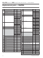
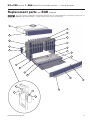
Replacement parts — EG/PEG. . . . . . . . . . . . . . . . . . . . . . . . . . . . . . . . . . 34
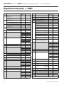
Replacement parts — EGH . . . . . . . . . . . . . . . . . . . . . . . . . . . . . . . . . . . . 36
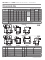
Dimensional data . . . . . . . . . . . . . . . . . . . . . . . . . . . . . . . . . . . . . . . . . . . 38
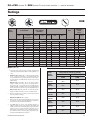
Ratings . . . . . . . . . . . . . . . . . . . . . . . . . . . . . . . . . . . . . . . . . . . . . . . . . . . 39
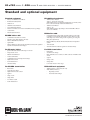
Standard and optional equipment . . . . . . . . . . . . . . . . . . . . . . . . . . . . . 40
Part Number 550-142-782/1112
3
EG & PEG
SERIES
5sEGH
SERIES
5
GAS-FIRED BOILERS
—
BOILER MANUAL
Codes & Checklist
Installation must follow these codes:
s Local codes, laws, provincial and national codes, laws, regulations and ordinances
s .ATIONAL&UEL'AS#ODE!.3):LATESTEDITION
s 3TANDARDFOR#ONTROLSAND3AFETY$EVICESFOR!UTOMATICALLY&IRED"OILERS!.3)!3-%
CSD-1, when required
s .ATIONAL%LECTRIC#ODE
The equipment shall be installed in accordance with those installation regulations in force
in the local area where the installation is to be made. These shall be carefully followed in
all cases. Authorities having jurisdiction shall be consulted before installations are made.
Canadian installations must comply with CAN/CSA B149.1 or B149.2 Installation Codes.
Commonwealth of Massachusetts
When the boiler is installed within the Commonwealth of Massachusetts:
s 4HISPRODUCTMUSTBEINSTALLEDBYALICENSEDPLUMBER
s )FANTIFREEZEISUSEDAREDUCEDPRESSUREBACKmOWPREVENTERDEVICESHALLBEUSED
Certification
Safe operating and other performance criteria were met with the gas manifold and control assembly provided on boiler when boiler underwent tests
SPECIlEDIN!.3):LATESTEDITION
Before locating the boiler:
❏ Check for nearby connection to:
s6ENTINGCONNECTIONS
s'ASSUPPLYPIPING
s%LECTRICALPOWER
❏ Check area around boiler. Remove any combustible materials, gasoline and other flammable liquids.
Failure to keep boiler area clear and free of combustible materials, gasoline
and other flammable liquids and vapors can result in severe personal injury,
death or substantial property damage.
❏ Boiler must be installed so that gas control system components are protected from dripping or spraying water or rain during operation or service.
❏ If new boiler will replace existing boiler, check for and correct system problems, such as:
s3YSTEMLEAKSCAUSINGOXYGENCORROSIONORSECTIONCRACKSFROMHARDWATERDEPOSITS
4
Part Number 550-142-782/1112
EG & PEG
SERIES
5sEGH
SERIES
5
GAS-FIRED BOILERS
—
BOILER MANUAL
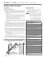
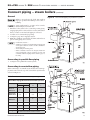
Prepare boiler location
Recommended Service clearances
4ABLE
1. Provide minimum clearances for cleaning and servicing
the boiler and for access to controls and components as
listed in the table at right.
2. Provide at least screwdriver clearance to jacket front panel
screws for removal of front panel for inspection and minor
service. If unable to provide at least screwdriver clearance,
install unions and shutoff valves in system so boiler can be
moved for servicing.
EG, PEG & EGH -Service and combustible
materials clearances
EG, PEG & EGH - Clearance for service
Minimum
Clearance to boiler jacket
Combustible material clearances
General
1. See Table 1 for clearances to boiler and system components.
2. Clearances to Type B vent materials are as specified by the
vent manufacturer.
Top 46”
Front 18”
Back
6”
Left side 24”
Right side
6”
Clearance to combustible materials
Minimum
EG & PEG
Minimum
EGH
Clearance to boiler jacket
Alcove (not closet) installations only
Top
%'AND0%'BOILERSARENOTAPPROVEDFOR
CLOSETINSTALLATION
EG and PEG boilers are approved for ALCOVE
installation, with minimum clearances to
combustible surfaces as shown in Table 1. See
Figure 1. The front side must be completely open
— that is, a three-walled room.
46”
46”
Front 3”
18”
Back
6”
24”
Left side 4”
24”
Right side
4”
24”
1/2”
1/2”
6”
6”
manufacturer
manufacturer
6”
6”
Clearance to piping and vent components
Water and steam pipes
%'(BOILERSARENOTAPPROVEDFORALCOVEOR
CLOSETINSTALLATION
Vent pipe Type B vent piping
&IGUREAlcove installation (EG & PEG only)
Vent damper
EGH installations
1.
2.
3.
See Table 1 for clearances to boiler and system components.
Provide the clearances for service and clearance to combustible materials as listed on this page.
Install in a space that is large in comparison to the size of
the boiler (see National Fuel Gas Code for details).
Residential garage installations
Take the following special precautions when installing the boiler in
a residential garage. If the boiler is located in a residential garage,
PER!.3):
s -OUNTTHEBOILERAMINIMUMOFINCHESABOVETHEmOOROF
the garage to assure the burner and ignition devices will be
no less than 18 inches above the floor.
s ,OCATE OR PROTECT THE BOILER SO IT CANNOT BE DAMAGED BY A
moving vehicle.
Part Number 550-142-782/1112
5
EG & PEG
SERIES
5sEGH
SERIES
5
GAS-FIRED BOILERS
—
BOILER MANUAL
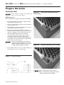
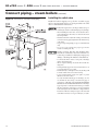
1 Prepare boiler location (continued)
Flooring and foundation
Vent System
Do not install boiler on combustible
flooring or carpeting even if a concrete or
aerated foundation is used. Fire can result,
causing severe personal injury, death or
substantial property damage.
1. See Figure 2. A level concrete or solid brick pad is
required if:
Failure to follow all instructions can result in flue gas spillage and carbon monoxide emissions, causing severe personal
injury or death.
a) There is a possibility of the floor becoming flooded.
b) Non-level conditions exist.
Do not alter boiler draft diverter or place any obstruction or
non-certified vent damper in breeching or vent system. CSA
certification will become void. Flue gas spillage and carbon
monoxide emissions will occur causing severe personal injury
or death.
2. An aerated boiler foundation is recommended if
any of the following conditions exist:
a) Electrical wiring or telephone cables buried in the
concrete floor of the boiler room.
b) Concrete floor is “green.”
c) There is a history of the floor becoming flooded.
d) Water is channeled under the concrete.
&IGURE
Boiler foundation
4ABLEMinimum foundation size
Boiler Foundation Size - Inches
Boiler No.
6
“L”
Boiler No.
“L”
EG 30-35
19
EGH 85
40 1/4
EG 40-45
23 1/4
EGH 95
44 1/2
EG 50-55
27 1/2
EGH 105
48 3/4
EG 65
31 3/4
EGH 115
53
EG 75
36
EG 125
57 1/4
Inspect existing chimney before installing boiler. Failure to
clean or replace perforated pipe or tile lining will cause severe
personal injury or death.
The following requirements apply when you remove an existing boiler from a vent system shared with other appliances. If
the new boiler will not use the common vent, you must test
(as described below) each remaining appliance — operating
by itself — to verify that the vent system operates adequately.
When removing boiler from existing common vent system:
At the time of removal of an existing boiler, the following steps shall be
followed with each appliance remaining connected to the common venting
system placed in operation, while the other appliances remaining connected
to the common venting system are not in operation.
a. Seal any unused openings in the common venting system.
B 6ISUALLYINSPECTTHEVENTINGSYSTEMFORPROPERSIZEANDHORIZONTALPITCH
and determine there is no blockage or restriction, leakage, corrosion or
other deficiencies which could cause an unsafe condition.
c. Test vent system — Insofar as is practical, close all building doors and
windows and all doors between the space in which the appliances remaining connected to the common venting system are located and other
spaces of the building. Turn on clothes dryers and any appliance not
connected to the common venting system. Turn on any exhaust fans,
such as range hoods and bathroom exhausts, so they will operate at
maximum speed. Do not operate a summer exhaust fan. Close fireplace
dampers.
d. Place in operation the appliance being inspected. Follow the operating
instructions. Adjust thermostat so appliance will operate continuously.
e. Test for spillage at draft diverter relief opening after 5 minutes of main
burner operation. Use the flame of a match or candle.
f. After it has been determined that each appliance remaining connected
to the common venting system properly vents when tested as outlined
above, return doors, windows, exhaust fans, fireplace dampers, and any
other gas-burning appliance to their previous conditions of use.
Any improper operation of the common venting system should be corrected
SOTHEINSTALLATIONCONFORMSWITHTHE.ATIONAL&UEL'AS#ODE!.3):
NFPA 54 and/or CAN/CGA B149 or B149.2, Installation Codes. When resizing any portion of the common venting system, the common venting system
should be resized to approach the minimum size as determined using the
APPROPRIATETABLESINTHE.ATIONAL&UEL'AS#ODE!.3):.&0!
and/or CAN/CGA B149 or B149.2, Installation Codes.
Part Number 550-142-782/1112
EG & PEG
SERIES
5sEGH
SERIES
5
GAS-FIRED BOILERS
—
BOILER MANUAL
Prepare boiler location
Vent System (continued)
Air contamination
Chimney or vent requirements
6ENTING MUST BE INSTALLED ACCORDING TO THE .ATIONAL &UEL 'AS #ODE
!.3):nLATESTEDITIONANDAPPLICABLEBUILDINGCODES#ANADIAN
installations must comply with B149.1 or B149.2 Installation Codes.
2. See “Ratings” on page 38 for minimum chimney or vent sizes. Chimney
or vent termination:
1. Please review the following information on potential
combustion air contamination problems.
2. See Table 3 for products and areas which may cause
contaminated combustion air.
To prevent potential of severe personal
injury or death, check for products or
areas listed below before installing boiler.
If any of these contaminants are found:
s2EMOVECONTAMINANTSPERMANENTLY
— OR —
s)SOLATEBOILERANDPROVIDEOUTSIDECOMbustion air. See national, provincial or
local codes for further information.
s
A chimney, or any vent other than a Type B vent with listed vent cap,
must extend at least 3 feet above the highest point where it passes
through a roof of a building, and at least 2 feet higher than any portion
of a building within a horizontal distance of 10 feet.
s
4YPE"VENTSWITHLISTEDCAPSMAYTERMINATEASIN&IGUREIFNOCLOSER
than 8 feet from a vertical wall or similar obstruction.
s
/THERWISE4YPE"VENTSMUSTTERMINATEATLEASTFEETABOVETHEROOF
penetration and at least 2 feet higher than any portion of a building
within 10 feet.
3. A lined chimney is preferred and must be used when required by local,
state, provincial and national codes, laws, regulations and ordinances.
6ITREOUSTILELININGSWITHJOINTSTHATPREVENTRETENTIONOFMOISTUREAND
linings made of noncorrosive materials are best. Advice for flue connections and chimney linings can be obtained from local gas utility. Type B
double-wall metal vent pipe or single-wall vent pipe may be used as a
liner.
4. Cold masonry chimneys, also known as outside chimneys, typically have
one or more walls exposed to outside air. When any atmospheric gasfired boiler with automatic vent damper is vented through this type of
chimney, the potential exists for condensation to occur. Condensation
can damage a masonry chimney. The following are recommended to
prevent possible damage.
a. Line chimney with corrosion-resistant metal liner such as AL29-4C®
single-wall stainless steel or B-vent. Size liner per National Fuel Gas Code
!.3):nLATESTEDITION
b. Provide drain trap to remove any condensate.
5. Where two or more gas appliances vent into a common chimney or vent,
equivalent area should be at least equal to area of vent outlet on largest
appliance plus 50 percent of vent outlet area of additional appliances.
&IGURE
Terminations with Type B vent fitted with listed cap, provided
vent is at least 8 feet from any vertical wall or similar
obstruction
4ABLE
Contaminants to avoid
Products to avoid
!
"
!#
!
Refrigerant leaks
Paint or varnish removers
$
Cements and glues
%
!#
&&
Adhesives used to fasten building products and other
similar products
Areas likely to have contaminants
'
Metal fabrication plants
Refrigeration repair shops
Photo processing plants
%
Plastic manufacturing plants
()
*
Remodeling areas
+
,
Part Number 550-142-782/1112
7
EG & PEG
SERIES
5sEGH
SERIES
5
GAS-FIRED BOILERS
—
BOILER MANUAL
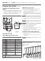
Prepare the location
!IROPENINGS
Provide adequate combustion and ventilation air
to assure proper combustion and reduce the risk
of severe personal injury, death or substantial property damage caused by flue gas spillage and carbon
monoxide emissions.
Combustion air and ventilation openings must comply with
THE.ATIONAL&UEL'AS#ODE!.3):nLATESTEDITIONORAPplicable local building codes. Canadian installations must comply
with B149.1 or B149.2 Installation Codes.
Air opening sizes in the following are given in free area (after
correction for louver obstruction).
Option 1 — Provide (2) openings:
Tight construction — Definition:
4IGHTCONSTRUCTIONMEANSPER!.3):
s 7ALLSANDCEILINGSEXPOSEDTOTHEOUTSIDEATMOSPHEREHAVEA
continuous water vapor retarder with a rating of 1 perm or
less with openings gasketed. AND
s Weather-stripping has been added on openable windows
and doors. AND
s #AULKINGORSEALANTSAREAPPLIEDTOAREASSUCHASJOINTSAROUND
windows and door frames, between sole plates and floors, between wall-ceiling joints, between wall panels, at penetrations
for plumbing, electrical, and gas lines, and in other openings.
Tight construction requirements
If building is of tight construction and air is taken from inside
the building, provide two openings in building outside wall, one
within 12 inches of ceiling, the other within 12 inches of the floor.
Each opening must have a minimum free area of 1 square inch
per 1,000 Btuh of all appliances in the building.
Exception
NO combustion air openings are needed when the boiler (and
other appliances) are installed in a space with a volume NO LESS
than 50 cubic feet per 1,000 Btuh of all installed appliances. Sum
the total input of all appliances in MBH (1,000’s of Btuh) and
multiply this number times 50. Building must not be of Tight
construction (see above).
Example: For total input of 100 MBH (100,000 Btuh), minimum
volume is 50 x 100 = 5,000 cubic feet. At a ceiling height of 8 feet,
space must have at least 5,000 ÷ 8 = 625 square feet (25 feet x 25
feet, for instance).
Exhaust fans and air movers
The appliance space must never be under a negative pressure.
Always provide air openings sized not only to the dimensions
required for the firing rate of all appliances, but also to handle
the air movement rate of the exhaust fans or air movers using air
from the building or space.
Motorized air dampers
If the air openings are fitted with motorized dampers, electrically
Option 2 — Provide (1) opening:
interlock the damper to:
A single combustion air opening can be used, provided:
s 0REVENTTHEBOILERFROMlRINGIFTHEDAMPERISNOTFULLYOPEN
s 4HEopening must commence within 12 inches of the ceiling.
s 3HUTTHEBOILERDOWNSHOULDTHEDAMPERCLOSEDURINGBOILER
s 4HEBOILERMUSTHAVECLEARANCESOFATLEASTINCHFROMBOTH
operation.
sides and back, and 6 inches from the front.
To accomplish this interlock, wire an isolated contact (proving the
s 4HEOPENINGMUSTCONNECTDIRECTLYTOTHEOUTDOORSORTOA damper open) in series with the thermostat input to the boiler.
space that communicates directly to the outdoors.
The boiler will not start if this damper is closed, and will shut
s 4HEAIRCANBEPROVIDEDTHROUGHADIRECTOPENINGORTHROUGH down should damper close during operation.
a horizontal or vertical duct.
s 4HEFREEAREAOFTHEOPENINGMUSTBEATLEASTEQUALTOTHESUM 0LACEMENTANDSETUP
of all vent connectors in the space.
Place boiler/crate near position
s 4HEFREEAREAOFTHEOPENINGMUSTBEATLEASTSQUAREINCH 1. Leave boiler in crate and on pallet until installation site is
per 3000 Btu/hr input rating of all equipment located in the
ready.
space.
2. Move entire crate and pallet next to selected location.
3. Remove crate. Leave boiler on pallet.
4. Unbolt boiler from pallet.
5. Remove boiler from pallet.
8
Part Number 550-142-782/1112
EG & PEG
SERIES
5sEGH
SERIES
5
GAS-FIRED BOILERS
—
BOILER MANUAL
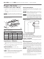
Prepare the boiler
Placing the boiler
Block assembly is extremely heavy. Handle with
caution to avoid personal injury.
Figure 4a
Corner after exposed silicone has
been removed.
EGH boilers only —
When an EGH block assembly is taken apart for handling:
1. Put a support under center of block. Support must be
within ½ inch of block bottom.
2. Detach seal replacement kit from the draw rod. Remove
short center draw rods.
3. Tip half blocks on end as shown in Figure 4. Save elastomer sealing ring between sections.
4. Remove the exposed silicone from the socket areas
located in the bottom-front and top-rear corners of the
casting. See Figure 4a. Do not remove the rope seal.
5. After moving half-blocks into desired location,
clean port surfaces with clean, dry rag. Do not use
petroleum-based solvents. Place sealing rings in
recessed ports. Place new silicone in the socket area as
seen in Figure 4b. It is critical to place enough silicone
in this area to reseal the castings.
Do not use petroleum-based cleaning or
sealing compounds in boiler system. Severe
damage to system components can result,
causing substantial property damage.
Figure 4b
Placing of new silicone in the sockets.
6. Re-assemble block in reverse order. When drawing sections together, use 45 ( ± 5 ) ft-lbs torque.
&IGURE
Handling split blocks
Place enough silicone in the socket to
make a seal with the mating surface on the
adjacent casting when assembled.
Part Number 550-142-782/1112
9
EG & PEG
SERIES
5sEGH
SERIES
5
GAS-FIRED BOILERS
—
BOILER MANUAL
Prepare the boiler (continued)
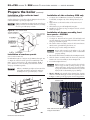
Installation of optional indirect water
heater
1. For a boiler ordered with internal type indirect water heater,
REMOVE HEATER OPENING COVER PLATE WATER BOILERS n ROUND
PLATEONLEFTSIDESTEAMBOILERSnRECTANGULARPLATEONFRONT
2. Install heater(s) as shown on page 18. Do not over tighten
studs and nuts - damage to the gasket can occur.
&IGURE
Hydrostatic pressure test
Pressure test before attaching gas piping or electrical supply.
1. Plug any necessary boiler tappings or openings.
2. Do not use gauge supplied with boiler for pressure testing.
Install gauge with appropriate range.
3. &ILLBOILERWITHWATER6ENTALLAIR4ESTSTEAMBOILERSBETWEEN
45 - 55 psi. Test water boilers at 1-1/2 times maximum working pressure.
Do not leave boiler unattended. A cold water fill could
expand and cause excessive pressure, resulting in severe
personal injury, death or substantial property damage.
Boiler tappings (see Table 4)
6ERIFYGAUGEPRESSUREISMAINTAINED#HECKFORLEAKS2EPAIR
if found.
Leaks must be repaired at once. Failure to do so can
cause boiler damage, resulting in substantial property
damage.
Do not use petroleum-based sealing compounds in
boiler system. Severe damage to boiler will result,
causing substantial property damage.
5. Drain boiler and repair leaks if found.
6. Retest boiler after repairing leaks.
7. Remove plugs from any tappings that will be used for controls
and accessories. Refer to Table 4 and Figure 5.
8. On initial start-up check for leaks in the system piping. If
found, repair at once.
Installation of flue baffles (EGH only)
1. Bend the two (2) tabs on the flue baffle approx. 90 degrees in
opposite directions.
2. Slide flue baffles (notch down and to the back) in between
each section.
4ABLE
The installer must install all flue baffles for proper
boiler operation.
Control tapping (see Figure 5)
EG, PEG & EGH
EG & PEG only
Tapping
Size
C
¾”
#
D
¾”
Drain
Drain
E
¾”
G
¾”
Plugged
Piping to compression tank or
auto air vent
H
½”
+
cutoff
Combination pressure
temperature gauge
J
=>
Tri cock tappings
(
:;!<
L
½”
&
&
:;!<
Combination pressure
temperature gauge
1
(
#&
?
#
?
#
P
(EGH Only)
S
1 ½”
¾”
Steam Boilers
Skim tapping
––
Water Boilers
#:;!<
&IGUREA EGH - Flue baffles
keep from falling through
B
––
:
:
@
Notes:
10
@B%
F&
,
)B
IB:
J+$B
KB;
&
additional operating control.
Part Number 550-142-782/1112
EG & PEG
SERIES
5sEGH
SERIES
5
GAS-FIRED BOILERS
—
BOILER MANUAL
Prepare the boiler (continued)
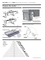
Installation of flue collector hood
(Factory installed on PEG boilers)
Set flue collector hood on boiler as shown in Figure 6b. Use boiler
cement furnished to provide gas-tight seal.
Failure to maintain gas-tight seal can cause flue gas
spillage and carbon monoxide emissions, resulting
in severe personal injury or death.
&IGUREB Flue collector hood
Installation of side refractory -EGH only
1. See Figure 7b & 7d. Hardware for drawer assembly must
be installed (See Figure 10), before sliding refractory in to
place.
2. Apply silicone to the inside surface of the cast iron end
section leg.
3. Slide refractory (2 pieces left & right side) into place.
4. Install four (4) refractory clips (See Figure 7b & 7d) to hold
refractory in place.
Installation of drawer assembly, front
base panels – EG/EGH
(Factory installed on PEG boilers)
1. See Figure 7c. Fasten front base panel (6 ¹⁄₈ inch high) and
rear base channel to section assembly. Seal with boiler cement
along top of insulation panels.
2. The burner drawer assembly consists of the burner drawer,
main burners, gas manifold, pilot burner, etc.
3. Check for proper orifice sizing from Table 5.
Installation of rear base panels
(Factory installed on PEG boilers)
For EG-30 through 75, see Figure 7a, for EGH-85 through -125,
see Figure 7b. Fasten rear base panel (7 5/16 inch high - EG/
PEG - 2 pieces) and rear base (11 17/32 inch high - EGH - 1
piece) channel to section assembly. Seal with boiler cement
along top of insulation panels.
Failure to maintain gas-tight seal can cause flue
gas spillage and carbon monoxide emissions,
resulting in severe personal injury or death.
&IGUREA EG/PEG - Rear base panel and base channel
Proper orifices must be used. Failure to do so will
cause severe personal injury, death or substantial
property damage.
4. Place burners in the drawer assembly as shown in Figures 8 and 9.
5. Slide the drawer assembly under the front base panel and
attach to the section assembly as shown in Figure 10.
6. Level and straighten burners.
Burners must be properly seated in slots in back
burner support with openings facing up. Gas
orifices must inject down center of burner. Failure
to properly seat burners will result in severe personal
injury, death or substantial property damage.
7. %' n %' only: Install rollout thermal fuse element
with wire terminals facing up on front access panel as shown
in Figure 11. Wire per the appropriate Control Supplement.
&IGUREB EGH - Rear base panel & refractory and
refractory clip
Note! Silicone to be applied to inside
of leg of cast surface.
Part Number 550-142-782/1112
11
EG & PEG
SERIES
5sEGH
SERIES
5
GAS-FIRED BOILERS
—
BOILER MANUAL
Prepare the boiler (continued)
&IGURED EGH - Refractory placement & front base panel
&IGUREC %'%'( Front base panel
(Factory installed on PEG boilers)
(Q
B
Note! Silicone to be applied to
inside of leg of cast surface.
@Q>$
and rear base panels needs to be in
I
L
B
&IGURE Burner drawer installation
&IGURE
EGH Burner drawer assembly
See Figure 9 for locations
Flange
to front
of boiler.
'
L
J+$
&IGURE
12
Manifold
Combination
Gas Valve
J+$&
See page 35
for EG
Burner and pilot burner locations
Part Number 550-142-782/1112
EG & PEG
SERIES
5sEGH
SERIES
5
GAS-FIRED BOILERS
—
BOILER MANUAL
Prepare the boiler (continued)
Installation of base shield - EGH only
Draft hood installation
1. See Figure 8, slide base shield under burner drawer assembly.
Attach draft hood to flue collector hood using #10 x 1/2” sheet
metal screws provided. Use boiler cement furnished to provide
gas tight seal.
2. The flanged end of the shield should be located at the front
of the boiler.
The installer must install base shield, flanged end of
shield at front of boiler for proper boiler operation.
&IGURE EG/EGH - Access panel
&ACTORYINSTALLEDon PEG boilers)
Failure to maintain gas-tight seal can cause flue gas
spillage and carbon monoxide emissions, resulting
in severe personal injury or death.
Do not alter boiler draft hood or place any obstruction or non-approved damper in the breeching or
vent system. CSA certification will become void.
Flue gas spillage and carbon monoxide emissions
will occur causing severe personal injury or death.
&IGURE Draft hood
Seal across back of
block assembly with
boiler cement between
cast iron and sheet
metal edge of draft hood
4ABLE
Orifice drill sizes
EG/PEG
EGH
Heating
Value
UBB
Standard
<)
drill size
Standard
<)
drill size
Natural
@&WWW
2.45 mm
2.30 mm
switch to draft hood as shown on page 34, Drawing Ref. Letter “K”.
Connect wires as shown in the appropriate Control Supplement.
Propane
I&XWW
1.55 mm
1.40 mm
Damper installation
Type of Gas
Spill switch installation
%'n%' and 0%'n0%' boilers only, fasten spill
If damper will be installed, see Control Supplement for information.
Inspect burners – PEG boilers
1. PEG boiler are factory-assembled, but the burners and base
panels should be inspected to ensure they are in good condition.
2. Remove the access panel (Figure 11) and inspect the burners
per step 6 above. Replace the access panel.
Jacket installation
(Factory installed on PEG)
1. Remove the proper knockout discs from panels as shown in
Table 4, page 10.
Tankless and storage heater knockouts must be
removed for EG and EGH boilers with optional
tankless heaters prior to jacket installation.
2. Follow Jacket Instructions in jacket carton.
Part Number 550-142-782/1112
Breeching erection
Connect from draft hood or damper outlet to chimney or vent
with same size breeching. Where possible, vertical venting to the
outside from draft hood or damper outlet will offer best performance. Where horizontal breeching is used, slope upward at least
1/4 inch per lineal foot toward chimney or vent and support with
hangers to prevent sagging.
A vertical height of 3 feet to 5 feet of breeching before
any elbow or horizontal breeching is recommended
to reduce chances of flue gas spillage at draft hood
on EGH-95 thru -125 boilers (not restricted on any
EG or EGH-85). Long horizontal breechings, excessive numbers of elbows or tees, or other obstructions
which restrict the flow of combustion gases should
be avoided.
Breeching must not be connected to any portion of a mechanical
draft system operating under positive pressure.
13
EG & PEG
SERIES
5sEGH
SERIES
5
GAS-FIRED BOILERS
—
BOILER MANUAL
Connect piping – water boilers – EG only
General
Install the boiler jacket before connecting return piping. (Supply piping can
be connected before or after jacket installation.) Connect controls after all
piping is connected.
If installation is to comply with ASME or Canadian requirements, an additional high temperature limit is needed. Install control in supply piping
between boiler and isolation valve. Set second control to minimum 20 °F
above setpoint of first control. Maximum allowable setpoint is 240 °F. See
page 23 for wiring.
A low water cutoff device is required when boiler is installed above radiation level or by certain state or local codes or insurance companies. Use
low water cutoff designed for water installations. Electrode probe-type
is recommended. Purchase and install in tee supply piping above boiler.
Use backflow check valve in cold water supply if required by local codes.
Isolation valves
Isolation valves are required to enable servicing of the boiler’s temperature
sensor. Install as shown in appropriate piping diagram.
Near-boiler piping
Boiler connections
1. EG — Connect supply and return to left end.
2. Plug all unused connections.
Systems operating at or above 130°F
1. See Table 6 and Figure 14 (diaphragm-type or bladder-type expansion
tank) or Figure 13 (closed-type expansion tank) on page 12 for nearboiler piping for systems designed for return water at least 130 °F.
Low-temperature systems
1. See page 16 (Figures 16 and 17) for near-boiler piping for low-temperature or high-volume systems.
2. See page 15 (Figure 15) for boilers used with refrigeration systems.
4ABLE
Minimum recommended pipe sizes
Minimum Recommended Pipe Sizes (for 20° F rise)
Boiler
number
Supply
“A”
Return
“B”
Supply
“A”
Return
“B”
1”
1”
1 ½”
1 ½”
EG-40, 45, 50
1 ¼”
1 ¼”
2”
2”
EG-55, 65
1 ½”
1 ½”
2 ½”
2 ½”
2”
2”
2 ½”
2 ½”
EG-30, 35
EG-75
Note:
Y%
Z
I[(
temperature rise through the boiler.
Circulator
The circulator is shipped loose (wiring pre-attached to
boiler) to allow you to locate it either in the return or
supply piping, as desired. See page 12 for a typical installation. Pipe the expansion tank to the suction side of the
circulator whenever possible. Install an air separator in
the supply piping. Connect the expansion tank to the air
separator only if the separator is on the suction side of
the circulator. Always install the system fill connection
at the same point as the expansion tank connection to
the system. Figures 13 and 14 show typical near-boiler
piping connections.
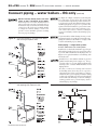
Expansion tank
Diaphragm-type or bladder-type tank — Figure 14
Relief valve
Install relief valve vertically in ¾” tapping on side of boiler. See the tag attached to the relief valve for manufacturer’s instructions.
To avoid water damage or scalding due to valve operation,
discharge line must be connected to relief valve outlet and
run to a safe place of disposal. Terminate the discharge line
to eliminate possibility of severe burns should the valve discharge.
1. Ensure expansion tank size will handle boiler and
system water volume and temperature. Tank must
be located in boiler return piping as close to boiler
as possible, before inlet side of circulator. See tank
manufacturer’s instructions for details.
2. Install an automatic air vent as shown.
s $ISCHARGELINEMUSTBEASSHORTASPOSSIBLEANDBETHESAMESIZEAS
the valve discharge connection throughout its entire length.
s $ISCHARGELINEMUSTPITCHDOWNWARDFROMTHEVALVEANDTERMINATE
at least 6” above the floor drain where any discharge will be clearly
visible.
s 4HEDISCHARGELINESHALLTERMINATEPLAINNOTTHREADEDWITHAMATERIAL
serviceable for temperatures of 375 °F or greater.
s $ONOTPIPETHEDISCHARGETOANYPLACEWHEREFREEZINGCOULDOCCUR
s .OSHUTOFFVALVESHALLBEINSTALLEDBETWEENTHERELIEFVALVEANDBOILER
or in the discharge line. Do not plug or place any obstruction in the
discharge line.
s &AILURETOCOMPLYWITHTHEABOVEGUIDELINESCOULDRESULTINFAILUREOF
the relief valve to operate, resulting in possibility of severe personal
injury, death or substantial property damage.
s 4ESTTHEOPERATIONOFTHEVALVEAFTERlLLINGANDPRESSURIZINGSYSTEM
by lifting the lever. Make sure the valve discharges freely. If the valve
fails to operate correctly, replace it with a new relief valve.
1. Ensure expansion tank size will handle boiler and
system water volume and temperature. See tank
manufacturer’s instructions for details.
2. Connect tank to ½” NPT tapping located behind
supply outlet, using ½” NPT piping. Pitch any
horizontal piping up towards tank 1 inch per 5 feet
of piping.
14
Closed-type tank — Figure 13
Undersized expansion tanks cause system
water to be lost from relief valve and
makeup water to be added through fill
valve. Eventual section failure can result.
Water piping — multiple zone systems
Install system piping using either circulator zoning or
zone valve zoning. Install expansion tank on suction side
of system circulator. Always connect fill line only at the
expansion tank — never at another point in the system.
Part Number 550-142-782/1112
EG & PEG
SERIES
5sEGH
SERIES
5
GAS-FIRED BOILERS
—
BOILER MANUAL
Connect piping – water boilers – EG only (continued)
$/./4CONNECTDIRECTLYFROMWIREZONE
VALVES TO THE44 TERMINALS ON THE BOILER.
When using 3-wire zone valves, install an isolation
relay. Connect the zone valve end switch wires to
the isolation relay coil. Connect the isolation relay
contact across the boiler T-T terminals. Failure
to comply can result in damage to boiler components or cause unreliable operation, resulting
in severe property damage.
&IGURE Recommended piping – forced hot water boilers
with closed type expansion tanks
Use Figure 13 or Figure 14 only for systems designed
for return water at least 130 °F. For systems with
low return water temperature possible, such as converted gravity systems and radiant heating systems,
install bypass piping (see page 16) to protect boiler
against condensation. Failure to prevent low return
water temperature to the boiler could cause corrosion of the boiler sections or burners, resulting in
severe personal injury, death or substantial property
damage.
If system includes radiant heating circuits, provide
piping and controls to regulate the temperature supplying the radiant circuits. Failure to comply could
result in substantial property damage.
Water piping — refrigeration systems
Prevent chilled water from entering boiler
Install boiler so that chilled medium is piped in parallel with the heating boiler. Use appropriate valves
to prevent chilled medium from entering boiler. See
Figure 15 for typical installation of balancing valve
and check valve.
Install boiler so that chilled medium is piped in
parallel with heating boiler (Figure 15). Use appropriate valves to prevent chilled medium from
entering boiler. Consult AHRI Installation and
Piping Guides.
&IGURE Recommended piping – forced hot water boilers
with diaphragm type expansion tanks
Part Number 550-142-782/1112
If boiler is connected to heating coils located in
air handling units where they can be exposed to
refrigerated air, use flow control valves or other automatic means to prevent gravity circulation during
cooling cycle. Circulation of cold water through the
boiler could result in damage to the heat exchanger,
causing possible severe personal injury, death or
substantial property damage.
&IGURE Recommended piping – refrigeration systems
15
EG & PEG
SERIES
5sEGH
SERIES
5
GAS-FIRED BOILERS
—
BOILER MANUAL
Connect piping – water boilers – EG only
&IGURE System bypass piping in boiler loop with separate
system circulator, using primary/secondary
piping.
(continued)
&IGURE Boiler bypass piping — use only for high water
content systems —DO NOT use for radiant panel
systems.
System bypass method
1. Apply bypass piping of Figure 16 to high water content
systems, radiant panel systems or any system that is likely
to operate with low return water temperature for extended
periods.
2. The bypass arrangement shown protects the boiler from damage caused by condensate corrosion due to low return water
temperature and protects low temperature systems from too
high a supply temperature.
3. Adjust the bypass valves as indicated below.
Boiler bypass method
1. Apply bypass piping of Figure 17 to high water content
systems, such as converted gravity systems.
2. The bypass arrangement shown protects the boiler from
damage caused by condensate corrosion due to low return
water temperature. This method does not provide protection
from high temperature water being supplied to the system.
3. DO NOT apply this piping to radiant panel systems.
4. Adjust the bypass valves as indicated below.
Adjust Bypass valves 1 and 2 as follows:
1. Start with valve 2 fully closed, valve 1 fully open.
2. Slowly open valve 2 while closing valve 1. Adjust the valves
until the boiler pressure/temperature gauge reads 160 °F or
higher. As you open the valves, pause long enough to allow
temperatures to level off. It takes a while for the boiler water
temperature to rise as the flow changes.
3. Bypass valve 2 allows hot boiler outlet water to blend with
colder return water, raising the supply temperature to the
boiler. Bypass valve 1 balances the pressure drop through
valve 2.
4. The purpose of this piping is to raise the return water temperature
to the boiler enough to prevent condensation of flue gases.
Adjust Bypass valves 1 and 2 as follows:
1. Start with valve 1 fully closed, valve 2 fully open.
2. Slowly open valve 1 while closing valve 2. Adjust the valves
until the boiler pressure/temperature gauge reads approximately 60 °F higher than the system temperature gauge. As
you open the valves, pause long enough to allow temperatures
to level off. It takes a while for the boiler water temperature
to rise as the flow changes.
3. Bypass valve 1 controls system flow rate. Bypass valve 2
controls flow through the boiler.
4. The purpose of this piping is to cause a high enough temperature rise in the boiler that the average temperature will
be warm enough to prevent condensation of flue gases.
Install all components specified above and adjust valves as described to prevent low temperature in the boiler. Failure to
prevent low water temperature in the boiler could cause corrosion of the boiler sections or burners, resulting in severe
personal injury, death or substantial property damage.
16
Part Number 550-142-782/1112
EG & PEG
SERIES
5sEGH
SERIES
5
GAS-FIRED BOILERS
—
BOILER MANUAL
Connect piping – steam boilers (continued)
General
&IGURE Recommended piping for parallel-flow systems
Failure to properly pipe the boiler may result in
improper operation and damage to the boiler or
building.
1.
2.
3.
4.
Steam supply must be on same end as controls.
Return may be from either end.
Install the boiler jacket before connecting return piping.
(Supply piping can be connected before or after jacket installation.) Connect controls after all piping is connected.
See Table 7 for recommended pipe sizing.
See Figure 5, page 10, for tapping locations.
EGH only - install 3/4” system blow-off (drain) valve in lowest
part of return piping close to boiler.
Condensate return —
s 3ATISFACTORYOPERATIONOFASTEAMHEATINGSYSTEMDEPENDS
on adequate condensate return to boiler to maintain a
steady water level.
s !VOIDADDINGRAWMAKEUPWATER
s 7HERE CONDENSATE RETURN IS NOT ADEQUATE INSTALL LOW
water cutoff/pump control, condensate receiver and
condensate boiler feed pump. Refer to Table 5, page 16,
for sizing.
Connecting to parallel-flow piping
1. See Figure 18 for parallel-flow steam systems.
Connecting to counterflow piping
When connecting to a counterflow system, the boiler steam supply must connect into the top of the counterflow system header,
as shown in Figure 19.
4ABLE
Recommended steam boiler pipe sizing
Steam Boiler Piping Minimum Recommended Pipe Sizes
Boiler Model
Riser Pipe Size
Header
H
*
Equalizer
J
A
B
2”
––
2”
1 ½”
EG-40, 45, 50
PEG-40, 45, 50
2 ½”
––
2 ½”
1 ½”
EG-55, 65, 75
PEG-55, 65
3”
––
3”
1 ½”
EGH-85, 95
2”
2”
3”
1 ½”
EGH-105
2 ½”
2 ½”
3”
1 ½”
EGH-115, 125
2 ½”
2 ½”
4”
1 ½”
EG-30, 35
PEG-30, 35
*
IQ>
B
Part Number 550-142-782/1112
17
EG & PEG
SERIES
5sEGH
SERIES
5
GAS-FIRED BOILERS
—
BOILER MANUAL
Connect piping – steam boilers (continued)
&IGURE Connection to counterflow steam piping
Installing the relief valve
Install relief valve in tapping on top of boiler. See Table 4, page
10, for control tapping locations. See the tag attached to the relief
valve for manufacturer’s instructions.
Follow the steps below to avoid potential severe personal injury, death or substantial property damage.
s 7HENINSTALLINGTHERELIEFVALVEENSURETHATALLCONNECtions, including the valve inlet, are clean and free from
any foreign matter.
s -OUNTTHERELIEFVALVEONLYINTHEVERTICALPOSITIONDIRECTLY
connected to the tapping designated in the manual on top
of the boiler.
s 5SEPIPECOMPOUNDSPARINGLYORTAPEONEXTERNALTHREADS
only.
s $O NOT USE A PIPE WRENCH 5SE PROPER TYPE AND SIZE
wrench on wrench pads only.
During operation, this valve may discharge large
amounts of steam and/or hot water. Therefore, to
reduce the potential for bodily injury and property
damage, a discharge line MUST be installed that:
s )SCONNECTEDFROMTHEOUTLETTOASAFEPOINTOFDISCHARGE
with no intervening valve.
s !LLOWSCOMPLETEDRAINAGEOFBOTHTHEVALVEANDTHEDIScharge line.
s )SINDEPENDENTLYSUPPORTEDANDSECURELYANCHOREDSOAS
to avoid applied stress as possible.
s 4ERMINATESFREELYTOATMOSPHEREWHEREANYDISCHARGEWILL
be clearly visible and is at no risk of freezing.
s )SOVERITSENTIRELENGTHOFAPIPESIZEEQUALTOORGREATER
than that of the valve outlet.
Use only schedule 40 metal pipe for discharge. (Do not
use schedule 80, extra strong or double strong pipe or
connections.) DO NOT CAP, PLUG OR OTHERWISE
/"3425#4$)3#(!2'%0)0%/54,%4)FDISCHARGE
is piped upward, a condensate drain must be provided in
the elbow below the vertical pipe to prevent condensate
from returning into the valve. Failure to comply with these
instructions will cause a dangerous spray of hot water and
steam that would cause severe personal injury or death.
18
Part Number 550-142-782/1112
EG & PEG
SERIES
5sEGH
SERIES
5
GAS-FIRED BOILERS
—
BOILER MANUAL
Connect piping – steam boilers (continued)
Condensate return
&IGURE Recommended piping for parallel-flow systems
with optional reservoir pipe
Modern steam boilers are designed to steam for less time than
older, larger boilers. When replacing an older steam boiler the
system condensate return time may be longer than the steaming
time. This could cause the following problems:
1. Boilers fitted with an automatic water feed could overfill.
2. Units fitted with only a low water cutoff would shut down
and cycle while waiting for condensate to return.
Following is a simple method for determining whether or not a
reservoir pipe is required to lengthen steaming time for a residential installation:
1. Disconnect condensate return line at existing boiler.
2. Heat boiler and allow to steam for 10 minutes. Turn off boiler.
3. Measure length of time from when boiler started to steam to
when condensate begins to return through condensate line.
4. Measure length of time from when condensate begins to
return to when it stops returning. Divide this time by 2.
5. Add time measured in step 3 to time calculated in step 4. This
sum is the average time required for condensate to return to
the boiler.
6. If this total time is 10 minutes or less, no reservoir pipe is
needed.
If total time for condensate to return to boiler (from step 5) is
more than 10 minutes, a reservoir pipe (or boiler feed system) is
recommended. See Table 8 and Figure 20 for suggested reservoir
pipe size. Install as shown in Figure 20.
For larger systems (as noted in Table 8), use a boiler feed system
with a condensate tank and feed pump. You will have to install a
low water cutoff/pump control on the boiler to operate the pump.
Use Table 9 to size boiler feed systems. See Figure 5, page 10, for
tapping locations. (The use of a combination condensate tank and
float-controlled condensate return pump is not recommended.)
For most residential installations a reservoir pipe may be all that
is necessary to ensure proper operation.
4ABLE
Boiler
model
number
Reservoir pipe sizing
Max.
boiler
gross
output
Time from initial steaming to average condensate return
\]W
15 minutes
20 minutes
Boiler
Model
gallons
pipe
length
gallons
pipe
length
gallons
pipe
length
EG/PEG-30,-35
75
¾
¾
1½
1½
3
2½
EG/PEG-40,-45
125
1¼
1¼
2½
2¼
EG/PEG-50
145
1½
1½
3
2½
EG/PEG-55
167
1¾
1¾
EG/PEG-65
209
2¼
2¼
EG-75
247
2½
2½
EGH-85
243
2½
2½
Gross
Output Gallons
Pounds Condensate
Steam
Per
Per
Hour
Hour
Minimum Condensate
Receiver Capacity (Gal.)
Minutes of boiler
operation:
15
30
45
60
Recommended
Maximum
Feed
Pump
Capacity
GPM *
EG/PEG-30
65
7½
2
5
7
10
0.3
EG/PEG-35
86
10
3
7
10
13
0.3
EG/PEG-40
108
12 ½
4
8
12
17
0.4
EG/PEG-45
130
15
5
10
15
20
0.5
EG/PEG-50
151
17 ½
6
12
17
23
0.6
EG/PEG-55
174
20
7
13
20
27
0.7
EG/PEG-65
218
25
8
17
25
33
0.8
EG-75
257
29 ½
10
20
29
39
1.0
U
EGH-85
253
29
10
19
29
39
1.0
EGH-95
290
33 ½
11
22
33
45
1.1
U
EGH-105
325
37 ½
12
25
37
50
1.3
EGH-115
361
41 ½
14
28
41
55
1.4
EGH-125
398
46
15
31
45
61
1.5
Not recommended –– Use boiler feed system if needed
'
@WB
Part Number 550-142-782/1112
Boiler feed system sizing
30 minutes
MBH
EGH-95 up
4ABLE
*
^
"
&
B
19
EG & PEG
SERIES
5sEGH
SERIES
5
GAS-FIRED BOILERS
—
BOILER MANUAL
Install boiler controls
Failure to properly install, pipe and wire
boiler controls may result in severe damage to the boiler, building and personnel.
&IGURE Probe-type low water cut-off
Water boiler - EG only
1. Install controls as shown on Control Tapping Table
and Figure 5, page 10.
2. Low water cut off for water boilers:
a) Must be installed if boiler is located above radiation
level.
b) May be required on water boilers by certain state,
local or territorial codes or insurance companies.
If a low water cut-off is used on a water boiler, use
a control designed especially for water installations.
An electrode probe type may be located in a tee in
the supply line above boiler, also see Table 4, page 10.
3. If system is to be ASME inspected and approved,
an additional high temperature limit is needed.
Purchase and install in supply line above boiler.
&IGURE Float-type low water cut-off
Steam boiler - EG, PEG & EGH
Water line dimension are measured from
bottom of boiler section leg where it rests
on the boiler room floor or boiler foundation.
1. For steam boilers furnished with probe-type low
water cut-offs, install as shown in Figure 21.
2. For steam boilers furnished with float type low water
cut-off, install controls as illustrated in Figure 22.
Install blowdown line in bottom of cutoff. See Figure 22 and control manufacturer’s instructions for
details.
Pipe blowdown line near floor close to
floor drain to eliminate potential of severe
burns. Do not plug, valve or place any
obstruction in blowdown line.
a) Other float-type water-level controls for EGH steam
boilers are shown in Figure 23. (Use 1 inch I.P.S.
connections).
b) Water feeders are not recommended for primary
control. A low-water cut-off with pump controller is
recommended with a condensate receiver and feed
pump.
3. Install remaining controls as shown in Table 4 and
Figure 5, page 10.
20
:;!<
:;!<
:;!<
&IGURE %'(ONLY - Piping for optional float-type
water level controllers for steam boilers
L.W.C.O.
Dim A.
No. 247-2
7 ³/16”
No. 61
I_>
No. 63
I_>
No. 51-2
1 ½”
*B@XW&@X]
2 ¼”
No. 93
I_>
LWCO model numbers are manufacturer’s part
numbers that can be found in the Weil-McLain
Trade Price Schedule.
Part Number 550-142-782/1112
EG & PEG
SERIES
5sEGH
SERIES
5
GAS-FIRED BOILERS
—
BOILER MANUAL
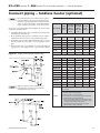
Connect piping – tankless heater (optional)
EG and EGH boilers for tankless heater application are available only on special order as factoryinstalled optional equipment. Standard boilers
cannot be adapted for heater use. Install a tankless
heater only in a steam boiler or forced hot water.
For correct operation, install as shown in Figure 24 (water boilers)
or Figure 25 (steam boilers).
1. Automatic mixing valve must be installed per mixing valve
manufacturer’s instructions.
2. Flow regulating valve must be installed. Size according to
intermittent draw of heater as shown in following table.
3. Operating control with a small differential scale is recommended. Install in temperature control tapping in heater
plate.
4. In hard water areas, it is advisable to soften cold domestic
supply water to the tankless heater to prevent lime buildup.
&IGURE Tankless heater piping EG (water boiler)
4ABLE
Minimum recommended pipe sizes
Heating
Number
*K
Intermittent
Draw GPM
100°F Av.
Temp. Rise
*@
Continuous
Draw GPM
100°F Av.
Temp. Rise
*I
Inlet and
Outlet
Tappings
Temp.
Control
Tapping
EG-35
E-624
3.00
1.60
½”
¾”
EG-40
E-624
3.00
2.00
½”
¾”
EG-45
E-624
3.25
2.40
½”
¾”
EG-50
E-626
4.00
2.80
½”
¾”
EG-55
E-626
4.25
3.20
½”
¾”
EG-65
E-632
4.50
4.00
½”
¾”
EG-75
E-632
4.50
4.80
½”
¾”
EG/PEG-35
35-S-29
3.00
1.60
¾”
¾”
EG/PEG-40
35-S-29
3.00
2.00
¾”
¾”
EG/PEG-45
35-S-29
3.25
2.40
¾”
¾”
EG/PEG-50
35-S-29
3.25
2.80
¾”
¾”
EG/PEG-55
35-S-29
3.50
3.20
¾”
¾”
EG/PEG-65
35-S-29
3.75
4.00
¾”
¾”
EG-75
35-S-29
4.00
4.80
¾”
¾”
EGH-85
35-S-29
4.00
5.00
¾”
¾”
EGH-95
35-S-29
4.00
5.00
¾”
¾”
EGH-105
35-S-29
4.00
5.00
¾”
¾”
EGH-115
35-S-29
4.00
5.00
¾”
¾”
EGH-125
35-S-29
4.00
5.00
¾”
¾”
Boiler Model
Water
Steam
Piping Connections not furnished. Use
brass plugs in tees and crosses to facilitate
cleaning in hard water areas.
&IGURE Tankless heater piping EG/PEG/EGH (steam boiler)
Part Number 550-142-782/1112
;#`:
jW^+
sure at heater.
*<J
@B+
QW[(@QW[(
IWW[(
B
IB!
qB
KB
"
*
Standard Plumbing Code provided that:
x
"&
"
@&
!
"!
&
x
"BKW
B
21
EG & PEG
SERIES
5sEGH
SERIES
5
GAS-FIRED BOILERS
—
BOILER MANUAL
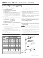
Connect gas supply piping
6. Pipe joint compound (pipe dope) must be resistant to corrosive action of liquefied petroleum gases. Apply sparingly
only to make threads of pipe joints.
Connecting gas supply piping
1. Size gas piping considering:
a) Diameter and length of gas supplying piping.
b) Number of fittings.
c) Maximum gas consumption (including any possible future
expansion).
d) Allowable loss in gas pressure from gas meter outlet to boiler. For
PRESSUREDROPSSEE!.3):#ANADIANINSTALLATIONSMUST
comply with CAN/CSA B149.1 or B149.2 Installation Codes.
2. For natural gas:
a) Refer to Table 11 or the National Fuel Gas Code. To obtain cubic
feet per hour, divide the input by 1000.
b) Size for rated boiler input.
c) Inlet gas pressure:
5” W.C. minimum
13” W.C. maximum
d) Manifold gas pressure: 3¹⁄₂" W.C.
e) Install 100% lock-up gas pressure regulator in supply line if inlet
pressure exceeds 13" W.C., then adjust for 13" W.C. maximum.
3. For propane gas:
11” W.C. minimum
13” W.C. maximum
b) Manifold gas pressure: 10” W.C.
c) Gas pressure regulator provided by gas supplier must be adjusted
for maximum pressure of 13” W.C.
d) Contact gas supplier to size pipes, tanks and regulator.
7. Install drip leg at inlet of gas connection to boiler. Where local
utility requires, extend drip leg to floor.
8. Install ground joint union when required for servicing. See
Figure 26.
9. Install manual shut-off valve outside boiler jacket as shown
in Figure 26 when required by local codes.
10. Support piping by hangers, not by boiler or its accessories.
11. In Canada only, the manual main shut off valve (when used)
must be identified by the installer.
12. Purge all air from piping.
13. Before placing boiler in operation, check boiler and its gas
connection for leaks.
a) Inlet gas pressure:
4. Remove knock-out disc from jacket panel which gas supply
is to be piped.
5. Follow good piping practices.
4ABLE
Adjusted
length
of gas
supply
piping in
feet *
a) Close manual main shut-off valve during any pressure testing
at less than 13 inches water column.
b) Disconnect boiler and gas valve from gas supply piping during
any pressure test greater than 13 inches water column.
&IGURE Gas supply piping
Gas pipe capacities
Capacity of pipe for pipe sizes in
cubic feet of gas per hour **
½”
¾”
1”
1¼”
1½”
2”
10
132
278
520
1050
1600
3050
20
92
190
350
730
1100
2100
30
73
152
285
590
860
1650
40
63
130
245
500
760
1450
50
56
115
215
440
670
1270
75
45
93
175
360
545
1020
100
38
79
150
305
460
870
150
31
64
120
250
380
710
Notes
$ONOTCHECKFORGASLEAKSWITHANOPENmAMEnUSE
bubble test. Failure to do so can cause severe personal injury, death or substantial property damage.
* Include measured length of gas supply piping and allowance
in feet for number and size of fittings.
** Specific Gravity - 0.60; Pressure loss - 0.30” w.c.
22
Part Number 550-142-782/1112
EG & PEG
SERIES
5sEGH
SERIES
5
GAS-FIRED BOILERS
—
BOILER MANUAL
For your safety, turn off electrical power supply at service entrance panel before making any electrical connections to avoid possible electric shock hazard. Failure to do so can cause severe personal injury or death.
Refer to the Control Supplement for additional
information, operating instructions and control
wiring diagram.
Wiring must be N.E.C. Class 1.
If rollout thermal fuse element wire supplied with
boiler must be replaced, type 200 °C wire or equivalent must be used. If other original wiring supplied
with boiler must be replaced, use only type 105 °C
wire or equivalent.
Boiler must be electrically grounded as required
BY.ATIONAL%LECTRICAL#ODE!.3).&0!nLATEST
edition.
5. Multiple zones — Refer to zone valve manufacturer’s literature
for wiring and application. A separate transformer is required
TOPOWERZONEVALVES:ONINGWITHCIRCULATORSREQUIRESARELAY
for each circuit.
Room thermostat
1. Connect thermostat as shown on wiring diagram on boiler.
2. Install on inside wall away from influences of drafts, hot or
cold water pipes, lighting fixtures, television, sunrays or fireplaces.
3. If thermostat has a heat anticipator, set heat anticipator in
thermostat to match power requirements of equipment connected to it. Refer to the appropriate Control Supplement for
instructions on the thermostat anticipator setting.
&IGURE Provide strain relief
Electrical installation must comply with:
1. National Electrical Code and any other national, state, provincial or local codes or regulations.
2. In Canada, CSA C22.1 Canadian Electrical Code Part 1, and
any local codes
Wiring connections
1. Boiler is shipped with controls completely wired, except
spill switch and vent damper. See wiring diagram in Control
Supplement for details.
2. Installer must attach wiring diagram inside jacket door.
3EE&IGUREFORlELDWIRING!SEPARATE6!#ELECTRICAL
circuit with a fused disconnect switch (15 amp recommended)
should be used for the boiler.
4. A strain relief bushing and adapter must be used at each point
where wiring passes through control case (see Figure 27) to
protect wiring insulation.
DHW (if used)
Connect the DHW aquastat as shown in wiring below. The
Economy function of the control is not utilized with DHW
input.
R & C Connections (if used)
6!#LEADSSHOULDBEUSEDFORPOWERSTEALINGTHERMOSTATSONLY
/THERDEVICESREQUIRING6!#SHOULDHAVESEPArate power supply.
&IGURE Connect field wiring in boiler junction box as shown below. See Control Supplement for more details.
Part Number 550-142-782/1112
23
EG & PEG
SERIES
5sEGH
SERIES
5
GAS-FIRED BOILERS
—
BOILER MANUAL
Start-up
Wiring multiple zones
Refer to zone valve manufacturer’s literature for wiring
and application. A separate transformer is required to
POWERZONEVALVES:ONINGWITHCIRCULATORSREQUIRESA
relay for each circulator.
$/./4CONNECTDIRECTLYFROM
WIREZONEVALVESTOTHE44
TERMINALSONTHEBOILER. When
using 3-wire zone valves, install an
isolation relay. Connect the zone
valve end switch wires to the isolation
relay coil. Connect the isolation
relay contact across the boiler T-T
terminals. Failure to comply can result
in damage to boiler components or
cause unreliable operation, resulting
in severe property damage.
Check for gas leaks
Do not use petroleum-based cleaning or sealing compounds
in boiler system. Severe damage to boiler will occur, resulting
in substantial property damage.
Eliminate all system leaks. Continual fresh makeup water will
reduce boiler life. Minerals can build up in sections, reducing
heat transfer, overheating cast iron, and causing section failure.
Consult local water treatment companies for unusually hard water areas
(above 7 grains hardness) or low pH water conditions (below 7.0). Boiler
water pH of 7.0 to 8.5 is recommended.
Freeze protection (when used)
Use antifreeze especially made for hydronic systems. Inhibited propylene
glycol is recommended.
Do not use automotive, ethylene glycol or undiluted antifreeze.
Severe personal injury, death or substantial property damage
can result.
A 50% glycol solution provides protection to about -30°F.
Local codes may require back-flow preventer or actual disconnect from
city water supply.
Before starting the boiler, and during initial
operation, smell near the floor and around
Determine quantity according to system water content. Boiler water content
is listed on page 38. Remember to add in expansion tank water content.
the boiler for gas odorant or any unusual
odor. Do not proceed with start-up if
there is any indication of a gas leak. Repair
any leak at once.
Propane boilers only — Your propane supplier mixes an odorant with the propane
to make its presence detectable. In some
instances, the odorant can fade and the
gas may no longer have an odor.
Follow antifreeze manufacturer’s instructions.
s 0ROPANE GAS CAN ACCUMULATE AT mOOR LEVEL
Smell near the floor for the gas odorant or
any unusual odor. If you suspect a leak, do not
attempt to light the pilot.
s 5SECAUTIONWHENATTEMPTINGTOLIGHTTHEPROpane pilot. This should be done by a qualified
service technician, particularly if pilot outages
are common.
s 0ERIODICALLY CHECK THE ODORANT LEVEL OF YOUR
gas.
s )NSPECT BOILER AND SYSTEM AT LEAST YEARLY TO
make sure all gas piping is leak-tight.
s #ONSULT YOUR PROPANE SUPPLIER REGARDING
installation of a gas leak detector. There are
some products on the market intended for this
purpose. Your supplier may be able to suggest
an appropriate device.
Fill the system
Do not fill (except for leakage tests) until
the boiler is ready to be fired.
Filling water systems
1. Close manual air vents, drain cock, and automatic air vent, if used.
2. Fill to correct system pressure. Correct pressure will vary with each
application. Residential systems are often designed for 12 psig of cold
fill pressure.
3. Open automatic air vent one turn, if used.
4. Open manual water feed valve.
a) Starting on lowest floor, open air vents one at a time until water squirts
out. Close vent.
b) Repeat with remaining vents.
5. Close manual water feed valve when correct boiler pressure is reached.
6. If purge valve is used - located in the return piping above isolation valve:
a) Connect hose to purge valve.
b) Close isolation valve. Open purge valve.
c) Open hand water feed valve and allow system to purge all air. If system
has more than one circuit, purge each circuit separately by opening each
balancing valve one at a time.
d) Close purge valve and water feed valve cock.
e) Open isolation valve.
f) Fill system to correct pressure.
Filling steam boilers
1. Fill to normal waterline, halfway up gauge glass.
2. Boiler water pH 7.0 to 8.5 is recommended.
3. Follow skimming procedure.
Determine if water treatment is needed
24
Part Number 550-142-782/1112
EG & PEG
SERIES
5sEGH
SERIES
5
GAS-FIRED BOILERS
—
BOILER MANUAL
Start-up (continued)
Skim the steam boiler
Clean all newly installed steam boilers to
remove oil and grease. Failure to properly
clean can result in violent fluctuations
of water level, water passing into steam
mains or high maintenance costs on
strainers, traps and vents.
Do not use petroleum-based cleaning or
sealing compounds in boiler system. Severe damage to boiler will occur, resulting
in substantial property damage.
1. Provide 1½” piping from skim tapping to floor
drain.
2. Adjust waterline to midpoint of skim tapping. See
Figure 5, page 10.
3. Follow “Operating Instructions” in the Control
Supplement to fire boiler to maintain temperature
below steaming rate.
4. Feed in water to maintain water level. Cycle burners
to prevent rise in steam pressure.
5. Continue skimming until discharge is clear. May
take several hours.
6. Drain boiler. While boiler is warm, but not hot, flush
all interior surfaces under full pressure until drain
water runs clear.
7. Remove skim piping. Plug tapping.
8. Close drain cock. Fill with fresh water to waterline.
Start burners and steam for 15 minutes to remove
dissolved gases. Stop burners.
9. Check traps and air vents for proper operation.
10. Process may need to be repeated after several weeks
of operation.
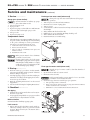
Inspect base insulation
The boiler contains ceramic fiber and
fiberglass materials. Use care when handling these materials per instructions on
page 33 of this manual. Failure to comply
could result in severe personal injury.
Check to make sure insulation is secure against all four
sides of the base. If insulation is damaged or displaced,
do not operate boiler. Replace or reposition insulation.
Failure to replace damaged insulation or
reposition insulation can result in a fire
hazard, causing severe personal injury,
death or substantial property damage.
Operate boiler
Check system and boiler
DO NOT proceed with boiler operation unless boiler and
system have been filled with water and all instructions and
procedures of previous manual sections have been completed.
Failure to do so could result in severe personal injury, death
or substantial property damage.
Before starting the boiler . . .
s 3EE#ONTROL3UPPLEMENTFORhOperating Instructions”.
s 6ERIFYTHEBOILERANDSYSTEMWATERLEVELISCORRECT3TEAMNO
more than ½ of gauge glass or less than ¼” above bottom of
gauge glass).
s 6ERIFY THEh0REPARATIONv PROCEDURES ON THE PREVIOUS PAGES
have been completed.
Start the boiler
1. Steam boilers — Check boiler water level — Should be approximately
½ way up gauge glass.
2. Remove boiler jacket door and note the gas valve manufacturer and
model number.
3. Follow the Lighting or Operating Instructions in the Control Supplement, depending on gas valve installed in boiler. Use only the Operating
Instruction which applies to this gas valve. (The Operating Instruction
label on the boiler provides the same information.)
4. If boiler fails to start, see “If boiler doesn’t start . . . Check for:” on the
next page.
Check system and boiler
Eliminate all system leaks. Continual fresh makeup water will
reduce boiler life. Minerals can build up in sections, reducing
heat transfer, overheating cast iron, and causing section failure.
If you discover evidence of any gas leak, shut down the boiler
at once. Find the leak source with bubble test and repair immediately. Do not start boiler again until corrected. Failure
to comply could result in severe personal injury, death or
substantial property damage.
Do not use petroleum-based cleaning or sealing compounds
in boiler system. Severe damage to boiler will occur, resulting
in substantial property damage.
1. Check system piping for leaks. If found, shut down boiler and repair
immediately.
2. Inspect vent system thoroughly for signs of deterioration from corroSIONPHYSICALDAMAGEORSAGGING6ERIFYTHATMASONRYCHIMNEYLINERS
are in good condition, with no obstructions, and there are no openings
into the chimney.
3. Check around the boiler for gas leaks following the procedure of step 13,
page 22.
6ERIFYOPERATIONUSINGPROCEDURESBELOW0ERFORMh#HECKOUTPROCEdure”, page 27, and fill in the “Installation and Service Certificate”.
Part Number 550-142-782/1112
25
EG & PEG
SERIES
5sEGH
SERIES
5
GAS-FIRED BOILERS
—
BOILER MANUAL
Start-up (continued)
If boiler doesn’t start . . . Check for:
1. Loose connections, blown fuse or service switch off?
2. High limit switch set below boiler pressure?
3. Thermostat set below room temperature?
4. Gas not turned on at meter or boiler?
5. Incoming gas pressure less than:
5” w.c. for natural gas? 11” w.c. for propane gas?
6. If none of the above corrects the problem, see
“Troubleshooting” in the Control Supplement.
&IGURE Typical pilot burner flame
Verify operation
Check burner flame — Pilot burner
1. Proper pilot flame (see Figure 28):
a. Blue flame.
b. Inner cone engulfing thermocouple.
c. Thermocouple glowing cherry red.
2. Proper pilot flame:
&IGURE Typical main burner flame
a. Overfired — Large flame lifting or blowing past
thermocouple.
b. Underfired — Small flame. Inner cone not engulfing
thermocouple.
c. Lack of primary air — Yellow flame tip.
d. Incorrectly heated thermocouple.
Check burner flame — Main burner
1. Proper main burner flame (see Figure 29):
a. Yellow-orange streaks may appear (caused by dust).
2. Improper main burner flame:
a. Overfired — Large flames.
b. Underfired — Small flames.
c. Lack of primary air — Yellow tipping on flames (sooting will occur).
Check vent damper operation
2AISE ROOM THERMOSTAT TO CALL FOR HEAT 6ENT
damper actuator will slowly open vent damper.
2. 7HENVENTDAMPERISFULLYOPEN — Pilot will light,
then allow main burners to ignite.
4. Repeat Steps 2 through 4 several times to verify
operation.
5. Return thermostat to normal setting.
6. Set thermostat heat anticipator setting indicated on
wiring diagram.
6ENT DAMPER MUST BE FULLY OPEN BEFORE
main burners light. If vent damper does
not fully open, flue products such as
carbon monoxide will escape into house,
causing severe personal injury or death.
Check venting system operation
With boiler firing, hold a candle or match below lower
edge of draft diverter “skirt.” If flame does not blow
out, but burns undisturbed, the vent system is working
properly. If flame blows out or flickers severely, the vent
system must be checked for obstructions or other causes
of improper venting.
3. Lower thermostat setting — Main burner flames
will go out, then vent damper will close.
26
Part Number 550-142-782/1112
EG & PEG
SERIES
5sEGH
SERIES
5
GAS-FIRED BOILERS
—
BOILER MANUAL
Start-up (continued)
❏
Check-out procedure
Check-off steps as completed.
❏ System properly filled with water?
❏
❏
Automatic air vent, if used, open one turn (water boilers only)?
❏
Air purged from system (water boilers only)?
❏
Steam boilers properly skimmed?
❏
❏
Air purged from gas piping? Piping checked for leaks?
❏
❏
Are proper orifices installed? Check page 11 for proper size.
Proper orifices must be used. Failure to do so will
cause severe personal injury, death or substantial
property damage.
❏
❏
❏
❏
❏
❏
Follow operating instruction label on boiler for proper startup. Also refer to “Operate boiler,” page 25.
Proper burner flame? See “Check burner flame — Main
burner” and “Check burner flame — Pilot burner,” page 26.
Test temperature limit — While burners are operating, turn
Boiler Temp adjustment knob counterclockwise until display
reading is below actual boiler water temperature. Burners
should go off while circulator continues to operate (water
boilers only). Turn Boiler Temp adjustment knob clockwise
until display reading is above boiler water temperature and
ignition sequence should resume.
Test any additional field-installed controls: If boiler has a low
water cut-off, additional high limit or other controls, test for
operation as outlined by manufacturer. Burners should be
operating and should go off when controls are tested. When
controls are restored, burners should reignite.
EG only - button on spill switch pushed in?
To test ignition system shut-off device:
Connect manometer to outlet side of gas valve. Start boiler, allowing for normal start-up cycle to occur and main burners to ignite.
With main burners on, manually shut off gas supply at manual
main shutoff gas valve. Burners should go off. Open manual main
shut-off gas valve. Manometer should confirm there is no gas flow.
Pilot will relight, flame sensing element will sense pilot flame and
main burners reignite.
❏
❏
Set Boiler Temp adjustment knob to system temperature
requirements. Adjust balancing valves and controls to provide design temperature to system. (water boilers)
Limit control set to design temperature or pressure requirements of system? Maximum limit setting - 240°F - 15#
(steam boilers).
For multiple zones, flow adjusted so it is about the same in
each zone (water boilers only)?
Thermostat heat anticipator set properly? Refer to “Room
Thermostat,” page 20 and correct wiring diagram.
Boiler cycled with the thermostat? Raise to highest setting.
Boiler should go through normal start-up cycle. Lower to
lowest setting. Boiler should go off.
Measure gas input (natural gas only):
a. Operate boiler 10 minutes.
b. Turn off other appliances.
c. At the natural gas meter, measure time (in seconds) required to
use one cubic foot of gas.
d. Calculate gas input:
3600 x 1000
= Btuh
number of seconds from step c
e. Btuh calculated should approximate input rating on rating label.
❏
❏
❏
❏
❏
Check manifold gas pressure by connecting a manometer
to the downstream test tapping on main gas valve.
MANIFOLD GAS PRESSURE
NAT. = 3.5" W.C.
L.P. = 10.0" WC.
Several operating cycles observed for proper operation? If
damper is provided, see Control Supplement for check- out
procedure.
Room thermostat set to desired temperature?
Installation and Service Certificate on this page completed?
All instructions shipped with this boiler reviewed with
owner or maintenance person, returned to envelope and
given to owner or displayed near boiler?
Installation and service certificate
Boiler model __________________
Series __________
CP number ___________
Date installed ___________
Measured Btuh input ____________________
Installer ________________________
(company)
❏ Installation instructions have been followed.
❏ Check out sequence has been performed.
❏ Above information is certified to be correct.
❏ Information received and left with
owner/maintenance person
________________________________
________________________
(address)
(phone)
Installer’s signature: _____________________________________
Part Number 550-142-782/1112
27
EG & PEG
SERIES
5sEGH
SERIES
5
GAS-FIRED BOILERS
—
BOILER MANUAL
Department of Energy – Compliance
EG water boilers only
This boiler is equipped with a control system that automatically adjusts a time delay period to turn on the boiler
during a call for heat. This is accomplished by circulating available hot water in the system while measuring
water boiler water temperature changes. The control calculates a suitable delay based on temperature measurements and turns the boiler on only after it determines that the demand for heat cannot be satisfied with the
available hot water,
Due to the wide variety of controls used in boiler installations, this control is also equipped with an adjustment
for the calculated time delay period (ECONOMY ADJUST). In the MIN position, the time delay is zero and the
IMPORTANT notice below must be observed:
IMPORTANT
In accordance with Section 325 (f) (3) of the Energy Policy and Conservation Act, this boiler is equipped with
a feature that saves energy by reducing the boiler water temperature as the heating load decreases. This feature
is equipped with an override which is provided primarily to permit the use of an external energy management
system that serves the same function.
4()3/6%22)$%-534./4"%53%$5.,%33!4,%!34/.%/&4(%&/,,/7).'#/.$)4)/.3)3425%
s An external energy management system is installed that reduces the boiler water temperature as the heating load
decreases.
s This boiler is part of a modular or multiple boiler system having a total input of 300,000 BTU/hr or greater.
s This boiler is equipped with a tankless coil.
28
Part Number 550-142-782/1112
EG & PEG
SERIES
5sEGH
SERIES
5
GAS-FIRED BOILERS
—
BOILER MANUAL
Service and maintenance
4ABLE 3ERVICEANDMAINTENANCESCHEDULESSERVICETECHNICIANANDOWNER
Service technician
Owner maintenance
(see following pages for instructions)
(see User’s Information Manual for instructions)
Daily
s Check boiler area
Inspect:
s Check air openings
s Reported problems
s Check boiler pressure/
s Boiler area
temperature gauge
s Air openings
s Flue gas vent system
Monthly
s Check boiler interior piping
s Pilot and main burner flames
s Check venting system
ANNUAL
START-UP
s Piping
s Check air vents
s Boiler heating surfaces
s Check boiler relief valve
s Burners and base
s Check pilot and main burner flames
Service:
s Gauge glass
s Temperature sensor
Start-up:
Periodically
s Test low water cutoff (if used)
s Perform start-up per manual
s EGH - Check base insulation & fastener clips
End of season
s Shut down procedure
Check/test:
s Gas piping
s Boiler waterline
s Limit controls and cutoffs
s Boiler relief valve
Review:
s Review with owner
Follow the “Service and maintenance” procedures given throughout this manual, the Control Supplement and in component literature shipped with the boiler. See “Read this page first” on page 2. Failure to perform the service and maintenance could result in damage to the boiler or system. Failure to follow the directions in this manual and component
literature could result in severe personal injury, death or substantial property damage.
Label all wires prior to disconnection when servicing controls. Wiring errors can cause improper and
dangerous operation.
To avoid personal injury, death or property damage,
keep boiler area clear and free from combustible
materials, gasoline and other flammable vapors
and liquids.
Part Number 550-142-782/1112
Do not block flow of air to boiler. Incomplete
combustion and flue gas spillage can occur.
Do not store sources of hydrocarbons (i.e., bleaches,
cleaners, chemicals, sprays, paint removers, fabric
softeners, etc.) in boiler area. This can contribute
to shortened boiler/vent system life.
29
EG & PEG
SERIES
5sEGH
SERIES
5
GAS-FIRED BOILERS
—
BOILER MANUAL
Service and maintenance (continued)
The boiler should be inspected and started annually, at the beginning of the heating season, only
by a qualified service technician. In addition, the
maintenance and care of the boiler designated in
Table 12, page 29 and explained on the following
pages must be performed to assure maximum
boiler efficiency and reliability. Failure to service
and maintain the boiler and system could result in
equipment failure.
Electrical shock hazard — Turn off power to the
boiler before any service operation on the boiler
except as noted otherwise in this manual. Failure
to turn off electrical power could result in electrical
shock, causing severe personal injury or death.
The boiler contains ceramic fiber and fiberglass
materials. Use care when handling these materials
per instructions on page 33 of this manual. Failure
to comply could result in severe personal injury.
Inspect . . . . . . . . . .
Reported problems
Inspect any problems reported by owner and correct before
proceeding.
Boiler area
6ERIFYTHATBOILERAREAISFREEOFANYCOMBUSTIBLEMATERIALS
gasoline and other flammable vapors and liquids.
6ERIFYTHATBOILERAREAISFREEOFANYOFTHECONTAMINANTSLISTED
on page 7 of this manual. If any of these are present in the
boiler intake air vicinity, they must be removed. If they cannot be removed, install combustion air piping to the boiler
in accordance with national, provincial or local codes.
Air openings
6ERIFYTHATCOMBUSTIONANDVENTILATIONAIROPENINGSTOTHE
boiler room and/or building are open and unobstructed.
Check operation and wiring of automatic combustion air
dampers, if used.
6ERIFYTHATBOILERVENTDISCHARGEANDAIRINTAKEARECLEANAND
free of obstructions.
Flue gas vent system
6ISUALLYINSPECTENTIREmUEGASVENTINGSYSTEMFORBLOCKAGE
deterioration or leakage. Repair any joints that show signs of
leakage in accordance with vent manufacturer’s instructions.
6ERIFY THAT MASONRY CHIMNEYS ARE LINED LINING IS IN GOOD
condition, and there are not openings into the chimney.
Failure to inspect for the above conditions and have
them repaired can result in severe personal injury
or death.
Pilot and main burner flames
6ISUALLYINSPECTPILOTBURNERANDMAINBURNERmAMESASDIRECTED
on page 26 of this manual.
30
Piping
1. Check the boiler interior piping and all system piping for signs
of leaks. Repair any leaks before proceeding.
Do not use petroleum-based cleaning or sealing
compounds in boiler system. Severe damage to
boiler will occur, resulting in substantial property
damage.
Eliminate all system or boiler leaks. Continual
fresh makeup water will reduce boiler life. Minerals
can build up in sections, reducing heat transfer,
overheating cast iron, and causing section failure.
Leaking water may also cause severe property
damage.
Boiler heating surfaces
The boiler contains ceramic fiber and fiberglass
materials. Use care when handling these materials
per instructions on page 33 of this manual. Failure
to comply could result in severe personal injury.
1. Disconnect the vent pipe at the boiler draft diverter and remove draft diverter after turning off power to the boiler.
2. Use a bright light to inspect the boiler flue collector and heating surfaces.
3. If the vent pipe or boiler interior surfaces show evidence of
soot, follow “Cleaning boiler heating surfaces”, page 30. Remove the flue collector and clean the boiler if necessary after
closer inspection of boiler heating surfaces.
4. If there is evidence of rusty scale deposits on boiler surfaces,
check the water piping and control system to make sure the
boiler return water temperature is properly maintained (per
this manual).
5. Reconnect vent and draft diverter. Replace all boiler components
before returning to service.
6. Check inside and around boiler for evidence of any leaks from
the boiler. If found, locate source of leaks and repair.
Burners and base
1. After turning off power to the boiler, remove the jacket door
and base access panel.
2. Inspect burners and all other components in the boiler base.
3. If burners must be cleaned, raise rear of each burner to release
from support slot, slide forward and remove. Then brush and
vacuum the burners thoroughly, making sure all ports are free
of debris. Carefully replace all burners, making sure burner
with pilot bracket is replaced in its original position and all
burners are upright (ports up).
4. Inspect the base insulation.
A 6ERIFYTHATTHEINSULATIONISINTACTANDSECUREAGAINSTALL FOUR
sides of the base and attachment clips are still in place.
If insulation is damaged or displaced, do not operate the boiler. Replace or reposition insulation as
necessary. Failure to replace damaged insulation
can result in a fire hazard, causing severe personal
injury, death or substantial property damage.
Part Number 550-142-782/1112
EG & PEG
SERIES
5sEGH
SERIES
5
GAS-FIRED BOILERS
—
BOILER MANUAL
Service and maintenance (continued)
❏ 3ERVICE
Probe-type low water cutoff (when used)
Gauge glass (steam boilers)
1.
2.
3.
4.
5.
Normal waterline is halfway up gauge
glass. Clean when needed.
Close lower gauge cock.
Open pet cock.
Open lower gauge cock and allow a small amount
of water to flush out through open pet cock.
Close pet cock.
Open lower gauge cock.
Temperature sensor
1. The temperature sensor may accumulate deposits on
the probe surface. Annual inspection and cleaning
of the probe will improve boiler performance.
1.
2.
3.
4.
5.
6.
7.
8.
Clean probe-type low water cutoff (when used) for proper
operation.
Turn off power to boiler and wait 5 minutes.
Drain water to bottom of gauge glass.
Turn on power.
Set thermostat to call for heat. Red neon lamp on lower water cutoff
should light.
Wait 5 minutes. Boiler should not fire.
Refill boiler to correct waterline. Red lamp should go off.
Wait 5 minutes. Boiler should fire.
Return thermostat to normal setting.
Disconnect power, unplug harness from sensor.
a. Drain boiler water to a level below the sensor.
b. Remove sensor from boiler.
c. Wipe any built up contaminates from probe and
insulator surfaces.
d. Reinstall sensor into boiler
Boiler pressure must be low to eliminate
potential of severe burns.
If gauge glass breaks, close both gauge
cocks. Replace gauge glass. Do not replace
with thin glass tubing. Failure to comply
could cause severe personal injury, death
or substantial property damage.
❏ 3TARTUP
1. Perform “Start-up” procedures in this manual,
PAGESnINCLUDINGh6ERIFYOPERATIONvOFBURNERS
and vent damper on page 26.
2. Check gas piping, per pages 22 and 24, verifying no
indications of leakage and all piping and connections are in good condition.
3. Read the “Lighting Instructions” in the Control
Supplement.
4. Start the boiler following the “Lighting Instructions.”
❏ #HECKTEST
Float-type low water cutoff (when used)
Clean float-type low water cutoff to clear float chamber of
sediment.
1. Open blowdown valve at bottom control.
2. Drain water into a bucket.
Scald potential. Boiler pressure must be low to avoid the
potential of severe burns from steam.
3. Check float-type low water cutoff for proper operation:
a. Turn operating control to call for heat.
b. Before water gets hot, drain to bottom of gauge glass. Boiler should shut
off after water level lowers a few inches.
c. Refill boiler to correct waterline. Boiler should come back on.
Gas piping
1. Sniff near floor and around boiler area for any indication of a gas leak.
2. Test gas piping using bubble test, per page 22 of this
manual, if there is any indication of a leak.
Boiler waterline
Normal waterline is halfway up gauge glass.
Limit controls
)NSPECTANDTESTTHEBOILERLIMITCONTROL6ERIFYOPeration by turning control set point below boiler
pressure. Boiler should cycle off. Return dial to
original setting.
Part Number 550-142-782/1112
31
EG & PEG
SERIES
5sEGH
SERIES
5
GAS-FIRED BOILERS
—
BOILER MANUAL
Service and maintenance (continued)
❏ #HECKTEST
Boiler relief valve
1. After following the warning directions below, if the
relief valve weeps or will not seat properly, replace the
relief valve.
Before testing, make certain discharge pipe
is properly connected to valve outlet and arranged to contain and safely dispose of boiler
discharge. Wear gloves to protect your hands
FROMHOTSURFACES6ERIFYTHATDISCHARGEPIPING
is installed in accordance with this manual
and the instructions on the relief valve tag.
Failure to comply will expose operator and
others to severe personal injury or death.
Safety relief valves should be reinspected AT
,%!34 /.#% %6%29 4(2%%9%!23 BY
a licensed plumbing contractor or authorized inspection agency, to ensure that the
product has not been affected by corrosive
water conditions and to ensure that the valve
and discharge line have not been altered or
tampered with illegally. Certain naturally
occurring conditions may corrode the valve
or its components over time, rendering the
valve inoperative. Such conditions are not
detectable unless the valve and its components are physically removed and inspected.
This inspection must only be conducted by
a plumbing contractor or authorized inspection agency — not by the owner. Failure to
reinspect the boiler relief valve as directed
could result in unsafe pressure buildup, which
can result in severe personal injury, death or
substantial property damage.
Check the setting of the boiler limit control.
The control should never be set with a pressure above 10 psig. Operating at a higher
pressure can cause damage to the boiler relief
valve.
The boiler relief valve must be tested at least
monthly during the heating season to verify
the valve and discharge piping flow freely. If
corrosion and/or deposits are noticed within
the valve body, testing must be performed
more often. A “try lever test” must also be
performed at the end of any non-service
period. Follow the instructions below for a
“try lever test”:
With the system at operating pressure, lift
and hold the test lever fully open for at least 5
seconds to flush the valve seat free of sediment
and debris. Then release lever and permit the
valve to snap shut.
32
❏ 2EVIEWWITHOWNER
1. Review the User’s Information Manual with the owner.
2. Emphasize the need to perform the maintenance schedule specified in the User’s Information Manual (and in this manual as well).
3. Remind the owner of the need to call in a licensed contractor
should the boiler or system exhibit any unusual behavior.
4. Remind the owner to follow the proper shutdown procedure and
to schedule an annual start-up at the beginning of the next heating
season.
❏ #LEANINGBOILERHEATINGSURFACES
The boiler contains ceramic fiber and fiberglass materials. Use care when handling these materials per instructions on page 33 of this manual. Failure to comply could
result in severe personal injury.
1. Follow shut-down procedure
2. Disconnect breeching and remove damper (if used) and draft
hood.
3. Remove upper rear jacket panel. Turn back jacket insulation to
expose collector hood.
4. Remove collector hood. Clean excess boiler cement from collector
hood and cast iron sections.
5. Remove burners from base of boiler. Follow “Cleaning main
burners” to thoroughly clean burners. Place newspaper in base
of boiler to collect soot that will fall.
6. With a wire flue brush, clean between the sections.
2EMOVEPAPERANDSOOT6ACUUMORBRUSHBASEANDSURROUNDING
area.
8. Replace collector hood. Seal with boiler cement.
9. Replace draft hood, damper (if used) and breeching.
10. Replace insulation and jacket panel.
11. Replace main burners.
Cleaning main burners
6ACUUMORBRUSHBURNERSTOREMOVEDUSTANDLINT
When replacing, burner tubes must be seated in slots in
the back with openings face up. Gas orifices must inject
down center of burner. Failure to properly seat burners
will result in severe personal injury, death or substantial
property damage.
Annual shut-down procedure
1. Follow correct operating instructions on boiler.
2. Do not drain system unless exposure to freezing temperatures will
occur. If antifreeze is used with system, do not drain.
3. If complete boiler and piping system must be drained to avoid
freezing, provide method to drain water from both ends of boiler
at or below return tapping level.
Part Number 550-142-782/1112
EG & PEG
SERIES
5sEGH
SERIES
5
GAS-FIRED BOILERS
—
BOILER MANUAL
REMOVAL OF COMBUSTION CHAMBER LINING OR BASE PANELS
The combustion chamber lining or base insulation panels in this product contain ceramic fiber
materials. Ceramic fibers can be converted to cristobalite in very high temperature applications. The International Agency for Research on Cancer (IARC) has concluded, “Crystalline
silica inhaled in the form of quartz or cristobalite from occupational sources is carcinogenic
to humans (Group 1).”:
■ Avoid breathing dust and contact with skin and eyes.
s 5SE.)/3(CERTIlEDDUSTRESPIRATOR.4HISTYPEOFRESPIRATORISBASEDONTHE
OSHA requirements for cristobalite at the time this document was written. Other types
of respirators may be needed depending on the job site conditions. Current NIOSH
recommendations can be found on the NIOSH web site at http://www.cdc.gov/niosh/
homepage.html. NIOSH approved respirators, manufacturers, and phone numbers are
also listed on this web site.
s 7EARLONGSLEEVEDLOOSElTTINGCLOTHINGGLOVESANDEYEPROTECTION
■ Apply enough water to the combustion chamber lining or base insulation to prevent airborne dust.
■ Remove combustion chamber lining or base insulation from the boiler and place it in a
plastic bag for disposal.
■ Wash potentially contaminated clothes separately from other clothing. Rinse clothes washer
thoroughly.
NIOSH stated First Aid.
■ Eye: Irrigate immediately.
■ Breathing: Fresh air.
REMOVAL OF FIBERGLASS WOOL — OR —
INSTALLATION OF FIBERGLASS WOOL, COMBUSTION CHAMBER
LINING OR BASE PANELS:
This product contains fiberglass jacket insulation and ceramic fiber materials in combustion
chamber lining or base panels in gas fired products. Airborne fibers from these materials have
been listed by the State of California as a possible cause of cancer through inhalation.
■ Avoid breathing dust and contact with skin and eyes.
s 5SE.)/3(CERTIlEDDUSTRESPIRATOR.4HISTYPEOFRESPIRATORISBASEDONTHE
OSHA requirements for fiberglass wool at the time this document was written. Other
types of respirators may be needed depending on the job site conditions. Current
NIOSH recommendations can be found on the NIOSH web site at http://www.cdc.
gov/niosh/homepage.html. NIOSH approved respirators, manufacturers, and phone
numbers are also listed on this web site.
s 7EARLONGSLEEVEDLOOSElTTINGCLOTHINGGLOVESANDEYEPROTECTION
■ Operations such as sawing, blowing, tear out, and spraying may generate airborne fiber
concentration requiring additional protection.
■ Wash potentially contaminated clothes separately from other clothing. Rinse clothes washer
thoroughly.
NIOSH stated First Aid.
■ Eye: Irrigate immediately.
■ Breathing: Fresh air.
Part Number 550-142-782/1112
33
EG & PEG
SERIES
5sEGH
SERIES
5
GAS-FIRED BOILERS
—
BOILER MANUAL
Replacement parts — EG/PEG
4ABLE
Item
A
B
C
D
E
EG/PEG replacement parts
Description
Boiler
Models
:
*B@y@Q
:
*B@y@K
{
*B@y@@y
––
^
*B@y@X
––
Draft hood
Collector hood
––
––
Part Number
Item
311-800-014
H
Description
Boiler
Models
Part Number
EG-30, 35
451-800-000
EG-40, 45
451-800-001
EG-50, 55
451-800-002
311-800-029
EG-65
451-800-003
311-800-010
EG-75
451-800-004
Front base panel
311-800-007
EG-30
450-021-255
EG-35
450-021-256
EG-40
450-021-257
EG-45
450-021-258
EG-50
H1
,(includes front and rear base panel
&
&
––
510-811-660
EG-30, 35
451-800-040
EG-40, 45
451-800-041
EG-50
451-800-039
450-021-259
EG-55
451-800-042
EG-55
450-021-260
EG-65
451-800-043
EG-65
450-021-261
EG-75
451-800-044
EG-75
450-021-262
EG-30
451-800-085
EG-34
451-800-086
EG-40
451-800-087
EG-45
451-800-088
EG-50
451-800-089
EG-55
451-800-090
EG-65
451-800-092
EG-75
451-800-094
EG-30, 35
451-800-010
EG-30, 35
H2
H3
bracket
,
450-014-733
EG-40, 45
450-014-734
EG-50, 55
450-014-735
EG-65
450-014-736
EG-75
450-014-737
F
&
&
––
512-200-000
F1
&
&
,
––
512-200-001
G
Manifold
EG-30
591-125-533
EG-40, 45
451-800-011
EG-35
591-125-538
EG-50, 55
451-800-012
EG-40
591-125-534
EG-65
451-800-013
591-125-539
EG-75
451-800-014
EG-30, 35
451-800-020
EG-40, 45
451-800-021
EG-50, 55
451-800-022
EG-65
451-800-023
EG-75
451-800-024
––
451-800-070
EG-45
EG-50
EG-55
`
)&
&IBQX@
`
)&
&@BXX@
591-125-535
I2
,
,
591-125-540
EG-65
591-125-541
EG-75
591-125-542
––
560-528-987
––
I
560-528-988
J
IF
K
––
510-300-013
L
!
––
389-900-103
––
590-317-579
EG-30, 35
321-811-095
EG-35
321-811-100
L2
+
,
EG-40, 45
321-811-110
L3
!
––
389-900-101
L4
+
,
––
590-317-495
––
381-800-667
EG-40, 45
EG-50, 55
321-811-120
Section replacement kit (includes 3” and 6” elasto
&I&&@
}
EG-50, 55
321-811-125
K>'
@}
––
592-800-010
321-811-130
j>'
@}
––
592-800-007
––
591-641-865
321-811-115
EG-65
EG-65
321-811-135
I&
}
EG-75
321-811-140
~>"@Q>I
EG-75
321-811-145
{@F
––
591-602-913
~>"I]>I
EG-65
560-234-485
(
––
591-706-214
~>"K@>I EG-75
560-234-490
~>*I
––
561-928-221
~>:,
@
––
562-248-668
EG-30, 35
560-234-470
~>"@y~>I EG-40, 45
560-234-475
~>"II>I EG-50, 55
560-234-480
*@<)F
)
B
34
Part Number 550-142-782/1112
EG & PEG
SERIES
5sEGH
SERIES
5
GAS-FIRED BOILERS
—
BOILER MANUAL
Replacement parts — EG/PEG (continued)
The boiler contains ceramic fiber and fiberglass materials. Use care when handling these materials per instructions on
page 33 of this manual. Failure to comply could result in severe personal injury.
Part Number 550-142-782/1112
35
EG & PEG
SERIES
5sEGH
SERIES
5
GAS-FIRED BOILERS
—
BOILER MANUAL
Replacement parts — EGH
4ABLE
Item
A
B
C
C1
EGH replacement parts
Description
:
*B@y@Q
Boiler
Models
––
:
*B@y@K
––
{
*B@y@\
––
{
*B@y@@y
––
^
*B@y@X
––
^
*B@y@]
––
K>'
@}
––
j>'
@}
––
D
(
@}
––
E
Draft hood
F
Collector hood
G
&
&
G1
&
&
,
H
Manifold
Item
311-800-014
L1
!
––
389-900-103
+
,
––
311-800-007
L2
590-317-579
L3
!
––
389-900-101
L4
+
,
––
590-317-495
311-800-022
Description
Boiler
Models
Part Number
EGH-85
321-711-100
EGH-85
321-711-105
EGH-95
321-711-110
EGH-95
321-711-115
592-800-007
EGH-105
321-711-120
311-800-032
311-800-010
311-800-026
592-800-010
460-003-790
EGH-105
321-711-125
EGH-85
450-206-240
EGH-115
321-711-130
EGH-95
450-206-241
EGH-105
450-206-242
EGH-115
321-711-135
EGH-115
450-206-243
EGH-125
321-711-140
EGH-125
450-206-244
EGH-85
450-014-750
EGH-125
321-711-145
EGH-95
450-014-751
––
381-800-667
EGH-105
450-014-752
EGH-115
450-014-753
EGH-125
450-014-754
––
512-200-000
––
EGH-85
EGH-95
Section replacement kit (includes 3” and 6”
&I&&
@}
M
512-200-001
591-125-543
591-125-544
{
:#:
{
EGH-105
591-125-545
N
EGH-115
591-125-546
P
{
EGH-125
591-125-547
Q
`
)&
&IBKW@
––
`
)&
&@BQW@
I
EGH-85
451-800-120
EGH-95
451-800-121
EGH-105
451-800-122
EGH-115
451-800-123
EGH-125
451-800-124
––
591-222-183
––
421-800-208
EGH-85
451-800-136
560-528-975
EGH-95
451-800-137
––
560-528-972
EGH-105
451-800-138
(
––
––
EGH-115
451-800-139
I1
(
––
––
EGH-125
451-800-140
I2
––
––
I&
}
––
591-641-865
~>"]>I
––
560-234-465
~>"@]>QqJ+$#yX
IqJ+$#\X
––
560-234-472
~>"I@>IqJ+$#\X
IqJ+$#@@X
QqJ+$#@IX
––
560-234-477
~>"IX>IqJ+$#@@X
QqJ+$#@IX
––
560-234-482
~>*I
––
561-928-221
~>:,
@
––
562-248-668
{@F
––
591-602-913
Flue brush ––
591-706-214
not
I, I1
I2, J,
J1, &
J2
EGH-85
381-700-240
EGH-95
381-700-245
EGH-105
381-700-250
EGH-115
381-700-255
EGH-125
381-700-260
J
,
––
––
J1
,
––
––
K
,
––
451-800-070
K1
,
EGH-85
EGH-95
EGH-105
EGH-115
EGH-125
36
Part Number
451-800-095
451-800-096
451-800-097
451-800-098
451-800-099
*@<)F
)
B
Part Number 550-142-782/1112
EG & PEG
5sEGH
SERIES
SERIES
5
GAS-FIRED BOILERS
—
BOILER MANUAL
Replacement parts — EGH (continued)
The boiler contains ceramic fiber and fiberglass materials. Use care when handling these materials per instructions on
page 33 of this manual. Failure to comply could result in severe personal injury.
E
D
C1
F
B
A
C
J1
P
J
G
M
Q
N
K1
K
H
I
I1
L4
L3
I2
L2
L1
Part Number 550-142-782/1112
37
EG & PEG
SERIES
5sEGH
SERIES
5
GAS-FIRED BOILERS
—
BOILER MANUAL
Dimensional data
4ABLE
Dimensional data
Gas Connection
“F”
Dimensions
Draft hood
outlet size
Approx.
ship. wt.
Model
number
Supply
EG/EGH
Supply
EG/EGH
W
A
B
B1
V I
T
@
EG & PEG-30 & -35
1 - 3”
1 - 2 ½”
17”
5”
11 ¾”
6 ¾”
6”
½”
5”
430
EG & PEG-40 & -45
1 - 3”
1 - 2 ½”
21 ¼”
6”
11 ¾”
6 ¾”
6 ½”
½”
6”
505
EG & PEG-50 & -55
1 - 3”
1 - 2 ½”
25 ½”
7”
11 ¾”
6 ¾”
9”
½”
7”
585
EG & PEG-65
1 - 3”
1 - 2 ½”
29 ¾”
8”
11 ¾”
6 ¾”
9 ½”
;
tankless coil
removal
clearance:
E-624: 14”
E-626: 18”
¾”
8”
660
E-632: 22”
KJ+#KWJ+#XX
EG-75
1 - 3”
1 - 2 ½”
34”
8”
15 ¾”
8 ¾”
––
¾”
8”
735
EGH-85
2 - 3”
2 - 2 ½”
38 ¼”
9”
15 ¾”
8 ¾”
––
¾”
9”
825
EGH-95
2 - 3”
2 - 2 ½”
42 ½”
10”
15 ¾”
8 ¾”
––
¾”
10”
915
EGH-105
2 - 3”
2 - 2 ½”
46 ¾”
10”
15 ¾”
8 ¾”
––
1”
10”
1005
EGH-115
2 - 3”
2 - 2 ½”
51”
12”
15 ¾”
8 ¾”
––
1”
12”
1095
EGH-125
2 - 3”
2 - 2 ½”
55 ¼”
12”
15 ¾”
8 ¾”
––
1”
12”
1185
1. Z
Z&
F)
B+
Z
FB+
line can enter on either the right or left end of the boiler.
2. '
J+#KWJ+#jX<*:B(J+#]X
J+$
FB
3. J+
KI>"K\>B!
KI>J+#KW&#KX&#QW?K]>J+#QX&#XW&
#XX?K\>J+#jXB
Notes:
Tapping
C
Steam Boilers
Water Boilers - EG only
#
D
¾
Drain
Drain
E
¾
G
¾
Plugged
Piping to compression tank or auto air vent
H
½
+
:;!<
J
=
½
L
38
Size
¾
Notes
N/A
:;!<
Tapping
P
(EGH Only)
S
Size
1
1½
¾
Steam Boilers
Water Boilers - EG only
F
:;!<&
?:;!<
?:;!<
(
:;!<?:;!<
?:;!<
Skim tapping
:
qq@
:
T1
––
<
,
Combination pressure temperature gauge
T2
––
<
,
J+$
Tri cock tappings
Plugged
T3
<
,
––
&
&
:;!<
Combination pressure temperature gauge
1. %
F&
,
)B
Z
Notes
`
#
2. ;
,
&
operating control.
Part Number 550-142-782/1112
EG & PEG
SERIES
5sEGH
SERIES
5
GAS-FIRED BOILERS
—
BOILER MANUAL
Ratings
4ABLE
Ratings
DOE
Boiler
Model
Number
0–2,000
feet altitude
Input
DOE Heating
Capacity
Gross Output
*@
*EG-30*EG-35*EG-40*EG-45*EG-50*EG-55*EG-65-
2,000–4,500
feet altitude
(Canada)
Input
*I
(Output)
Net AHRI Ratings
Sq. Ft.
Steam
Steam
Btuh
*K
Chimney
Size
Water
Btuh
Boiler Water
Content
(Gallons)
Water
Steam
;
*Q
]X&WWW
jI&WWW
j]&XWW
Xj&WWW
196
Q]&WWW
XX&WWW
X^B'B"IW
12.3
8.4
@WW&WWW
yK&WWW
\W&WWW
]X&WWW
258
jI&WWW
]K&WWW
X^B'B"IW
12.3
8.4
@IX&WWW
@WQ&WWW
@@I&XWW
\K&WWW
325
]y&WWW
\@&WWW
j^B'B"IW
14.8
9.8
@XW&WWW
@IX&WWW
@KX&WWW
@@I&WWW
392
\Q&WWW
@@W&WWW
j^B'B"IW
14.8
9.8
@]X&WWW
@QX&WWW
@X]&XWW
@K@&WWW
454
@W\&WWW
@Iy&WWW
]^B'B"IW
17.3
11.2
IWW&WWW
@j]&WWW
@yW&WWW
@XW&WWW
521
@IX&WWW
@Qj&WWW
]^B'B"IW
17.3
11.2
IXW&WWW
IW\&WWW
IIX&WWW
@yy&WWW
654
@X]&WWW
@yK&WWW
y^B'B"IW
19.8
12.6
EG-75-
I\\&WWW
IQW&WWW
I]W&WWW
I@j&WWW
770
@yX&WWW
I@]&WWW
y^B'B"IW
22.3
14.0
EGH-85-S
K@X&WWW
IQK&WWW
IyK&XWW
I@y&]WW
760
@yI&WWW
–
\^B'B"IW
–
15.4
EGH-95-S
KjW&WWW
I]y&WWW
KIQ&WWW
IXW&WWW
868
IWy&WWW
–
@W^B'B"IW
–
16.8
EGH-105-S
QWX&WWW
K@I&WWW
KjQ&XWW
IyW&yWW
977
IKQ&WWW
–
@W^B'B"IW
–
18.2
EGH-115-S
QXW&WWW
KQ]&WWW
QWX&WWW
K@I&KWW
@&WyX
IjW&WWW
–
@I^B'B"IW
–
19.6
EGH-125-S
Q\X&WWW
KyI&WWW
QQX&XWW
KQK&yWW
@&@\K
Iyj&WWW
–
@I^B'B"IW
–
21.0
Notes (Table 16)
*
1.
Add prefix “P” for package boiler completely assembled and
wired with jacket and controls (PEG-30-S through PEG-65-S
only).
%'THRU: Add suffix “PID” or “PI” for electronic ignition
(30-65 — damper required in U.S.; optional in Canada); add
“N” for natural; add “L” for propane; add “W” for water; add “S”
for steam; add “T” for tankless heater; add “P” for provisional
tankless heater.
%'( : Add suffix “PI” for electronic ignition
(damper available on PI only); add “N” for natural; add “L”
for propane; add “S” for steam; add “T” for tankless heater
(tankless available on EGH-85 thru 125 PI Steam; EGH-85
and 95 SP Steam only); add “P” for provisional tankless heater.
%'( THRU : Add suffix “PI” for electronic ignition
4ABLE
Boiler
Model
Number
DOE seasonal efficiencies
!
Water
Steam
PIDN
PIDN
EG-30
PEG-30
84.3
EG-35
PEG-35
83.6
83.0
82.9
EG-40
PEG-40
84.0
82.9
EG-45
PEG-45
83.5
82.9
EG-50
PEG-50
83.8
82.8
EG-55
PEG-55
83.8
82.8
EG-65
PEG-65
84.0
83.0
EG-75
82.7
82.4
(damper available on PI only); add “T” for tankless heater.
2.
Based on standard test procedures prescribed by the United
States Department of Energy.
%'(THRU%'( Gross output.
3.
4.
EGH-105 thru 125 may be installed at altitudes of 2,000-4,500
feet subject to acceptance by Provincial Inspections Authority
based on field tests of individual installations.
Net AHRI ratings are based on net installed radiation of
sufficient quantity for the requirements of the building and
nothing need be added for normal piping and pick-up. Water
ratings are based on a piping and pick-up allowance of 1.15;
steam ratings on an allowance of 1.333. An additional allowance should be made for unusual piping and pick-up loads.
Consult local Weil-McLain representative.
Part Number 550-142-782/1112
39
EG & PEG
SERIES
5sEGH
SERIES
5
GAS-FIRED BOILERS
—
BOILER MANUAL
Standard and optional equipment
Standard equipment
EG additional equipment
s
s
s
s
s
s
s
s
s
Factory-Assembled Section Block
Insulated Extended Jacket
Draft Hood
Aluminized Steel Burners
Non-Linting Pilot Burner
Heater Cover Plates (for boilers with tankless heater openings)
Control Wire
Electrical Junction Box
s
EGH boilers add:
EG/PEG boilers add:
s
s
s
s
s
s
s
#OMBINATION'AS6ALVEFORVOLT
Thermocouple (high efficiency models)
Rollout Thermal Fuse Element
Spill Switch
Highest Efficiency Models, PID Intermittent Electronic Ignition
3YSTEMAND!UTOMATIC6ENT$AMPER
Tankless Water Heater
%'n0)%'0)ONLY
With tankless heater: Combination High Limit, Low Limit, CircuLATOR#ONTROLAND2ELAYWITH6!4RANSFORMER
Tankless Steam Heater
%'n
With Tankless Heater: Operating Control and Tankless Heater
35-S-29 for All Units
s
s
#OMBINATION'AS#ONTROL6ALVEINCLUDESMAINGASVALVEWITH
redundant seat, PI and PI with damper models; main gas valve
WITHSINGLESEAT6MODELSPRESSUREREGULATORGASCOCKPILOT
filter, pilot adjustment)
Highest Efficiency Models, PI Intermittent Electronic Ignition
System
100% Shutoff
6!4RANSFORMERWITH2ECEPTACLEFOR#IRCULATOR2ELAY
For EG water boilers
For EGH steam boilers
s
s
s
s
s
s
s
s
s
s
s
Ignition Module United Technologies 1135-605
Temperature sensor
Built-In Air Eliminator
03)2ELIEF6ALVE
Combination Pressure Temperature Gauge
High-Limit Control
6!4RANSFORMER
Circulator Relay
s
s
s
s
2ELIEF6ALVE
Steam Pressure Gauge
High-Limit Pressure Control (two limit controls on EGH-85 and
95 SP)
Syphon
Gauge Cocks
Gauge Glass
,OW7ATER#UTOFFn0ROBE4YPE
For EG/PEG steam boilers
EGH additional equipment
s
s
s
s
s
s
s
s
s
s
40
2ELIEF6ALVE
Steam Pressure Gauge
High-Limit Pressure Control
Syphon
Gauge Cocks
Gauge Glass
Low-Water Cutoff
6!4RANSFORMER
4ANKLESS(EATERSn0)303TEAMONLY
With Tankless Heater(s):
s Operating Control
s !UTOMATIC6ENT$AMPER
Part Number 550-142-782/1112