1
VIESMANN
VITODENS 200-W
Gas condensing boiler
17.0 to 105.0 kW
as a multi boiler system up to 840.0 kW
Technical guide
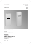
VITODENS 200-W
Type WB2C
Wall mounted gas condensing boiler,
with modulating MatriX cylinder burner for natural gas and LPG
for open or balanced flue operation
5822 432 GB
5/2011
Index
Index
1.
Vitodens 200-W
1.1 Product description .......................................................................................................
4
1.2 Specification .................................................................................................................
6
■ Vitodens 200-W, 45 and 60 kW ................................................................................
7
■ Vitodens 200-W, 80 and 105 kW .............................................................................. 10
2.
Installation accessories
2.1 Product description .......................................................................................................
■ Installation accessories for the Vitodens 200-W, 45 and 60 kW ...............................
■ Installation accessories for the Vitodens 200-W, 80 and 105 kW .............................
■ Installation accessories for multi boiler systems .......................................................
3.
DHW cylinder
3.1 Product description ....................................................................................................... 25
4.
Design information
4.1 Siting, installation ..........................................................................................................
■ Siting conditions for open flue operation (appliance type B) .....................................
■ Siting conditions for balanced flue operation (appliance type C) ..............................
■ Operation of the Vitodens in wet areas .....................................................................
■ Electrical connection .................................................................................................
■ Gas connection .........................................................................................................
■ Minimum clearances .................................................................................................
■ Pre-installation for installing the Vitodens 200-W directly onto a wall (single boiler)
■ Pre-installation, multi boiler system ..........................................................................
4.2 Condensate connection ................................................................................................
■ Condensate drain and neutralisation ........................................................................
4.3 Hydraulic connection ....................................................................................................
■ General information ..................................................................................................
■ Expansion vessels ....................................................................................................
■ Multi boiler systems ..................................................................................................
■ Low loss header ........................................................................................................
25
25
25
26
26
27
27
28
28
34
34
36
36
37
37
37
5.
Control units
5.1 Vitotronic 100, type HC1B, for constant temperature operation ...................................
■ Structure and functions .............................................................................................
■ Specification Vitotronic 100, type HC1B ...................................................................
5.2 Vitotronic 200, type HO1B, for weather-compensated operation .................................
■ Specification Vitotronic 200, type HO1B ...................................................................
5.3 Vitotronic 300-K, type MW2B for multi boiler systems ..................................................
■ Cascade control unit for the Vitodens 200-W with Vitotronic 100 .............................
■ Structure and function ...............................................................................................
■ Specification, Vitotronic 300-K ..................................................................................
■ Delivered condition Vitotronic 300-K .........................................................................
38
38
39
40
41
42
42
42
44
44
2
VIESMANN
5822 432 GB
13
13
23
24
VITODENS 200-W
Index (cont.)
5.4 Vitotronic accessories ...................................................................................................
■ Assignment to control unit types ...............................................................................
■ Vitotrol 100, type UTA ...............................................................................................
■ Vitotrol 100, type UTDB ............................................................................................
■ External extension H4 ...............................................................................................
■ Vitotrol 100, type UTDB-RF ......................................................................................
■ Notes regarding room temperature hook-up (RS function) for remote control units .
■ Information regarding the Vitotrol 200A and 300A ....................................................
■ Vitotrol 200A .............................................................................................................
■ Vitotrol 300A .............................................................................................................
■ Room temperature sensor ........................................................................................
■ Mounting base for programming unit ........................................................................
■ Radio clock receiver ..................................................................................................
■ Vitocom 100, type GSM ............................................................................................
■ Mixer extension kit with integral mixer motor ............................................................
■ Mixer extension kit for separate mixer motor ............................................................
■ Extension kit for one heating circuit with mixer in conjunction with Divicon heating
circuit distributor ........................................................................................................
■ Vitotronic 300-K extension for heating circuits with mixers 2 and 3 ..........................
■ Extension kit for one heating circuit with mixer for the Vitotronic 300-K ...................
■ Immersion thermostat ...............................................................................................
■ Contact thermostat ....................................................................................................
■ Immersion temperature sensor .................................................................................
■ Solar control module, type SM1 ................................................................................
■ Immersion temperature sensor .................................................................................
■ LON communication module .....................................................................................
■ LON connecting cable for data exchange between control units ..............................
■ Extension of the connecting cable ............................................................................
■ Terminator (2 pce) ....................................................................................................
■ KM BUS distributor ...................................................................................................
■ Internal extension H1 ................................................................................................
■ Internal extension H2 ................................................................................................
■ Extension AM1 ..........................................................................................................
■ Extension EA1 ..........................................................................................................
45
45
45
46
46
47
47
47
47
48
49
49
49
50
50
51
51
52
52
52
53
53
53
54
54
55
55
55
55
56
56
56
57
Appendix
6.1 Regulations / Directives ................................................................................................ 57
■ Regulations and Directives ....................................................................................... 57
7.
Keyword index
.............................................................................................................................................. 59
5822 432 GB
6.
VITODENS 200-W
VIESMANN
3
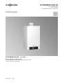
Vitodens 200-W
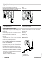
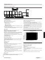
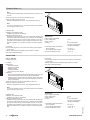
1.1 Product description
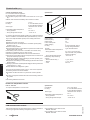
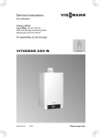
A Inox-Radial heat exchanger made from stainless steel – for high
operational reliability and a long service life. Large heating output
in the smallest of spaces
B Modulating MatriX cylinder burner for extremely clean combustion
and quiet operation
C Variable speed combustion fan for quiet and economical operation
D Gas and water connections
E Digital boiler control unit
1
Vitodens 200-W wall mounted condensing boilers up to 105 kW are
especially suitable for installation in apartment buildings and commercial or public buildings. For these, the Vitodens 200-W offers an affordable, space saving solution – either as a single unit up to 105 kW or
as a cascade with up to eight boilers and a heating output up to 840
kW.
The Inox-Radial heat exchanger made from stainless steel offers high
output in the tightest of spaces. This enables particularly efficient operation with standard seasonal efficiency [to DIN] up to 98 % (Hs) [gross
cv]/109 % (Hi) [net cv].
The Vitotronic 300-K cascade control unit regulates up to four Vitodens
200-W as a single heating centre. In this way, the boiler output is automatically matched to the heat demand. This means that, subject to the
prevailing heat demand, either one boiler modulates or all four boilers
operate concurrently.
For creating cascade systems, we offer perfectly matching system
components, e.g. control units with up to four appliances, fully insulated hydraulic cascades and flue gas headers.
Recommended applications
High heating output from a compact, user friendly wall mounted boiler,
suitable for the following applications:
■ Systems with few, large-demand consumers, e.g. fan heaters in
supermarkets/markets, workshops and industrial premises, nurseries, garages and DHW heating systems
■ Systems with several heating circuits for underfloor and/or static
radiators in apartment buildings, central heating plants for terraced
houses, office buildings and administration premises – particularly
suitable for attic heating centres
■ Heating of public buildings, such as sports centres and multi purpose
halls, schools, kindergartens
■ Suitable for installation in basement boiler rooms, on single floors or
in the attic
■ Durable and efficient through the Inox-Radial heat exchanger
■ Modulating MatriX cylinder burner with a long service life thanks to
stainless steel MatriX mesh – resistant to high temperature loads
■ Easy-to-operate Vitotronic control unit with plain text and graphic
display
■ The programming unit part of the control unit can also be fitted on a
wall mounting base (accessory)
■ Lambda Pro Control combustion controller for all gas types – saving
costs by extending the inspection intervals up to 3 years [in Germany]
■ Quiet operation through low fan speed
Delivered condition
Wall mounted gas condensing boiler with Inox-Radial heat exchanger,
modulating MatriX cylinder burner for natural gas and LPG to DVGW
Code of Practice G260 [Germany], plus wall mounting bracket.
Fully plumbed and wired. White epoxy-coated casing.
Packed separately:
Vitotronic 100 for constant temperature mode
or
Vitotronic 200 for weather-compensated operation.
Preset for operation with natural gas. A conversion within gas groups
E/LL is not required. The conversion to LPG is made at the gas valve
(a conversion kit is not required).
Multi boiler systems
Multi boiler systems for open flue operation with 2, 3 or 4 boilers.
4
VIESMANN
5822 432 GB
Benefits at a glance
■ Option of cascade control with up to eight boilers with a rated heating
output from 45 kW to 840 kW
■ Standard seasonal efficiency [to DIN] up to
98 % (Hs) [gross cv]/109 % (Hi) [net cv]
VITODENS 200-W
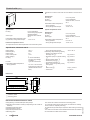
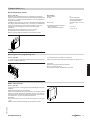
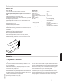
Vitodens 200-W (cont.)
Installation with a self-supporting mounting frame in series and
as a single block
■ Cascade communication module for each boiler
■ Self-supporting mounting frame
Comprising:
■ Hydraulic cascade
■ Connection set for every boiler with:
– Connection lines formed to suit
– Circulation pump (3-stage or high efficiency)
– Ball valves
– Drain & fill valve
– Check valve
– Gas shut-off valve
– Safety valve
■ Thermal insulation
■ Weather-compensated, digital cascade and heating circuit control
unit Vitotronic 300-K
Note
Order circulation pumps for heating circuits and cylinder heating separately.
Tested quality
CE designation according to current EC Directives
5822 432 GB
Meets the requirements for the "Blue Angel" certificate of environmental excellence to RAL UZ 61.
VITODENS 200-W
VIESMANN
5
1
Vitodens 200-W (cont.)
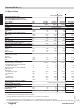
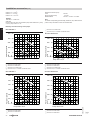
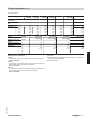
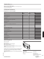
1.2 Specification
Gas boiler, series B and C, category
Rated heating output range
45 and 60 kW: Specification to EN 677.
80 and 105 kW: Specification to EN 15417.
TV/TR = 50/30 °C
TV/TR = 80/60 °C
Rated heat input
Type
Product ID
IP rating
Gas supply pressure
Natural gas
LPG
Max. permissible gas supply pressure*1
Natural gas
LPG
Power consumption (delivered condition)
Weight
Heat exchanger capacity
Max. flow rate
Limit for the use of hydraulic separation
Rated circulation water volume at TV/TR = 80/60 °C
Permiss. operating pressure
Dimensions
Length
Width
Height
Gas connection
Connection values
relative to the max. load
with gas
Natural gas E
Natural gas LL
LPG
Flue gas parameters*2
Flue gas category to G 635/G 636
Temperature (at 30 °C return temperature)
– at rated heating output
– at partial load
Temperature (at 60 °C return temperature)
Mass flow rate
Natural gas
– at rated heating output
– at partial load
LPG
– at rated heating output
– at partial load
Available draught
Standard seasonal efficiency [to DIN] at
TV/TR = 40/30 °C
Average condensate volume
for natural gas and TV/TR = 50/30 °C
Internal diameter of the line to
the expansion vessel
Safety valve
Condensate connection (hose nozzle)
*1
*2
kW
kW
kW
II2N3P
II2N3P
II2N3P
Gas condensing boiler
II2N3P
17.0-45.0
15.4-40.7
16.1-42.2
WB2C
17.0-60.0
30.0-80.0
15.4-54.4
27.0-72.6
16.1-56.2
28.1-75.0
WB2C
WB2C
CE-0085BR0432
IP X4D to EN 60529
30.0-105.0
27.0-95.6
28.1-98.5
WB2C
mbar
mbar
20
50
20
50
20
50
20
50
mbar
mbar
W
kg
l
l/h
25.0
57.5
56
65
7.0
3500
25.0
57.5
82
65
7.0
3500
25.0
57.5
90
83
12.8
5700
25.0
57.5
175
83
12.8
5700
l/h
bar
1748
4
2336
4
3118
4
4106
4
mm
mm
mm
R
380
480
850
¾
380
480
850
¾
530
480
850
1
530
480
850
1
m3/h
m3/h
kg/h
4.47
5.19
3.30
5.95
6.91
4.39
7.94
9.23
5.88
10.42
12.12
7.74
G52/G51
G52/G51
G52/G51
G52/G51
35
33
65
40
35
70
35
33
65
40
35
70
kg/h
kg/h
81.2
31.1
110.6
31.1
147.5
55.8
193.3
55.8
kg/h
kg/h
Pa
mbar
78.2
26.6
250
2.5
106.7
26.6
250
2.5
143.8
46.4
250
2.5
185.4
46.4
250
2.5
°C
°C
°C
%
up to 98 (Hs) [gross cv]/109 (Hi) [net cv]
l/day
14-19
23-28
25-30
35-40
DN
DN
Ø mm
22
22
20-24
22
22
20-24
28
22
20-24
28
22
20-24
If the gas supply pressure is higher than the maximum permitted value, install a separate gas pressure governor upstream of the system.
Calculation values for sizing the flue system to EN 13384.
Flue gas temperatures measured as gross values at 20 °C combustion air temperature.
The flue gas temperature at a return temperature of 30 °C is significant for the sizing of the flue system.
The flue gas temperature at a return temperature of 60 °C is used to determine the application range of flue pipes with maximum permissible
operating temperatures.
6
VIESMANN
VITODENS 200-W
5822 432 GB
1
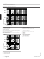
Vitodens 200-W (cont.)
Gas boiler, series B and C, category
II2N3P
Rated heating output range
45 and 60 kW: Specification to EN 677.
80 and 105 kW: Specification to EN 15417.
TV/TR = 50/30 °C
TV/TR = 80/60 °C
Flue gas connection
Ventilation air connection
II2N3P
II2N3P
Gas condensing boiler
II2N3P
1
kW
kW
Ø mm
Ø mm
17.0-45.0
15.4-40.7
80
125
17.0-60.0
15.4-54.4
80
125
30.0-80.0
27.0-72.6
100
150
30.0-105.0
27.0-95.6
100
150
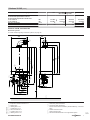
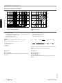
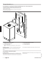
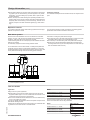
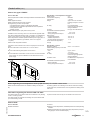
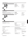
Vitodens 200-W, 45 and 60 kW
Multi boiler systems
For further details regarding multi boiler systems, see page 28.
480
160
40
1975 N
200
E
K
80
B C
D F G 176
982
902
1700 O
1166 M
H
A
850
752
875 L
P
B
R
100
380
240
305
400
5822 432 GB
S
A
B
C
D
E
F
G
Expansion vessel connection G 1
Safety valve
Heating flow G 1½
Cylinder flow G 1½
Gas connection R ¾
Cylinder return G 1½
Heating return G 1½
VITODENS 200-W
H Cable entry area at the back
K Connection sets (accessory)
Shown without thermal insulation (standard delivery, connection
sets)
L Without connection sets
M With connection sets
N Recommended dimension for a single boiler system
VIESMANN
7
Vitodens 200-W (cont.)
O Recommended dimension for a multi boiler system
P Balanced flue connection with bend (accessory)
Note
Lay all required supply cables on site and route them into the boiler
near H.
Variable speed high efficiency circulation pump in the heating circuit connection set (accessory)
This circulation pump is a highly efficient pump with more than 50 %
Variable speed (Δp constant or Δp variable), fully wired.
lower power consumption than conventional pumps.
Matching the pump rate of the circulation pump to the individual system
Note
conditions reduces the power consumption of the heating system.
When operating in multi boiler systems, select speed control Δp constant.
Circulation pump VI Para 25/1-7
Rated voltage
V~
230
Power consumption
W
max.
70
min.
5
Residual head of the circulation pump
60
600
50
500
40
400
30
300
20
10
0
Residual head in mbar
.
ax
700
M
70
kPa
200
100
0
0
Flow rate in l/h
1000
2000
3000
3-speed heating circuit pump in the heating circuit connection set (accessory)
Circulation pump VIRS 25/7-3
Rated voltage
V~
Rated current
A
max.
min.
Capacitor
µF
Power consumption
W
Stage 1
Stage 2
Stage 3
230
0.58
0.30
3.5
62
92
132
3-stage, fully wired ready, to plug in.
5822 432 GB
1
R Condensate drain
S Top edge finished floor
8
VIESMANN
VITODENS 200-W
Vitodens 200-W (cont.)
Residual head of the circulation pump
70
700
60
600
50
500
40
400
1
300
Residual head in mbar
30
kPa
C
B
A
20
200
10
100
0
0
0 200 400 600 800 1000 1200 1400 1600 1800 2000 2200 2400 2600
Flow rate in l/h
A Stage 1
B Stage 2
C Stage 3
Pressure drop on the heating water side
For sizing an on-site circulation pump
600
50
500
40
30
20
kPa
10
0
Pressure drop in mbar
60
400
300
200
100
0
0
500
1000
Flow rate in l/h
1500
2000
2500
3000
3500
Circulation pump in the connection set for DHW cylinders
V~
W
max.
min.
VI RS 25/6-3
230
93
46
5822 432 GB
Pump type
Voltage
Power consumption
VITODENS 200-W
VIESMANN
9
Vitodens 200-W (cont.)
Residual head of the circulation pump
60
600
50
500
40
400
30
300
20
kPa
10
0
Head in mbar
1
A
200
B
C
100
0
0
0,5
1
Pump rate in m³/h
1,5
2
2,5
3
3,5
A Stage 1
B Stage 2
C Stage 3
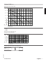
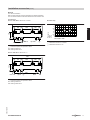
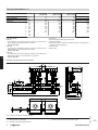
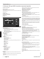
Vitodens 200-W, 80 and 105 kW
Multi boiler systems
For further details regarding multi boiler systems, see page 28.
480
K
40
1975 N
O
200
E
1700
1300 M
850
752
875 L
236
P
A
H
B
160
F
C
A
B
C
D
E
10
100
160
G
Safety valve
Expansion vessel connection G1
Boiler flow 7 42 mm
Cylinder flow 7 35 mm
Gas connection R 1
VIESMANN
530
F Cylinder return 7 35 mm
G Boiler return 7 42 mm
H Connection sets (accessory)
Shown without thermal insulation (standard delivery, connection
sets)
VITODENS 200-W
5822 432 GB
D
Vitodens 200-W (cont.)
K Cable entry area at the back
L Without connection set (accessories)
M With connection set (accessories)
N Recommended dimension (single boiler system)
O Recommended dimension (multi boiler system)
P Condensate drain
Note
The heating circuit connection set must be ordered separately.
Note
Lay all required supply cables on site and route them into the boiler
near K.
Variable speed high efficiency circulation pump in the heating circuit connection set (accessory)
This circulation pump is a highly efficient pump with more than 50 %
Circulation pump VI Para 25/1-11
lower power consumption than conventional pumps.
Rated voltage
V~
Matching the pump rate of the circulation pump to the individual system
Power consumption
W
max.
conditions reduces the power consumption of the heating system.
min.
230
140
7
Variable speed (Δp constant or Δp variable), fully wired.
Note
When operating in multi boiler systems, select speed control Δp constant.
Residual head of the circulation pump
100
90
800
70
700
60
600
40
30
20
10
0
Residual head in mbar
80
50
kPa
1000
900
Ma
500
x.
400
300
200
100
0
0
1000
Flow rate in l/h
2000
3000
4000
3-speed heating circuit pump in the heating circuit connection set (accessory)
Circulation pump VI UPS 25-100
Rated voltage
V~
Power consumption
W
Stage 1
Stage 2
Stage 3
230
280
340
345
5822 432 GB
3-stage, fully wired ready, to plug in.
VITODENS 200-W
VIESMANN
11
1
Vitodens 200-W (cont.)
Residual head of the circulation pump
1200
110
1100
100
90
1000
900
80
800
70
700
60
600
50
40
30
kPa
20
10
0
Residual head in mbar
120
500
400
300
200
100
0
A
0
1000
Flow rate in l/h
2000
3000
4000
C
B
5000
6000
A Stage 1
B Stage 2
C Stage 3
Note
Observe further details regarding the use of a low loss header (see
page 37).
If the residual head of the circulation pumps (available as accessories)
is insufficient to overcome the following system pressure drop values,
install an additional, external circulation pump on site.
In such cases, use a low loss header.
Pressure drop on the heating water side
For sizing a circulation pump on site (when connecting to DHW cylinder
connection set)
600
50
500
30
20
10
400
300
200
100
0
0
1000
2000
Flow rate in l/h
3000
4000
5000
6000
7000
5822 432 GB
0
Pressure drop in mbar
60
40
kPa
1
12
VIESMANN
VITODENS 200-W
Installation accessories
2.1 Product description
Installation accessories for the Vitodens 200-W, 45 and 60 kW
Heating circuit connection set without circulation pump
Part no. 7245 738
Connections G 1½
Comprising:
■ Tee with ball valve
■ Boiler drain & fill valve
■ Safety valve
■ Gas shut-off valve with integral thermally activated safety shut-off
valve
■ Connection G1 for expansion vessel
■ Circulation pump
■ 2 tees with ball valve
■ Non-return valve
■ 2 boiler drain & fill valves
■ Safety valve
■ Gas shut-off valve with integral thermally activated safety shut-off
valve
■ Thermal insulation
■ Connection G1 for expansion vessel
Heating circuit connection set with variable speed high efficiency
circulation pump
Part no. 7424 757
Connections G 1½
Comprising:
■ Circulation pump
■ 2 tees with ball valve
■ Non-return valve
■ 2 boiler drain & fill valves
■ Safety valve
■ Gas shut-off valve with integral thermally activated safety shut-off
valve
■ Thermal insulation
■ Connection G1 for expansion vessel
Connection set for DHW cylinders
Part no. Z006 183
Connections G 1½
Comprising:
■ Circulation pump
■ 2 ball shut-off valves
■ Non-return valve
■ Cylinder temperature sensor
5822 432 GB
Heating circuit connection set with 3-stage circulation pump
Part no. 7247 341
Connections G 1½
Comprising:
VITODENS 200-W
Ball valve
Part no. 7247 373
1 pce G 1¼ with gasket and union nut.
VIESMANN
13
2
Installation accessories (cont.)
Divicon heating circuit distributor
■ The bypass valve for hydraulic balancing of the heating system is
available as an accessory as a threaded component for inserting into
the prepared hole in the cast body.
■ The overflow valve may be required when using staged pumps to
prevent the heating system running noisily. It is mounted onto the
Divicon.
■ Individually wall mounted or with a double or triple manifold.
■ Also available as kit. For further details, see the Viessmann pricelist.
For part no. in conjunction with the different circulation pumps, see Viessmann pricelist.
The dimensions of the heating circuit distributor are the same, with or without mixer.
HV
120
HR
151
a
98
A
b
Heating circuit connection
Flow rate (max.)
a (female)
a (male)
b (female)
b (male)
R
m3/h
Rp
G
Rp
G
¾
1
1¼
1.0
¾
1¼
¾
1¼
1.5
1
1½
1
1¼
2.5
1¼
2
1¼
2
B
C
398
D
E
G 1½
HV
HR
Divicon with mixer (wall mounting without thermal insulation and without mixer drive extension kit)
HR
HV
A
B
C
D
E
Heating return
Heating flow
Overflow valve (accessory for multi stage circulation pump)
Ball valves with thermometer (as programming unit)
Circulation pump
Bypass valve (accessory)
Mixer-3
5822 432 GB
2
Construction and function
■ Available with R ¾ , R 1 and R 1¼ connections.
■ With heating circuit pump, check valve, ball valves with integral thermometers and 3-way mixer or without mixer.
■ Quick and simple installation through pre-assembled unit and compact design.
■ Low radiation losses through all-round thermal insulation shells.
■ Low electricity costs and precise control characteristics through the
use of high efficiency pumps and optimised mixer curve.
■ Also available with staged pumps.
14
VIESMANN
VITODENS 200-W
Installation accessories (cont.)
HV
HR
Heating circuit connection
Flow rate (max.)
a (female)
a (male)
b (female)
b (male)
142
a
98
A
120
b
R
m3/h
Rp
G
Rp
G
¾
1
1¼
1.0
¾
1¼
¾
1¼
1.5
1
1½
1
1¼
2.5
1¼
2
1¼
2
B
C
398
2
D
HV
HR
G 1½
Divicon without mixer (wall mounting, shown without thermal insulation)
HR
HV
A
B
C
D
Heating return
Heating flow
Overflow valve (accessory for multi stage circulation pump)
Ball valves with thermometer (as programming unit)
Circulation pump
Ball valve
Installation example: Divicon with triple manifold
120
120
180
Dimensions
120
a
b
c
d
HR
Manifold with heating circuit connection
R ¾ and R 1
R 1¼
135
183
535
583
784
784
G 1¼
G2
a
b
HV
180
d
HV
c
HR
5822 432 GB
(shown without thermal insulation)
HR Heating return
HV Heating flow
VITODENS 200-W
VIESMANN
15
Installation accessories (cont.)
Determining the required internal diameter
5.0
5.0
A
Flow rate in m³/h
1.0
0.5
0.2
B
0.5
0.2
C
0.1
D
1
Mixer control characteristics
A Divicon with mixer-3
The identified operating ranges B to D provide optimum control
characteristics with the Divicon mixer:
B Divicon with mixer-3 (R ¾)
Application range: 0 to 1.0 m 3/h
Example:
Heating circuit for radiators with an output of ² = 11.6 kW
Heating system temperature 75/60 °C (ΔT = 15 K)
c
µ
²
´
1.0
Specific heat capacity
Mass flow rate
Output
Flow rate
3
5
10
0.1
20 30 40
Heating circuit output
in kW
C Divicon with mixer-3 (R 1)
Application range: 0 to 1.5 m 3/h
D Divicon with mixer-3 (R 1¼)
Application range: 0 to 2.5 m 3/h
Wh
² = µ · c · ΔT
c = 1.163
²
11600 W · kg · K
´=
c · ΔT
=
kg · K
1.163 Wh · (75-60) K
´ (1 kg ≈ 1 dm³)
µ
= 665
kg
h
0.665
m³
h
Select the smallest possible mixer within the application range with
value ´.
Result of this example: Divicon with mixer-3 (R ¾)
Bypass valve
Overflow valve
Part no. 7464 889
To hydraulically balance the heating circuit with mixer. Inserted into
the Divicon.
Part no. 7429 738: R ¾
Part no. 7429 739: R 1
Part no. 7429 740: R 1¼
Only with manually controlled heating circuit pump. Fitted onto the
Divicon.
5822 432 GB
2
2.5
2.0
1.5
ΔT
=
ΔT
5K
ΔT =
1
=
0
Δ
15 K
ΔT T=
K
= 20K
30
K
2.5
2.0
1.5
16
VIESMANN
VITODENS 200-W
Installation accessories (cont.)
Manifold
Incl. thermal insulation
Wall mounted with wall mounting bracket to be ordered separately.
The connection between boiler and manifold must be made on site.
For 2 Divicon
Part no. 7460 638 for Divicon R ¾ and R 1
Pressure drop
495
120
HR
180
HV 120
HR
135
Pressure
drop
kPa
HV
120
HV
G 1½
HR
Rp ¾
3.5
3
2.5
2
A
B
1.5
1
0.5
0
0
0.5
1
1.5
2
Flow rate in m³/h
2
2.5
A
A Manifold for Divicon R ¾ and R 1
B Manifold for Divicon R 1¼
A Connection option for expansion vessel
HV Heating water flow
HR Heating water return
Part no. 7466 337 for Divicon R 1¼
495
120
HR
180
HV 120
HR
183
HV
420
G 2 HV
Rp ¾
A
G2
HR
5822 432 GB
A Connection option for expansion vessel
HV Heating water flow
HR Heating water return
VITODENS 200-W
VIESMANN
17
Installation accessories (cont.)
For 3 Divicon
Part no. 7460 643 for Divicon R ¾ and R 1
120
HR
180
HV
784
HR
120
180
HV
120
HR
135
HV
Pressure drop
120
G 1½
HV
A
Rp ¾
Pressure
drop
kPa
2
HR
A Connection option for expansion vessel
HV Heating water flow
HR Heating water return
180
HV
1.5
2
2.5
784
HR
120
180
HV
120
HR
183
120
HR
B
A Manifold for Divicon R ¾ and R 1
B Manifold for Divicon R 1¼
Part no. 7466 340 for Divicon R 1¼
HV
5.5
5
4.5
4
3.5
3
A
2.5
2
1.5
1
0.5
0
0
0.5
1
Flow rate in m³/h
420
HV
A
G 2 HR
G2
Rp ¾
A Connection option for expansion vessel
HV Heating water flow
HR Heating water return
Wall mounting bracket
Part no. 7465 894
for individual Divicon
With screws and dowels.
Part no. 7465 439
for manifold
With screws and dowels.
a
a
for Divicon
a
mm
with mixer
151
without mixer
142
mm
R ¾ and R 1
142
R 1¼
167
5822 432 GB
for Divicon
a
18
VIESMANN
VITODENS 200-W
Installation accessories (cont.)
Low loss header
Part no. 7460 649
Flow rate max. 4.5 m3/h
Including thermal insulation and integral sensor well.
The connection between boiler and low loss header must be made on
site.
Pressure drop
447
120
14
12
10
8
6
4
2
0
HR
275
Pressure
drop
kPa
HV
2
0
1
2
3
Flow rate in m³/h
4
5
4
5
A
G 1½
B
350
Rp 1
HV
A
B
HV
HR
HR
Sensor well
Optional blow-down
Heating water flow
Heating water return
Part no. 7460 648
Flow rate max. 7.5 m3/h
Including thermal insulation and integral sensor well.
The connection between boiler and low loss header must be made on
site.
Pressure drop
523
HV
HR
420
295
Pressure
drop
kPa
G2
A
G2
HV
5822 432 GB
16
14
12
10
8
6
4
2
0
B
420
0
1
2
3
Flow rate in m³/h
6
7
8
Rp 2
HR
Circulation pump curves and pressure drop on the heating water side
The residual pump head results from the difference between the selecThe following pump diagrams show the pressure drop curves of the
ted pump curve and the pressure drop curve of the respective heating
different Dicivon heating circuit distributors.
circuit distributor or further components (pipe assembly, distributor
etc.).
Maximum flow rate for Divicon:
VITODENS 200-W
VIESMANN
19
Installation accessories (cont.)
■ with R ¾ = 1.0 m3/h
■ with R 1 = 1.5 m3/h
■ with R 1¼ = 2.5 m3/h
Head of the relevant pump
curve:
Divicon pressure drop:
Residual head:
Example:
Flow rate ´ = 0.665 m3/h
Selected:
Divicon with mixer R ¾ and circulation pump Wilo VIRS 25/4-3, pump
curve 2, pump rate 0.7 m 3/h
28 kPa
3.5 kPa
28 kPa – 3.5 kPa = 24.5 kPa.
Note
For further components (pipe assembly, distributor, etc.) determine the
pressure drop and deduct it from the residual head.
Manually controlled heating circuit pumps
C Divicon R 1¼ with mixer
D Divicon R ¾, R 1 and R 1¼ without mixer
Wilo VIRS 25/4-3
he
ad
3
2
100
10
kPa
0
0
C
1.5
2.0
A
B
C
D
Wilo VIRS 25/6-3
50
400
40
300
30
He
ad
0
C
B
A
0
0.5
1.0
Pump rate in m³/h
D
1.5
2.0
2.5
Divicon R ¾ with mixer
Divicon R 1 with mixer
Divicon R 1¼ with mixer
Divicon R ¾, R 1 and R 1¼ without mixer
Ma
x. h
ea
d
400 40
300 30
200 20
10
0
ad
min
.
500 50
2
A
C
B
0
0.5
1.0
Pump rate in m³/h
VIESMANN
1.5
2.0
Mi
n.
he
ad
100 10
D
A Divicon R ¾ with mixer
B Divicon R 1 with mixer
20
ma
x.3
20
kPa
100
x.
He
10
0
ma
600 60
1
in.
200
0
ad
Grundfos VIUPS 25-60
m
ad
500
20
He
He
60
30
2.5
Divicon R ¾ with mixer
Divicon R 1 with mixer
Divicon R 1¼ with mixer
Divicon R ¾, R 1 and R 1¼ without mixer
600
300
100
D
0
0.5
1.0
Pump rate in m³/h
40
200
B
A
400
2.5
0
0
A
C
B
D
0
0.5
1.0
Pump rate in m³/h
1.5
2.0
2.5
5822 432 GB
20
.1
200
in
A
B
C
D
30
x.
m
Pressure drop/head
mbar
300
Ma
kPa
40
kPa
400
Grundfos VIUPS 25-40
Pressure drop/head
mbar
50
Pressure drop/head
mbar
500
Pressure drop/head
mbar
2
A Divicon R ¾ with mixer
B Divicon R 1 with mixer
VITODENS 200-W
Installation accessories (cont.)
C Divicon R 1¼ with mixer
D Divicon R ¾, R 1 and R 1¼ without mixer
Heating circuit pumps regulated by differential pressure
According to the [German] Energy Savings Order (EnEV), circulation
pumps in central heating systems must be sized in accordance with
current technical rules. Circulation pumps in central heating systems
with rated output higher than 25 kW should be equipped and designed
in such a way that the power consumption will be automatically
matched to the operational (capacity) requirements in at least 3 stages,
if no safety concerns relating to the boiler make demands to the contrary.
In addition to the EnEV regulations, the use of regulated pumps is also
recommended for smaller capacities.
Design information
The use of differential pressure regulated heating circuit pumps
requires heating circuits with variable flow rate, e.g. single line and
twin-line systems with thermostatic valves, underfloor heating with
thermostatic or zone valves.
2
Wilo Stratos Para 25/1-7
■ Very economical HE pump (in accordance with Energy Label A)
Operating mode: Constant differential pressure
700 70
600 60
C
Δp
500 50
400 40
ax
m
Pressure drop/head
mbar
.
300 30
200 20
100 10
kPa
A
0
B
0
0
0.5
1.0
Pump rate in m³/h
D
1.5
2.0
2.5
3.0
3.5
4.0
C Divicon R 1¼ with mixer
D Divicon R ¾, R 1 and R 1¼ without mixer
5822 432 GB
A Divicon R ¾ with mixer
B Divicon R 1 with mixer
C
VITODENS 200-W
VIESMANN
21
Installation accessories (cont.)
Operating mode: Variable differential pressure
700 70
600 60
-V
Δp
500 50
2
400 40
.
ax
m
Pressure drop/head
mbar
300 30
200 20
100 10
C
B
kPa
A
0
0
0
0.5
1.0
Pump rate in m³/h
D
1.5
2.0
2.5
A Divicon R ¾ with mixer
B Divicon R 1 with mixer
3.0
3.5
4.0
C Divicon R 1¼ with mixer
D Divicon R ¾, R 1 and R 1¼ without mixer
Grundfos Alpha 2-60
■ Very economical HE pump (in accordance with Energy Label A)
■ with power consumption indication
■ with Autoadapt function (automatic matching to the pipework)
■ with night setback function
600 60
500 50
C
D
E
F
G
H
K
L
M
Divicon R 1¼ with mixer
Divicon R ¾, R 1 and R 1¼ without mixer
Stage 1
Stage 2
Stage 3
Min. proportional pressure
Max. proportional pressure
Min. constant pressure
Max. constant pressure
M
400 40
G
300 30 L
Pressure drop/head
mbar
F
200 20 K
100 10
H
E
C
B
kPa
A
0
0
0
0.5
1.0
Pump rate in m³/h
D
1.5
2.0
2.5
22
VIESMANN
5822 432 GB
A Divicon R ¾ with mixer
B Divicon R 1 with mixer
VITODENS 200-W
Installation accessories (cont.)
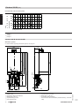
Installation accessories for the Vitodens 200-W, 80 and 105 kW
Heating circuit connection set with variable speed high efficiency
circulation pump
Part no. 7424 759
Comprising:
■ Circulation pump
■ 2 ball valves with adaptors Ø 42 mm (locking ring fitting)
■ Tee with ball valve
■ Non-return valve
■ Boiler drain & fill valve
■ Safety valve
■ Gas shut-off valve with integral thermally activated safety shut-off
valve
■ Thermal insulation
■ Connection G1 for expansion vessel
2
Low loss header
For flow rate up to 8 m3/h
Part no. Z007 743
Comprising:
■ Low loss header with integral sensor well (50 mm long)
■ Thermal insulation
■ Immersion temperature sensor for the low loss header
■ Quick-action air vent valve
■ 2 adaptors Ø 42 mm (locking ring fitting)
364
313
413
963
Part no. 7424 951
Comprising:
■ Circulation pump
■ 2 ball valves with adaptors Ø 42 mm (locking ring fitting)
■ Tee with ball valve
■ Non-return valve
■ Boiler drain & fill valve
■ Safety valve
■ Gas shut-off valve with integral thermally activated safety shut-off
valve
■ Thermal insulation
■ Connection G1 for expansion vessel
863
1078
Heating circuit connection set with 3-stage circulation pump
204 160
Mounting panel for low loss header
■ For floor mounting
Part no. 7346 787
■ For wall mounting
Part no. 7346 788
Connection set for DHW cylinders
5822 432 GB
Part no. 7348 934
Connections: Ø 35 mm (locking ring fitting)
Comprising:
■ Connecting lines for flow and return
■ Cylinder temperature sensor
VITODENS 200-W
VIESMANN
23
Installation accessories (cont.)
2
Installation accessories for multi boiler systems
Hydraulic cascades
See page 28.
Flue gas cascade (positive pressure)
Comprising:
■ Flue gas non-return device for each boiler
■ Flue gas header
■ End piece with condensate drain and siphon
A
C
B
B
B
B
■ 4-boiler system installed in series
– For the Vitodens 200-W, 30 to 105 kW: Part no. 7311 998
■ 6-boiler system installed in series
– For the Vitodens 200-W, 30 to 105 kW: Part no. 7452 576
■ 8-boiler system installed in series
– For the Vitodens 200-W, 30 to 105 kW: Part no. 7452 577
■ 4-boiler system installed as single block
– For the Vitodens 200-W, 17 to 45 kW: Part no. 7454 138
– For the Vitodens 200-W, 17 to 60 kW: Part no. 7454 138
– For the Vitodens 200-W, 30 to 80 kW: Part no. 7454 139
– For the Vitodens 200-W, 30 to 105 kW: Part no. 7454 139
■ 6-boiler system installed as single block
– For the Vitodens 200-W, 30 to 105 kW: Part no. 7452 578
■ 8-boiler system installed as single block
– For the Vitodens 200-W, 30 to 105 kW: Part no. 7452 579
For further technical details regarding the flue gas cascades, see the
technical guide to Vitodens flue systems.
A Flue gas header
B Flue gas non-return device
C End piece with siphon
5822 432 GB
■ 2-boiler system installed in series
– For the Vitodens 200-W, 17 to 45 kW: Part no. 7247 262
– For the Vitodens 200-W, 17 to 60 kW: Part no. 7247 262
– For the Vitodens 200-W, 30 to 80 kW: Part no. 7311 995
– For the Vitodens 200-W, 30 to 105 kW: Part no. 7311 995
■ 3-boiler system installed in series
– For the Vitodens 200-W, 17 to 45 kW: Part no. 7247 263
– For the Vitodens 200-W, 17 to 60 kW: Part no. 7247 264
– For the Vitodens 200-W, 30 to 80 kW: Part no. 7311 996
– For the Vitodens 200-W, 30 to 105 kW: Part no. 7311 997
24
VIESMANN
VITODENS 200-W
DHW cylinder
3.1 Product description
For details regarding DHW cylinders, see the technical guide to the
Vitodens up to 35 kW, or separate datasheets.
Design information
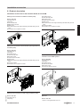
4.1 Siting, installation
Siting conditions for open flue operation (appliance type B)
(Type B23 and B33)
In rooms where air contamination through halogenated hydrocarbons can occur, such as hairdressing salons, printing shops, chemical
cleaners, laboratories, etc., install the Vitodens only as a balanced flue
system.
If in doubt, please contact us.
Wall mounted boilers should not be installed in areas subject to very
dusty conditions.
A ventilation air filter is available as an accessory for operation during
the building phase. This protects the appliance against excessive dust
loads.
The installation location must be kept free from frost and must be adequately ventilated.
Provide a condensate drain and a discharge pipe for the safety valve
in the installation room.
The maximum ambient temperature of the system should not exceed
35 ºC.
If these instructions are not observed, any consequential loss directly
related to any of these causes is excluded from our warranty.
For further details, see the technical guide on flue systems for the
Vitodens.
Installation room (up to 50 kW)
Permissible:
■ Boiler installation on the same floor
■ Adjacent rooms with interconnected room air supply (larders, basements, utility rooms, etc.)
■ Attic rooms, but only with adequate minimum chimney height to DIN
18160 – 4 m above inlet (negative pressure operation).
Not permissible:
■ Stairwells and common hallways; exception: Detached and twofamily homes of low height (top edge of floor in the top storey <
7 m above ground level)
■ Bathrooms and toilets without outside windows, with duct ventilation
■ Rooms where explosive or flammable materials are stored
■ Rooms ventilated mechanically or via individual duct systems to DIN
18117-1.
Observe all local fire regulations.
Vitodens 200-W from 60 kW and multi boiler systems
Install boilers from 50 kW in accordance with the Combustion Order
(FeuVo) [Germany] [or local regulations] in a separate installation
room. Fit the mains isolator outside the installation room.
Combustion air apertures
Gas equipment with a total rated heating output in excess of 50 kW
must be provided with combustion air apertures leading to the outside.
The cross-section should be at least 150 cm2 and should be 2 cm2
larger for each kW above 50 kW rated heating output. This cross-section may not be split over more than 2 apertures (observe FeuVo and
TRGI 2008 point 5.5.4 [or local regulations]).
Example:
Vitodens 200-W, 3 × 60 kW
Total rated heating output 180 kW
150 cm2 + 130 × 2 cm2 = 410 cm2 or 2 × 205 cm2.
The combustion air vents should be at least 410 cm2 or 2 × 205 cm2.
Connection on the flue gas side
(for further details, see the technical guide "Flue systems for the
Vitodens")
The connection piece to the chimney should be as short as possible.
Therefore position the Vitodens as close to the chimney as possible.
No special protective measures or clearances towards combustible
objects, e.g. furniture, cartons or similar, need to be taken/observed.
The surface temperatures of the Vitodens and the flue system do not
exceed 85 ºC at any point.
Extractors
When installing appliances with extraction to the outside (cooker
hoods, extractor fans etc.), ensure that air extraction will not create
negative pressure inside the installation room. A return flow of flue gas
could result if the ventilation system and the Vitodens were operated
simultaneously. In such cases, install an interlock circuit.
For this, internal extension H2 (accessory) can be used. This switches
the extractors off when the burner is started.
Multi boiler systems with pressurised flue systems
The Vitodens 200-W multi boiler systems with common pressurised
flue systems are designed for open flue operation (type B).
Siting conditions for balanced flue operation (appliance type C)
5822 432 GB
The Vitodens can be installed as appliance type C13x, C33x, C43x, C53x,
C63x or C83x to TRGl 2008, for balanced flue operation, independent
of the size and ventilation of the installation room.
VITODENS 200-W
It may, for example, be sited in recreation rooms, in other living spaces,
in ancillary rooms without ventilation, in cupboards (open at the top)
or recesses, without maintaining minimum clearances to combustible
parts, or in attic rooms (pitched attics and the long pane of the roof)
where the balanced flue pipe can be directly routed through the roof.
Since the flue pipe connection for balanced flue operation is surrounded by combustion air (coaxial pipe), no clearances towards combustible parts need to be maintained (for further details, see the technical
guide "Flue systems for the Vitodens").
The installation room must be free from the risk of frost.
Provide a condensate drain and a discharge pipe for the safety valve
in the installation room.
VIESMANN
25
3
Design information (cont.)
Electrical interlocks for extractors (extractor hoods, etc.) are not
required with balanced flue operation.
Vitodens 200-W from 60 kW
Install boilers from 50 kW in a separate room in accordance with the
Combustion Order (FeuVo) [Germany] [or local regulations]. Fit the
mains isolator outside the installation room.
Appropriate ventilation air and extract air apertures are required in
accordance with TRGI (see the technical guide on flue systems for the
Vitodens).
Installation in a garage
Tests carried out by the Gaswärme-Institut e.V., Essen, have confirmed that the Vitodens is suitable for installation in garages.
When installing this boiler in garages, maintain a clearance between
the floor and the burner of at least 500 mm. Protect the boiler on site
with a bracket or deflector against mechanical damage.
Operation of the Vitodens in wet areas
The Vitodens is approved for installation in wet areas (IP rating:
IP X4 D, splashproof)
When installing the Vitodens in wet areas, observe the safety zones
and minimum wall clearances according to VDE 0100 [or local regulations]. The Vitodens 200-W may be installed in safety zone 1.
Electrical connection
752
A
B
200
40
A Reference point Vitodens top edge
B Area for power supply cables
Recommended leads/cables
NYM 3 G 1.5 mm2
2-core min. 0.75 mm2
– Power cables (also for accessories)
– DHW circulation pump
–
–
–
–
–
–
–
–
–
Extension AM1 or EA1
Outside temperature sensor
Vitotronic 200-H (LON)
Extension kit for heating circuit with mixer
(KM BUS)
Vitotrol 100, type UTDB (230 V)
Vitotrol 200A
Vitotrol 300A
Vitohome 300
Radio clock receiver
Interlock switch
Install an interlock for open flue operation if an extractor (e.g. cooker
hood) is fitted in the room providing interconnected combustion air
supply.
For this, the internal extension H2 (accessories) can be used. This
switches the extractors OFF when the burner is started.
26
VIESMANN
4-core 1.5 mm2
or
3-core 1.5 mm2 without green/yellow
core
– Vitotrol 100, type UTDB-RF (230 V)
– Vitotrol 100, type UTA
Power supply for accessories
The power supply for accessories can be connected directly to the
control unit.
This connection is switched by the system ON/OFF switch.
If the total system current exceeds 6 A, connect one or more extensions via an ON/OFF switch directly to the mains supply.
Where the boiler is installed in a wet area, the power supply connection
of accessories must not be made at the control unit.
VITODENS 200-W
5822 432 GB
4
The power supply must comply with the requirements of your local
power supply utility and current VDE [or local] regulations.
Protect the power cable with a fuse with a max. rating of 16 A.
We recommend installing an AC/DC-sensitive RCD (RCD class B) for
DC (fault) currents that can occur with energy efficient equipment.
Make the power supply (230 V~, 50 Hz) via a permanent connection.
Connect the supply cables and accessories at the terminals inside the
boiler.
Allow cables/leads in the shaded area to protrude at least 800 mm from
the wall (see diagram):
Design information (cont.)
Additional requirements when installing boilers with LPG operation in rooms below ground level
According to TRF 1996 Vol. 2 – valid as of 1 September 1997 – an
external safety solenoid valve is no longer required when installing the
Vitodens below ground level.
However, the high safety standard derived from the use of an external
safety solenoid valve has proven valuable. We therefore recommend
the installation of an external safety solenoid valve when installing the
boiler in rooms below ground level. This requires the internal extension
H1.
Gas connection
Gas installations must only be carried out by a registered gas fitter.
Connect and size the mains gas according to TRGI 2008 or TRF 1996
[or local regulations].
Max. test pressure 150 mbar.
We recommend the installation of a gas filter compliant with DIN 3386
in the gas line.
Thermally activated safety shut-off valve
According to paragraph 4, section 5 of the FeuVo 2008 [or local regulations], thermally activated shut-off equipment must be installed in
gas combustion equipment or in gas lines immediately upstream of the
gas combustion equipment, which will shut off the gas supply if the
external temperature exceeds 100 ºC. These valves must isolate the
gas supply for at least 30 minutes up to a temperature of 650 ºC. This
should prevent the formation of explosive gas mixtures in the event of
a fire.
The gas taps supplied with the Vitodens are equipped with integral
thermally activated safety shut-off valves.
Sizing recommendation, gas flow limiter
In supply areas with HIB below 8.6 kWh/m3 and gas appliances compliant with category I2N, determine a fictitious rated heat input. This
fictitious rated heat input results from the rated heat input (QNB) of the
appliance, multiplied by a factor of 1.23 (ratio HIB 8.6/7.0). Select the
gas flow limiter and size the pipework in accordance with the TRGI
2008 [or local regulations] using this fictitious rated heat input.
Rated heating output range of the
Vitodens
kW
17.0-45.0
17.0-60.0
30.0-80.0
30.0-105.0
Gas flow limiter
GS 10
GS 16
GS 16
GS 16
The selection recommendation for the gas flow limiter does not waive
the requirement for sizing the pipework correctly.
Minimum clearances
4
Maintenance clearances to the l.h. or r.h. side of the Vitodens are
not required.
5822 432 GB
Maintain a clearance of 700 mm in front of the Vitodens or the DHW
cylinder for maintenance purposes.
VITODENS 200-W
VIESMANN
27
Design information (cont.)
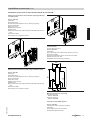
Pre-installation for installing the Vitodens 200-W directly onto a wall (single boiler)
An installation template is supplied with the Vitodens 200-W for the
location of fixing holes for the wall mounting bracket and the location
of the flue pipe on the wall.
Order connection sets separately for the connection of the heating circuits and one DHW cylinder.
A
48
0
42
2
Ø 10
E
D
B
40
C
752
4
20
0
F
A Reference point Vitodens top edge
B Installation template Vitodens
C Area for supply cables.
Allow all cables/leads to protrude approx. 1200 mm from the
wall.
D Recommended dimension: 1975 mm
E Wall mounting bracket
F Top edge finished floor
Installation in front of a wall with a self-supporting mounting
frame (single boiler)
The Vitodens can be mounted on the self-supporting mounting
frame.
The mounting panel supplied with the boiler cannot then be used.
Hydraulic cascade
Flow and return collectors, optionally with low loss header, for multi
boiler systems of 2 to 8 boilers in series or 4 to 8 boilers arranged in a
block formation. Heating circuit connections either on the right or left.
28
VIESMANN
Order the low loss header or the heating circuit connecting kit as separate accessories.
VITODENS 200-W
5822 432 GB
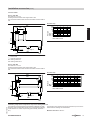
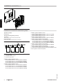
Pre-installation, multi boiler system
Design information (cont.)
Hydraulic cascade with low loss header
100
d
B
A
D
HV
HV
HV
HR
E
e
E
D
RP 1
g
C
f
c
b
a
882
HR
HR
h
k
l
4
Shown without the thermal insulation supplied
A
B
C
D
E Connection accessories with circulation pump
HR Heating return
HV Heating flow
Sensor well for flow temperature sensor
Air vent valve
Drain
Connectors for safety equipment Rp ½
Boiler
Number
Heating circuit connection
Boiler connection
Max. flow rate
Dimension
PN4/DN
G
m3/h
mm
mm
mm
mm
mm
mm
mm
mm
mm
mm
2x80 kW
3x45 kW
3x80 kW
4x10⁵ kW
6x 80 kW
8x 10⁵ kW
2x60 kW
80
1½
6.9
805
683
458
235
219
168
343
2110
430
595
2x10⁵ kW
80
1½
12.1
805
683
458
235
219
168
343
2110
430
595
3x60 kW
80
1½
10.3
805
683
458
235
219
168
343
2690
430
595
3x10⁵ kW
80
1½
18.1
805
683
458
235
219
168
343
2690
430
595
100
1½
24.1
1044
860
520
250
300
168
343
3491
430
595
6x 10⁵ kW
100
1½
36.2
1044
860
520
250
300
168
343
4651
430
595
100
1½
48.2
1044
860
520
250
300
168
343
5811
430
595
5822 432 GB
a
b
c
d
e
f
g
h
k
l
2x45 kW
VITODENS 200-W
VIESMANN
29
Design information (cont.)
Number
Heating circuit connection
Boiler connection
Max. flow rate
Dimension
PN4/DN
G
m3/h
mm
mm
mm
mm
mm
mm
mm
mm
mm
mm
a
b
c
d
e
f
g
h
k
l
(2x2) 45 kW
(2x2) 60 kW
80
1½
13.8
805
683
458
235
219
168
343
2112
–
–
Low loss header
■ DN 80
For installing 2- and 3-boiler systems in series up to 315 kW and 4boiler systems in block formation up to 240 kW.
Part no. Z010 305
■ DN 100
For installing 4- and 6-boiler systems in series up to 480 kW and 4boiler systems in block formation up to 420 kW.
Part no. Z010 306
■ DN 100
For installing 6- and 8-boiler systems in series up to 630 kW, and 6and 8-boiler systems in block formation up to 480 kW.
Part no. Z010 307
(2x2) 80 kW
(2x2) 105 kW
100
1½
24.1
1044
860
520
250
300
168
343
2331
–
–
(2x3) 80 kW
(2x3) 105 kW
100
1½
36.2
1044
860
520
250
300
168
343
2911
–
–
(2x4) 105 kW
100
1½
48.2
1044
860
520
250
300
168
343
3491
–
–
Comprising:
■ Low loss header with integral sensor well
■ Thermal insulation
■ Connection lines for hydraulic cascades with Rp ½ connections for
safety and control equipment
■ Air vent valve
■ Drain valve
Hydraulic cascade without low loss header
100
HV
HR HV
C
A
HR
C
B
a
HV
HR
RP 1
B
b
c
d
e
f
Shown without the thermal insulation supplied
A Heating circuit connecting kit
B Connectors for safety equipment Rp ½
30
VIESMANN
C Connection accessories with circulation pump
VITODENS 200-W
5822 432 GB
4
Boiler
Design information (cont.)
HR Heating return
HV Heating flow
Boiler
Number
Heating circuit
connection
Boiler connection
Max. flow rate
Dimension a
b
c
d
e
f
PN4/DN
G
m3/h
mm
mm
mm
mm
mm
mm
Boiler
Number
Heating circuit connection
Boiler connection
Max. flow rate
Dimension
a
b
c
d
e
f
PN4/DN
G
m3/h
mm
mm
mm
mm
mm
mm
2x45 kW
2x60 kW
65
2x80 kW
2x10⁵ kW
65
3x45 kW
3x60 kW
65
3x80 kW
3x10⁵ kW
65
4x10⁵ kW
8x 10⁵ kW
80
6x 80 kW
6x 10⁵ kW
100
1½
1½
1½
1½
1½
1½
1½
6.9
343
168
2110
430
555
440
12.1
343
168
2331
430
555
590
10.3
343
168
2690
430
555
440
18.1
343
168
2690
430
555
590
24.1
343
168
3491
430
555
590
36.2
343
168
4651
430
555
590
48.2
343
168
5811
430
555
590
100
(2x2) 45 kW
(2x2) 60 kW
80
(2x2) 80 kW
(2x2) 105 kW
100
(2x3) 80 kW
(2x3) 105 kW
100
(2x4) 105 kW
1½
13.8
343
168
2110
–
–
–
1½
24.1
343
168
2331
–
–
–
1½
36.2
343
168
2911
–
–
–
1½
48.2
343
168
3491
–
–
–
Comprising:
■ Connection lines for hydraulic cascades with Rp ½ connections for
safety and control equipment
■ Thermal insulation
5822 432 GB
Heating circuit connecting kit
■ DN 65
For installation in series of 2- and 3-boiler systems up to 315 kW.
Part no. 7453 093
■ DN 80
For installing 4- and 6-boiler systems in series up to 480 kW and 4boiler systems in block formation up to 420 kW.
Part no. 7453 094
■ DN 100
For installing 6- and 8-boiler systems in series up to 630 kW, and 6and 8-boiler systems in block formation up to 480 kW.
Part no. 7453 095
100
VITODENS 200-W
VIESMANN
31
4
Design information (cont.)
Installation in series with flue gas cascade
200
1500
F
A D
a
F
C
B
C
678
1750
678
HV
HR
760
E
b
430
c
4
580
Shown without the thermal insulation supplied
A Flue gas cascade
B Vitodens
C Vitotronic 300-K (can be fitted either to the left or the right)
The total length of all BUS cables (on site) should not exceed
50 m.
D
E
F
HR
HV
Note
Secure the flue gas cascade with suitable means.
Suspension from the ceiling is recommended. Observe the max. distance between fixing points F.
For details regarding the flue gas cascade, see page 24 and the technical guide on flue systems.
For further details regarding the hydraulic cascade, see page 28.
a
b
c
mm
mm
mm
2x45 kW
2x60 kW
176
301
595
2x80 kW
2x10⁵ kW
176
323
595
Multi boiler system standard delivery
■ Vitodens 200-W (2 to 8 boilers)
■ Additional boiler coding card for multi boiler system
■ Vitotronic 300-K cascade control unit
■ Cascade communication module for each boiler
■ Immersion temperature sensor
■ Self-supporting mounting frame
32
VIESMANN
3x45 kW
3x60 kW
207
301
595
3x80 kW
3x10⁵ kW
207
323
595
4x10⁵ kW
237
366
656
6x80 kW
6x10⁵ kW
387
406
696
8x10⁵ kW
447
406
696
■ Hydraulic cascade with thermal insulation
■ Connection accessory with circulation pumps (3-stage or high efficiency) and thermal insulation
Accessories (subject to order)
■ Low loss header in connection lines and thermal insulation
or
■ Heating circuit connecting kit with thermal insulation
VITODENS 200-W
5822 432 GB
Number of boilers
Self-supporting mounting frame
Hydraulic cascade
Flue gas cascade mounted on the ceiling
Heating return
Heating flow
Design information (cont.)
Installation in block formation with a flue gas cascade
200
F
F
1500
D
a
A
C
B
C
680
1750
680
HV
HR
E
760
c
b
4
580
Shown without the thermal insulation supplied
A Flue gas cascade
B Vitodens
C Vitotronic 300-K (can be fitted either to the left or the right)
The total length of all BUS cables (on site) should not exceed
50 m.
D
E
F
HR
HV
Note
Secure the flue gas cascade with suitable means.
Suspension from the ceiling is recommended. Observe the max. distance between fixing points F.
For details regarding the flue gas cascade, see page 24 and the technical guide on flue systems.
For further details regarding the hydraulic cascade, see page 28.
Boiler
5822 432 GB
a
b
c
mm
mm
mm
Multi boiler system standard delivery
■ Vitodens 200-W (4 to 8 boilers)
■ Additional boiler coding card for multi boiler system
■ Vitotronic 300-K cascade control unit
■ Cascade communication module for each boiler
■ Immersion temperature sensor
■ Hydraulic cascade with thermal insulation
VITODENS 200-W
(2x2) 45 kW
(2x2) 60 kW
176
680
1350
Self-supporting mounting frame
Hydraulic cascade
Flue gas cascade mounted on the ceiling
Heating return
Heating flow
(2x2) 80 kW
(2x2) 105 kW
176
843
1422
(2x3) 80 kW
(2x3) 105 kW
207
843
1422
(2x4) 105 kW
237
843
1422
■ Self-supporting mounting frame
■ Connection accessory with circulation pumps (3-stage or high efficiency) and thermal insulation
Accessories (subject to order)
■ Low loss header in connection lines and thermal insulation
or
■ Heating circuit connecting kit with thermal insulation
VIESMANN
33
Design information (cont.)
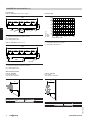
4.2 Condensate connection
Route the condensate drain pipe with a constant fall.
Route the condensate from the flue system (if equipped with a drain),
together with the boiler condensate directly or (if installed) via a neutralising system (accessory) to the public sewage system.
Note
A pipe vent valve must be installed between the siphon and the neutralising system.
A
A
B
Vitodens 200-W, 45 and 60 kW
Vitodens 200-W, 80 and 105 kW
A Drain hose (standard delivery for the Vitodens)
B Drain outlet kit (accessories)
A Drain hose (standard delivery for the Vitodens)
B Drain outlet kit (accessories)
Condensate drain and neutralisation
Drain the condensate created during the heating operation in the condensing boiler and in the flue pipe in accordance with appropriate regulations. During gas combustion, the condensate will have a pH
between 4 and 5.
Code of Practice ATV-DVWK-A 251 "Condensate from condensing
boilers", which is generally based on the local waste water regulations
[in Germany], defines the conditions for draining condensate from
condensing boilers into the public sewage system.
The composition of condensate drained from Vitodens condensing
boilers meets the requirements specified in Code of Practice ATVDVWK-A 251.
The condensate drain pipe to the sewer connection must be able to
be inspected.
It must be installed with a continuous fall and must contain a stench
trap. Also provide a suitable facility for sampling.
Condensate drain pipes must only be made from corrosion-resistant
materials (e.g. reinforced hose).
Never use any galvanised materials or those containing copper
for pipes, connection pieces etc.
A siphon is installed in the condensate drain to prevent flue gases
escaping.
Local waste water regulations and/or specific technical circumstances
may specify designs that vary from those described in the above
Codes of Practice.
It is advisable to contact your local authority responsible for waste
water management prior to installation, to find out about local regulations.
Condensate from gas combustion equipment up to 200 kW combustion output
Up to a rated heating output of 200 kW, the condensate from a gas
condensing boiler can generally be introduced into the public sewage
system without prior neutralisation.
Also ensure that your domestic drainage systems are made from
materials that are resistant to acidic condensate.
According to Code of Practice ATV-DVWK-A 251, these materials
include:
■ Clay pipes
■ Hard PVC pipes
■ PVC pipes
■ PE HD pipes
■ PP pipes
■ ABS/ASA pipes
■ Stainless steel pipes
■ Borosilicate pipes
Neutralising system
C
A
B
5822 432 GB
4
B
A Condensate drain
B Neutralising system
C Ventilation via the roof
34
VIESMANN
VITODENS 200-W
Design information (cont.)
The Vitodens can (if required) be supplied with a separate neutralising
system (accessory). Any condensate is piped to and treated in the
neutralising system.
The condensate drain pipe to the sewer connection must be able to
be inspected. It must be installed with a fall and stench trap on the
sewer side, and must provide a suitable facility for sampling.
Install a condensate lifting pump if the Vitodens has been installed
below the waste water anti-flooding level.
Condensate lifting pumps are available as accessories (see the Vitoset
pricelist).
Since the consumption of neutralising granulate depends on the operating mode of the system, determine the required top-up amount during the first year of operation by regular checks. It is feasible that one
fill may last longer than 12 months.
Neutralising system for single boiler systems with 45 and 60 kW
Part no. 9535 742
DN 40
145
400
Neutralising system for single boiler systems with 80 and 105 kW, and multi boiler systems
Part no. 7441 823
BC
140
70
110
165
A
410
421
230
4
A Inlet (DN 20)
B Outlet (DN 20)
C Overflow aperture
148
118
Part no. 7374 796
Automatic condensate lifting system for condensate with a pH value
≥ 2.7 from oil and gas condensing boilers.
Components:
■ Condensate container 0.5 l
■ Shaftless permanent magnet ball motor pump
■ Control unit for pump operation, display of operating conditions and
fault messages
■ 2 m long power cable with plug
■ Two 7 24 mm connection apertures for condensate inlet
The standard delivery comprises:
■ 6 m long drain hose 7 14 x 2 mm
■ Non-return valve
2000
Condensate lifting system
B
C
90
A
168
5822 432 GB
A Condensate inlet
B Condensate inlet with drain plug
C Condensate drain
Specification
Rated voltage
Rated frequency
Power consumption
VITODENS 200-W
230 V~
50 Hz
20 W
VIESMANN
35
Design information (cont.)
IP rating
Protection class
IP 44
F
Permissible medium temperature
Max. head
Max. capacity
Zero volt contact
+60 °C
45 kPa
450 l/h
N/C, breaking capacity
230 VA
4.3 Hydraulic connection
General information
4
Chemical anti-corrosion agents
Corrosion is generally avoided in correctly installed and operated
sealed unvented heating systems.
Never use chemical anti-corrosion agents.
Some manufacturers of plastic pipes recommend the use of chemical
additives. In such cases, only use anti-corrosion agents offered by the
heating trade that have been approved for boilers with DHW heating
via single-walled heat exchangers (instantaneous water heater or
DHW cylinder).
For this, observe the VDI Directive 2035 [or local regulations].
Heating circuits
For heating systems with plastic pipes, we recommend the use of
impermeable pipes to prevent the diffusion of oxygen through the pipe
walls.
Provide system separation in heating systems with plastic pipes to DIN
4726 that are permeable to oxygen. We supply a separate heat
exchanger for this.
Install a sludge separator in underfloor heating systems and systems
with a large water content; see the Viessmann Vitoset pricelist.
Even with condensing boilers, connect underfloor heating systems and
heating circuits with a very large water content (>15 l/kW) to the boiler
via a 3-way mixer; see technical guide "Control of underfloor heating
systems" or the relevant sample applications.
Install a temperature limiter in the flow of the underfloor heating circuit
to limit the maximum temperature. Observe the requirements of DIN
18560-2 [or local regulations].
Plastic pipework for radiators
We also recommend the installation of a temperature limiter to restrict
the maximum temperature of plastic pipes in heating circuits with radiators.
Safety valve
A safety valve in accordance with TRD 721 is part of the heating circuit
connection set (accessory) (opening pressure 4 bar).
Route the discharge pipe in accordance with EN 12828 into a drain
outlet (drain outlet kit available as an accessory). The drain outlet
incorporates a siphon as a stench trap.
Low water indicator
According to EN 12828, a low water indicator can be omitted for boilers
up to 300 kW, as long as heating can be reliably prevented in the case
of water shortage.
Viessmann Vitodens boilers are equipped with a low water indicator
(boil-dry protection). Tests have verified that the burner will be automatically switched off in the event of water shortage due to a leak in
the heating system and simultaneous burner operation, before the
boiler or the flue system reach unacceptably high temperatures.
36
VIESMANN
Attic heating centre
The installation of a low water indicator specified as compulsory to EN
12828 is not required when installing the Vitodens in an attic heating
centre.
The Vitodens condensing boilers are protected against water shortage
in accordance with EN 12828.
Water quality/Frost protection
Unsuitable fill and top-up water increases the level of deposits and
corrosion and may lead to boiler damage.
Regarding the quality and volume of heating water, incl. fill and top-up
water, observe VDI 2035.
■ Thoroughly flush the entire heating system prior to filling it with water.
■ Only use fill water of potable water quality.
■ Fill and top-up water with a water hardness in excess of the following
values must be softened, e.g. with the small softening system for
heating water (see the Viessmann Vitoset pricelist):
Total permissible hardness of the fill and top-up water
Total heating Specific system volume
output
kW
< 20 l/kW
≥ 20 l/kW to
≥ 50 l/kW
< 50 l/kW
≤ 50
≤ 3.0 mol/m3
≤ 2.0 mol/m3
< 0.02 mol/m3
(16.8 °dH)
(11.2 °dH)
(0.11 °dH)
> 50 to ≤ 200 ≤ 2.0 mol/m3
≤ 1.5 mol/m3
< 0.02 mol/m3
(11.2 °dH)
(8.4 °dH)
(0.11 °dH)
> 200 to
≤ 1.5 mol/m3
≤ 0.02 mol/m3 < 0.02 mol/m3
≤ 600
(8.4 °dH)
(0.11 °dH)
(0.11 °dH)
> 600
< 0.02 mol/m3 < 0.02 mol/m3 < 0.02 mol/m3
(0.11 °dH)
(0.11 °dH)
(0.11 °dH)
■ For systems with a specific system volume in excess of 20 litres/kW
heating output, use the output of the smallest boiler in multi boiler
systems.
■ An antifreeze additive suitable for heating systems can be added to
the fill water. The antifreeze manufacturer must verify its suitability,
since otherwise damage to gaskets and diaphragms can occur as
well as noise during heating operation. Viessmann accepts no liability for damage or consequential damage resulting from these causes.
When engineering the system, observe the following:
■ Install shut-off valves in different sections. This prevents the need
for draining all the heating water in the case of repairs or system
expansion.
■ In systems > 50 kW, install a water meter to record the volume of
the fill and top-up water. Record the amount of water filled into the
system and the water hardness.
Operating information:
■ Commission the system step by step, starting with the lowest boiler
output and a high heating water flow rate. This prevents a localised
concentration of limescale deposits on the boiler heating surfaces.
■ In multi boiler systems, start all boilers simultaneously to prevent the
entire limescale deposit settling in the heat transfer area of just one
boiler.
■ During expansion or repair work, only drain the necessary pipework
sections.
VITODENS 200-W
5822 432 GB
System design
Viessmann condensing boilers can generally be installed in any fully
pumped hot water heating system (sealed unvented system).
Connection sets with an integral circulation pump are available as
accessories.
Minimum system pressure 1.0 bar.
The boiler water temperature is limited to 82 ºC.
To keep distribution losses as low as possible, we recommend sizing
the heat distribution system for a maximum flow temperature of
70 ºC.
Design information (cont.)
■ Where water treatment is required, treat even the first fill of the heating system prior to commissioning. This also applies to any subsequent filling, e.g. when adding top-up water, after a repair or after
system expansion.
■ Filters, dirt traps and other discharge or separating facilities in the
heating water circuit must be checked, cleaned and activated more
frequently after commissioning or recommissioning, and later on as
required, subject to the water treatment applied (e.g. water softening).
Installation examples
For installation examples for the Vitodens 200-W, see "System examples".
Expansion vessels
In accordance with EN 12828, water heating systems must be equipped with an expansion vessel.
The size of the expansion vessel is subject to the heating system
specification and should be checked in each case.
Multi boiler systems
We recommend the installation of a low loss header in multi boiler
systems. For this, order the low loss header that is available as an
accessory. See page 28 and the Viessmann pricelist.
Losses resulting from the use of third party low loss headers are excluded from our liability.
On-site safety equipment should comply with EN 12828.
Information on sizing the plate heat exchanger:
■ The pressure drop in the plate heat exchanger must be lower than
the lowest pressure drop of connected heating circuits.
■ Fit a dirt trap on the secondary side of the plate heat exchanger.
■ When sizing, take the temperature differential of the plate heat
exchanger into account (max. flow temperature in a multi boiler system with Vitodens 200-W: 80 °C)
As an alternative to the low loss header, a suitably sized plate heat
exchanger may be used to provide system separation. In that case,
the flow temperature sensor should be arranged on the secondary side
of the plate heat exchanger. See the following system example.
4
M
A
M
A
A Flow temperature sensor
Low loss header
Application
Boiler
Design rules for system hydraulics:
■ When balancing the low loss header, adjust the flow rate on the
equipment side to approx. 10 to 30 % lower than the flow rate on the
system side (reducing the return temperature).
■ The low loss header should be sized for the max. flow rate that may
occur in the system as a whole.
The low loss header separates the heat source (boiler circuit) from the
downstream heating circuits.
Install a low loss header if the maximum flow rate in an individual case
is greater than the values shown in the table below.
Vitodens 200-W, 17 - 45 kW
Vitodens 200-W, 17 - 60 kW
Vitodens 200-W, 30 - 80 kW
Vitodens 200-W, 30 - 105 kW
We recommend installing a low loss header if the minimum flow rates
listed in the table below cannot be guaranteed.
Boiler
5822 432 GB
Vitodens 200-W, 17 - 45 kW
Vitodens 200-W, 17 - 60 kW
Vitodens 200-W, 30 - 80 kW
Vitodens 200-W, 30 - 105 kW
VITODENS 200-W
Max. flow rate
l/h
3500
3500
5700
5700
Min. flow rate
l/h
450
450
1300
1300
VIESMANN
37
Design information (cont.)
Low loss header for the Vitodens 200-W with 45 and 60 kW from
the Vitoset range
See the "Vitoset" pricelist.
e
Heating circuit
The heating circuit pumps to be installed on site must be able to deliver
the water volume in the heating circuits against their pressure drop,
and must be sized accordingly.
KV
HV
Principle of operation
b
KR
T3
Vprimary
T4
Vprimary
HR
Vsecondary
T2
Vsecondary
T1
T2
T3
T4
Qprimary
Qsecondary
Heating water volume, boiler circuit (approx. 10 - 30 %
less than Vsecondary)
Heating water volume, heating circuit
Flow temperature, boiler circuit
Return temperature, boiler circuit
Flow temperature, heating circuit
Return temperature, heating circuit
Amount of heat supplied by the boiler
Amount of heat transferred by the heating circuit
Vprimary
T1
T2
Qprimary
< Vsecondary
> T3
≃ T4
= Qsecondary
HR
HV
KR
KV
Heating return
Heating flow
Boiler return
Boiler flow
Flow rate
max.
Connections
- Female thread
- Male thread
- Flange
Dimen a
sion
b
c
d
e
m3/h
4
4
8
Rp
R
DN
mm
1
mm
mm
mm
mm
10
18
1¼
2
500
500
800
65
1400
80
1450
360
270
80
50
360
270
80
50
650
550
120
80
1000
1000
160
80
1000
1000
200
120
Low loss header for the Vitodens 200-W with 80 and 105 kW
See page 23.
Low loss header with distributor/manifold for multi boiler systems with Vitodens 200-W
For description and specification, see page 28.
Note
Suitable thermometers in the flow and return of the low loss header
make adjustments easier.
Control units
5.1 Vitotronic 100, type HC1B, for constant temperature operation
Structure and functions
Modular design
The control unit is integrated into the boiler.
The control unit comprises a standard unit, electronics modules and a
programming unit.
38
VIESMANN
Standard unit:
■ ON/OFF switch
■ Optolink laptop interface
■ Operating and fault display
■ Reset button
■ Fuses
5822 432 GB
5
a
T1
c
Boiler circuit
The circulation pump in the Vitodens must be able to supply the
required water volume against the (mostly low) pressure drop of the
boiler circuit; the pressure drop of the low loss header is negligible.
Subject to the water volume circulating in the boiler circuit, the respective residual head may be determined for sizing the internal pipe diameters using the pump diagram; alternatively the variable speed pump
can be adjusted accordingly.
Low loss header in conjunction with Divicon heating circuit distributor
For description and specification, see page 14.
d
For installation schemes in conjunction with low loss headers, see the
relevant sample application in the "System examples" document.
VITODENS 200-W
Control units (cont.)
■ Maintenance display
■ External starting and blocking (in conjunction with extension EA1)
Control characteristics
PI characteristics with modulating output.
Setting the heating programs
The heating system frost protection (see frost protection function)
applies to all heating programs.
The following heating programs can be selected:
■ Heating and DHW
■ Only DHW
■ Standby mode
Programming unit:
■ Easy operation through display with large font and depiction with
good contrast
■ Removable programming unit; can be mounted as option on the wall
with separate accessory
■ User prompts through pictographs
■ Control keys for:
– Navigation
– Confirmation
– Adjustments/menu
■ Setting the:
– Boiler water temperature
– DHW temperature
– Heating program
– Codes
– Actuator tests
– Test mode
■ Displaying:
– Boiler water temperature
– Set DHW temperature
– Operating details
– Diagnostic details
– Fault messages
Functions
■ Electronic boiler control unit for operation at a constant boiler water
temperature
■ Room temperature-dependent operation requires a Vitotrol 100,
type UTA, UTDB or UTDB-RF (according to EnEV [Germany])
■ Heating system frost protection
■ Anti-seizing pump protection
■ Integral diagnostic system
■ Cylinder thermostat with priority
■ Control of solar DHW heating and central heating backup in conjunction with the solar control module, type SM1
■ Auxiliary function for DHW heating (short-term heating to a higher
temperature)
Frost protection function
The frost protection function is active in all heating programs.
The burner is switched ON at a boiler water temperature of 5 ºC and
will be switched OFF again at a boiler water temperature of 20 ºC.
The circulation pump will be switched ON simultaneously with the
burner and switched OFF after a delay.
The DHW cylinder will be heated to approx. 20 ºC.
To protect the system against frost, the circulation pump may be started at certain intervals (up to 24 times per day) for periods of approx.
10 minutes.
Summer mode
Heating program "w"
The burner starts only when the DHW cylinder needs to be heated up
again.
Boiler water temperature sensor
The boiler water temperature sensor is connected to the control unit
and built into the boiler.
Specification
Sensor type
Permissible ambient temperature
– during operation
– during storage and transport
Viessmann NTC, 10 kΩ at
25 °C
5
0 to +130 °C
-20 to +70 °C
Cylinder temperature sensor
The standard delivery includes the DHW cylinder connection set.
Specification
Lead length
IP rating
Sensor type
Permissible ambient temperature
– during operation
– during storage and transport
3.75 m, fully wired
IP 32
Viessmann NTC, 10 kΩ at
25 °C
0 to +90 °C
–20 to +70 °C
Specification Vitotronic 100, type HC1B
230 V~
50 Hz
6A
I
Type 1 B to EN 60730-1
0 to +40 °C
Installation in living spaces or boiler rooms
(standard ambient conditions)
– during storage
and transport
–20 to +65 °C
Electronic temperature controller setting (heating mode) 82 °C (cannot be changed)
Setting range for
10 to 68 °C
the DHW temperature
5822 432 GB
Rated voltage
Rated frequency
Rated current
Safety category
Function
Permissible ambient temperature
– during operation
VITODENS 200-W
VIESMANN
39
Control units (cont.)
5.2 Vitotronic 200, type HO1B, for weather-compensated operation
Structure and functions
Modular structure
The control unit is integrated into the boiler.
The control unit comprises a standard unit, electronics modules and a
programming unit.
Standard unit:
■ ON/OFF switch
■ Optolink laptop interface
■ Operating and fault display
■ Reset button
■ Fuses
HC1
14°C
21°C
Boiler temperature
48 °C
■ Demand-dependent heating circuit pump and burner off control
■ Adjustment of a variable heating limit
■ Anti-seizing pump protection
■ Heating system frost protection
■ Integral diagnostic system
■ Maintenance display
■ Cylinder thermostat with priority
■ Control of solar DHW heating and central heating backup in conjunction with the solar control module, type SM1
■ Display of the solar energy yield
■ Auxiliary function for DHW heating (short-term heating to a higher
temperature)
■ Screed drying program
■ External starting and blocking (in conjunction with extension EA1)
The requirements of DIN EN 12831 for calculating the heating load are
met. To reduce the heat-up load, the reduced room temperature will
be raised in case of low outside temperatures. The flow temperature
will be raised for a limited time to reduce the heat-up time after a setback phase.
According to the Energy Saving Ordinance [Germany], the temperature in each room must be individually controlled, e.g. through thermostatic radiator valves.
Control characteristics
PI characteristics with modulating output.
Functions
■ Weather-compensated control of the boiler water and/or flow temperature
■ Control of one heating circuit without mixer and two heating circuits
with mixer
■ Electronic maximum and minimum temperature limit
40
VIESMANN
Setting the operating programs
The heating system frost protection (see frost protection function)
applies to all heating programs.
The following heating programs can be selected:
■ Heating and DHW
■ Only DHW
■ Standby mode
External heating program changeover in conjunction with EA1 extension.
Frost protection function
■ The frost protection function will be started when the outside temperature drops below approx. +1 °C.
With frost protection, the heating circuit pump is switched ON and
the boiler water is maintained at a lower temperature of approx.
20 °C.
The DHW cylinder will be heated to approx. 20°C.
■ The frost protection function will be stopped when the outside temperature rises above approx. +3 °C.
Summer mode
Heating program "w"
The burner starts only when the DHW cylinder needs to be heated up
again.
5822 432 GB
5
Programming unit:
■ Easy operation through:
– Plain text display with graphic ability
– Large font and black/white depiction for good contrast
– Context-sensitive help
– Removable programming unit; can be mounted as option on the
wall with separate accessory
■ With digital time switch
■ Control keys for:
– Navigation
– Confirmation
– Help and additional information
– Menu
■ Setting the:
– Room temperature
– Reduced room temperature
– DHW temperature
– Heating program
– Time programs for central heating, DHW heating and DHW circulation
– Economy mode
– Party mode
– Holiday program
– Heating curves
– Codes
– Actuator tests
– Test mode
■ Displaying:
– Boiler water temperature
– Set DHW temperature
– Operating details
– Diagnostic details
– Fault messages
Time switch
Digital time switch (integrated into the programming unit)
■ Individual day and seven-day program
■ Automatic summer/wintertime changeover
■ Automatic function for DHW heating and DHW circulation pump
■ Time, day and standard switching times for central heating, DHW
heating and the DHW circulation pump are factory-set
■ Switching times are individually programmable, i.e. up to four switching periods per day
Shortest switching interval: 10 minutes
Power reserve: 14 days
VITODENS 200-W
Control units (cont.)
Adjusting the heating curves (slope and level)
The Vitotronic 200 controls the boiler water temperature (= flow temperature of the heating circuit without mixer) and the flow temperature
of the heating circuits with mixer (in conjunction with the extension kit
for one heating circuit with mixer) in weather-compensated mode. The
boiler water temperature is automatically boosted by between 0 and
40 K higher than the currently required set flow temperature (delivered
condition 8 K).
The flow temperature required to reach a specific room temperature
depends on the heating system and the thermal insulation of the building to be heated.
Adjusting the heating curves matches the boiler water temperature and
the flow temperature to these operating conditions.
Heating curves:
The upper boiler water temperature is limited by the temperature limiter
and the temperature set at the electronic maximum thermostat.
The flow temperature cannot exceed the boiler water temperature.
1.6
Specification
Lead length
IP rating
Sensor type
3.75 m, fully wired
IP 32
Viessmann NTC, 10 kΩ at
25 °C
Permissible ambient temperature
– during operation
– during storage and transport
0 to +90 °C
–20 to +70 °C
Outside temperature sensor
Installation site:
■ North or north-western wall of the building
■ 2 to 2.5 m above the ground, for multi storey buildings in the upper
half of the second floor
Connection:
■ 2-core lead, length max. 35 m with a cross-section of 1.5 mm2 (copper).
■ Never route this lead immediately next to 230/400 V cables
1.4
80
1.2
1.0
70
60
0.8
50
80
Boiler water or
flow temperature in °C
90
3.4
3.2
3.0
2.8
2.6
2.4
2.2
2.0
1.8
Heating curve slope
Cylinder temperature sensor
The standard delivery includes the DHW cylinder connection set.
0.6
0.4
0.2
40
30
20
20 15 10 5 0 -5 -10 -15 -20 -25 -30
Outside temperature in °C
41
66
Specification
IP rating
Heating systems with low loss header
When using a hydraulic separation (low loss header), connect a temperature sensor for use in the low loss header.
Boiler water temperature sensor
The boiler water temperature sensor is connected to the control unit
and built into the boiler.
Specification
Sensor type
IP 43 to EN 60529
ensure through appropriate
design/installation
Viessmann NTC 10kΩ at
25 °C
Sensor type
Permissible ambient temperature during operation, storage and transport
−40 to +70 °C
Viessmann NTC, 10 kΩ at
25 °C
Permissible ambient temperature
– during operation
– during storage and transport
0 to +130 °C
-20 to +70 °C
Specification Vitotronic 200, type HO1B
Rated voltage
Rated frequency
Rated current
Safety category
Permissible ambient
temperature
– during operation
0 to +40 °C
Installation in living spaces or boiler rooms
(standard ambient conditions)
Electronic temperature
controller setting (heating mode)
Setting range for the
DHW temperature
Heating curve setting
range
Slope
Level
82 °C (cannot be changed)
10 to 68 °C
0.2 to 3.5
–13 to 40 K
–20 to +65 °C
5822 432 GB
– during storage and
transport
230 V~
50 Hz
6A
I
VITODENS 200-W
VIESMANN
41
5
Control units (cont.)
5.3 Vitotronic 300-K, type MW2B for multi boiler systems
Cascade control unit for the Vitodens 200-W with Vitotronic 100
Weather-compensated, digital cascade and heating circuit control
unit
■ For multi boiler systems with Vitodens 200-W
■ With boiler sequence strategy
■ For up to two heating circuits with mixers (extension for heating circuits 2 and 3 required as accessory).
Up to a further 32 Vitotronic 200-H heating circuit control units can
be connected via the LON BUS (LON module required; accessory)
■ For modulating operation in conjunction with the Vitotronic 100, type
HC1B
■ With cylinder temperature controller or control unit of a primary store
system with mixer assembly
■ Capable of communicating via LON BUS (LON communication module and terminators available as accessories)
■ With integral diagnostic system
Note
To improve the resilience against interference/faults, the components
of a control unit should be connected to the same phase.
Structure and function
Modular structure
The control unit comprises a standard unit, electronics modules and a
programming unit.
Standard unit:
■ ON/OFF switch
■ Emissions test switch
■ Optolink laptop interface
■ Operation and fault displays
■ Plug connection chamber
– Connection of external equipment via a system plug
– Plug the connectors directly into the front of the open control unit
– Connection of three-phase consumers via additional contactors
The requirements of DIN EN 12831 for calculating the heating load are
met. To reduce the heat-up load, the reduced room temperature will
be raised in case of low outside temperatures. The flow temperature
will be raised for a limited time to reduce the heat-up time after a setback phase.
According to the Energy Saving Ordinance [Germany], the temperature in each room must be individually controlled, e.g. through thermostatic radiator valves.
5822 432 GB
5
Programming unit:
■ Easy operation through:
– Plain text display with graphic ability
– Large font and black/white depiction for good contrast
– Context-sensitive help
■ With digital time switch
■ Control keys for:
– Navigation
– Confirmation
– Help and additional information
– Extended menu
■ Setting the:
– Room temperature
– Reduced room temperature
– DHW temperature
– Heating program
– Time programs for central heating, DHW heating and DHW circulation
– Economy mode
– Party mode
– Holiday program
– Heating curves
– Codes
– Actuator tests
– Test mode
■ Displaying:
– Flow temperature
– DHW temperature
– Information
– Operating details
– Diagnostic details
– Fault messages
Functions
■ Weather-compensated regulation of the system/boiler water temperature in a multi boiler system with Vitodens 200-W with
Vitotronic 100, type HC1B (modulating) and the flow temperature of
the heating circuits with mixers
■ Control of boilers (with a Vitotronic 100, type HC1B) in accordance
with a freely selectable boiler sequence strategy
■ Electronic maximum temperature limiter
■ Demand-dependent heating circuit pump shutdown
■ Adjustment of a variable heating limit
■ Pump anti-seizing protection
■ Central fault message
■ Integral diagnostic system
■ Adaptive cylinder temperature controller with priority (heating circuit
pump OFF, mixer closed)
■ Auxiliary function for DHW heating (short term heating to a higher
temperature)
■ Control of a primary store system with a regulated 3-way mixing
valve
■ Screed drying, for underfloor heating systems
42
VIESMANN
VITODENS 200-W
Control units (cont.)
DHW heating in a multi boiler system
A
M
M
A Vitotronic 300-K
Setting heating programs
The heating system frost protection (see frost protection function)
applies to all heating programs.
You can select the following heating programs with the program
keys:
■ Heating and DHW
■ Only DHW
■ Standby mode
Optional external changeover of heating program for all heating circuits together or for selected heating circuits only.
5822 432 GB
Frost protection function
■ The frost protection function will be started when the outside temperature drops below approx. +1 °C.
With frost protection, the heating circuit pump is switched ON and
the boiler water is maintained at a lower temperature of approx.
20 °C.
The DHW cylinder will be heated to approx. 20°C.
■ The frost protection function will be stopped when the outside temperature rises above approx. +3 °C.
90
80
70
60
50
40
30
1.6
Heating curve slope
3.4
3.2
3.0
2.8
2.6
2.4
2.2
2.0
1.8
Time switch
Digital time switch (integrated into the programming unit)
■ Single and 7-day program, annual calendar
■ Automatic summer/wintertime changeover
■ Automatic function for DHW heating and DHW circulation pump
■ Time, day and standard switching times for central heating, DHW
heating and the DHW circulation pump are factory-set
■ Switching times are individually programmable, i.e. up to four switching periods per day
Shortest switching interval: 10 min
Power reserve: 14 days
Heating curve setting (slope and level)
Subject to heating system:
■ The Vitotronic controls the flow temperature of up to 2 heating circuits with mixers in weather-compensated mode
■ The Vitotronic automatically regulates the system/flow temperature
to 0 to 40 K (delivered condition 8 K) higher than the currently highest
set flow temperature
The flow temperature required to reach a specific room temperature
depends on the heating system and the thermal insulation of the building to be heated.
Adjusting the heating curves matches the system flow temperature
and the heating circuit flow temperature to these conditions.
Boiler water or
flow temperature in °C
Control characteristics
■ PI characteristics with three-point output
■ Setting range for heating curves:
– Slope: 0.2 to 3.5
– Level: –13 to 40 K
– Max. limit: 1 to 127 °C
– Min. limit: 1 to 127 °C
– Differential temperature for a heating circuit with mixer: 0 to 40 K
■ Set DHW temperature range:
10 to 60 °C, adjustable between 10 and 95 °C (available temperature
limited by the max. boiler flow temperature).
1.4
5
1.2
1.0
0.8
0.6
0.4
0.2
20
20 15 10 5 0 -5 -10 -15 -20 -25 -30
Outside temperature in °C
The upper flow temperature is limited by temperature controller "R"
and the electronically set maximum temperature of the Vitotronic 100
boiler control units, type HC1B.
Outside temperature sensor
Installation site:
■ North or north-western wall of the building
■ 2 to 2.5 m above the ground, for multi storey buildings in the upper
half of the second floor
Connection:
■ 2-core lead, length max. 35 m with a cross-section of 1.5 mm2 (copper).
■ Never route this lead immediately next to 230/400 V cables
Summer mode
("DHW only")
One or more burners start when the DHW cylinder needs to be heated
up (controlled by the cylinder temperature controller).
VITODENS 200-W
VIESMANN
43
Control units (cont.)
Inserted into the sensor well of the low loss header or secured with a
tie.
80
Specification
Lead length
IP rating
Sensor type
41
Permissible ambient temperature
– during operation
– during storage and transport
66
5.8 m, fully wired
IP 32 to EN 60529
Viessmann NTC, 10 kΩ at
25 °C
0 to +90 °C
–20 to +70 °C
Cylinder temperature sensor
Specification
IP rating
IP 43 to EN 60529
ensure through appropriate
design/installation
Viessmann NTC 10kΩ at
25 °C
Sensor type
Permissible ambient temperature during operation, storage and transport
−40 to +70 °C
Immersion temperature sensor
To capture the common flow temperature of the multi boiler system.
Specification
Lead length
IP rating
Sensor type
Permissible ambient temperature
– during operation
– during storage and transport
5.8 m, fully wired
IP 32 to EN 60529
Viessmann NTC, 10 kΩ at
25 °C
0 to +90 °C
–20 to +70 °C
Specification, Vitotronic 300-K
Rated voltage:
Rated frequency:
Rated current:
Power consumption:
Safety category:
IP rating:
0 to +40 °C for use in the
living space or boiler room
(standard ambient conditions)
– during storage and transport:
Rated relay output breaking capacity:
– Heating circuit pumps or heat
exchanger set sÖ:
– Circulation pump for cylinder heating
sA:
– DHW circulation pump sK:
– Distribution pump sL:
– Central fault message gÖ:
– Motor, 3-way mixing valve, primary
store system
or
Mixer motor gS:
– Overall max.
–20 to +65 °C
4(2) A 230 V~
4(2) A 230 V~
4(2) A 230 V~
4(2) A 230 V~
4(2) A 230 V~
0.2(0.1) A 230 V~
6 A 230 V~
Dimensions
584
172
A
297
A
B
B
108
A Vitotronic 300-K
B Mounting panel
Delivered condition Vitotronic 300-K
■ Programming unit with backlit plain text prompts
■ Cascade communication module (corresponding to the number of
Vitodens)
■ Outside temperature sensor
■ Flow temperature sensor
■ Cylinder temperature sensor
■ Mounting panel
44
VIESMANN
The control unit is fitted to the wall with a mounting panel.
To control the heating circuits with mixers, the extension for heating
circuits 2 and 3 is required (accessory).
An extension kit (accessories) is required for each heating circuit with
mixer.
The LON communication module and BUS terminators are available
as accessories to enable communication.
VITODENS 200-W
5822 432 GB
5
Function:
Permissible ambient temperature
– during operation:
230 V ~
50 Hz
6A
10 W
I
IP 20 D to EN 60529,
ensure through design/
installation
Type 1B to EN 60730-1
Control units (cont.)
Heating system with DHW cylinder
Order the circulation pump with check valve or the Vitotrans 222 primary store system separately.
5.4 Vitotronic accessories
Assignment to control unit types
Vitotronic
Type
Accessories
Vitotrol 100, type UTA
Vitotrol 100, type UTDB
External extension H4
Vitotrol 100, type UTDB-RF
Vitotrol 200A
Vitotrol 300A
Room temperature sensor for Vitotrol 300A
Mounting base for programming unit
Radio clock receiver
Immersion temperature sensor
Vitocom 100
Extension for heating circuits with mixers 2 and 3
Extension kit for one heating circuit with mixer
Extension kit for one heating circuit with mixer with integral mixer
motor
Extension kit for one heating circuit with mixer with separate mixer
motor
Mixer motor
Solar control module, type SM1
Immersion temperature sensor
Immersion thermostat
Contact thermostat
LON communication module
LON connecting cable
LON coupling
LON plug-in connector
LON socket
Terminator
KM BUS distributor
Internal extension H1
Internal extension H2
Extension AM1
Extension EA1
100
HC1B
200
HO1B
300-K
MW2B
x
x
x
x
x
x
x
x
x
x
x
x
x
x
x
x
x
x
x
x
x
x
x
x
x
x
x
x
x
x
x
x
x
x
x
x
x
x
x
x
x
x
x
x
x
x
x
x
x
x
x
x
x
x
x
x
5
x
Vitotrol 100, type UTA
Room thermostat
■ With switching output (two-point output)
■ With analog time switch
■ With adjustable individual day program
■ Standard switching times are factory-set (individually programmable)
■ Shortest switching interval 15 minutes
5822 432 GB
Install the Vitotrol 100 in the main living room on an internal wall opposite radiators, but not inside shelf units, recesses, immediately by a
door or a heat source (e.g. direct sunlight, fireplace, TV set, etc.).
Control unit connection:
3-core cable with a cross-section of 1.5 mm2 (without green/yellow) for
230 V~.
VITODENS 200-W
34
15
0
90
Part no. 7170 149
Specification
Rated voltage
Rated breaking capacity of the contact
Protection
230 V/50 Hz
6(1) A 250 V~
IP 20 to EN 60529
safeguard through appropriate
design and installation
VIESMANN
45
Control units (cont.)
Permissible ambient temperature
– during operation
– during storage and transport
Set value range for standard and
reduced mode
Set room temperature in standby
mode
0 to +40 °C
-20 to +60 °C
10 to 30 °C
6 °C
Vitotrol 100, type UTDB
Part no. Z007 691
Specification
Rated voltage
Room temperature controller
■ With switching output (two-point output)
■ With digital time switch
■ With individual and seven-day programs
■ Programming unit with user prompts:
– 3 preselected time programs, individually adjustable
– Constant manual mode with adjustable set room temperature
– Frost protection mode
– Holiday program
■ With selector keys for party and economy mode
Function
Permissible ambient temperature
– during operation
– during storage and transport
Setting range
– Comfort temperature
– Setback temperature
– Frost protection temperature
Power reserve during battery
change
6(1) A, 230 V~
1 mA, 5 V–
IP 20 to EN 60529;
ensure through appropriate
design/installation
RS Type 1B to EN 60730-1
0 to +40 °C
–25 to +65 °C
10 to 40 °C
10 to 40 °C
5 °C
3 min
29
Installation in the main living room on an internal wall opposite radiators. Never install inside shelving units, in recesses, or immediately by
a door or heat source (e.g. direct sunlight, fireplace, TV set, etc.).
Operation without power supply (two 1.5 V round alkaline batteries,
type LR6/AA, which run for approx.1.5 years).
Control unit connection:
2-core lead with a cross-section of 0.75 mm2 for 230 V~.
Rated breaking capacity of the zero
volt contact
– max.
– min.
IP rating
3 V–
Battery LR6/AA
130
5
80
External extension H4
Part no. 7197 227
Connection extension for connecting the Vitotrol 100, type UTDB or
24 V clock thermostats via a LV cable.
With cable (0.5 m long) and plug for the connection to the
Vitotronic 100.
0
13
45
72
Specification
Rated voltage
Output voltage
Rated frequency
Power consumption
Load 24 V~ (max.)
Protection class
IP rating
Permissible ambient temperature
– during operation
0 to +40 °C
Installation in living spaces or
boiler rooms (standard ambient conditions)
-20 to +65 °C
5822 432 GB
– during storage and transport
230 V~
24 V~
50 Hz
2.5 W
10 W
I
IP 41
46
VIESMANN
VITODENS 200-W
Control units (cont.)
Vitotrol 100, type UTDB-RF
Part no. Z007 692
Room temperature controller with integral wireless transmitter and one
receiver
■ With digital time switch
■ With individual and seven-day programs
■ Programming unit with user prompts:
– 3 preselected time programs, individually adjustable
– Constant manual mode with adjustable set room temperature
– Frost protection mode
– Holiday program
■ With selector keys for party and economy mode
Installation in the main living room on an internal wall opposite radiators. Never install inside shelving units, in recesses, or immediately by
a door or heat source (e.g. direct sunlight, fireplace, TV set, etc.).
Room temperature controller operation without power supply (two 1.5
V round alkaline batteries, type LR6/AA, which run for approx.
1.5 years).
Receiver with relay state indication.
Connection of the receiver to the control unit (subject to control unit
type):
■ 4-core cable with a cross-section of 1.5 mm2 for 230 V~
or
■ 3-core cable without green/yellow core for 230 V~
or
■ 2-core lead with a cross section of 0.75 mm2 for LV for the connection
to the control unit, plus an additional 2-core cable for the 230 V~
power supply
Specification, room temperature controller
Rated voltage
3 V–
Transmission frequency
868 MHz
Transmission
< 10 mW
Range
approx. 25 to 30 m inside
buildings, subject to construction
IP rating
IP 20 to EN 60529;
ensure through appropriate
design/installation
Function
RS Type 1B to EN 60730-1
Permissible ambient temperature
– during operation
0 to +40 °C
– during storage and transport
–25 to +65 °C
Setting range
– Comfort temperature
10 to 40 °C
– Setback temperature
10 to 40 °C
– Frost protection temperature
5 °C
Power reserve during battery
change
3 min
Specification, receiver
Operating voltage
Rated breaking capacity of the zero
volt contact
– max.
– min.
IP rating
Protection class
30
29
Permissible ambient temperature
– during operation
– during storage and transport
230 V~ ± 10 % 50 Hz
6(1) A, 230 V~
1 mA, 5 V–
IP 20 to EN 60529;
ensure through appropriate
design/installation
II to EN 60730-1 subject to correct installation
0 to +40 °C
–25 to +65 °C
80
13
0
80
130
5
Notes regarding room temperature hook-up (RS function) for remote control units
Never activate the RS function for underfloor heating circuits (inertia).
In heating systems with a heating circuit without mixer and heating
circuits with mixer, the RS function must only affect the heating circuit
with mixer.
Information regarding the Vitotrol 200A and 300A
One Vitotrol 200A or one Vitotrol 300A can be used for every heating
circuit in a heating system.
The Vitotrol 200A can regulate one heating circuit; the Vitotrol 300A
up to three heating circuits.
Up to two remote controls may be connected to the control unit.
Vitotrol 200A
5822 432 GB
Part no. Z008 341
KM BUS subscriber
VITODENS 200-W
Functions:
■ Display of room temperature, outside temperature and the operating
condition.
■ Setting the standard room temperature (day temperature) and operating program via the standard display.
VIESMANN
47
20
Note
The reduced room temperature (night temperature) is set at the control unit.
,5
Control units (cont.)
■ Party and economy mode can be enabled via keys.
■ Only for heating circuit with mixer:
fitted room temperature sensor for room temperature hook-up
Note
For room temperature hook-up, the Vitotrol 200A must be installed
in the living space (lead room).
97
14
8
Installation site:
■ Weather-compensated mode:
Installation anywhere in the building.
■ Room temperature hook-up:
Installation in the main living room on an internal wall opposite radiators. Never install inside shelving units, in recesses, or immediately
by a door or heat source (e.g. direct sunlight, fireplace, TV set, etc.).
The fitted room temperature sensor captures the actual room temperature and effects any necessary correction of the flow temperature.
Connection:
■ 2-core lead, length max. 50 m (even if connecting several remote
control units)
■ Never route this lead immediately next to 230/400 V cables
■ LV plug as standard delivery
Specification
Power supply via KM BUS
Power consumption
Safety category
IP rating
0.2 W
III
IP 30 to EN 60529
ensure through appropriate design/installation
Permissible ambient temperature
– during operation
– during storage and transport
Set room temperature range
0 to +40 °C
−20 to +65 °C
3 to 37 °C
Vitotrol 300A
15
5
97
Note
For room temperature hook-up, the Vitotrol 300A must be installed
in the living space (lead room).
Installation site:
■ Weather-compensated mode:
Installation anywhere in the building.
■ Room temperature hook-up:
Installation in the main living room on an internal wall opposite radiators. Never install inside shelving units, in recesses, or immediately
by a door or heat source (e.g. direct sunlight, fireplace, TV set, etc.).
The fitted room temperature sensor captures the actual room temperature and effects any necessary correction of the flow temperature.
48
VIESMANN
Specification
Power supply via KM BUS
Power consumption
Safety category
IP rating
Permissible ambient temperature
– during operation
– during storage and transport
Set room temperature range
0.5 W
III
IP 30 to EN 60529
ensure through appropriate design/installation
0 to +40 °C
−20 to +65 °C
3 to 37 °C
VITODENS 200-W
5822 432 GB
5
Functions:
■ Displaying:
– Room temperature
– Outside temperature
– Heating program
– Operating condition
– Solar yield as graphic display
■ Settings:
– Set room temperatures for standard mode (day temperature) and
reduced mode (night temperature) via the standard display
– Heating program, switching times for heating circuits, DHW heating and DHW circulation pump plus further settings via plain text
menu on the display
■ Party and economy mode can be enabled via the menu
■ Only for heating circuit with mixer:
fitted room temperature sensor for room temperature hook-up
Connection:
■ 2-core lead, length max. 50 m (even if connecting several remote
control units)
■ Never route this lead immediately next to 230/400 V cables
■ LV plug as standard delivery
20
,5
Part no. Z008 342
KM BUS subscriber
Control units (cont.)
Room temperature sensor
Part no. 7438 537
Separate room temperature sensor as supplement to the Vitotrol
300A; to be used if the Vitotrol 300A cannot be installed inside the main
living room or in a suitable position where the unit could capture and
adjust the temperature.
Installation in the main living room on an internal wall opposite radiators. Never install inside shelving units, in recesses, or immediately by
a door or heat source (e.g. direct sunlight, fireplace, TV set, etc.).
Connect the room temperature sensor to the Vitotrol 300A.
Connection:
■ 2-core lead with a cross-section of 1.5 mm2 (copper)
■ Lead length from the remote control up to 30 m
■ Never route this lead immediately next to 230/400 V cables
Specification
Safety category
IP rating
Sensor type
Permissible ambient temperature
– during operation
– during storage and transport
III
IP 30 to EN 60529
ensure through appropriate design/installation
Viessmann NTC, 10 kΩ at
25 °C
0 to +40 °C
−20 to +65 °C
0
□8
20
Mounting base for programming unit
Part no. 7299 408
To be able to freely position the programming unit of the control unit
anywhere outside the appliance.
To be fitted directly to the wall or a surface box.
Distance from the boiler: Observe the lead length incl. plugs of 5 m.
5
110
0
16
Comprising:
■ Wall mounting base with fixing materials
■ 5 m long cable with plugs
■ Cover for the control unit aperture on the boiler
20
41
66
5822 432 GB
Part no. 7450 563
For receiving the DCF 77 time signal (location: Mainflingen near Frankfurt/Main).
Radio controlled setting of time and date.
Install on an outside wall, facing the transmitter. The reception may be
reduced by metallic elements in the building structure, e.g. steel reinforced concrete, neighbouring buildings and sources of electro-magnetic interference, e.g. HV and public transport lines.
Connection:
■ 2-core lead, length up to 35 m with a cross-section of 1.5 mm2(copper)
■ Never route this lead immediately next to 230/400 V cables.
80
Radio clock receiver
VITODENS 200-W
VIESMANN
49
Control units (cont.)
Vitocom 100, type GSM
Total length of all KM BUS subscriber cables up to 50 m.
72
13
0
50
■ Without SIM card
Part no. Z004594
■ With contract SIM card for the operation of the Vitocom 100 via
mobile phone
Part no. Z004615
Note
For information regarding terms of contract, see "www.viessmann.de/
vitocom-100".
Functions:
■ Remote switching via GSM mobile phone networks
■ Remote scanning via GSM mobile phone networks
■ Remote monitoring via SMS to 1 or 2 mobile phones
■ Remote monitoring of additional systems via digital input (230 V)
Configuration:
Mobile phones via SMS
Standard delivery:
■ Vitocom 100 (subject to order with or without SIM card)
■ Power cable with standard Euro plug (2.0 m long)
■ GSM aerial (3.0 m long), magnetic foot and adhesive pad
■ KM BUS cable (3.0 m long)
On-site requirements:
Good reception for GSM communication with the selected mobile
phone operator.
Specification
Rated voltage
Rated frequency
Rated current
Power consumption
Safety category
IP rating
Function
Permissible ambient temperature
– during operation
– during storage and transport
On-site connection
Fault input DE 1
230 V ~
50 Hz
15 mA
4W
II
IP 41 to EN 60529; ensure
through design/installation
Type 1B to EN 60 730-1
0 to +55 °C
Installation in living spaces or
boiler rooms (standard ambient conditions)
–20 to +85 °C
230 V ~
Mixer extension kit with integral mixer motor
IP rating
Components:
■ Mixer PCB with mixer motor for Viessmann mixer DN 20 to 50 and
R ½ to 1¼
■ Flow temperature sensor (contact temperature sensor)
■ Plug for connecting the heating circuit pump
■ Power cable (3.0 m long) with plug
■ BUS cable (3.0 m long) with plug
Safety category
Permissible ambient temperature
– during operation
– during storage and transport
Rated breaking capacity of the relay
output for heating circuit pump sÖ
Torque
Runtime for 90 ° ∢
The mixer motor is mounted directly onto the Viessmann mixer DN 20
to 50 and R ½ to 1¼.
0 to +40 °C
–20 to +65 °C
2(1) A 230 V~
3 Nm
120 s
42
60
0
18
IP 32D to EN 60529
ensure through appropriate
design/installation
I
Flow temperature sensor (contact temperature sensor)
Mixer PCB with mixer motor
13
0
66
Specification
Lead length
IP rating
Sensor type
Specification
Rated voltage
Rated frequency
Rated current
Power consumption
50
VIESMANN
230 V~
50 Hz
2A
5.5 W
Permissible ambient temperature
– during operation
– during storage and transport
2.0 m, fully wired
IP 32D to EN 60529
ensure through appropriate
design/installation
Viessmann NTC, 10 kΩ at
25 °C
0 to +120 °C
–20 to +70 °C
VITODENS 200-W
5822 432 GB
Secured with a tie.
160
5
Part no. 7301 063
KM BUS subscriber
Control units (cont.)
Mixer extension kit for separate mixer motor
Part no. 7301 062
KM BUS subscriber
For the connection of a separate mixer motor.
Components:
■ Mixer PCB for the connection of a separate mixer motor
■ Flow temperature sensor (contact temperature sensor)
■ Plug for connecting the heating circuit pump and the mixer motor
■ Power cable (3.0 m long) with plug
■ BUS cable (3.0 m long) with plug
Safety category
Permissible ambient temperature
– during operation
– during storage and transport
Rated relay output breaking capacity
Heating circuit pump Ös
Mixer motor
Required runtime of the mixer motor
for 90 ° ∢
I
Mixer PCB
Flow temperature sensor (contact temperature sensor)
0 to +40 °C
–20 to +65 °C
2(1) A 230 V~
0.1 A 230 V~
approx. 120 s
140
60
42
66
0
18
Secured with a tie.
58
Specification
Lead length
IP rating
Specification
Rated voltage
Rated frequency
Rated current
Power consumption
IP rating
230 V~
50 Hz
2A
1.5 W
IP 20D to EN 60529
ensure through appropriate
design/installation
Sensor type
Permissible ambient temperature
– during operation
– during storage and transport
5.8 m, fully wired
IP 32D to EN 60529
ensure through appropriate
design/installation
Viessmann NTC, 10 kΩ at
25 °C
0 to +120 °C
–20 to +70 °C
5
Extension kit for one heating circuit with mixer in conjunction with Divicon heating circuit distributor
Part no. 7424 958
Components:
■ Mixer PCB with mixer motor
■ Flow temperature sensor (immersion sensor for installation in the
Divicon)
■ Connection plug for heating circuit pump, power supply, flow temperature sensor and KM BUS connection
Specification
Rated voltage
Rated frequency
Rated current
Power consumption
IP rating
Mixer PCB
Protection class
Permissible ambient temperature
– during operation
– during storage and transport
Rated relay output breaking capacity
Heating circuit pump sÖ
Runtime for 90 ° ∢
0
18
13
0
230 V~
50 Hz
2A
5.5 W
IP 32 D to EN 60 529,
ensure through appropriate
design/installation
I
0 to +40 °C
–20 to +65 °C
2(1) A 230 V~
approx. 120 s
5822 432 GB
160
Flow temperature sensor (immersion sensor)
VITODENS 200-W
VIESMANN
51
Control units (cont.)
Specification
Lead length
IP rating
Sensor type
0.9 m, fully wired
IP 32 to EN 60529; ensure
through appropriate design
and installation
Viessmann NTC, 10 kΩ at
25 °C
Permissible ambient temperature
– during operation
– during storage and transport
0 to +120 °C
−20 to +70 °C
Vitotronic 300-K extension for heating circuits with mixers 2 and 3
Part no. 7164 403
PCB for installation in the Vitotronic 300-K, type MW2B.
For controlling two heating circuits with mixers.
■ With connections for mixer motors, flow temperature sensors (NTC
10 kΩ) and heating circuit pumps.
■ Plug for mixer motor and heating circuit pump for each heating circuit.
Extension kit for one heating circuit with mixer for the Vitotronic 300-K
Part no. 7441 998
Components:
■ Mixer motor
■ Flow temperature sensor (contact temperature sensor), lead length
5.8 m, fully wired
■ Plug for connecting the heating circuit pump
■ Mixer motor terminals
■ Connecting cable (4.0 m long)
The mixer motor is mounted directly onto the mixer DN 20 to 50 or
R ½ to 1¼.
Permissible ambient temperature
– during operation
– during storage and transport
Torque
Runtime for 90 ° ∢
Flow temperature sensor (contact sensor)
42
Secured with a tie.
130
Specification
IP rating
Sensor type
Specification, extension kit
Rated voltage
Rated frequency
Power consumption
Safety category
IP rating
Permissible ambient temperature
– during operation
– during storage and transport
230 V~
50 Hz
2.5 W
I
IP 32D to EN 60529;
ensure through design/
installation
IP 32D to EN 60529
ensure through design/installation
Viessmann NTC, 10 kΩ at
25 °C
0 to +120 °C
–20 to +70 °C
Mixer motors
See datasheet "Control unit accessories".
Immersion thermostat
Part no. 7151 728
May be used as a maximum temperature limiter for underfloor heating
systems.
The temperature limiter is installed into the heating flow and switches
the heating circuit pump OFF if the flow temperature is too high.
5822 432 GB
5
66
90
0
60
Mixer motor
18
0 to +40 °C
–20 to +65 °C
3 Nm
120 s
52
VIESMANN
VITODENS 200-W
Control units (cont.)
13
0
200
95
72
Specification
Lead length
Setting range
Switching differential
Breaking capacity
Setting scale
Stainless steel sensor well
DIN reg. no.
4.2 m, fully wired
30 to 80 °C
max. 11 K
6(1.5) A 250 V~
inside the casing
R ½" x 200 mm
DIN TR 116807
or
DIN TR 96808
Contact thermostat
Part no. 7151 729
May be used as a maximum temperature limiter for underfloor heating
systems (only in conjunction with metallic pipes).
The temperature limiter is installed into the heating flow and switches
the heating circuit pump OFF if the flow temperature is too high.
0
13
4.2 m, fully wired
30 to 80 °C
max. 14 K
6(1.5) A 250V~
inside the casing
DIN TR 116807
or
DIN TR 96808
95
72
Specification
Lead length
Setting range
Switching differential
Breaking capacity
Setting scale
DIN reg. no.
5
Immersion temperature sensor
Part no. 7179 488
To capture the low loss header temperature.
Specification
Lead length
IP rating
Sensor type
Permissible ambient temperature
– during operation
– during storage and transport
3.75 m, fully wired
IP 32
NTC 10 kΩ at 25 °C
0 to +90 °C
–20 to +70 °C
Solar control module, type SM1
Part no. 7429 073
Specification
5822 432 GB
Construction
The solar control module contains:
■ PCB
■ Connection terminals
– 4 sensors
– Solar circuit pump
– KM BUS
– Power supply (on-site ON/OFF switch)
■ PWM output for controlling the solar circuit pump
■ 1 relay for switching a pump or a valve
VITODENS 200-W
Collector temperature sensor
For connection inside the appliance.
On-site extension of the connecting lead:
■ 2-core lead, length up to 60 m with a cross-section of 1.5 mm2 (copper)
■ Never route this lead immediately next to 230/400 V cables
Lead length
IP rating
Sensor type
Permissible ambient temperature
– during operation
– during storage and transport
2.5 m
IP 32 to EN 60529; ensure
through design/installation
Viessmann NTC 20 kΩ at
25 °C
−20 to +200 °C
−20 to +70 °C
VIESMANN
53
Control units (cont.)
Lead length
IP rating
Sensor type
Permissible ambient temperature
– during operation
– during storage and transport
3.75 m
IP 32 to EN 60529; ensure
through design/installation
Viessmann NTC 10 kΩ at
25 °C
0 to +90 °C
−20 to +70 °C
For systems with Viessmann DHW cylinders, the cylinder temperature
sensor is installed in the threaded elbow (standard delivery or accessory for the respective DHW cylinder) in the heating water return.
Functions
■ Switching the solar circuit pump
■ Electronic limiter for the temperature in the DHW cylinder (safety
shutdown at 90 °C)
■ Collector safety shutdown
■ Central heating backup is controlled in conjunction with a multi mode
heating water buffer cylinder
■ The heating of two consumers is controlled via a collector array
■ Switching an additional pump or valve via relay
■ Second temperature differential control or thermostat function
■ Solar circuit pump speed control via wave pack control or solar circuit
pump with PWM input (Grundfos)
■ Suppression of DHW cylinder reheating by the boiler (auxiliary function for DHW heating is possible)
■ Suppression of reheating for central heating by the boiler with central
heating backup
■ Heating up of the solar-heated preheat stage (for DHW cylinders with
a total capacity of ≥ 400 l)
■ Output statement and diagnostic system
0
18
58
Rated voltage
Rated frequency
Rated current
Power consumption
Safety category
IP rating
Function
Permissible ambient temperature
– during operation
– during storage and transport
Rated relay output breaking
capacity
– Semi-conductor relay 1
– Relay 2
– Total
230 V~
50 Hz
2A
1.5 W
I
IP 20 to EN 60529; ensure
through design/installation
Type 1B to EN 60730-1
0 to +40 °C use in the living
space or boiler room (standard
ambient conditions)
−20 to +65 °C
1 (1) A, 230 V~
1 (1) A, 230 V~
max. 2 A
The immersion temperature sensor, part no. 7438 702 is required of
the following functions should be realised:
■ For DHW circulation diversion in systems with 2 DHW cylinders
or
■ for return changeover between the boiler and the heating water buffer cylinder
or
■ for heating additional consumers.
Immersion temperature sensor
Part no. 7438 702
To capture a temperature in a sensor well.
Specification
Lead length
IP rating
Sensor type
Permissible ambient temperature
– during operation
– during storage and transport
5.8 m, fully wired
IP 32 to EN 60529; ensure
through design/installation
Viessmann NTC 10 kΩ, at
25 °C
0 to +90°C
−20 to +70 °C
LON communication module
PCB for data exchange with the Vitotronic 200-H, Vitocom 200 and for
connecting to higher level building management systems.
54
VIESMANN
5822 432 GB
5
Specification
140
Cylinder temperature sensor
For connection inside the appliance.
On-site extension of the power cable:
■ 2-core lead, length up to 60 m with a cross-section of 1.5 mm2 (copper)
■ Never route this lead immediately next to 230/400 V cables
■ For installation in the Vitotronic 200
Part no. 7179 113
■ For installation in the Vitotronic 300-K
Part no. 7172 174
VITODENS 200-W
Control units (cont.)
LON connecting cable for data exchange between control units
Vitotronic 300-K for the Vitotronic 200-H
Cable length 7 m, fully wired.
Part no. 7143 495
Extension of the connecting cable
■ Installation spacing 7 to 14 m:
– 2 connecting cables (7.0 m long)
Part no. 7143 495
– 1 LON coupling RJ45
Part no. 7143 496
■ Installation distance 14 to 900 m with plug-in connectors:
– 2 LON plug-in connectors
Part no. 7199 251
– 2-core cable:
CAT5, screened
or
Solid conductor AWG 26-22 / 0.13 mm2 - 0.32 mm2,
Conductor AWG 26-22 / 0.14 mm2 - 0.36 mm2
7 4.5 mm - 8 mm
on-site
■ Installation distance 14 to 900 m with junction boxes:
– 2 connecting cables (7.0 m long)
Part no. 7143 495
– 2-core cable:
CAT5, screened
or
Solid conductor AWG 26-22 / 0.13 mm2 - 0.32 mm2,
Conductor AWG 26-22 / 0.14 mm2 - 0.36 mm2
7 4.5 mm - 8 mm
on-site
– 2 LON sockets RJ45, CAT6
Part no. 7171 784
5
Terminator (2 pce)
Part no. 7143 497
To terminate the LON BUS at the first and last control unit.
KM BUS distributor
Specification
Lead length
Protection
Permissible ambient temperature
– during operation
– during storage and transport
3.0 m, fully wired
IP 32 to EN 60529;
safeguard through appropriate design and installation
0 to +40 °C
-20 to +65 °C
5822 432 GB
84
7
21
13
0
Part no. 7415 028
For the connection of 2 to 9 devices to the Vitotronic KM BUS.
VITODENS 200-W
VIESMANN
55
Control units (cont.)
Internal extension H1
Part no. 7179 057
PCB for installation in the control unit.
Using the extension allows the following functions to be achieved:
Function
– Connection of an external safety solenoid valve (LPG)
and one of the following functions:
– Connection of a heating circuit pump (stepped) for a directly connected heating circuit
– Connection of a central fault message
– Connection of a circulation pump for cylinder heating
– Only with the Vitotronic 200, type HO1B:
Connection of a DHW circulation pump
Specification
Rated voltage
Rated frequency
Rated breaking capacity of the relay output
1(0.5) A 250 V~
2(1) A 250 V~
230 V~
50 Hz
Internal extension H2
Part no. 7179 144
PCB for installation in the control unit.
Using the extension allows the following functions to be achieved:
Function
– External extractor interlock
and one of the following functions:
– Connection of a heating circuit pump (stepped) for a directly connected heating circuit
– Connection of a central fault message
– Connection of a circulation pump for cylinder heating
– Only with the Vitotronic 200, type HO1B:
Connection of a DHW circulation pump
230 V~
50 Hz
Extension AM1
Part no. 7452 092
Function extension inside the casing for wall mounting.
Using the extension allows up to two of the following functions
to be achieved:
■ Switching the DHW circulation pump (only with the Vitotronic 200,
type HO1B)
■ Switching the heating circuit pump for a directly connected heating
circuit
■ Switching the circulation pump for cylinder heating (not for boilers
with integral DHW cylinder)
Specification
Rated voltage
Rated frequency
Rated current
Power consumption
Rated relay output breaking capacity
Safety category
IP rating
Permissible ambient temperature
– during operation
140
– during storage and transport
230 V~
50 Hz
4A
4W
each 2(1) A 250 V~
total max. 4 A~
I
IP 20 D to EN 60529
ensure through appropriate
design/installation
0 to +40 °C
Installation in living spaces or
boiler rooms
(standard ambient conditions)
–20 to +65 °C
0
18
58
5822 432 GB
5
Specification
Rated voltage
Rated frequency
Rated breaking capacity of the relay output
6(3) A 250 V~
2(1) A 250 V~
56
VIESMANN
VITODENS 200-W
Control units (cont.)
Extension EA1
Part no. 7452 091
Function extension inside the casing for wall mounting.
Using the inputs and outputs allows up to 5 functions to be achieved:
1 switching output (floating changeover contact)
■ Central fault message issue (only with the Vitotronic 100, type HC1B
and Vitotronic 200, type HO1B)
■ Switching a feed pump to a substation
■ Switching the DHW circulation pump (only with the Vitotronic 200,
type HO1B)
Specification
Rated voltage
Rated frequency
Rated current
Power consumption
Rated breaking capacity of the relay
output
Safety category
IP rating
Permissible ambient temperature
– during operation
1 analogue input (0 to 10 V)
■ Set boiler water temperature default
– during storage and transport
I
IP 20 D to EN 60529
ensure through appropriate
design/installation
0 to +40°C
Installation in living spaces or
boiler rooms
(standard ambient conditions)
–20 to +65 °C
140
3 digital inputs
■ External heating program changeover for 1 to 3 heating circuits (only
with the Vitotronic 200, type HO1B, and the Vitotronic 300-K,
type MW2B)
■ External blocking
■ External blocking with central fault message
■ Minimum boiler water temperature demand
■ Fault messages
■ Short term operation DHW circulation pump (only with the
Vitotronic 200, type HO1B, and Vitotronic 300-K, type MW2B)
■ Signalling reduced operation for one heating circuit (only for the
Vitotronic 300-K, type MW2B)
230 V~
50 Hz
2A
4W
2(1) A 250 V~
0
18
58
6
Appendix
6.1 Regulations / Directives
5822 432 GB
Regulations and Directives
The design and operational characteristics of the Vitodens gas condensing boilers from Viessmann meet the requirements of EN 297.
They are CE-designated.
They may be installed in sealed unvented heating systems with permissible flow temperatures (= safety temperatures) up to 100 ºC to
EN 12828. The maximum achievable flow temperature is approx.
15 K below the safety temperature.
Observe all standards and guidelines applicable to the installation and
operation of this system in your country.
Only qualified contractors must carry out the installation, the mains gas
and flue gas connections, the commissioning, the electrical connection
as well as general maintenance and repair work.
The installation of a condensing boiler may need to be notified to and
approved by your local gas supply utility.
VITODENS 200-W
In some regions, permits may be required for the flue system and condensate drain into the public sewage system.
In some countries, the relevant flue gas inspector and water authorities
must be informed prior to commencing the installation.
We recommend that you carry out maintenance and cleaning procedures annually. As part of the maintenance procedure, check the correct function of the entire system. Remedy any faults.
Condensing boilers must only be operated with specially designed,
tested and approved flue pipes.
Only recognised contractors may convert this boiler for use in countries
other than those stated on the type plate. That contractor must also
arrange approval in accordance with the statutes of that country.
VIESMANN
57
Appendix (cont.)
EnEV
1st BImSchV
Energy Saving Ordinance
First regulation for the implementation of the German Immissions Act (regulation regarding small and
medium-sized combustion equipment)
FeuVo
Fire Regulations of the German Federal States
DIN 1986
Materials for drainage system
DIN 1988
DHW pipe systems on properties
DIN 4753
Water heaters and DHW systems for DHW and process water
DIN 18160
Domestic chimneys
DIN 18380
Heating systems and central DHW heating systems (VOB)
DIN 57116
Electrical equipment for combustion systems
EN 677
Gas condensing boiler
EN 12828
Heating systems in buildings – design of hot water heating systems
EN 12831
Heating systems in buildings – process for calculating the standard heat load
EN 13384
Flue systems – thermal and flow calculations
ATV-DVWK-A 251
Introduction of condensate from gas and oil combustion systems [into public sewers]
DVGW G 260
Gas quality
DVGW G 600
Technical rules for gas installations (TRGI)
DVGW G 688
Gas consumption equipment, condensing technology
DVGW/DVFG
Technical rules for LPG (TRF)
DVGW VP 113
Systems comprising combustion equipment and flues
VDI 2035
Guidelines for the prevention of losses through corrosion and scaling in hot water heating systems
VdTÜV 1466
Water quality datasheet
VDE regulations and the special regulations of local power supply utilities.
5822 432 GB
6
58
VIESMANN
VITODENS 200-W
Keyword index
A
Accessories
■ For control units............................................................................45
Anti-corrosion agents.......................................................................36
Antifreeze.........................................................................................36
B
Balanced flue operation...................................................................25
Boiler water temperature sensor................................................39, 41
C
Cascade control unit........................................................................42
Combustion air supply......................................................................25
Condensate......................................................................................34
Condensate connection...................................................................34
Constant temperature control unit
■ Frost protection function...............................................................39
■ Functions................................................................................38, 39
■ Heating programs.........................................................................39
■ Layout...........................................................................................38
■ Programming unit..........................................................................39
■ Standard unit.................................................................................38
Contact thermostat...........................................................................53
Control unit
■ For constant temperature operation..............................................38
■ For weather-compensated operation............................................40
D
Distributor with low loss header.......................................................38
E
Electrical connection........................................................................26
EnEV..........................................................................................40, 42
Expansion vessel.............................................................................37
Extension
■ Internal H1....................................................................................56
■ Internal H2....................................................................................56
Extension AM1.................................................................................56
Extension EA1..................................................................................57
F
Fill water...........................................................................................36
Frost protection function.......................................................39, 40, 43
G
Gas connection................................................................................27
H
Heating curve adjustment................................................................41
Hydraulic connection........................................................................36
I
Immersion thermostat......................................................................52
Initial heat-up....................................................................................36
Installation room...............................................................................25
Interlock circuit.................................................................................25
Interlock switch.................................................................................26
Internal extension H1.......................................................................56
Internal extension H2.......................................................................56
IP rating............................................................................................26
5822 432 GB
K
KM BUS distributor...........................................................................55
M
Mixer extension
■ Integral mixer motor................................................................50, 51
■ Separate mixer motor...................................................................51
Mixer extension kit
■ Integral mixer motor................................................................50, 51
■ Separate mixer motor...................................................................51
Mounting base for programming unit...............................................49
N
Neutralisation...................................................................................34
Neutralising system..........................................................................34
O
Open flue operation..........................................................................25
Outside temperature sensor.......................................................41, 43
R
Room temperature controller.....................................................46, 47
Room temperature sensor...............................................................49
Room thermostat..................................................................45, 46, 47
S
Safety equipment.............................................................................36
Safety valve......................................................................................36
Siting conditions...............................................................................25
Slope................................................................................................41
Solar control module
■ Specification............................................................................53, 54
Specification
■ Solar control module...............................................................53, 54
Standard unit....................................................................................40
System design..................................................................................36
T
Temperature sensor
■ Boiler water temperature.........................................................39, 41
■ Outside temperature...............................................................41, 43
■ Room temperature........................................................................49
Thermally activated safety shut-off valve.........................................27
Thermostat
■ Contact temperature.....................................................................53
■ Immersion temperature.................................................................52
Time switch................................................................................40, 43
V
Vitocom
■ 100, type GSM..............................................................................50
Vitotrol
, 47, 48
■ UTA...............................................................................................45
■ UTDB............................................................................................46
■ UTDB-RF......................................................................................47
W
Water quality....................................................................................36
Weather-compensated control
■ Operating programs......................................................................40
Weather-compensated control unit
■ Frost protection function.........................................................40, 43
■ Functions......................................................................................40
■ Layout...........................................................................................40
■ Programming unit..........................................................................40
■ Standard unit.................................................................................40
Wet area...........................................................................................26
L
Leads/cables....................................................................................26
Level.................................................................................................41
LON communication module............................................................54
Low loss header...............................................................................37
Low loss headers.............................................................................37
Low water indicator..........................................................................36
VITODENS 200-W
VIESMANN
59
Printed on environmentally friendly,
chlorine-free bleached paper
Viessmann Werke GmbH&Co KG
D-35107 Allendorf
Telephone: +49 6452 70-0
Fax: +49 6452 70-2780
www.viessmann.com
60
VIESMANN
Viessmann Limited
Hortonwood 30, Telford
Shropshire, TF1 7YP, GB
Telephone: +44 1952 675000
Fax: +44 1952 675040
E-mail: [email protected]
VITODENS 200-W
5822 432 GB
Subject to technical modifications.