1
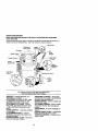
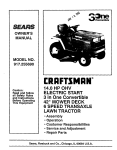
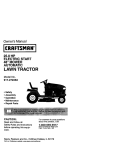
Owner's Manual
ICRRI:¥$1VlRN°
I
20.0 HP
ELECTRIC START
42" MOWER
AUTOMATIC
LAWN TRACTOR
Model No.
917.272442
•
•
•
•
Safety
Assembly
Operation
Maintenance
• Repair Parts
CAUTION:
Read and follow all Safety
Rules and Instructions before
operating this equipment.
For answers to your questions
about this product, Call:
1-800-659-5917
Seers Craftsman Help Line
5 am - 5 pro, Mort - Sat
Sears, Roebuck and Co., Hoffman Estates, II 60179
Visit our Craftsman website:www.sears.com/craftsman
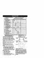
Warranty ............................................... 2
Safety Rules ......................................... 3
Product Specifications.......................... 6
Assembly .............................................. 8
Operation ............................................ 11
Maintenance Schedule ...................... 18
Maintenance ....................................... 18
Service and Adjustments.................... 23
Storage ............................................... 29
Troubleshooting ................................. 30
Repair Parts ........................................ 34
Parts Ordering ..................... Back Cover
LIMITED TWOYEAR WARRANTY ON CRAFTSMAN RIDING EQUIPMENT PARTS
For two (2) years from the date of purchase, if this Craftsman Riding Equipment is
maintained, lubricated and tuned up according to the instructions in the owner's
manual, Sears will repair or replace, free of charge, any parts found to be defective in
material or workmanship. Warranty service is available free of charge by returning your
Craftsman riding equipment to your nearest Sears Service Center. In-home warranty
service is available but a trip charge will apply. This warranty applies only while this
product is in the United States.
This Warranty does not cover:
• Expendable items which become worn during normal use, such as blades, spark
plugs, air cleaners, belts and oil filters.
• Tire replacement or repair caused by punctures from outside objects, such as nails,
thorns, stumps, or glass.
• Repairs necessary because of operator abuse, including but not limited to, damage
caused by towing objects beyond the capability of the riding equipment, impacting
objects that bend the frame or crankshaft, or over speeding the engine.
• Repairs necessary because of operator negligence, including but not limited to,
electrical and mechanical damage caused by improper storage, failure to use the
proper grade and amount of engine oil, failure to keep the deck clear of flammable
debris, or the failure to maintain the equipment according to the instructions contained in the owner's manual.
• Engine (fuel system) cleaning or repairs caused by fuel determined to be contaminated or oxidized (stale). In general, fuel should be used within thirty (30) days of its
purchase date.
• Riding equipment used for commercial or rental purposes. A product is "used for
commercial purpose" if is used for any purpose other than single family household
dwellings or in usage where profit is made.
LIMITED 90 DAY WARRANTY ON BA]-rERY
For ninety (90) days from date of pumhase, if any battery included with this riding
equipment proves defective in matedal or workmanship and our testing determines the
battery will not hold a charge, Sears will replace the battery at no charge. Warranty
service is available free of charge by returning your Craftsman dding equipment to
your nearest Sears Service Center. In-home warranty service is available but a trip
charge will apply. This warranty applies only while this product is in the United States.
TO LOCATE THE NEAREST SEARS SERVICE CENTER OR TO SCHEDULE IN-HOME
WARRANTY SERVICE, SIMPLY CONTACT SEARS AT 1-800-4-MY-HOME
This Warranty gives you specific legal rights, and you may also have other rights which
may vary from state to state.
Sears, Roebuck and Co., D/817 WA, Hoffman Estates, IL 60179
2
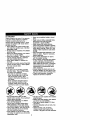
IMPORTANT: This cutt ng machine s capable of amputating hands and feet and
throwing objects. Failure to observe the following safety instructions could result in
serious injury or death.
It. SLOPE OPERATION
I. GENERAL OPERATION
Slopes are ama or factor related to loss-of• Read, understand, and follow all
control and t pover accidents, which can reinstructionsin the manual and on the
sult in severe injury or death. All slopes
machine before starting.
require extra caution. If you cannotbeck up
• Only allow responsible adults, who are
the slope or if you feel uneasy on it, do not
familiar with the instructions, to operate
mow it.
the machine.
DO:
• Clear the area of objects such as rocks,
• Mow up and down slopes, net across.
toys, wire, etc., which cauld be picked
• Remove obstacles such as rocks,tree
up and thrown by the blade.
limbs, etc.
• Be sure the area is dear of other people
Watch for holes, ruts,or bumps. Uneven
before mowing. Stop machine If anyone
terrain could overturn the machine. Tall
enters the area.
grass can hide obstac/es.
: Never
Use slow speed. Choose a low gear so
Do not carry
mow passengers.
in reverse unless absolutely
that you will not have to stop or shift
necessary. Always look down and
while on the slope.
behind before and while becking.
Follow the manufacturer's recommenda• Be aware of the mower discharge
tions for wheel weights or counterdirection and do not point it at anyone.
weights to improve stability.
Do not operate the mower without either
Use extra care with grass catchers or
the entire grass catcher or the guard in
other attachments. These can change
place.
the stability of the machine.
• Slow clownbefore turning.
Keep all movement on the slopes slow
• Never leave a running machine
and gradual. Do not make sudden
unattended. Always turn off blades, set
changes in speed or direction.
perking brake, stop engine, and remove
Avoid starting or stopping on a slope. If
keys before dismounting.
tires lose traction, disengage the blades
• Tum off blades when not mowing.
and proceed slowly straightdown the
• Stop engine before removing grass
slope.
catcher or uncioggiogchute.
DO NOT:
• Mow only in daylight or good artificial
• Do not tum on slopes unlesSnecessary,
light.
• Do not operate the machine while under
and then, rum slowly and gradually
the Influence of alcahol or drugs.
downhill, ff possible.
• Watch for trafficwhen operating near or
• Do notmow near drop-offs, ditches, or
embankments. The mower could
crossing roadways.
• Use extra care when loading or unloadsudoenly turn over if a wheel is over the
ing the machine into a trailer or truck.
edge of a cliffor ditch, or if an edge
• Data indicatesthat operators, age 60
caves in.
• Do notmow on wet grass. Reduced
years and above, are involvedin a large
percentage of tiding
mower-related
traction could cause sil_ng.
injuries. These operators should
• Do not try to stabilize the machine by
evaluate their ability to operate the riding
putting your foot on the ground.
mower safely enough to protect them• Do notuse grass catcher on steep
selves and others from serioos injury.
slopes.
• Keep machine free of grass, leaves or
other debris build-upwhich can touch
hot exhaust / engine parts and bum. Do
not allow the mower deck to plow leaves
or other debris which can cause buildup to occur. Clean any oil or fuel
spillage before operating or storing the
machine. Allow machine to cool before
storage.
Ill. CHILDREN
Tragic accidents can occur if the operator
is not alert to the presence of children.
Children are often attracted to the
machine and the mowing activity. Never
assume that children will remain where
you last saw them.
• Keep children out of the mowing area
and under the watchful care of another
responsible adult.
• Be alert and turn machine off if children
enter the area.
• Before and when backing, look behind
and down for small children.
• Never carry children. They may fall off
and be seriously injured or interfere
with safe machine operation.
• Never allow children to operate the
machine.
• Use extra care when approaching blind
corners, shrubs, trees, or other objects
that may obscure vision.
IV. SERVICE
• Use extra care in handling gasoline
and other fuels. They are flammable
and vapors are explosive.
-Use only an approved container.
-Never remove gas cap or add fuel
with the engine running. Allow
engine to cool before refueling. Do
not smoke.
- Never refuel the machine indoors.
- Never store the machine or fuel
container inside where there is an
open flame, such as a water heater.
• Be sure the area is clear of uther
people before mowing. Stop machine if
anyone enters the area.
• Never carry passengers or children
even with the blades off.
• Do not mow in reverse unless absolutely necessary. Always look down
and behind before and while backing.
• Never carry children. They may fall off
and be seriously injured or interfere
with safe machine operation.
• Keep children out of the mowing area
and under the watchful care of another
responsible adult.
• Never run a machine inside a closed
area.
• Keep nuts and bolts, especially blade
attachment bolts, tight and keep
equipment in good condition.
• Never tamper with safety devices.
Check their proper operation regularly.
• Keep machine free of grass, leaves, or
other debris build-up. Clean oil or fuel
spillage. Allow machine to cool before
storing.
• Stop and inspect the equipment if you
strike an object. Repair, if necessary,
before restarting.
• Never make adjustments or repairs
with the engine running.
• Grass catcher components are subject
to wear, damage, and deterioration,
which could expose moving parts or
allow objects to be thrown. Frequently
check components and replace with
manufacturer's recommended parts,
when necessary.
• Mower blades are sharp and can cut.
Wrap the blade(s) or wear gloves, and
use extra caution when servicing them.
• Check brake operation frequently.
Adjust and service as required.
• Be alert and turn machine off if children
enter the area.
• Before and when backing, look behind
and down for small children.
• Mow up and down slopes (15 ° Max),
not across.
• Remove obstacles such as rooks, tree
limbs, etc.
• Watch for holes, ruts, or bumps.
Uneven terrain could overturn the
machine. Tall grass can hide obstacles.
• Useslow
speed. Choose a low gear so
that you will not have to stop or shift
while on the slope.
• Avoid starting or stopping on a slope. If
tires lose traction, disengage the
blades and proceed slowly straight
down the slope.
• If machine stops while going uphill,
disengage blades, shift into reverse
and back down slowly.
• Do not turn on slopes unless necessary, and then, turn slowly and gradually downhill, if possible.
,_L CAUTION: Tow only the attachments
that are recommended by and comply
with specifications of the manufacturer of
your tractor. Use common sense when
towing. Operate only at the lowest
possible speed when on a slope. Too
heavy of a load, while on a slope, is
dangerous. Tires can lose traction with
the ground and cause you to lose control
of your tractor.
_WARNING:
Engine exhaust, some of
its constituents, and certain vehicle
components contain or emit chemicals
known to the State of California to cause
cancer and birth defects or other reproductive harm.
_l, Look for this symbol to point out
important safety precautions. It means
CAUTIONI!I BECOMEALERT!I! YOUR
SAFETY IS INVOLVED.
_,WARNING:
Battery posts, terminals
and related acoessodes contain lead and
lead compounds, chemicals known to the
State of California to cause cancer and
birth defects or other reproductive harm.
Wash hands after handling.
_, CAUTION: In order to prevent
accidental starting when setting up,
transporting, adjusting or making repairs,
always disconnect spark plug wire and
place wire where it cannot contact spark
plug.
,_ CAUTION: Do not coast down a hill
in neutral, you may lose control of the
tractor.
5
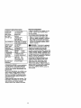
)RODUCT
REPAIR AGREEMENT
SPECIFICATIONS
3ASOLINE
CAPACITY
_,NDTYPE:
_)ILTYPE
'=API-SF-SJ):
)IL CAPACITY:
SPARK PLUG:
SAP: .040")
GROUND
SPEED (MPH):
TIRE
PRESSURE:
CHARGING
SYSTEM:
BATTERY:
BLADE BOLT
TORQUE:
A Repair Agreement is available on this
product. Contact your nearest Sears
store for details.
1.25 GALLONS
UNLEADED
REGULAR
SAE 30
(ABOVE 32°F)
SAE 5W-30
(BELOW 32°F)
W/FILTER: 4.0 PINTS
W/O FILTER:3.75PINTS
CUSTOMER RESPONSIBILITIES
• Read and observe the safety rules.
• Follow a regular schedule in maintaining, caring for and using your tractor.
• Follow the instructions under "Maintenance" and "Storage" sections of this
owner's manual.
CHAMPION
RC12YC
FORWARD: 5.5
REVERSE: 2.4
FRONT:
14 PSI
REAR:
10 PSI
3AMPS BA3qERY
5 AMPS HEADLIGHT
AMP/HR:
28
MIN. CCA: 230
CASE SIZE:U1R
27-35 FT. LBS
_JkWARNING: This tractor Is equipped
with an internal combustion engine and
should not be used on or near any
unimproved forest-covered, brushcovered or grass.covered land unless the
engine's exhaust system is equipped with
a spark arrester meeting applicable local
or state laws (if any). If a spark arraster is
used, it should be maintained in effective
working order by the operator.
In the state of California the above is
required by law (Section 4442 of the
California Public Resoumes Code).
Other states may have similar laws.
Federal laws apply on federal lands. A
spark arrester for the muffler is available
through your nearest Sears service
center (See REPAIR PARTS section of
this manual).
CONGRATULATIONS on your purchase
of a new tractor. It has been designed,
engineered and manufactured to give
you the best possible dependability and
performance.
Should you experience any problem you
cannot easily remedy, please contact a
Sears or other qualified service center.
We have competent, well-trained technicians and the proper tools to service or
repair thistractor.
Please read and retain this manual. The
instructions will enable you to assemble
and maintain your tractor properly.
Always observe the "SAFETY RULES".
6
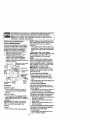
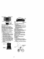
SteeringWheel
Steering
©
Wheel Adapter
t
Steering
Sleeve
Extension
Shaft
teering
(1)5/16-18
Locknut
Steedng
Wheel Insert
©
(1) Hex Bolt
3/8-16 x I
washer
3/8
(1) Hex Bok
5/16-18 x 1-1/4
(1) LargeRat
Washer
(1) Washer
17/32 x 1-3/16 x 12 Gauge
_(1)
Knob
For Future Use
Keys
41
(2) Keys
Video Cassette
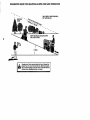
Slope Sheet
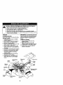
Your new tractor has been assembled at the factory with exception of those parts left
unassambled for shipping purposes. To ensure safe and proper operation of your
tractor all parts and hardware you assemble mast be tightened securely. Use the
correct tools as necessary to insure proper tightness.
TOOLS REQUIRED FOR ASSEMBLY
A socket wrench set will make assembly
easier. Standard wrench sizes you need
are listed below.
6. Assemble large flat washer, 3/8 lock
washer, 3/8 hex bolt and tighten
securely.
7. Snap steering wheel insert into center
of steering wheel.
8. Remove protective materials from
tractor hood and gdll.
IMPORTANT: Check for and remove any
staples in skid that may puncturetires
where tractor is to roll off skid.
(1) 9/16" wrench
(1) Pliers
(2) 1/2" wrench
(1) Utilityknife
(1)Tire pressure gauge
When right or left hand is mentioned in
this manual, it means when you are in the
operating position (seated behind the
steedng wheel).
<_;_
Steedng
Wheel Insert
_Lock
TO REMOVETRACTOR
FROM
CARTON
UNPACK CARTON
1. Remove all accessible loose parts
and parts cartons from carton.
2. Cut, from topto bottom, along lines on
all four comers of carton, and lay
panels flat.
3. Check for any additional loose parts
or cartons and remove.
Hasher
Hex Bolt
Large Flat
Sv_el_
r21ng _Washer
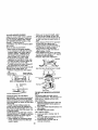
BEFORE REMOVINGTRACTOR
FROM SKID
AI-rACH STEERINGWHEEL
5/16 Locknut_
Lower
Steering _
Shaft_
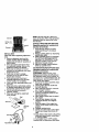
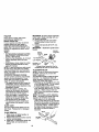
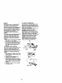
ASSEMBLE EXTENSION SHAFT AND
BOOT
1. Slide extension sh_t onto lower
steering shaft. Align mounting holes
in extension and lower shafts and
install 5/16 hex bolt and Iocknut.
Tighten securely.
IMPORTANT: Tighten bolt and nut
securely to 18-22 ft. Ibs torque.
2. Place tabs of steering boot over tab
slots in dash and push down to
secure.
._5116
Hex Bolt
,"
"_"
'-Q-....
_.
",
_
_)' __-_Tab
; "-- "
/ / Slots
HOWTO SET UPYOURTRACTOR
CHECK BAI"FERY
1. Lift seat pan to raised position and
open battery box door.
NOTE: If this battery is put into service
after month and year indicated on label
(label located between terminals) charge
battery for minimum of one hour at 6-10
amps. (See "BA'I-rERY" in Maintenance
section of this manual for charging
instructions).
INSTALL STEERING WHEEL
3. Position front wheels of the tractor so
they are pointing straight forward.
4. Remove steering wheel adapter from
steering wheel and slide adapter onto
steering shaft extension.
5. Position steering wheel so cross bars
are horizontal (left to right) and slide
inside boot and onto adapter.
8
NOTE: You may now roll or drive your
tractor off the skid. Follow the appropriate
instruction below to remove the tractor
from the skid.
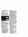
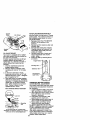
INSTALL SEAT
Adjust seat before tightening adjustment
knob.
1. Remove adjustment knob and flat
washer secudng seat to cardboard
packing and set aside for assembly of
seat to tractor,
2. Pivot seat upward and remove from
the cardboard packing, Remove the
cardboard packing and discard.
3. Place seat on seat pan so head of
shoulder bolt is positioned over large
slotted hole in pan.
4. Push down on seat to engage
shoulder bolt in slot and pull seat
towards rear of tractor.
5. Pivot seat and pan forward and
assemble adjustment knob and flat
washer loosely. Do not tighten.
6. Lower seat into operating position and
sit in seat.
7. Slide seat until a comfortable position
is reached which allows you to press
clatcWbrake pedal all the way down.
8. Get off seat without moving its
adjusted position.
9. Raise seat and tighten adjustment
knob securely.
Seat
Seat Pan_.
Bolt
Flat W__
_
TO ROLLTRACTOR
OFF SKID (See
Operation section for location and
function of controls)
1. Press lift lever plunger and raise
attachment lift lever to its highest
position.
2. Release parking brake by depressing
clutch/Drake pedal.
3. Place freewheel control in freewheeling position to disengage transmission (See "TO TRANSPORT" in the
Operation section of this manual}.
4, Roll tractor forward oft skid,
5. Remove banding holding deflector
shield up against tractor.
TO DRIVETRACTOR
OFF SKID (See
Operation section for location and
function of controls)
_WARNING:
Before starting, read,
understand and follow all instructions in
the Operation section of this manual. Be
sure tractor is in a well-ventilated area, Be
sure the area in front of tractor is clear of
other people and objects.
1. Be sure all the above assembly steps
have been completed.
2. Check engine oil level and fill fuel
tank with gasoline.
3, Place freewheel control in =transmission engaged" position.
4. Sit on seat in operating position,
depress clutch/brake pedal and set
the parking brake,
5. Place motion control lever in neutral
(N) position.
6. Press lift lever plunger and raise
attachment lift lever to its highest
position.
7. Start the engine. After engine has
started, move throttle control to idle
position.
8. Release parking brake.
9. Slowly move the motion control lever
forward and slowly drive tractor off
skid.
10.Apply brake to stop tractor, set parking
brake and place motion control lever
in neutral position.
11 .Turn ignition key to "OFF" position,
Continue with the instructionsthat follow.
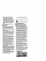
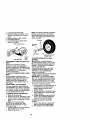
TO CONVERTTO BAGGING OR
CHECKTIRE
PRESSURE
Thetiresonyourtractor
wereoverinflatedDISCHARGING
Simply remove mulcher plate and store in
atthefactory
for shipping purposes.
Correct tire pressure is important for best
cutting performance.
• Reduce tire pressure to PSI shown in
"PRODUCT SPECIFICATIONS" section
of this manual.
CHECK DECK LEVELNESS
For best cutting results, mower housing
should be properly leveled. See "TO
LEVEL MOWER HOUSING" in the
Service and Adjustments section of this
manual.
CHECK FOR PROPER
ALL BELTS
POSITION
OF
a safe place. Your mower is now ready for
discharging or installation of optional
grass catcher accessory.
NOTE: It is not necessary to change
blades. The mulcher blades are de.
signed for discharging and bagging also.
I/CHECKLIST
BEFORE YOU OPERATE AND ENJOY
YOUR NEW TRACTOR, WE WISH TO
ASSURE THAT YOU RECEIVE THE BEST
PERFORMANCE AND SATISFACTION
FROM THIS QUALITY PRODUCT.
PLEASE REVIEWTHE FOLLOWING
CHECKLIST:
/ All assembly instructions have been
completed.
,/No remaining loose parts in carton.
./Battery is propedy prepared and
charged. (Minimum 1 hour at 6 amps).
,/Seat is adjusted comfortably and
tightened securely.
/ All tires are properly inflated. (For
shipping purposes, the tires were
overinflated at the factory).
,/ Be sure mower deck is properly leveled
INSTALL MULCHER PLATE
side-to-side/frent-to-rear for best cutting
(If previously removed)
results. (Tires must be propedy inflated
1. Raise and hold deflector shield in
for leveling).
/ Check mower and drive belts. Be sure
updght position.
2. Place front of mulcher plate over front
they are routed properly around pulleys
of mower deck opening and slide into
and inside all belt keepers.
place, as shown.
,/Check wiring. See that all connections
3. Hook front latch into hole on front of
are still secure and wires are properly
mower deck.
clamped.
4. Hook rear latch into hole on back of
,/' Before driving tractor, be sure freemower deck.
wheel control is in drive position.
_CAUTION:
Do not remove deflector
WHILE LEARNING HOWTO USEYOUR
shield from mower. Raise and hold shield
TRACTOR, PAY EXTRA ATFENTION TO
when attaching malcher plate and allow it
THE FOLLOWING IMPORTANT ITEMS:
to rest on plate while in operation.
,/Engine oil is at proper level.
,/Fuel tank is filled with fresh, clean,
regular unleaded gasoline.
•/ Become familiar with all controls - their
location and function, Operate them
before you start the engine.
/ Be sure brake system is in safe
M_._alCherte
operating condition.
/ It is important to purge the transmission
_Latch
before operating your tractor for the first
time. Follow proper starting and
Hooks
transmission purging instructions (See
"TO START ENGINE" and =PURGE
TRANSMISSION" in the Operation
10 section of this manual).
See the figures that are shown for
replacing motion and mower blade drive
belts in the Service and Adjustments
section of this manual. Verify that the
belts are routed correctly,
CHECK BRAKE SYSTEM
After you learn how to operate your
tractor, check to see that the brake is
properly adjusted. See "TO ADJUST
BRAKE" in the Service and Adjustments
section of this manual.
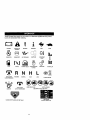
These
symbols
mayappear
onyourtractor
orinliterature
supplied
withtheproduct.
Learn
andunderstand
theirmeaning.
13ATFERY
CAUTION OR
WARNING
REVERSE
ENGINE ON
ENGINE OFF
OIL PRESSURE
LIGHTS ON
OVER TEMP
LIGHT
FUEL
CHOKE
MOWER HEIGHT
PARKING BRAKE
LOCKED
UNLOCKED
A_'FACHMENT
CLUTCH ENGAGED
IGNITION
REVERSE
NEUTRAL
ATTACHMENT
CLUTCH DISENGAGED
FORWARD
FAST
SLOW
!
MOWER LIFT
H
L
®3t
HIGH
LOW
PARKING BRAKE
KEEP AREA CLEAR
SLOPE HAZARDS
(SEE SAFE_'YRULES SECTION)
FREEWHEEL
DANGER, KEEP HANDS AND FEET AWAY
(Automatic
11
Models only)
KNOWYOUR TRACTOR
READ THIS OWNER'S MANUAL AND SAFETY RULES BEFORE OPERATING
YOUR TRACTOR
Compare the illustrationswith your tractor to familiadze yourself with the locations of
vadous controls and adjustments. Save this manual for future reference.
;witch
Attachment
Clutch Lever
Ignition
Ammeter
Choke
Lever
Plunger
Control
Throttle Control
Lift Lever
Clutch/
Brake Pedal
Height
Adjustment
Indicator
Free Wheel
Control
Brake Lever
M_ion
Lever
Our tractors conform to the safety standards of the
Amedcan National Standards Institute.
AMMETER - Indicates charging (+) or
discharging (-) of battery.
ATTACHMENT CLUTCH LEVER - Used
to engage the mower blades, or other
attachments mounted to your tractor.
ATTACHMENT LIFT LEVER - Used to
raise, lower, and adjust the mower deck
or other attachments mounted to your
tractor.
CHOKE CONTROL - Used when starting
a cold engine.
CLUTCH/BRAKE PEDAL - Used for
declutching and braking the tractor and
starting the engine.
MOTION CONTROL LEVER - Selects the
speed and direction of tractor.
FREEWHEEL CONTROL - Disengages
transmission for pushing or slowly towing
the tractor with the engine off.
IGNITION SWITCH - Used for startingand
stopping the engine.
LIFT LEVER PLUNGER - Used to release
attachment lift lever when changing its
position.
LIGHT SWITCH - Turns the headlights on
and off.
PARKING BRAKE LEVER - Locks clutch/
brake pedal into the brake position.
THROTFLE CONTROL- Used to control
engine speed.
12
The operation of any tractor can result in foreign objects thrown into the
eyes, which can result in severe eye damage. Always wear safety
glasses or eye shields while operating your tractor or performing any
adjustments or repairs. We recommend a wide vision safety mask over
spectacles or standard safety glasses.
HOWTO USEYOURTRACTOR
TO SET PARKING BRAKE
Your tractor is equipped with an operator
presence sensing switch. When engine
is running, any attempt by the operator to
leave the seat withoutfirst setting the
parking brake will shut off the engine.
1. Depress clutch/brake pedal into full
"BRAKE" position and hold.
2. Place parking brake lever in "ENGAGED" position and release
pressure from clutcWbrake pedal.
Pedal should remain in "BRAKE"
position. Make sure parking brake will
hold tractor secure.
AttachmentClutchLever
Choke Control
Throttle
Control
Brake
Pedal
Posi_on
.-Parking Brake
=Engaged'
Position
=Brake"
posilJon
Motion
Control
Lever
STOPPING
MOWER BLADES • To stop mower blades,move attachment clutch lever to "DISENGAGED"
position.
GROUND DRIVE • To stop ground ddve, depress clutch/
brake pedal into full "BRAKE" position,
• Move motion control lever to neutral (N)
position.
IMPORTANT: The motion control lever
does not return to neutral (N) position
when the clutch/brake pedal is depressed.
ENGINE • Move throttle control to slow position.
NOTE: Failure to move throttle control to
slow position and allowing engine to idle
before stopping may cause engine to
"backfire".
• Turn ignition key to "OFF" position and
remove key. Always remove key when
leaving tractor to prevent unauthorized
use.
• Never use choke to stop engine.
IMPORTANT: Leaving the ignition switch
in any position other than "OFF" will
cause the battery to be discharged,
(dead).
NOTE: Under certain conditions when
tractor is standing idle with the engine
running, hot engine exhaust gases may
cause "browning" of grass. To eliminate
this possibility, always stop engine when
stopping tractor on grass areas.
_I_CAUTION: Always stop tractor
completely, as described above, before
leaving the operator's position; to empty
grass catcher, etc.
TO USE TH ROI-I'LE CONTROL
Always operate engine at full throttle.
• Operating engine at less than full
throttle reduces the battery charging
rate,
• Full throttle offers the best bagging and
mower performance.
TO USE CHOKE CONTROL
Use choke control whenever you are
starting a cold engine. Do not use to start
a warm engine,
• To engage choke control, pull knob out.
Slowly push knob in to disengage.
TO MOVE FORWARD AND BACKWARD
The direction and speed of movement is
controlled by the motion control lever.
1. Start tractor with motion control lever in
neutral (N) position.
2, Release parking brake and clutch/
brake pedal.
3. Slowly move motion control lever to
desired position.
TO ADJUST MOWER CUI"I1NG HEIGHT
The position of the attachment lift lever
determines the cutting height.
• Grasp lift lever.
• Press plunger with thumb and move
lever to desired position,
13
The cutting height range is approximately 1-1/2 to 4". The heights are
measured from the ground to the blade
tip with the engine not running.
These heights are approximate and may
vary depending upon soil conditions.
height of grass and types of grass being
mowed.
• The average lawn should be cut to
approximately 2-1/2 inches during the
cool season and to over 3 inches
during hot months. For healthier and
better looking lawns, mow often and
after moderate growth.
• For best cutting performance, grass
over 6 inches in height should be
mowed twice. Make the first cut
relatively high; the second to desired
height.
TO ADJUST GAUGE WHEELS
Gauge wheels are properly adjusted
when they are slightly off the ground
when mower is at the desired cutting
height in operating position. Gauge
wheels then keep the deck in proper
position to help prevent scalping in most
terrain conditions.
NOTE: Adjust gauge wheels with tractor
on a flat level surface.
1. Adjust mower to desired cutting height
(See "TO ADJUST MOWER CU'I-FING
HEIGHT" in the Operation section of
this manual).
2. With mower in desired height of cut
position, gauge wheels should be
assembled so they are slightly off the
ground. Instail gauge wheel in
appropriate hole with shoulder bolt,
3/8 washer, and 3/8-16 Iocknut and
tighten securely.
3. Repeat for opposite side installing
gauge wheel in same adjustment
hole.
Gauge
_
_
_Ap_-P"_x
w.o
Mounting
Bracket
Gauge Wheel_
_
_
Bolt
TO OPERATE MOWER
Your tractor is equipped with an operator
presence sensing switch. Any attempt by
the operator to leave the seat with the
engine running and the attachment clutch
engaged will shut off the engine.
1. Select desired height of cut.
2. Start mower blades by engaging
attachment clutch control.
TO STOP MOWER BLADES disengage attachment clutch control.
_]LCAUTION: Do not operate the mower
without either the entire grass catcher, on
mowers so equipped, or the deflector
shield in place.
AttachmentClutch
Lever=Engaged"
AttachemntLift
Position
Lever High
Low
Position
=Disengaged"
Position
"_
Deflector
Shield
TO OPERATE ON HILLS
_kCAUTION: Do not ddve up or down
hills with slopes greater than 15" end do
not drive across any slope.
• Cheese the slowest speed before
starting up or down hills,
• Avoid stopping or changing speed on
hil_s.
• If slowing is necessary, move throttle
control lever to slower position.
• If stopping is absolutely necessary,
push clutch/brake pedal quickly to
brake position and engage parking
brake.
• Move motion control lever to neutral (N)
position.
IMPORTANT: The motion control lever
does not return to neutral (N) position
when the clutch/brake pedal is depressed.
• To restart movement, slowly release
parking brake and clutch/brake pedal.
• Slowly move motion control lever to
slowest setting.
• Make all turns slowly.
TO TRANSPORT
When pushing or towing your tractor, be
sure to disengage transmission by
placing freewheel control in freewheeling
position. Free wheel control is located at
the rear drawbar of tractor.
1. Raise attachment lift to highest
position with attachment lift control.
14
2. Pull freewheel control out and down
into the slot and release so it is held in
the disengaged position.
• Do not push or tow tractor at more than
two (2) MPH.
• To reengage transmission, reverse
above procedure.
NOTE: To protect hood from damage
when transporting your tractor on a truck
or a trailer, be sure hood is closed and
secured to tractor. Use an appropriate
means of tying hood to tractor (rope, cord,
etc.).
TOWING CARTS AND OTHER
ATTACHMENTS
Tow only the attachments that are
recommended by and comply with
specificationsof the manufacturer of your
tractor. Use common sense when towing.
Too heavy of a load, while on a slope, IS
dangerous. Tires can lose traction with
the ground and cause you to lose control
of your tractor.
BEFORE STARTINGTHE
ENGINE
CHECK ENGINE OIL LEVEL
The engine in your tractor has been
shipped, from the factory, already filled
with summer weight oil.
1. Check engine oil with tractor on level
ground.
2. Remove oil fill cap/dipstick and wipe
clean, reiosertthe dipstick and screw
cap tight, wait for a few seconds,
remove and read oil level. If necessary, add oil until "FULL" mark on
dipstick is reached. Do not overfill,
• For coil weather operation you should
change oil for easier starting (See "OIL
VISCOSITY CHART" in the Maintenance section of this manual).
• To change engine oil, see the Maintenance section in this manual.
ADD GASOLINE
• Fill fuel tank. Use fresh, clean, regular
unleaded gasoline with a minimum of
87 octane. (Use of leaded gasoline
will increase carbon and lead oxide
deposits and reduce valve life). Do not
mix oil with gasoline. Purchase fuel in
quantities that can be used within 30
days to assure fuel freshness.
IMPORTANT: When operating in
temperatures below 32°F(O°C), use fresh,
clean winter grade gasoline to help
insure good cold weather starting.
AWARNING:
Expedance indicates that
alcohol blended fuels (called gasohol or
using ethanol or methanol) can attract
moisture which leads to separation and
formation of acids during storage. Acidic
gas can damage the fuel system of an
engine while in storage. To avoid engine
problems, the fuel system should be
emptied before storage of 30 days or
longer. Drainthe gastank, start the
engine and let it run until the fuel lines
and carburetor are empty. Use fresh fuel
next season. See Storage Instructionsfor
additional information. Never use engine
or carburetor cleaner products in the fuel
tank or permanent damage may occur.
_I,CAUTION: Fill to bottom of gas tank
filler neck. Do not overfill. Wipe off any
spilled oil or fuel. Do not store, spill or
use gasoline near an open flame.
TO START ENGINE
When starting the engine for the first time
or if the engine has run out of fuel, it will
take extra crankingtime to move fuel from
the tank to the engine.
f. Be sure freewheel control is in the
transmission engaged position.
2. Sit on seat in operating position,
depress clutch/brake pedal and set
parking brake.
3. Place motion control lever in neutral
(N) position.
4. Move attachment clutch to "DISENGAGED" position.
5. Move throttle control to fast position
6. Pull choke control out for a cold
engine start attempt. For a warm
engine start attempt the choke control
may not be needed.
NOTE: Before starting, read the warm and
cold starting procedures below.
15
7. Insert key into ignition and turn key
clockwise to "START" position and
release key as soon as engine starts.
Do not run starter continuously for
more than fifteen seconds per minute.
If the engine does not start after
several attempts, push choke control
in, walt a few minutes and try again. If
engine still does not start, pull the
choke control out and retry.
WARM WEATHER STARTING (50 ° F and
above)
8. When engine starts, slowly push
choke control in until
the engine
begins to mn smoothly. If the engine
starts to run roughly, pullthe choke
control out slightlyfor a few seconds
and then continue to push the control
in slowly.
* The attachmentsand ground drivecan
now be used. If the engine does not accept
the load, restart the engine and allow it to
warm up for one m_ute using the d_ke
as described above.
COLD WEATHER STARTING (50° F and
below)
8. When engine starts, slowly push
choke control in until the engine
begins to run smoothly. ContinUe to
push the choke control in small steps
allowing the engine to accept small
changes in speed and load, until the
choke contr_ is fully in. If the engine
starts to run roughly, pull the choke
control out slightly for • few seconds
and then continue to push the control
in slowly. This may require an engine
warm-up period from several seconds
to several minutes, depending on the
temperature.
AUTOMATIC TRANSMISSION WARM UP
Before driving the unit in cold weather,
the transmission should be warmed up as
follows:
1. Be sure the tractor is on level ground.
2. Place the motion control lever in
neutral. Release the parking brake
and let the clutch/brake slowly return
to operating position.
3. Allow one minute for transmission to
warm up. This can be done during the
engine warm up period.
• The attachments can be used dudng
the engine warm-up period after the
transmission has been warmed up
and may require the choke control be
pulled out slightly.
NOTE: if at a high altitude (above 3000
feet) or in cold temperatures (below 32 F)
the carburetor fuel mixture may need to
be adjusted for best engine performance.
See "TO ADJUST CARBURETOR" in the
Service and Adjustments section of this
manual.
PURGETRANSMISSION
_iLCAUTION: Never engage or disengage freewheel lever while the engine is
running.
To ensure proper operation and performance, it is recommended that the
transmission be purged before operating
tractor for the first time.
This procedure will remove any trapped
air inside the transmission which may
have developed dudng shipping of your
tractor.
IMPORTANT: Should your transmission
require removal for service or replacement, it should be purged after reinstaltation before operating the tractor.
1. Place tractor safely on level surface
with engine off and parking brake set.
2. Disengage transmission by placing
freewheel control in freewheeling
position (See "TO TRANSPORT" in
this section of manual).
3. Sitting in the tractor seat, start engine.
After the engine is rUnning, move
throttle control to slow position. With
motion control lever in neutral (N)
position, slowly disengage clutch/
brake pedal.
4. Move motion control lever to full
forward position and hold for five (5)
seconds. Move lever to full reverse
position and hold for five (5) seconds.
Repeat this procedure three (3) times.
NOTE; Dudng this procedure there will
be no movement of drive wheels. The air
is being removed from hydraulic ddve
system.
5. Move motion control lever to neutral
(N) position. Shut- off engine and set
parking brake.
6. Engage transmission by placing
freewheel control in driving position
(See "TO TRANSPORT" in this section
of manual).
7. Sitting in the tractor seat, start engine.
After the engine is running, move
thmtUe control to half (1/2) speed. With
motion control lever in neutral (N)
position, slowly disengage clutch/
brake pedal.
16
8. Slowly move motion control lever
forward, after the tractor moves
approximately five (5) feet, slowly
move motion control lever to reverse
position.After the tractor moves
approximately five (5) feet return the
motion control lever to the neutral (N)
position. Repeat this procedure with
the motion control lever three (3)
times.
Your tractor is now purged and now ready
for normal operation.
MCNVlNGTIPS
• Mower should be properly leveled for
best mowing performance. See "TO
LEVEL MOWER HOUSING" in the
Service and Adjustments section of this
manual.
• The left hand side of mower should be
used for trimming.
• Drive so that clippings are discharged
onto the area that has been cut. Rave
the cut area to the right of the tractor.
This will result in a more even distribution of clippings and more uniform
cutting.
• When mowing large areas, start by
turning to the dght so that clippings will
discharge away from shrubs, fences,
driveways, etc. After one or two
rounds, mow in the opposite direction
making left hand turns until finished.
• If grass is extremely tall, it should be
mowed twice to reduce load and
possible fire hazard from dried clippings. Make first cut relatively high; the
second to the desired height.
• Do not mow grass when it is wet. Wet
grass will plug mower and leave
undesirable clumps. Allow grass to dry
before mowing.
• Always operate engine at full throttle
when mowing to assure better mowing
performance and proper discharge of
material. Regulate ground speed by
selecting a low enough gear to give the
mower cutting performance as well as
the quality of cut desired.
• When operating attachments, select a
ground speed that will suit the terrain
and give best performance of the
attachment being used.
MULCHING MOWINGTIPS
IMPORTANT: For best performance,
keep mower housing free of built-up
grass and trash. Clean after each use.
• The special mulching blade will racut
the grass clippings many times and
reduce them in size so that as they fall
onto the lawn they will disperse into the
grass and not be noticed. Also, the
mulched grass will biodegrade quickly
to provide nutrientsfor the lawn.
Always mulch with your highest engine
(blade) speed as this will provide the
best recutting action of the blades.
• Avoid cutting your lawn when it is wet.
Wet grass tends to form clumps and
interferes with the mulching action.
The best time to mow your lawn is the
early afternoon. At this time the grass
has dded and the newly cut area will
not be exposed to the direct sun.
• For best results, adjust the mower
cutting height so that the mower cuts off
only the top one-third of the grass
blades. For extremely heavy mulching,
reduce your width of cut on each pass
and mow slowly.
• Certain types of grass and grass
conditions may require that an area be
mulched a second time to completely
hide the clippings. When doing a
second cut, mow across or perpendicular to the first cut path.
• Change your cutting pattern from week
to week. Mow northto south one week
then change to east to west the next
week, This will help prevent matting
and graining of the lawn.
,
17
.
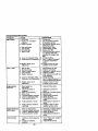
MAINTENANCE SCHEDULE
FILL IN DATES
AS YOU COMPLETE
REGULAR SERVICE
Ch_
ERVICE
StokeOporatio_
f_
lJ
Ch_ TileProssur*
I/
k/
ChedcOperator
Intodock
S_tems Presenceand
!(I_
Ch,e,l_,L=,, En,_,r=
IV'
Sharpen)Rep_co
I
Mo'_,_r Blados
v',
DATES
v'
11_4
Lubdcatlon Chart
_
I_
Check Batlory Ll_gl
C_an Battery and Termll_als
i1##
Chock Tmn r_xle Cooling
{1_
Adjust Bbde I_lt (s) Ti*nslon
_IUst
I_s
Motin_l Drive Belt(s) T_slon
Check Engine Oil Lever
I II_s
_#1
I_
Change Engkm Oil
_,!
Clean Air Filter
_1_
Clean Air Screen
_2
I_spwc_ Muffler/Spark Armster
i_ #
J_
RepTaceOil Filter Ill equipped)
i _z
Clean Engine Cooling Fil_s
j _1_2
R_ptao,
spark
Pk,g
II,/
Replace Air Filter Paper Cartridge
Ik/=
Rop_ce FUOf Filter
12 •
3 4 -
(_IN_
r_ul O_ _€:,1_ o_mtt_
Lt_ll II hNvy Io6d _" in tllgh L'_tt_t
S_lo_ mo_ OP,_ _
oper_
kt dir_ or dusty =_rK_ions.
If lquinped vJJh _ flo_, oha_ge =I every 50 bout.
P,_e
I:_dl_ mo_ Orbit wh_ mo_g
in _oy
SO1.
GENERAL
_l_p_lbr
5 + If io_ipp_ ,dlh _iuCaBi
_-/=lr_
6. Not p=qulred If e_uipp4d w_h m_lle_anoz.fn_
b4zttzry.
7 - TIg_
ft_t _M p_0t _ to 35 ft _
mlr, ill_m
Do_X =,*,e,_ght_.
RECOMMENDATIONS
The warranty on this tractor does not
cover items that have been subjected to
operator abuse or negligence. To receive
full value from the warranty, operator must
maintain tractor as instructed in this
manual.
Some adjustments will need to be made
periodicany to properly maintain your
tractor.
All adjustments in the Service and
Adjustments section of this manual
should be checked at least once each
season.
• Once a year you should replace the
spark plug, clean or replace air filter,
and check blades and belts for wear. A
new spark plug and clean air filter
assure proper air-fuel mixture and help
your engine run better and last longer.
BEFORE EACH USE
1. Check engine oil level.
2. Check brake operation.
3. Check tire pressure.
4. Check operator presence and
interlock systems for proper operation.
5. Check for loose fasteners.
_
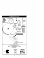
LUBRICATION CHART
_ Spindle_
_--_'_1_
_ Spindle
Zerk
_'_:JI
!_..._, '
_t,,_
::=:: _Zerk
(_Front Wheel,_.
Bearing
Zerk /F_._/
®Engine .
i'
._ ..... . _-_Fr°ntL-_,___
"_==_==
_"_ Bead_Whze_/
--_
'-.....
_'General PurposeGrease
_'Refer to Maintenance "Engine" Sec_on
IMPORTANT: Do not oil or grease the
pivot points which have special nylon
bearings. Viscous lubricants will attract
dust and dirt that will shorten the life of
the seff-lubricatin()bearings. If you feel
they must be lubricated, use only a dry,
powdered graphite type lubricant
sparingly.
18
TRACTOR
Always observe safety rules when
pedorrning any maintenance.
BRAKE OPERATION
If tractor requires more than six (6) feet
stopping distance at high speed in
highest gear, then brake must be adjusted. (See "TO ADJUST BRAKE" in the
Service and Adjustments section of this
manual).
TIRES
• Maintain proper air pressure in all tires
(See "PRODUCT SPECIFICATIONS"
section of this manual).
• Keep tires free of gasoline, oil, or insect
control chemicals which can harm
rubber.
• Avoid stumps, stones, deep ruts, sharp
objects and other hazards that may
cause tire damage.
NOTE: To seal tire punctures and prevent
flat tires due to slow leaks, tire sealant
may be purchased from your local parts
dealer. Tire sealant also prevents tire dry
rot and corrosion.
OPERATOR PRESENCE SYSTEM
Be sure operator presence and interlock
systems are working properly. If your
tractor does not function as described,
repair the problem immediately.
• The engine should not start unless the
clutch/brake pedal is fully depressed
and attachement clutch control is in the
disengaged position.
• When the engine is running, any
attempt by the operator to leave the
seat withoutfirst setting the parking
brake should shut off the engine.
• When the engine is running and the
attachment clutch is engaged, any
attempt by the operator to leave the
seat should shut off the engine.
• The attachment clutch should never
operate unless the operator is in the
seat.
BLADE CARE
For best results mower blades must be
kept sharp. Replace bent or damaged
blades.
IMPORTANT: To ensure proper assembly,
center hole in blade must align with star
on mandrel assembly.
4. Reassemble hex bolt, lock washer
and flat washer in exact order as
shown.
5. Tighten bolt securely (27-35 Ft. Lbs.
torque).
IMPORTANT: Blade bolt is grade 8 heat
treated.
Mandrel
Trailing
Assembly
Rat
"A Grade 8 HeatTreatedBoltCan Be
Iden1_edBy Six LinesOn The BoltHead
TO SHARPEN BLADE
NOTE: We do not recommend sharpening blade - but if you do, be sure the
blade is balanced.
Care should be taken to keep the blade
balanced. An unbalanced blade will
cause excessive vibration and eventual
damage to mower and engine.
• The blade can be sharpened with a file
or on a grinding wheel. Do not attempt
to sharpen while on the mower.
• To check blade balance, you will need
a 5/8" diameter steel bolt, pin, or a cone
balancer. (When using a cone balancer, follow the instructions supplied
with balanser.)
NOTE; Do not use a nail for balancing
blade. The lobes of the center hole may
appear to be centered, but are not.
• Slide blade on to an unthreaded
portion of the steel bolt or pin and hold
the bolt or pin parallel with the ground.
If blade is balanced, it should remain in
a horizontal position. If either end of
the blade moves downward, sharpen
the heavy end until the blade is
balanced.
BLADE REMOVAL
1. Raise mower to highest position to
allow access to blades.
2. Remove hex bolt, lock washer and flat
washer securing blade.
3. Install new or resharpened blade with
trailing edge up towards deck as
shown.
._Bladecenter/
orP,
19
/
BA'rFERY
Your tractor has a baftery charging system
which is sufficientfor normal use. However, periodic charging of the battery with
an automotive charger will extend its life.
• Keep battery and terminals clean.
• Keep battery bolts tight.
• Keep small vent holes open.
• Recharge at 6-10 amperes for 1 hour.
NOTE: The original equipment battery on
your tractor is maintenance free. Do not
attempt to open or remove caps or covers.
Adding or checking level of electrolyte is
not necessary.
TO CLEAN BATTERY AND TERMINALS
Corrosion and dirt on the battery and
terminals can cause the battery to "leak"
power.
1. Open battery box door.
2. Disconnect BLACK battery cable first
then RED battery cable and remove
battery from tractor.
3. Rinse the battery with plain water and
dry.
4. Clean terminals and battery cable
ends with wire brush until bright.
5. Coat terminals with grease or petroleum jelly.
6. Reinstall battery (See "REPLACING
BA'I-rERY" in the SERVICE AND
ADJUSTMENTS section of this
manual).
V-BELTS
Check V-pelts for deterioration and wear
after 100 hours of operation and replace
if necessary.The belts are not adjustable.
Replace belts if they begin to slip from
wear.
TRANSAXLE PUMP FLUID
The transaxle was sealed at the factory
and fluid maintenance is not required for
the life of the transaxle. Should the
transaxle ever leak or require servicing,
contact your nearest authorized service
center/department.
ENGINE
LUBRICATION
Only use high quality detergent oil rated
with API service classificationSF-SJ,
Select the oil's SAE vls(_alty grade
accordingto your expected operating
temperature.
SAE vtsCOSITy GRADES
NOTE: Although multi-viscosity oils
(5W30, 10W30 etc.) improve startingin
cold weather, these multi-viscosity oils will
result in increased oil consumptionwhen
used above 32°F. Chac_ your engine oil
level more frequently to avoid possible
engine damage from running low on oil.
Change the oil after every 50 hoursof
operation or at leastonce a year if the
tractor is not used for 50 hoursin one year.
Check the crankcase oil level before
startingthe engine and after each eight (8)
hours of operation. Tighten oil itll cap/
dipsticksecurelyeach time you check the
oil level.
TO CHANGE ENGINE OIL
Determine temperature range expected
before oil change. All oil must meet API
TRANSAXLE COOLING
service classification SF-SJ.
The transmission fan and cooling fins
• Be sure tractor is on level surface.
should be kept clean to assure proper
• Oil will drain more freely when warm.
cooling.
• Catch oil in a suitable container.
Do not attempt to clean fan or transmis1. Remove oil fill cap/dipstick. Be careful
sion while engine is running or while the
not to allow dirt to enter the engine
transmission is hot. To prevent possible
when changing oil,
damage to seals, do not use high
2. Remove cap from end of drain valve
pressure water or steam to clean
and install the drain tube onto the
transaxle.
fitting.
• Inspect cooling fan to be sure fan
3. Unlock drain valve by pushing inward
blades ere intact and clean.
slightly and tuming counterclockwise.
• Inspect coolingfins for dirt, grass
4. To open, pull out on the drain valve.
clippings and other materials. To
5. After oil has drained completely, close
prevent damage to seals, do not use
and lock the drain valve by pushing
compressed air or high pressure
inward and taming clockwise until the
sprayer to clean cooling fins.
pin is in the locked position as shown.
6.
Remove the drain tube and replace
the cap onto to the end of the drain
valve.
2O
7. Refillengine
withoilthrough
oilfill
dipstick
tube.Pourslowly.Donot
overfill.Forapproximate
capacity
see
=PRODUCT SPECIFICATIONS"
section of this manual,
8. Use gauge on oil fill cap/dipstick for
checking level. Be sure dipstick cap is
tightened securely for accurate
reading. Keep oil at "FULL" line on
dipstick.
Oil DrainValve
Closed _
P_on
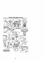
TO SERVICE PRE-CLEANER
2. Wash it in liquid detergent and water.
3. Squeeze it dry in a clean cloth.
4. Saturate it in engine oil, Wrap it in
clean, absorbent cloth and squeeze to
remove excess oil.
NOTE: If very dirty or damaged, replace
pre-cleaner.
TO SERVICE CARTRIDGE
5. Clean cartridge by tapping gently on
flat surface. If very dirty or damaged,
replace cartridge.
6. Reinstall precleaner cartridge, cover
and secure with knobs.
IMPORTANT: Petroleum solvents, such
as kerosene, are not to be used to clean
the cartridge. They may cause deterioration of the carfddge. Do not oil cartridge.
Do not use pressudzed air to clean or dry
cartddge.
Cap
Drain Tube
CLEAN AIR SCREEN
Air screen must be kept free of dirt and
chaff to prevent engine damage from
overheating. Clean with a wire brush or
compressed air to remove dirt and
stubborn dried gum fibers.
CLEAN AIR INTAKE/COOLING AREAS
To insure proper cooling, make sure the
grass screen, cooling fins, and other
external surfaces of the engine are kept
clean at all times.
Every 100 hours of operation (more often
under extremely dusty, dirty conditions),
remove the blower housing and other
cooling shrouds. Clean the cooling fins
and external surfaces as necessary. Make
sure the cooling shrouds are reinstalled.
NOTE: Operating the engine with a
blocked grass screen, dirty or plugged
cooling fins, and/or cooling shrouds
removed will cause engine damage due
to overheating.
AIR FILTER
ENGINE OIL FILTER
Replace the engine oil filter every season
or every other oil change if the tractor is
used more than 100 hours in one year.
MUFFLER
Inspect and replace corroded muffler and
spark arrester (if equipped) as it could
create a fire hazard and/or damage,
SPARK PLUGS
Replace spark plugs at the beginning of
each mowing season or after every 100
hours of operation, whichever occurs first.
Spark plug type and gap setting are
shown in "PRODUCT SPECIFICATIONS"
section of this manual.
Your engine will not run properly using a
dirty air rifler. Clean the foam pre-cleaner
after every 25 hours of operation or every
season. Service paper cartridge every
100 hoursof operation or every season,
whichever occurs first.
Service air cleaner more often under
dusty conditions.
1. Remove knobs and cover.
21
IN-LINE FUEL FILTER
The fuel filter should be replaced once
each season. If fuel filter becomes
clogged, obstructing fuel flow to carburetor, replacement is required.
1. With engine cool, remove filter and
plug fuel line sections.
2. Place new fuel filter in position in fuel
line with arrow pointing towards
carburetor.
3. Be sure there are no fuel line leaks
and clamps are propedy positioned,
4. Immediately wipe up any spilled
gasoline.
CLEANING
• Clean engine, battery, seat, finish, etc.
of all foreign matter.
• Keep finished surfaces and wheels free
of all gasoline, oil, etc.
• Protect painted surfaces with automotive type wax.
We do not recommend using a garden
hose to clean your tractor unless the
electrical system, muffler,air filter and
carburetor are covered to keep water out.
Water in engine can result in a shortened
engine life.
C_amp
Fuel Filter_
22
_
CAUTION: BEFORE PERFORMING ANY SERVICE OR ADJUSTMENTS:
1, Depress clutch/brake pedal fully and set parking brake,
2. Place motion control lever in neutral (N) position.
3. Place attachment clutch in "DISENGAGED" position.
4. Turn ignition key "OFF" and remove key.
5. Make sure the blades and all moving parts have completely stopped.
6. Disconnect spark plug wire from spark plug and place wire where it cannot
come in contact with plug.
TRACTOR
TO REMOVE MOWER
Mower will be easier to remove from the
dght side of tractor.
1. Place attachment clutch in =DISENGAGED" position.
2. Move attachment lift lever forward to
lower mower to its lowest position.
3. Roll belt off engine pulley.
4. Remove small retainer spdng, and lift
clutch spdng off pulley bolt.
5. Remove large retainer spring, slide
collar off and push housing guide out
of bracket.
6. Disconnect anti-swaybar from chassis
bracket by removing retainer spdng.
7. Disconnect suspension arms from
rear deck brackets by removing
retainer spdngs.
8. Disconnect front links from deck by
removing retainer springs.
9. Raise lift lever to raise suspension
arms. Slide mower out from under
tractor.
IMPORTANT: If an attachment other than
the mower deck is to be mounted on the
tractor, remove the front links and hook
the clutch spdng Into square hole in
frame.
TO INSTALL MOWER
1. Raise attachment lift lever to its
highest position.
2. Slide mower under tractor with
deflector shield to dght side of tractor.
3. Lower lift lever to its lowest position.
4. Install mower in reverse order of
removal instructions,
Small Retainer
Clutch
Pulley
Retainer
Spnng
Anti-Sway
_prings
(Both Sides)
Collar_
Housing
Guide
s Retainer
Spring
Bracket
23
TO LEVEL MOWER HOUSING
Adjust the mower while tractor is parked
on level ground or driveway. Make sure
tires are properly inflated (See =PRODUCT SPECIFICATIONS" section of this
manual). If tires are over or
underinflated, you will not properly adjust
your mower.
SIDE-TO-SIDE ADJUSTMENT
• Raise mower to its highest position.
• At the midpoint of both sides of mower,
measure height from bottom edge of
mower to ground. Distance "A" on
both sides of mower should be the
same or within 1/4" of each other.
• If adjustment is necessary, make
adjustment on one side of mower only.
• To raise one side of mower, tighten lift
link adjustment nut on that side.
, To lower one side of mower, loosen lift
link adjustment nut on that side.
NOTE:Each full turn of adjustment nut will
change mower height about 1/8".
• Recheck measurements after adjusting.
Bottomedge of
Bottomedge of
rnowe_
• If links are not equal in length, adjust
one link to same length as other link.
• To lower front of mower loosen nut "E"
on both front links an equal number of
turns.
• When distance "D" is 1/8" to 1/2" lower
at front than rear, tighten nuts "F"
against trunnion on both front links.
• To raise front of mower, loosen nut =F"
from trunnion on both front links.
Tighten nut "E" on both front links an
equal number of turns.
• When distance "D" is 1/8" to 1/2" lower
at front than rear, tighten nut "F" against
trunnion on both front links.
• Recheck side-to-side adjustment.
_=
.
..
Mandrel
BothFront Unks Shouldbe Equalin Length
gr°und
G uod,,oo
V-JT
Nut =_
Nm "E_
Suspension
Tmnnion_
Fmnt Links
Lift Link Ad_
FRONT-TO-BACK ADJUSTMENT
IMPORTANT: Deck must be level side-to
side. If the following front-to-back adjustment is necessary, be sure to adjust both
front links equally so mower will stay level
side-to-side.
To obtain the best cutting results,the
mower housing should be adjusted so
that the front is approximately 1/8" to 1/2"
lower than the rear when the mower is in
its highest position.
Check adjustment on right side of tractor.
Measure distance "D" directly in front and
behind the mandrel at bottom edge of
mower housing as shown.
• Before making any necessary adjustments, check that both front linksare
equal in length.
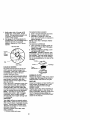
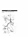
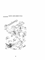
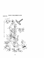
TO REPLACE MOWER BLADE DRIVE
BELT
The mower blade drive belt may be
replaced without tools. Park the tractor on
level surface, Engage parking brake.
BELT REMOVAL 1. Remove mower from tractor (See =TO
REMOVE MOWER" in this section of
this manual).
2. Work belt off both mandrel pulleys and
idler pulleys.
3. Pull belt away from mower.
BELT INSTALLATION 4. Install new belt in reverse order of
removal.
5. Make sure belt is in all pulley grooves
and inside all belt guides.
8. Install mower in reverse order of
removal instructions,
24
Mandrel
Pulley
TO ADJUST BRAKE
Your tractor is equipped with an adjustable brake system which is mounted on
the side of the transaxle.
If tractor requires more than six (6) feet
stopping distance at high speed in
highest gear on a level dry concrete or
paved sudaca, then brake must be
adjusted.
1. Depress clutch/brake pedal and
engage parking brake.
2. Measure distance between brake
operating arm and nut "A" on brake
rod.
3. If distance is other than 1-9/16",
loosen jam nut and turn nut "A" until
distance becomes 1-9/16". Retighten
jam nut against nut "A".
4. Road test tractor for proper stopping
distance as stated above. Readjust if
necessary. If stopping distance is still
greater than six (6) feet in highest
gear, further maintenance is necessary. Contact a Sears or other
qualified service center.
WITH PARKING BRAKE "ENGAGED"
- Operating
Arm
Do not touch this nut. ff further brake
adjustment is necessary contact your nearest
authorized service center/department.
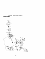
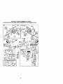
TO REPLACE MOTION DRIVE BELT
Park the tractor on level surface. Engage
parking brake. For assistance, there is a
belt installation guide decal on bottom
side of left footrest.
1. Remove mower (See "ro REMOVE
MOWER" in this section of this
manual.)
2. Remove bell from stationary idler and
clutching idler.
3. Pull belt slack toward rear of tractor.
Carefully remove belt upwards from
transmission input pulley and over
cooling fan blades.
4. Pull belt toward front of tractor and
remove downward from around
engine pulley.
5. Install new bell by reversing above
procedure.
Eng
Clutching
Stationar
Transmission
Input Pulley
TRANSAXLE MOTION CONTROL
LEVER NEUTRAL ADJUSTMENT
The motion control lever has been preset
at the factory and adjustment should not
be necessary.
1. Loosen adjustment bolt in front of the
right rear wheel, and lightly tighten.
2. Start engine and move motion control
lever until tractor does not move
forward or backward.
3. Hold motion control lever in that
position and turn engine off.
4. While holding motion control lever in
place, loosen the adjustment bolt.
5. Move motion control lever to the
neutral (N) (lock gate) position.
6. Tighten adjustment bolt securely.
NOTE: If additional clearance is needed
to get to adjustment bolt, move mower
deck height to the lowest position.
After above adjustment is made, if the
tractor still creeps forward or backward
while motion control lever is in neutral
25Position, follow these steps:
1. Loosen the
adjustment bolt.
2. Move the motion control lever 1/4 to
1/2 inch in the direction it is trying to
creep.
3. Tighten adjustment bolt securely.
4. Start engine and test.
5. If tractor still creeps, repeat above
steps until satisfied.
Motion Control Lever
NOTE: To seal tire punctures and prevent
flat tires due to slow leaks, tire sealant
may be purchased from your local parts
dealer. Tire sealant also prevents tire dry
rot and corrosion.
Retaining
Ring ___
Neutral
Lock
Gate
TRANSMISSION REMOVAUREPLACEVENT
Should your transmission require
removal for service or replacement, it
should be purged after reinstallation and
before operating the tractor. See "PURGE
TRANSMISSION" in the Operation
section of this manual.
TO ADJUST STEERING WHEEL ALIGNVENT
If steering wheel crossbars are not
horizontal (left to right) when wheels are
positioned straight forward, remove
steedng wheel and reassemble per
instructionsin the Assembly section of
this manual.
FRONT WHEEL TOE-IN/CAMBER
The front wheel toe-in and camber are
not adjustable on your tractor. If damage
has occurredto affect the front wheel toein or camber, contact your nearest Sears
or other qualified service center.
TO REMOVE WHEEL FOR REPAIRS
1. Block up axle securely.
2. Remove axle cover, retaining ring and
washers to allow wheel removal (rear
wheel contains a square key - Do not
lose).
3. Repair tire and reassemble.
NOTE: On rear wheels only: align
grooves in rear wheel hub and axle.
Insert square key.
4. Replace washers and snap retaining
ring securely in axle groove.
5. Replace axle cover.
\Square
Key (Rear
Wheel Only)
TO START ENGINE WITH A WEAK
BA'rrERY
CAUTION: Lead-acid batteries
generate explosive gases, Keep sparks,
flame and smoking materials away from
batteries. Always wear eye protection
when around batteries.
If your battery is too weak to startthe
engine, it should be recharged, (See
"BATI'ERY" in the MAINTENANCE
section of this manual),
If =jumper cables" are used for emergency
starting, follow this procedure:
IMPORTANT: Yourtractor is equipped
with a 12 volt negative grounded system.
The other vehical must also be a 12 volt
negative grounded system. Do not use
your tractor battery to startother vehicles.
TO ATTACH JUMPER CABLES 1. Connect each end of the RED cable to
the POSITIVE (+) terminal of each
battery, taking care not to short
against chassis.
2. Connect one end of the BLACK cable
to the NEGATIVE (-) terminal of fully
charged battery.
3. Connect the other end of the SLACK
cable to good CHASSIS GROUND,
away from fuel tank and battery.
TO REMOVE CABLES, REVERSE
ORDER 1. BLACK cable first from chassis and
then from the fully charged battery,
2. RED cable last from both batteries.
26
positive T
bTerminal
Keps Nut.,_
" Cables
REPLACING BA'FrERY
_.CAU'rlQN: ..Do.notshort ba.ttery
rermmats oy altowmg a wrencn or any
other object to contact both terminals at
the same time. Before connecting battery,
remove metal bracelets, wristwatch
bands, rings, etc.
Positiveterminal must be connected first
to prevent sparking from accidental
grounding.
1, Lift seat pan to raised position and
open battery box door.
2. Disconnect BLACK battery cable first
then RED battery cable and carefully
remove battery from tractor.
3. Install new battery with terminals in
same position as old battery,
4. First connect RED battery cable to
positive (+) terminal with hex bolt and
keps nut as shown. Tighten securely.
5. Connect BLACK grounding cable to
negative (o) terminal with remaining
hex bolt and keps nut. Tighten
securely.
6. Close battery box door,
positive (Red)
Cable
Hex
Negative
(Black)Cable
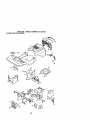
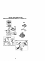
TO REPLACE HEADLIGHT BULB
1. Raise hood.
2. Pull bulb holder out of the hole in the
backside of the gdll.
3. Replace bulb in holder and push bulb
holder securely back into the hole in
the backside of the grill.
4. Close hood.
INTERLOCKS AND RELAYS
Loose or damaged widng may cause your
tractor to run poody,stop running, or
prevent it from starting.
• Check widng. See electrical widng
diagram in the Repair Parts section.
TO REPLACE FUSE
Replace with 20 amp automotive.type
plug-infuse. The fuse holder is located
behind the dash.
TO REMOVE HOOD AND GRILL
ASSEMBLY
1. Raise hood.
2. Unsnap headlight wire connector.
3. Stand in front of tractor. Grasp hood at
sides, tilt toward engine and lift off of
tractor.
4. To replace, reverse above procedure.
Headlight Wire
Connector
Batter
Box Door
27
ENGINE
Maintenance, repair, or replacement of
the emission control devices and systems, which are being done at the
customers expense, may be performed by
any non-road engine repair establishment or individual. Warranty repairs must
be performed by an authorized engine
manufacturer's service outlet.
TO ADJUST THROTTLE CONTROL
CABLE
The throttle control has been preset at the
factory and adjustment should not be
necessary. Check adjustment as described below before loosening cable. If
adjustment is necessary, proceed as
follows:
1. With engine not running, move throttle
control lever to fast position.
2. Check that swivel is against stop. If it is
not, loosen cable clamp screw and
pull cable back until swivel is against
stop. Tighten cable clamp screw
securely.
TO ADJUST CHOKE CONTROL
The choke control has been preset at the
factory and adjustment should not be
necessary. Check adjustment as described below before loosening cable. If
adjustment is necessary, proceed as
follows:
1. With engine not running, move choke
control (located on dash panel) to full
choke position.
2. Loosen knob and remove cover
assembly from air cleaner.
3. Choke should be closed. If it is not,
loosen casing clamp screw and move
choke cable until choke is completely
closed. Tighten casing clamp screw
securely.
4. Replace air cleaner cover assembly
and tighten knob.
TO ADJUST CARBURETOR
Your carburetor is not adjustable. If your
engine does not operate propedy due to
suspected carburetor problems, take your
tractor to an authorized service center for
repair and/or adjustment.
High speed stop is factory adjusted. Do
not adjust - damage may result.
IMPORTANT: Never tamper with the
engine governor, which is factory set for
proper engine speed. Overspeeding the
engine above the factory high speed
setting can be dangerous. If you think the
engine-governed high speed needs
adjusting, contact a Sears or other
qualified service center,, which has
proper equipment and experience to
make any necessary adjustments.
Screw
Clamp S
28
I_
Immediately prepare your tractor for
storage at the end of the season or if the
tractor will not be used for 30 days or
more.
CAUTION: Never store the tractor with
gasoline in the tank inside a building
where fumes may reach an open flame or
spark, Allow the engine to cool before
storing in any enclosure.
TRACTOR
Remove mower from tractor for winter
storage. When mower is to be stored for
a period of time, clean it thoroughly,
remove all dirt, grease, leaves, etc. Store
in a clean, dry area.
1. Clean entire tractor (See "CLEANING"
in the Maintenance section of this
manual).
2. Inspect and replace belts, if necessary
(See belt replacement instructions in
the Service and Adjustments section
of this manual).
3. Lubricate as shown in the Maintenance section of this manual
4, Be surethat all nuts, bolts and screws
are securely fastened. Inspect moving
parts for damage, breakage and wear.
Replace if necessary.
5. Touch up all rested or chipped paint
surfaces; sand lightly before painting.
BATTERY
• Fully charge the battery for storage.
• After a period of time in storage, battery
may require recharging.
• To help prevent corrosion and power
leakage during long pedods of storage,
battery cables should be disconnected
and battery cleaned thoroughly (see
=TO CLEAN BATTERY AND TERMINALS" in the Maintenance section of
this manual).
• After cleaning, leave cables disconnected and place cables where they
cannot come in contact with battery
terminals.
• If battery is removed from tractor for
storage, do not store battery directly on
concrete or damp surfaces.
ENGINE
FUEL SYSTEM
IMPORTANT: It is impertant to prevent
gum deposites from forming in essential
fuel system parts such as carburetor,fuel
hose, or tank during storage.
Also, experiance indicates that alcohol
blended fuels (called gasohol or using
ethanol or methanol) can attract moisture
which leads to separation and formation
of acids during storage. Acidic gas can
damage the fuel system of and engine
while in storage.
1. Drain the fuel tank.
2. Start the engine and let it run until the
fuel lines and carburetor are empty.
• Never use engine or carburetor cleaner
products in the fuel tank or permanent
damage may occur.
• Use fresh fuel next season.
NOTE: Fuel stabilizer is an acceptable
alternative in minimizing the formation of
fuel gum deposits during storage. Add
stabilizer to gasoline in fuel tank or
storage container. Always follow the mix
ratio found on stabilizer container. Run
engine at least 10 minutes after adding
stabilizer to allow the stabilizer to reach
the carburetor. Do not drain the gas tank
and carburetor if using fuel stabilizer.
ENGINE OIL
Drain oil (with engine warm) and replace
with clean engine oil. (See "ENGINE" in
the Maintenance section of this manual).
CYLINDER(S)
1. Remove spark plug(s).
2. Pour one ounce of oil through spark
plug hole(s) into cylinder(s).
3. Turn ignition key to "START" position
for a few seconds to distribute oil.
4. Replace with new spark plug(s).
OTHER
• Do not store gasoline from one season
to another.
• Replace your gasoline can if your can
starts to rust. Rust and/or dirt in your
gasoline will cause problems.
• If possible, store your tractor indoors
and cover it to give protection from dust
and dirt.
• Cover your tractor with a suitable
protectivecover that does not retain
moisture. Do not use plastic. Plastic
cannot breathe which allows condensation to form and will cause your
tractor to rust.
IMPORTANT: Never cover tractor while
engine and exhaust areas are still warm.
29
TROUBLESHOOTING
CHART
CORREC'I1ON
1. Fill fuel tank.
2. See=TO START ENGINE"
in Operation section.
3. Wait several minutes before
attempting to start.
4. Bad spark plug.
4. Replace spark plug.
5. Dirty air filter.
5. Clean/replace air filter.
6. Dirty fuel filter.
6. Replace fuel filter.
7. Drain fuel tank and carbure7. Water in fuel.
tor, refilltank with fresh
gasoline and replace fusl
filter.
8. Loose or damaged wiring.
8. Check all wiring.
9. Carburetor out of adjustment. 9. See "To Adjust Carburetor"
in Service Adjustments
section.
10.Contact a Sears or other
10.Engine valves out of
adjustment.
qualified service center.
PROBLEM
Will n_ start
CAUSE
1. Out ot fuel.
2. Engine not "CHOKED"
properly.
3. Engine flooded.
Hard to start
1.
2.
3.
4.
5.
Engine will not
[urn over
1. Brake pedal not
depressed
2. Attachment clutch is
engaged.
3. Weak or dead battery.
4. Blown fuse.
5. Corroded battery terminals.
6. Loose or damaged wiring.
7. Faulty ignition switch.
Dirty air fifier.
Bad spark plug.
Weak or dead battery.
Dirty fuel filter.
Stale or dirtyfuel.
1.
2.
3.
4.
5.
Claan/replace air filter.
Replace spark plug.
Recharge or replace battery.
Replace fuel filter.
Drain fuel tank and refill with
fresh gasoline.
6. Check all wiring.
6. Loose or damaged wiring.
7. Carburetor out of adjustment. 7. See =ToAdjust Carburetor"in
Service Adjustments section
8. Contact a Sears or other
8. Engine valves out of
adjustment.
qualified service center.
1. Depress brake pedal.
9. Faulty operator presence
switch(es).
2. Disengage attachment
clutch.
3. Recharge or replace battery.
4. Replace fuse.
5. Clean battery terminals.
6. Check all wiring.
7. Check/replace ignition
switch.
8. Check]replace solenoid or
starter.
9. Contact a Sears or other
qualified service center.
Engine clicks but
will not start
1.
2.
3.
4.
1.
2.
3.
4.
Loss of power
1. Cutting too much grass/too
fast.
2. Throttle in "CHOKE"
position.
3O
8. Faulty solenoid or starter.
Weak or dead battery.
Corroded battery terminals.
Loose or damaged wiring.
Faulty solenoid or starter.
Recharge or replace battery
Clean battery terminals.
Check all wiring.
Check/replace solenoid or
starter.
1. Set in "Higher Cut" position/
reduce speed.
2. Adjust throttle control.
TROUBLESHOO_NGCHART
CORRECTION
PROBLEM
CAUSE
Loss of power
¢ontlnued)
3. Build-up of grass, leaves
and trash under mower.
4. Dirty air filter.
5. Low oil leveVdirty oil.
6. Faulty spark plug.
Excessive
vibr_lon
1. Worn, bent or loose blade.
3. Clean underside of mower
housing.
4. Clean/replace air filter.
5. Check oil level/change oil.
6. Clean and regap or change
spark plug.
7. Dirty fuel filter.
7. Replace fuel tilter.
8. Drain fuel tank and refill
8. Stale or dirty fuel.
with fresh gasoline.
9. WaterinfueL
9. Drain fuel tank and
carburetor, refill tank with
fresh gasoline and replace
fuel filter.
10.Spark plug wire loose.
10.Connect and tighten spark
plug wire.
11. Dirty engine air screen/fins. 11.Clean engine air screen/
fins.
12. Dirty/clogged muffler.
12. Clean/replace muffler.
13. Loose or damaged wiring.
13.Check all wiring.
14. Carburetor out of
! 14.See "To Adjust Carburetor"
in Service Adjustments
adjustment.
section.
15.Contact a Sears or other
f5.Engine valves out of
adjustment.
qualified service center.
2. Bent blade mandrel.
3. Loose/damaged part(s).
1. Replace blade.
Tighten blade bolt.
2. Replace blade mandrel.
3. Tighten loose part(s).
Replace damaged parts.
Engine continues
to run when
operator leaves
seat with
attachment
clutch engaged
1. Faulty operator-safety
presence control system.
1. Check widng, switches and
connections. If not corrected
contact a Sears or other
qualified service center.
Poorcut-uneven
1. Worn, bent or loose blade.
1. Replace blade. Tighten
blade bolt.
2. Level mower deck.
3. Clean underside of mower
housing.
4. Replace blade mandrel.
5. Clean around mandrels to
open vent holes.
2. Mower deck not level.
3. Buildup of grass, leaves.
and trash under mower.
4. Bent blade mandrel.
5. Clogged mower deck vent
from build-up of grass.
leaves, and trash around
mandrels.
Mower blades will
not rotato
t. Obstruction in clutch
mechanism.
2. Worn/damaged mower
drive belt.
3. Frozen idler pulley.
4. Frozen blade mandrel.
31
f.
Remove obstruction.
2. Replace mower drive belt.
3. Replace idler pulley.
4. Replace blade mandrel.
TROUBLESHOO_NGCHART
CAUSE
PROBLEM
CORRECTION
Poor grass
discharge
1. Place throttle control in
"FAST" position.
2. Shift to slower speed.
2. Travel speed too fast.
3. Wet grass.
3. Allow grass to dry before
mowing.
4. Mower deck not level.
4. Level mower deck.
5. Low/uneven tire air pressure 5. Check tires for proper air
pressure.
6. Worn, bent or loose blade.
6. Replace/sharpen blade.
Tighten blade bolt.
7. Buildup of grass, leaves and 7. Clean underside of mower
trash under mower.
housing.
8. Mower ddve belt worn.
8. Replace mower ddve belt.
9. Blades improperly installed. =9. Reinstall blades sharp edge
down.
10. Replace with blades listed
10.Improper blades used.
in this manual.
11.Clean around mandrels to
11. Clogged mower deck vent
holes from buildup of
open vent holes.
grass, leaves, and trash
around mandrels.
Headlight(s) not
working
(if so equipped)
1.
2.
3.
4.
t. Engine speed too slow.
1.
Switch is "OFF".
Bulb(s) or lamp(s) burned out. =2.
3.
Faulty light switch.
Loose or damaged wiring.
4.
Turn switch =ON".
Replace bulb(s) or lamp(s).
Check/replace light switch.
Check wiring and connections.
5. Replace fuse,
5. Blown fuse.
Battery will not
charge
1. Bad battery cell(s).
2. Poor cable connections.
3. Faulty regulator
(if so equipped).
4. Faulty alternator.
Loss of drive
Engine"backfires"
whenturnlng
_glne
"OFF"
1. Replace battery.
2. Check/clean all connections.
3. Replace regulator.
4. Replace alternator.
1. Freewheel control in
"disengaged" position.
2. Motion drive belt worn,
damaged, or broken.
3. Air trapped in transmission
dudng shipment or
servicing.
1. Place freewheel control in
"engaged" position.
2. Replace motion drive belt.
1. Engine throttle control not
set at "SLOW"
position for 30 seconds
before stopping engine,
1. Move throttle control to
"SLOW" position and allow
to idle for 30 seconds befor_
stopping engine.
32
3. Purge transmission.
TRACTOR
- - MODEL NUMBER
917.272442
SCHEMATIC
FUSE
AMMETER
=_ .....
SOLENOID
CLUTCH ! BRAKE
(PEDAL UP)
.......
(NOTOCCUPIED)
SEATSWITCH
,o
:-
....
,_
L .......
NOTE
YOUR TRACTOR IS
EQUIPPED WITH A SPECIAL
ALTERNATOR SYSTEM_
THE L_GHTSARE NOT
CONNECTED TO TNE
BATTERY_ BUT HAVE THEIR
GWN ELECTRbCAL SOURCE_
BECAUSE OF THiS_ THE
BRIGHTNESS OF THE LIGRTS
W_LLCHANGE WITH ENGINE
SPEED_ AT _DLETHE L_GNTS
WILL BIM_ AS THE ENGINE IS
_REEDED UP THE L_GHTS
WILL B EOOMI=
_ THEIR BR_GHTEST_
I
teow
_
_
HEADLI_HTE
/_
•
NON_REMQV_,_LE
CONNECTIONS
IGNITION SWITCH
pO_llON
CIRCUIT
REMOVABLE
CONNECTIONS
"MAKE"
OFF
M_G÷A1 NONE
RUN/LIGHT 8_A1
A_t÷L
START
B+
S• At NONE
RUh_
B_AI
N_NE
WIRING
INSULATED
CUPS
NOTE: IF WIRING INSULATED CLIPS WERE REMOVED FOR
SERVICING OF UNIT, THEY SHOULD BE REPLACED TO
PROPERLY SECURE YOUR WIRING.
33
=_=*_=.
TRACTOR -o MODEL NUMBER 917.272442
ELECTRICAL
26
//
34
TRACTOR - - MODEL NUMBER 917.272442
ELECTRICAL
KEY
NO.
PART
NO.
DESCRIPTION
1
2
8
16
21
22
24
25
26
27
28
29
30
33
40
41
42
43
45
52
163465
74760412
156417
153664
175688
4152J
4799J
146147
175158
735104GO
4207J
121305X
175566
140403
178437
71110408
131563
178861
121433x
141940
Battery 12 Valt 28 Amp
Bolt, Hex Head 1/4-20 unc x 3/4
Case, Baltely Mech Hinge
Switch, |ntedock N Opn/N Opn
Harness, Light Socket (Includes 4152J)
Bcdb,Light
Cable, Battew, 6 Gauge, Red, 11"
Cable, Battery, 6 Gauge, Red, W/16 Wire
Fuse, 20 Amp
Nut Keps Hexl/4-20 Unc
Cable, Ground, 6 Gauge, BlaCk, 12"
Switch, Plunger Notarial Op Olive
Switch, Ignition
Key, Ignition
Harness, Ignition
BOll, Hex Head, Fit_ 1/4-20 x 1/2
Cover, Terminal, Red
Solenoid
Amrneter Rectangalar
Protection Wire Loop
NOTE: All component dimensions given in U.S. inches
1 inch = 25.4 mm
35
TRACTOR -- MODEL NUMBER 917.272442
CHASSIS AND ENCLOSURES
3O
160
31
2D8
6
1|
5g
9
2Q6
_7
i
6O
_4
200
74
36
TRACTOR
-- MODELNUMBER
917,272442
CHASSIS
ANDENCLOSURES
KEY PART
NO. NO.
1
2
3
5
9
10
11
13
14
17
18
25
26
28
29
30
31
37
38
39
58
60
64
74
142
143
144
145
159
166
206
207
2_
212
-NOTE:
174619
176554
17060612
155272
168337)(013
STD533710
155927
172107X010
17490608
174330X612
126938X
19131312
STD541437
177403
174332X599
175692X612
139976
17490508
175710
174714
174930
72140606
154798
73680600
165867
154966
175582
156524
155123X428
164863
170165
17670508
17670608
175143
5479J
DESCRIPTION
Chassis Stamping
Screw 3/8-16 x 3/4
Bumper Hood/Dash
Dash
Bolt. Carriage 3/8-15 x 1
Panel, Dash, LH.
Panol, Dash, R.H.
Screw Thdrol 3/8-16 x 1/2
Hood Assembly
BumperHood
Washer 13/32 x 13/16 x 12 Gauge
Nut
Grille Lens Asrn
Lens, Gdlle
Fend/Ftrect Pnt STLT
Bracket, Fender Support
Screw ThdJ:ol 5/1g-18 x 1/2 Tyt
Bracket Asrn. Pivot Mower Rear
Bracket, Pivot
Duct Air Engine P/L LT
Bolt Rdhd Sqnk 3/_-16 UNC x 3/4
Dash LowerSTLT
Nut Crownlock 3/8-16 UNC
Plate Reinforcement STLT
Bracket Swaybar Chassis
Bracket PCt Footrest STLT
Jod Pivot ChassJsJHood
Cuph_der
Screw Hwhd HI Lo #13-16 x 3/4
Bolt ShoulderS/16-18Tr
SerewThdrol 5_'16-18X1!2TYTT
Screw Thdrol 3/8-16 x 1/2
Insed Lens Reflective
Plug, Button
All component dlmens;ons given in U.S. inches
1 inch = 25.4 mm
37
TRACTOR
-- MODEL
NUMBER 917.272442
GROUND DRIVE
26
1
38
TRACTOR - - MODEL NUMBER 917.272442
GROUND DRIVE
KEY
NO.
PART
NO.
1
......
8
10
14
15
16
19
21
22
24
25
26
2?"
28
29
30
;_
34
35
36
37
38
3_
40
41
42
47
48
49
50
51
52
53
55
56
57
59
61
62
63
64
65
165866
STD561210
10040400
74490544
STD541431
STD541437
130564
169498
733506(;0
1 06888X
$ID,5510_7
STD561210
175765
71673
169592
74760512
175578
120183X
19211616
157"2H
16593_
74760648
175461
175550
19131312
127783
154407
128205X
STD823715
STD541437
$1_541431
105710X
105709X
17060616
140294
169691
17060612
8883R
175410
71170764
$1D551143
DESCRIPTION
KEY
NO.
PART
NO.
DESCRIPTION
66
70
71
73
74
75
76
77
78
81
82
83
84
89
90
95
96
116
120
150
151
156
158
159
161
182
163
164
165
166
168
169
197
198
199
200
282
212
154778
134683
169183
169182
137067
121749X
s'rD581075
123583)(
121748X
165506
165711
19171216
169594
16489OX428
124346X
169497
4497H
72140606
73900600
175456
19133210
1660(_
165589
165494
72140406
73680400
74780419
19091010
165623
166980
165482
165580
169613
1695_3
169612
72140506
72110614
145212
Keeper Be9 Engine Hydro
Keeper Belt Engine
Strap Torque Lh Hydro
Strap Torque Rh Hydro
Spacer
Washer 25/32 x 1-1/4 x 16 Gauge
E-Ring
Key, Square
Washer 25/32 x 1-5/8 x 16 Gauge
Shaft Asm Cross Tapered
SpringTorsion
Washer 17/32 x 3/4 x 16 G&
Link Transaxle
Console, Shil_
Nut Solf-Thd Wsh-hd 1/4 Zinc
Control Bypass Hydro 20" Tires
Retainer Spring 1" ZtecJCed
Bolt Rdhd Sqnock 3/8-16 x 1
Nut Lock Fig 3/8-16
Spacer Retainer
Washer 13/32 x 2 x 10 Ga.
Washer Srded 5/161D x 1.125
Bracket Shi9 Mount
Hub Tapered Flange Shift Lt
Bolt Rdhd Sqnk 1/4-20 x 314 Gr 5
NUt Crownlock 1/4-20 Unc
Bolt Hex Fin 1/4-20 Uric x 1 Gr 5
Washer 5/8 x .261 x 10 Ga
Bracket Pivot Lever
Screw 5/16o16 x 5/8
Bolt Shoulder 5/16-18 x .561
Plate Fastening
Nyliner Snap-In 5/8"1D
Washer Nyi 7/8 ID x .105" Hyd
Bolt Sheulder 5/16-18UNC
Bolt Rdhd Sgnk 5/16-18UNC x 1
Bolt Cart Sh 3/8-16 x 1-3/4 Gr5
NUt Hex Flange Lock
Transaxle (See Breakdown)
Hydro Gr 314-0510
Rod Shig Fender Adjust
PinCoger 1/8xlCAD
Washer Lock Hvy Helical
Bolt Hex FLGHD 5/16-18 x Gr 5
Nut Lock Hex W/Ins. 5/16-18 Uric
Nut Lock Hex W/Wsh 3/6-15 Unc
Knob, Deluxe 1/2-13
Rod, Brake Hydro
Nut, Hex Jam 3/8-16 uric
Spring, Brake Rod
Washer
PInColter 1/Sx3/4CAD.
Rod, Parking Brake
Cap, Parking Brake
Bracket, Transaxte
BoltHexHd
5/16-18Uncx3/4
Shaht, Foot Pedal
Beadng, Nylon
Washer
Pin, Roll
Pulley, Composite, Flat
BoJtFin Hex 5/8-16 x 3
Spacer, Split
Keeper, Belt Idler
Washer 13!82x13/16x12Ga,
Pulley, Idler. V-Groove
Bellcrank, Clutch
Retainer, Belt
Bolt
NutCrownlock3_-16UNC
Nut, Crownlock 5/16-18 Unc
Link, Clutch
Spdng, Return, Clutch
Screw 3_-16 x 1
V-Belt
Keeper, Center Span
Screw, 3/6-16 x 3/4
Cover, Pedal
Pulley, Engine
Bolt Hex 7/16-20 x 4 Gr. 5
Washer
NOTE: All component dimensions given In U,S.
inches 1 Inch = 25.4 turn
39
TRACTOR
-- MODEL NUMBER
STEERINGASSEMBLY
s--\
$
¢a
,/
/
40
917.272442
TRACTOR-- MODEL NUMBER 917.272442
STEERINGASSEMBLY
KEY PART
NO. NO,
DESCRIPTION
1
2
3
4
5
6
7
8
9
10
11
13
15
17
26
28
29
3O
159944X428 St eerlng Wheel
154427
Axle Assembly STMP Dropped STL
169840
Spindle Assembly, LH.
169839
Spindle Assembly, R.H.
5266H
Be_,dng, Race, ThnJst, Hardened
121748X
Washer 25/32 x 1-5/8 x 16 Gauge
192720"_6
Washer 27/32 x 1-I/4 x 16 Gauge
12000029
RIr_g,Kl_p
3366R
Beating, Steedng Column
175121
Dragllnk
STD551137 Washer, Lock
136518
Spacer Brg Axle Front
145212
Nut, Hexflange Lock
177876
Shaft Assembly, Steering
126847X
Bushing, Unk, Drag
19131416
Washer 15/52 x 7/8 x 16 Gauge
17060612
Screw 3/6-16 x 5/4
STD561210 Pin
130465
Rod, lie
36
155099
Bushing, Steering
37
152927
Screw
38
159946X428 Insert, SteeringWheel
39
19132411
Washer 13/32 x 2-3/8 x 12 Gauge
4O
STD541537 Nut LockCenter3_-24UNF
41
159945
Adaptor, Steedng Wheel
42
14o054x428 Boot, Steedng Shaft
43
121749X
Washer 25/32 x 1-1/4 x 16 Gauge
44
153720
£xtenslon Shaft Steering LR.LT
46
121232X
Cap, Spindle
47
6855M
Fitgng, Grease
51
STD541431 Nut Lock Hex w/lr*s. 5/16-18 UNC
54
74780520
Butt Fin Hex 5/16-18 UNC x 1-1/4
63
STD523710 Bog, Fin Hex 3/8-16 UNC x 1 Gr 5
65
160367
Spacer Brace Axle
67
72140618
Bolt Rdhd Sqnk 3/6-16 x 2-1/4
68
169827
Axle, Brace
71
175146
Steering Asrn
169835
Bracket SL*sp Chessls Front
85
133835
Fastner Chhetmas Tree
88
175118
Bolt Shoulder 7/16-20
91
175553
Clip Steeflng
NO'FIE: All component dimensions given in U.S. inches
1 ir_ch= 25.4 mm
41
TRACTOR -- MODEL NUMBER 917.272442
ENGINE
2
1_
14
38
29
\
OPTIONAL
Spark
KEY PART
NO, NO.
1
170546
2
17720410
3
......
4
5
6
8
10
13
14
16
17
23
25
26
149723
160589
159955
171877
1_797
165391
148456
STD551237
17490624
169837
t 45996
73_0600
EQUIPMENT
Arrester
I
DESCRIPTION
Contrel, Throtle
Screw, Hex Head, Thread Cuffing
I/4-20 x 5/8
Engine, (See BreakdOwn)
B&S Model No. 407777-0119- E3
Muffler
Exhaust Tube Rh
Exhaust Tube Lh
Bolt 5/16-18 x 3/4
St'JeldBrowning
Gasket Muffler
Tube Drain Oil Easy
Washer
Screw Tr_droi 3/8-16 x 1- 1/2
Shteld BnvDbr Guard
Co_trol Cable
Nut Keps 3/8-24
KEY
NO.
29
31
32
PART
NO.
137180
1_
158990
33
37
38
44
123487X
137040
148315
17670412
45
46
_
72
81
170(X)612
190_1416
10040500
71070512
73510400
DESCRIPTION
Arreelo_, Sparff
Tank, Fuel
Cap Assembly, Fuel Sears,
Vented
Clamp,Hose
Line, Fuel
Plug, Drain OII Easy
Screw, Hex Washer Head, Thd,
Relh 1/4-20 x 3/4
Screw Hex WSh Tndr 3/8-16 x 3/4
Washer 9/32 x 7/8 x 16 Gauge
washer Lock 5/6
Screw Hex Hd Cap 5/16-18 x 3,/4
Nut Keps Hex I/4-20Unc
NOTE; All component dirnensior_ givenIn U.S. inches
1 inch = 25.4 mm
42
TRACTOR -- MODEL NUMBER 917.272442
LIFT ASSEMBLY
41
il
5
//
! /
37
38
4O
1
3
"_-"J"
13
2
12
13
15
KEY
NO.
1
2
3
4
5
6
7
8
11
12
13
15
16
17
PART
NO.
15_460
15_471
105767X
1200_
19211621
120183X
125631X
122365X
139865
139866
STD624008
173288
733508(;0
130171
DESCRIPTION
L_ Lever Inner Wire ASSembly
Shaft AsSembly, LJft
Pin, Groove
E-I_tlg
Washer 21/'32 x 1 x 21 Gauge
Bearing, Nylon
Gdp, Handle, Fluted
Button, Plunger, Red
Link, Lift, LH,
Link_ Lift, R.H,
Refiner Sp_ng
Link, Front
NUt, Hex, Jam 1/2-13 UNC
Trunnion
KEY
NO.
18
PART
NO.
73800800
19
20
31
32
36
37
38
40
41
139868
163552
169865
73540600
155097
123935X
17060516
19112410
1550_6
DESCRIPTION
Locknut, Hex, w/Washar Ir_seft
1/2-13UNC
Arm, Suspension, Rear
Relalner Spdrlg
Beadng, Pvt, Lilt
Nut, Crownlock 3/8-24
Pointer Height Indicator
PlUgHole
Screw 5/t6-18 x 1
Wat=har 11/32 x I-1/2 10 Ga.
Indicator Height
NOTE: All component _lrnenslor_
1 irlch ==25.4 mm
43
given In U.S. Incha._
TRACTOR
-- MODEL
NUMBER 917.272442
SEATASSEMBLY
KEY PART
NO. NO,
DESCRIPTION
1
2
3
4
5
6
7
6
9
10
11
12
Seat
Bracket, Pivot, Seat
Bolt
Washer 13/32 x 1 x 10 GaLigo
Clip, Push-In Hinged
Nut
Spring, Seat
Screw 3/6.16x1-1/2
Washer 13/32 x 1 x 14 GaLigo
pan, Seat
Knob Seat
Bracket, Swilch Mounting
140123
141)551
71110616
19131610
145006
STD541437
124181X
17000616
19131614
174894
166369
121248X
KEY PART
NO. NO.
DESCRIPTION
13
14
15
16
17
2t
22
24
25
BLshlng, Srap
Bc4t, Carriage 1/@20 x 1-1/2
Spacer, Split .28 x .88
Spring
Locknut, Flange 1/4 Grade 5
Sort, Shoulder 5/16-16 UNC
Nut
Washer 17/32x 1-3/16x 12Ga.
Bolt, Shoulder 5/16-18 x .62
121248X
72650412
134300
121250X
123976)(
171852
STD541431
19171912
127018X
NOTE: All comp_ent dirnenslons given In U.S,
inches 1 inch = 25,4 mm
44
TRACTOR -- MODEL NUMBER 917.272442
DECALS
10
21
6
3
7
7
5
4
8
13
1
2
3
4
5
6
7
8
9
10
12
PART
NO.
156811
165407
177356
177357
174322
133644
177355
172331
163204
156439
146046
WHEELS
20
'
_'t2
m
KEY
NO.
16
DESCRIPTION
Decal, (3per. Instr.
Decal, HP Engine
Decal, Hood, R.H.
DeCal, Hood, LH.
Decal Hood Replacement
Decal, Customer Maintenance
Decal, Hood Side
Decal, Deck
Decal, Fender, Craftsman
Decal, Fender Danger
Decal, V-Belt Ddve Schematic
&TIRES
KEY
NO.
PART
NO.
DESCRIPTION
13
14
16
20
21
--o----
t77284
1603.96
138047
149516
164065
138311
165800X428
165799X428
160210
178431
178432
Decal, Lower Dash
Decal, V-Belt Schematic
Decal, Battery Diehard
Decal, BatteP/Dngr/Psn Eng
Decal, Strng Whl
DeCal, Uft Handle
Ped Fo_rest LH STLT
Ped FootJ'estRH STLT
Decal By Pass LT Hydro
Owner's M an ual, Engttsh
Owner's Manual, Spardsh
KEY PART
NO. NO.
4,10
1
2
3
4
591_2
65139
106222X
59904
5
6
7
10673_(427
27_-I
9040H
8
9
10
106108X427
122082X
7152J
11
--
104757)(428
144334
DESCRIPTION
Valve Cap, 1Ire
Stern, Valve
Tire, Front
Tube, Front Tim
(Not Provided, Service Item Only)
Rim, Fro_t
Fitting, Grease (Front Wheel Only)
Beadng, Flange (Front Wheel
on_
1
Rim, Rear
Tire, Rear
Tube, RearTire
(Not Provided, Service Item Only)
Cap, Axle
Sea_ant, Tire 10 oz.
NOTE: All component dimensions given In U.S.
ic_hes 1 Inch = 25.4 mm
45
TRACTOR
-- MODEL NUMBER
917.272442
MOWERDECK
I_e_._ l_
O_'
34
21
22
26
27
46
TRACTOR-- MODEL NUMBER 917.272442
MOWERDECK
KEY
NO.
1
2
3
4
5
6
8
9
10
11
13
14
15
19
18
19
20
21
22
23
24
25
26
27
28
29
30
31
32
33
34
36
37
40
44
45
46
48
4_
59
51
52
53
54
55
56
PART
NO.
165892
S]_r_3107
138017
165460
STD624(X_
130832
850857
STDr_1137
140296
134149
137645
128774
110485X
174493
72140505
102827
159770
STD541431
134753
131267
105304X
123713X
110452X
130968X428
19111016
131491
157722
129963
153.535
137266
STD533717
131494
STD5510G7
STD541437
140086
STD_4003
137729
133944
174284
131340
STD541410
139988
131845
133943
155046
165723
DESCRIPTION
Mower Deck Assembly, 42"
Bo_
Bracket Assembly,Sway Bar,
Front
Bracket Sway Bar 38/42" eck
RataJrmrSpd_j
Arm, Suspension, Rear
Bolt, Hex 3/8-24 x 1 25 Gr. 8
Washer, Lock
WaSher, Hardened
Blade, Mulching
Sh_ff Assembly, Mandrel, Vented
Housing, Mandrel,Vented
Be_hl_g, B_II, Msr_ffet
Strippar, Mower Deck
Bolt, Carriage 5/16-18 x 5/8
Bolt, Shoulder
Baffle, Vortex
Nut Crownlock 5/16-18 U NC
Stiffener Bracket
Bracket, Deflector
Cap, Sleeve
Spring, Torsion, Deflector
NU_ Push
Shield, Dellector
Washer 11/32xsi8x16Ga.
Rod, Hinge
Screw Thdrol Washer Head
Washer, Spacer
Pulley, Mandret
NUt, Toplock, Flanged
Bolt
Pulley, Idler, Rat
Washer 13/32 x 13/19 x 16 Ga
NutCrown]ock3/8-16L)NC
GUard, Mandret, LH.
Retainer
Screw, Thd. Roll 1/4-20 x 5/8
WaSher, Hardened
B OilerAssembly, Cam Followel
Bolt, Shoulder #10-24 Gr. 5
Locknut
Bolt, Sheulper 5/16-18 UNC
Arm Assembly, Pad, Brake
Wssher, Hmder_ed
Arm, Idler
Spacer, Retainer
KEY
NO
59
67
68
02
101
102
10G
104
105
106
111
112
113
114
116
119
117
118
119
121
129
130
131
142
143
144
145
146
147
148
149
150
151
152
153
154
195
156
157
158
159
"°
--
PART
DESCRIPTION
NO.
Guard, TUV IdQer
141043
Knob Custom Oval
149846
V-Belt
144,959
Nut Lock HeX w/Ins. 3/8-16
73800600
Mulcher Cover
136420
Screw Pan Hd Phil[_pa10-24 x 5/_
71081010
Washer #10
19061216
STD551110 Washer, Lock
160793
Latch Assembly, Bagger
2029.1
Nut, WOld
155197
Bracket, Gauge, Wheel LH.
155196
Bracket, Gauge, Wheel R.H
17060514
Screw Taplng 5/16-18
ST[To41431 Nut,Hex, Kepa 5/18o18 Unc
72110504
Bod, Carriage 5/16 Unc x 1/2
4896H
Bolt, Shoulder
165746
Wheel, Gauge
73930600
Nut, Centerlock 3/8-16
S_5510G7
Washer 3/8 x 7/8 x 14 Gauge
143723
Bracket
19131312
Washer 13/02 x 13/16 xt2 Ga
S]]_523710
Bolt, Fin Hex 3/8-16 Unc xl Gr, 5
$]D533710
Bolt, Rdhd Sqnk 3/8-16UNCx I
Arm Spring Brake Mower
165890
Bracket Arm td_er42"
157109
Keeper Belt 42" Clutch Cable
158634
Pulley Idler Flat
165888
Bolt Camage Idler
171977
Spring
Extension
131335
Spbng Baton Ic_eT
"i6_
Ratatner Sprlng Yellow Zinc
165898
Washer 9/32 x 3/4 x 16 Ca.
19091216
Bracket Clutch
169670
Cable Clutch 42 In
169676
W_she_ FL_t3/8" Type B
_69674
Spring Retainer
169675
169671
Spring Retention Lever
Spacer
169672
RodClutch
169669
Screw Hex Thd Cut 1/4-20 x3/8
"(7720410
Bolt Rdhd Sqn 3/8-16 UNC x 1- 3/4
72140614
Mandrel Assembly (Includes Key
130794
Numbers 8- t 0, 10-15, 31 and 32)
Replacement Mower, Complete
169583
NOTE: A_tcomponent _mensions g_ven_, U.S.tqches
1 inch = 25.4 mm
47
>..-t
Z"n
i
!
mo
rm
Zr
/
81
79
73
o_
16
_2
107
6O
58
TRACTOR - - MODEL NUMBER 917.272442
HYDROGEAR TRANSAXLE- - MODEL NUMBER314-0510
KL_Y PART
NO. NO.
1
2
3
4
170351
170352
170353
170354
5
6
7
8
9
10
11
12
13
14
169898
170055
170356
170357
170358
170359
170360
169870
17_61
169869
16
170362
17
18
19
23
24
27
28
29
30
31
170363
170364
150771
170365
170366
170367
170368
170369
170370
170371
3_
170389
33
142991
34
35
170390
170391
69
170392
37
69
39
40
41
42
43
44
150792
150793
150809
170393
170394
170395
170396
150797
45
46
47
48
49
50
51
52
170397
170398
170399
170400
170401
170402
170403
170404
53
54
55
56
57
58
170405
1704_6
142977
142978
150798
170407
K]EY PARI"
NO.
NO.
DESCRIPTION
Main Housing, Assembly
Side Housing, Assembly
Center Section, Assembly
Swashplate,Trunion
Machined
B_ock - Assembly
Sealant 10,50z
Hex Flange Screw 1/4-20 X 1.25
Stud, 5/16-24 Hex Double End
Shaft, Input
Ring - Retaining
Spacer
Ring- Retaining
Seal, Up .67 X 1.58 X .276
Ball Brg 17ram Id X 40ram
OdX 12ram
Hex Flange Head Screw
5/16-24X0.75
Lip Seal 18 X 32 X 7
Ann, Control
Beadng, 30x52x13 Thrust
Check Plug Assembly, Washer
Shaft, Motor
Gear - Pinion, 13t
101/481Gear
Gear, 1Ot Jacksha6
601 Bull Gear
Sleeve Beadng .75 X 1.575 X
.625
Sleeve Bea ring(Oulboar d)
.75xl .750x.625
Washer, 3/4 Id X 1-1/20d X .13
Tt_k
Lip Seat Axle Seal
Shaft, A)de .75 X 11.39 (Key,
R.H.)
Shall, A)de .75 X 16.99 (Key,
LH.}
Mger Ge_.r (Spllned)
Miter Gear 151 (0,5 Id)
Shaft
Ring, Sphal Retaining
Pin, Jackshalt
Magnet, Ring
Spdng, Bypass
Hydro Mtg Screw 3/8-24 X
2.5 Long
Filter
Base, Filter
Actuator, Bypass
Rod, Bypass Actuator
Arm, Bypass
Retaining Ring .250 External
Seal, iJp .741 X .250 X .250 Tc
Flat Washer, 5/8 Id X 1.00d
X .05 Thk
RctainingRing
Beahng, Center Block
Sphng - Helical Compresalon
Washer
20w°50 0_1
Brake Yoke
59
60
61
e2
63
170408
142883
142882
142887
170410
64
65
66
67
69
69
70
71
142892
170411
170412
170413
170414
170415
170416
170417
72
170418
73
142884
74
75
170419
170420
76
77
78
79
80
170421
170422
142969
142980
169776
81
_
170423
170424
83
84
85
87
69
90
93
107
169
161168
170425
170426
142917
170429
170430
170431
170432
170433
109
111
113
116
119
120
121
170434
170435
170437
170438
170439
170440
170441
122
123
124
170442
170443
170444
125
126
127
128
9CO
170445
170446
170447
173165
169768
DESCRIPTION
Rotor, Brake
Brake Puck
puck Plate
Brake Actuating Pin
Hlhcs 1/4o20X2 W/Patch,
SpeclalFlange
Bog, 1/4-20 X 1 W/Patch
Spacer
Spdng, Brake Arm Blss
Sq. Hd. Bolt 5i16-24-Ribbed
Arm, Brake
Slotted Hex Nut 3/16-24
Cotter Pin 3/32 X 3/4
Cornpresalon Spdng Brake
Anti-Drag
Washer, Ht .5 I,D. X 10.D. X
,032
Flat - Washer 11i32 I.O. X 7/8
O.D
Oil Seal/825 X 1.0 X .25
Check Ping Assembly, ,027,
WaSher
Stud, 5/16-24 Fttctlon Pack
Puck, .330 X 1.50 X/8_75 .
Spdng, Helical Comp
Spacer
Hex Lock Nut 5/16-24Unjf(Nylon
Insed)
Wedge, Fdntlon Pack
Clip, Washer .316xl.5Ox. 1046
(Plated)
Pin, Standard Headless
Fitting, 5/16 Sae 5/32 Tube
Hose, Expansion Tank
Cap-Poppet Valve
Bolt, Self Tapping 10-32 X 1/2
Puck, Inner Wedge
Spring Clip - Housing Thrust
Deflectcf
Washar, MolorShalt
.711dx1.15odx.030thk
Plug, Sae #6
O-Ring.07X.3Ol
LD.
Bracket, Suppod Expansion Tank
Silicon Sponge
Fan, 7 In.
Pulley
Hex Lock Nut 1/2-20 (Nylon
Insert)
Washer, Belleville
BalfKeeper
Center,Section-Filter-Bypass
AsSembly
FilterAssembly
Fan - Pulley Service Assembly
Seal - O-Ring KIt
Ktt, Expansion Tank
TransaxleCompletu
NOTE: /gl component dlmenalons given In U.S. Inches
1 inch = 25,4 mrn
49
TRACTOR -- MODEL NUMBER 917.272442
BRIGGS AND STRATFON ENGINE-MODELNUMBER 407777,TYPE NUMBER 0119-E3
1035
1033 VALVE OVERHAUL KIT
691
75O |
I 1058 OWNER'S MANUAL
I
11036
EMISSIONS
I
LABEL
865B_
447A _
50
163_
_
10
883_/
TRACTOR -- MODEL NUMBER 917.272442
BRIGGS AND STRATTON ENGINE-MODEL NUMBER 407777,TYPE NUMBER 0119-E3
1022
1029
211
1023A
\
21_1
240
__
0151
• 121 CARBURETOR
51_
117_
KIT
r_
11251
137 _)
6161r
l
1123 _
1124_
276 _
105_
104_
633_
• 977 CARBURETOR
51A_
GASKET SET
137 (_
993_
11230
987_
552
552A 6
742
404 o
552A 6
601
150_
1124 _l_
276_
987
6330
51
lb REQUIRES SPECIALTOOLS
TO INSTALL. SEE REPAIR
INSTRUCTIONMANUAL.
TRACTOR -- MODEL NUMBER 917.272442
BRIGGS AND STRATTON ENGINE-MODEL NUMBER 407777,TYPE NUMBER 0119-E3
+4It
sss
75_
ollF"-'_
VI
+ .4v 1118,1,_ I
7_236_
573
334V
I
40(
i
3_
7_
358 GASKET SET
20_
51_
163 270
88e
1
,48_
177_
691
1081 _
0
8822
_
10
007 _'
52
TRACTOR -- MODEL NUMBER 917.272442
BRIGGS AND STRATrON ENGINE-MODEL NUMBER 407777,TYPE NUMBER 0119-E3
KEY
NO.
PART
NO.
1
2
3
690231
499585
690926
4
590069
A
7
8
0
11
12
13
16
16
20
23
24
25
26
27
28
29
32
33
34
35
36
40
42
45
46
48
50
51
51A
53
54
73
74
75
89
95
98
104
105
108
117
121
122
126
130
131
133
Cylinder Assembly
Bushin -Cylinder
• Seal-O_
Sump-Engine
499587
499595
•
690962
+
499601
690937
•
690960
690942
690945
•
690360
690946
691046
690947
•
691054
660974
499588
499589
499590
499591
499604
499605
499606
499607
690975
499582
499583
690976
499596
499597
690963
690963
690964
499586
690977
690676
692714
660948
690949+0°
690950_:_°
690951
690953
691055
691057
691056
690238
690718
499802
690984
690985
690986
690232
690989
499811
690952
499804
690993
499805
499806
KEY PART
NO. NO.
DESCRIPTION
Head_/linder
No. 1
Heed-Cylinder No. 2
Gasket-Cylinder
Head
Breather Assembly
Gasket-Breather
Screw (Breather Assy)
Tube-Breather
Gasket-Crankcase
Screw (Cylinder Head)
Plug-Oil Drain
Crankshaft
Seal-Oil (PTO Side)
Flywheel
Key-Flywheel
Piston Assembly (Std.)
Piston Assembly (.010 "O.B.)
Piston Assembly (.020" O,S.)
Piston Assembly (.030" O,S.)
Ring Set-Piston (Std.)
Ring Set-Piston (.010 "O.S.)
Ring Set-Piston (.620 "O.S.
Ring Set-Piston (.030 "O.S.
Lock-Piston Pn
Pin-Piston
Rod-Connectin ng
Screw (Connesting Rod)
Valve-Exhaust
Vstve-lntake
Spring-Valve (Intake)
Spring-Valve (Exhaust)
Retainer-Valve
Keeper-Valve
Valve Tappet
Cam Shaft
Short Block
Manifold-Intake
Gasket-Intake
Gasket-Intake
Stud Carburetor
Screw intake Manifold
135
137
141
142
499803
690994
499807
466806
146
150
160
163
177
187
94388
281767
690996
691001
591031
691050
187A
188
162
209
211
212
213
216
219
220
222
227
231
240
252
256
258
265
267
276
278
287
304
305
309
310
311
332
333
334
337
358
363
Screen-Roteting
Screw
(Rotating Screen)
Washer (Flywheel)
Plug-Oil
Screw (Throttle Valve)
Idle Speed Kit
O Pin-Float Hinge
O Valve-Float Needle
Valve-Choke
O Jet-Main (Standard)
Jet-Main High Altitude)
Carburetor Overhaul Kit
Spacer-Carburetor
Carburetor
Valve-Thro_e
T_rotife Shaft Kft
Float-Carburetor
383
385
387
494
DESCRIPTION
Fuel Transfer Tube
€O Gasket-FIoet Bowl
Choke Shaft Kit
O Nozzle-Carburetor
Key-Timing
:_O Gashet-Nozzle
Retainer-Solenoid
+o Gasket-Air Cleaner
• O-Ring Seal (Dipstick)
Line-Fuel (Cut to Required
Length)
691046
Line-Fuel
590960
Screw (Control Bracket)
690083
Adjuster-Rocker Arm
690018
Spring-Governor
590019
S rin -Governed Idle
L_k-_llrottle
691020
691021
Bracket-Choke
Control
691022
Link-Choke
394348
Gear-Governor
690412
Washer (Governor Lever)
691023
Bracket-Contrdi
691048
Control Lever-Governor
690715
Screw Choke Valve)
691035
F ter-Fuel
690956
Element-Breather
690957
Retainer-Element
690308
Screw (Engine Sump)
691024
Clamp-Casing
95348
Screw (Casing Clamp)
6909970+•
Sealing Washer
690097
Washer (Gov. Contrdi Lever)
690960
Screw Dipstick Tube)
691004
Housng-Blower
691006
Screw (Blower Housing)
691262
Moto_-Storter
691263
Bolt-Starter Motor
691264
Brush Set
690059
Nut (Flywheel)
691060
Armature-Magneto
691061
Screw (Armalure)
691043
Spark Plug
499889
Gasket Set
691062
Flywheel Puller
Wrench-Spark Plu
690966
Screw (Fuel Pump (]
690960
691034
Pump-Fuel
690442
Washer (Governor Crank)
RPM Settings:
°
_1
:_
+
NOTE:
inches
53
Included
Included
Included
Included
Low Speed: 1900-2100
High Speed: 0000-3200
in
in
in
in
Gasket
Gasket
Gasket
Gasket
Set,
Set,
Set,
Set,
Ref.
Ref.
Ref.
Ref.
No.
No.
No.
No.
358
121
977
1033
All component dimensions given in U.S.
1 inch = 25.4 mm
TRACTOR-MODEL NUMBER 917.272442
BRIGGSAND STRA't-I'ONENGINE-MODEL NUMBER 407777,TYPE NUMBER 0119-E3
KEY
NO.
PART
NO.
405
445
447
447A
462
474
605
510
513
523
525
544
690960
691007
691003
690960
691261
691063
691029
497606
692024
691036
691037
552
552A
562
573
579
601
615
616
628
633
635
654
668
691
697
703
718
726
741
742
750
783
788
789
797
798
801
802
803
847
851
855
865
865A
865B
868
871
877
878
881
DESCRIPTION
Screw Back Plate)
F Itar-Air Cleaner Cartridge
Screw (Air Guide Cover)
Screw (Air Guide Cover)
Knob-Air Cleaner
Alternator
Hut (Gov, Control Lever)
Drive-Starter
Clutch-Drive
Dip6tick
Dipstick "rube
Armature-Starter (Servlce
with 691262 Starter Motor)
690552
Bushing*Governor
Crank
690553
Bushing-Governor
Crank
690311
Boit Gov. Control Lever)
691009
Pete-Back
691029
Nut Starter Cable)
691038
Camp-Hose
690317
Retainer-Governor
Shaft
691045
Crank-Governor
690960
Screw Fuel Pump Bracket)
690998:_1
Sea-Choke
Shaft
691210
Boot-Spark Plug
690958
Nut (Carburetor)
691215
Spacer
690657
* Governor Shaft Seal
690372
Screw (Drive Cap)
690010
Clip
690959
Pin-Locator
499612
Gear-Rin 9
696980
Gear-TIming
690328
E-Ring Retainer
691033
Screw _Oil Pump Cover)
693058
Gear-Pinion
691039
Fuel Pure_1_Bracket
694209
Harness-Wiring
693167
Screw (Brush Retainer)
690967
Screw(RockerArm)
691283
Cap-Drive
691286
Cap-End
Housing-Starter (Service with
691262 Starter Motor)
499602
Dipslfek/'rube Assembly
691234
Terminal-Cable
691011
Adapter-Air
691012
Cover-Air Guide
691014
Cover-Air Guide
691015
Cover-Air Guide
690968 +, Sea]-Valve
690969
Bushing-Guide
399916
Alternator ConnectorA_/ire
691237
Harness-Alternator
690999
Plata-Cover
KEY
NO.
PART
NO.
883
914
918
929
690970
690960
691040
691003
DESCRIPTION
+,
Gasket-Exhaust
Screw(Rocker
Cover)
Hose-Vacuum
Screw (Choke Control
Bracke t)
934
691058
Screw (Fan Retainer
943
690589
* O-Rin_ Sea] (Oil Pump
Coveq
947
499809
Solenoid*Fuet
965
499613
Oil Pump Cover
967
691016
Filtar-Pre-Cfe_ner
968
499788
Cover-Air Cleaner
975
499810
Bowl-Float
977
499812
Gasket Set-Carburetur
987
691000¢0
Seal-Throttle
Shaft
993
690234_O
Gasket-Ptate
1005
691243
Fan-Flywheel
1006
691247
Retainer-Fan
1013
690954
Nipple-Oil Fiiter
1017
690770
Oil Pump Screen
1019
690103
Label Kit
1022
690971
÷o Gasket-Rocker Cover
1023
499599
Cover-Rocker
Cy].No. 1)
1023A499600
Cover-Rocker
Cy.No. 2)
1024
499054
Pump-Oil
1026
690981
Rod*Push _Steai)
1026A690982
Rod-Push _(nAlum um)
1027
690041
Filtar-Oil
1029
690972
Rocker Arm
1033
499890
Valve Overhaul Kit
1035
691042
Shaft-Pum
1036
499783
Emissions _.ahel
1051
691265
Ring-Retaining
1058
273694
Owner's Manual
1081
691032
• O-Rleg Sea] (Dipstick Tube)
1090
691293
Retainer-Brush
1100
690973
Rocker Arm Pivot
1119
93621
Screw (Alternator)
1123
690987_1_
O-Ring Seal (Solenoid
Retainer)
1124
690988:_
O-Ring Seal-PuelTransfer
Tube
1125
690990
_ Screw (Cover Plate)
1126
690991
Screw (Fuel Transfer Tube
1127
690992
Screw (Roar Bowl)
1128
690990
_ Screw (Carburetor Nozzle)
---407777-0027-E1
Replacement
Engine
RPM Settings:
_
._
+
NOTE:
inches
54
Included
Included
Included
_ncluded
Low Seed:
1900-2100
High _°p_ed: 3000-3200
in
in
in
in
Gasket
Gasket
Gasket
Gasket
Set,
Set,
Set,
Set,
Ref.
Ref.
Ref.
Ref.
No.
No.
No.
No.
358
121
977
1033
AI component dimensions given in U.S.
1 inch = 25.4 mm
SUGGESTED
GUIDE
FOR SIGHTING
SLOPES
FOR SAFE OPERATION
ONLY RIDE UP AND DOWN HILL,
NOT ACROSS HILL
8_
greater than 15 ), never across the face. Make turns graduOperate
your Tractor
the face
of slopes
(not
ally to prevent
tipping up
or and
lossdown
of control
Exercise
extreme
caution when changing direction on slopes.
For repair of major brand appliancesIn your own home...
no matterwho made it, no matterwho sold
1-800-4-MY-HOME _
(1-8_0-469,4663)
WWWJ_41tS.COm
_
dayor
n_
(U.S.A.and Canada
W_AV.SSm*_I
Forrepairofcarry-inproductslikevacuums,lawn equipment,and
el_'trenics,call for the nearestSears Partsand Repair Center.
Forthe replacementparts,accessoriesand owner'smanuals
that you needto do-it-yourself,call Sears PartsDIrectSMl
1-800-366-PART
(I-80o_727e)
6a.m.-11 p.rn., 7 daysav,_k
(U.S.A.
mr,i)
www.sems.com/pairtsdimct
To purchase orinquireabout a Sears Service Agreement
or Sears Maintenance Agreement:
1-800-827-6655 (u.s.A.)
7 a.rn.- 5 p.m.,CST, Mer_- SaL
1-800-361-6665 (Canada)
9 a.rr_- 8 p.m.EST, M - F, 4 p.m.Sat.
® Registered Trademark / "rMTrademark / s_ Semlce Mark of Sears, Roebuck and Co.
® Marca Reglst rada / TM Marca de Fdbrlca / s_ Mama de Servtcio de Sears. Roebuck and Co.
wc Marque de commeme / =,toMarque d6po_6e de Sears. Roebuck and Co,
178431 2.23.01 TR
Printed in U.S.A.