1
Table of Contents
Chapter 1 Specifications ..……….......................................
Chapter 2 Introduction ...........................................….........
Unpacking ...........................................................................
Chapter 3 Installation ..........................................................
Transceiver Mounting ...................................................…....
Power Connection ..............................................................
Chapter 4 Operation ............................................................
Front Panel ..........................................................................
Rear Panel .....................................….................................
Microphone .........................................................................
Frequency Selection ............................................................
Mode Selection ..............................…..................................
RF Power Control ................................….............................
Chapter 5 Programming ........................…..........................
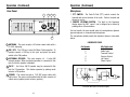
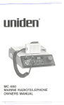
RCI-5054DX
AM/FM/SSB/CW 6 Meter
Amateur Mobile Transceiver
RF PWR
RCI−5054 DX
VOL
MIC
SQ
OFF
CLR
NB/ANL
R.BEEP
SPLIT
PRG
MAN
SHF
DIM
SWR
SCAN
MEM
ENT
LOCK
RF GAIN
LSB
CW
USB
AM
FM
Owner's Manual
2
3
3
4
4
4
6
6
10
11
12
13
13
14
PA
Receive Scanning ...............................................................
Split Function ......................................................................
Memory Function ..................................................…...........
Memory Channel Scanning ...................................................
Metering .............................................................................
Chapter 6 Frequency Scanning .........................................
All-Frequency Scanning .......................................................
Memory Scanning ...............................................................
Chapter 7 Offset (Split) Frequency Operation ....…............
14
14
14
15
15
16
16
17
18
WARRANTY ..............………….......................... Inside Back Cover
-1-
Chapter 1 Specifications
Chapter 2 Introduction
GENERAL
Congratulations on your purchase of an RCI-5054DX 6 meter
amateur radio. Your RCI-5054DX is designed to provide troublefree service and state-of-the-art communications in the 6 meter
band. Please read this manual thoroughly to ensure proper
performance.
Model
RCI-5054DX
Frequency Range :
50.000 ~ 54.000 MHz
Tuning Steps
100 Hz, 1 KHz, 10 KHz, 100 KHz, 1 MHz
Emission
USB, LSB, CW, AM, FM
Frequency Control
Phase-Lock-Loop Synthesizer
Frequency Tolerance
0.005%
IMPORTANT
Frequency Stability
0.001%
Operating
Temperature
-10OC to +50OC
Range
Antenna Impedance
50 ohm
Meter Function
Plug-In (6-Pin), 400 Ω Dynamic PTT
RF Output, RX Receive Signal Strength, SWR
Input Voltage
13.8 V DC
Dimensions
7 3/4" (W) x 10 3/4" (L) x 2 3/8" (H)
Weight
4 lb. 3 oz.
Microphone
TRANSMITTER
RF Power Output
RF Transmit Modes
25W PEP (USB/LSB)
10W RMS (CW/AM/FM)
USB, LSB, CW, AM, FM
Modulation
UHF Type, 50 Ω
16F3, A3E, J3E, A1A
Spurious Emissions
-50 dB
Carrier Suppression
-50 dB
Antenna Connector
Image Rejection Ratio
AGC Figure of Merit
Audio Power Output
Unpacking
The following items are included with our RCI-5054DX. Carefully
remove and examine all materials from the packing carton. If any
items are missing or appear damaged, please contact your dealer
immediately. Each unit should include:
(1) RCI-5054DX Transceiver
(2) Dynamic Microphone with remote frequency adjustment
switches
(3) Power Cord
(4) Mounting Bracket & Hardware
RECEIVER
Sensitivity
To operate this radio, you must possess and amateur radio
operator's license issued by the FCC. Operation of this unit without
proper licensing is ILLEGAL and can result in severe penalties.
AM/CW : 0.5 uV for 10dB Sinad
FM : 0.25uV for 12dB Sinad
USB/LSB : 0.15uV for 10dB Sinad
-65 dB
SSB/CW/AM : 80dB at 50mV for a 10dB change in
Audio Output
2.5W
(5) Installation Hardware
(6) Owner's Manual
(7) Warranty Registration Card
It is recommended that you save the packing materials for future
storage or shipping.
( SPECIFICATIONS SUBJECT TO CHANGE WITHOUT NOTICE )
-2-
-3-
Chapter 3 Installation
The RCI-5054DX is easy to install. All necessary parts (less the
antenna and coax cable) have been included to facilitate
installation.
CAUTION
Voltage above 15 VDC will damage the unit. Be sure to check the
source voltage before connecting the power cord.
Transceiver Mounting
Choose a suitable location for the transceiver that will allow easy
access to the front panel as well as proper air circulation to the
back of the unit. If you are installing the unit in a vehicle, attach the
mounting bracket first, then attach the transceiver to the mounting
bracket using the hardware provided. Before making any electrical
connection, ensure that the transceiver is turned off and the
vehicle's battery is disconnected.
Power Connection
The transceiver operates off of any 12 to 13.8 VDC source.
Beware of voltage drops caused by operating from Cigarette Lighter
Plugs or long DC wire runs. Sometimes it is best to connect direct
to the battery for best RF output and Tx audio quality
NOTE
The condition of a vehicle's electrical system can affect the operation of
your RCI-5054DX.. A low battery, worn generator/alternator, or poor
voltage regulator will impair performance of the unit as well as the
vehicle.
If an AC power supply is used with your radio, it must be regulated
and rated for at least 7 Amps continuous. Low voltage while under
load will cause reduced receiver gain and low transmitter output
with possible distortion and splatter.
-4-
-5-
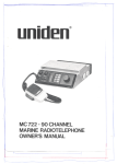
Chapter 4 Operation
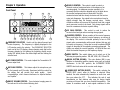
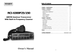
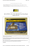
Front Panel
1
23
22
3
5
2
RF PWR
RCI−5054 DX
4
MIC
VOL
SQ
OFF
CLR
NB/ANL
R.BEEP
SPLIT
PRG
MAN
SHF
DIM
SWR
SCAN
MEM
ENT
LOCK
RF GAIN
LSB
CW
PA
USB
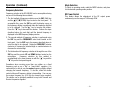
6. RF GAIN CONTROL: This control is used to reduce the
receiver's front-end gain when receiving strong signals.
AM
9
24
10
15
11
16
13
12
17
18
14
19
FM
21
20
7
21
6
8
1. FREQUENCY SELECTOR: Used to set the desired transmit and
receive frequency. The frequency is digitally displayed in the
LCD window next to the selector. The FREQUENCY SELECTOR
knob next to the LCD display, allows changing each digit on the
frequency display by first placing the frequency display cursor
(using SHF button) below the desired digit and then turning the
selector knob.
2. RF POWER CONTROL: This control adjust the Transmitter’s RF
power output level.
3. MIC GAIN CONTROL: This feature adjust the microphone gain
for the transmit and PA modes. Experiment with this control for
the setting that will provide best audio quality.
Avoid
overmodulation, which causes interference to adjacent stations
and “splatter”.
4. ON/OFF VOLUME CONTROL: Turn clockwise to apply power to
the radio and to set the desired listening level.
-6-
5. SQUELCH CONTROL: This control is used to control or
eliminate receiver background noise in the absence of an
incoming signal. For maximum receiver sensitivity, it is
necessary that the control be adjusted only to the point where
the receiver background noise is eliminated. Turn fully
counterclockwise and then slowly clockwise until the receiver
noise just disappears. Any signal to be received must now be
slightly stronger than the average received noise. Further
clockwise rotation will increase the threshold level that a signal
must overcome in order to be heard. Only strong signals will be
heard at a maximum clockwise squelch setting.
7. CLARIFIER CONTROL: Allows variation of the receive frequency
above and below the selected receive frequency as shown on
the display. This control is intended primarily to tune in SSB
signals when communicating with several stations that may not
be exactly on frequency. It may also be used to optimize AM/FM
signals as described in the operating procedure paragraph. The
clarifier can adjust the receive frequency ±2.5KHz but does not
affect the transmit frequency or the frequency display.
8. MODE SWITCH: This switch allows you to select one of the
following six operating modes: FM, AM, USB, LSB, CW and PA.
9. NB/ANL BUTTON (NB/ANL): The noise blanker (NB) is very
effective in eliminating repetitive impulse noise such as ignition
interference. In the ANL position, the AUTOMATIC NOISE
LIMITER also limits noise at the receiver audio stages.
10. ROGER BEEP BUTTON (R.BEEP): This switch activates the
ROGER BEEP circuit, when its function is selected. When
enabled, the radio automatically transmits an audio tone each
time you release the PTT. This indicates the end of each
transmission so that stations who may be having trouble
receiving will know that you have finished transmitting. This
feature is sometimes used in weak signal conditions or other
-7-
special circumstances. We discourage use of this feature in
normal operation, as it can be annoying to other operators.
11. SPLIT BUTTON (SPLIT): Enables the offsetting of the
transmitter frequency by up to +/- 2 Mhz (programmable) for
FM repeater operation.
UP/DOWN buttons on the microphone. Pressing this switch
again will re-enable the frequency selectors.
21. UP/DOWN SELECTOR: These buttons are used to increase or
decrease the frequency digit above the SHF cursor on the
display.
12. PROGRAM BUTTON (PRG): Used to pre-program operating or
scanning frequencies into memory. See the OPERATION section
of this manual for details.
13. MANUAL BUTTON (MAN): Used to return the unit to manual
mode.
14. SHIFT BUTTON (SHF): Determines which digit will change
when changing frequencies, by placing a “cursor” under the
desired digit. Allows frequency to be changed in 100 Hz, 1KHz,
10KHz, 100KHz and 1 MHz increments.
15. DIM BUTTON (DIM): This button adjusts the display
backlighting in four different steps to best match the ambient
light.
16. SWR BUTTON (SWR): Used to check relative SWR.
17. SCAN BUTTON (SCAN): Used to enable the scanning of
frequencies. See the PROGRAMMING and SCANNING section of
this manual for detailed information on using the scan control.
18. MEMORY BUTTON (MEM): Used to program often used
frequencies in memory. Detailed information on how to use this
control is provided in the PROGRAMMING section of the manual.
19. ENTER BUTTON (ENT): Used to program frequencies in
memory. See PROGRAMMING section.
20. LOCK BUTTON (LOCK): Disables the Frequency Selector
Control, UP/DOWN buttons on the front control panel and remote
-8-
-9-
Operation (Continued)
Operation (Continued)
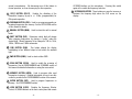
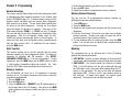
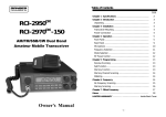
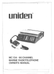
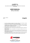
Rear Panel
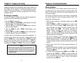
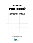
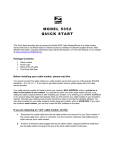
Microphone
1
2
3
4
1. PTT SWITCH: The Push-To-Talk (PTT) switch controls the
transmit and receive function of the radio. Push to transmit and
release to receive.
2. REMOTE UP/DOWN SWITCH: The digit on the frequency
display above the SHF “cursor” can be stepped up or down by
pushing either of these buttons.
For best results, the user should select a low-impedance dynamic
type microphone or a transistorized microphone.
5
The microphone should provide the functions shown in schematic
below.
6 WIRE MIC CABLE
1. ANTENNA: This jack accepts a 50 ohms coaxial cable with a
PL-259 style plug.
2. CW KEY: The CW key is used for Morse Code operation. To
operate connect a CW key to this jack, and place the mode
switch in the CW position.
3. EXTERNAL SPEAKER: This jack accepts a 4 - 8 ohm 5W
external speaker. When an external speaker is connected to this
jack, the built-in speaker is disabled.
Pin Number
1
2
3
4
5
6
Mic Cable Lead
Audio Shield
Audio Lead
Transmit Control
Receive Control
Up Control
Down Control
4. PA SP.: An 8 ohm, 4W PA speaker may be connected to this
jack for PA operation. This feature operates by placing mode
selector in PA position.
5. POWER: This socket accepts a 13.8 VDC power cable with
built-in fuse. The power cord provided with the radio consists of
a black wire (negative) and a red wire (positive ).
Transceiver Microphone Schematic Diagram
- 10 -
- 11 -
Mode Selection
Operation (Continued)
To Select an operating mode, rotate the MODE selector, and place
it in the desired operating mode position.
Frequency Selection
Frequency selection in the RCI-5054DX can be accomplished using
any one of the following three methods:
1. The first method of frequency selection uses the SHF (Shift) key
and the ▲(UP)/▼(DOWN) keys located on the front panel. To
accomplish this, press the SHF key until the display cursor on
the frequency display is positioned under the frequency digit that
is to be changed. Use the”▲” key to increase the number.
Press the “▼” key to decrease the number. Perform the steps
described above for each digit until the desired frequency is
displayed in the LCD frequency display window.
RF Power Control
This feature allows the adjustment of the RF output power
continuously over the range of 1W through 25W.
2. The second method of frequency selection is performed using
the SHF key and the FREQUENCY select knob located on the
front panel. Use the SHF key in the manner described above to
select the digit to be changed. Rotate the FREQUENCY selector
clockwise to increase the selected digit or counterclockwise to
decrease the selected digit.
3. The third method of frequency selection is through the use of the
SHF key and the remote UP and DOWN buttons located on the
microphone.
Frequency selection by this method is
accomplished in the same manner as with the “▲” key and the
“▼” key on the front panel keypad.
Sometimes when receiving more than one station on a fixed
frequency such as on a “Net” or “round table” operation, it is
convenient to be able to vary the receive frequency slightly without
changing the transmit frequency. To do this, rotate the clarifier
control while an off frequency station is transmitting. You can vary
the receiver frequency by ±2.5 KHz for clearest voice reception.
The clarifier can be optionally modified to vary both Transmit and
Receive frequencies together.
- 12 -
- 13 -
Chapter 5 Programming
4. Set the desired frequency you wish to store in memory.
5. Press the ENT button.
6. Repeat the procedure to program other memory channels.
Receive Scanning
The receive scanning feature helps locate active frequencies within
a preprogrammed band segment anywhere on the 6 Meter band
(refer to SCANNING, page 16). To begin scanning, slowly turn the
Squelch control clockwise until the receiver noise disappears.
Next, press the scan button. The unit should start scanning from
the lower to the higher frequencies. Pressing the Scan button
again will change the direction of scanning. Each press of the
Scan button displays "SCAN+" or "SCAN-" on the LCD display.
The scan will stop on any active frequency for the duration of the
transmission. After the on-frequency activity stops, the RCI5054DX will resume scanning after about a 2 second pause. To
pause the Scan mode, turn the Squelch control counterclockwise
until you hear receiver noise. To deactivate the scan function,
press the MAN button.
Memory Channel Scanning
Split Function
Metering
This function enables you to split the transmit and the receive
operating frequency by a pre-programmed offsett. This feature is
necessary for operation with FM repeaters. (See OFFSET
FREQUENCY OPERATION, pg. 18 for more information). To split
frequencies, press the MAN button and the SPLIT button to select
+ split frequency (transmitter higher than receiver). For - split,
press the SPLIT button again (transmitter lower than receiver).
The segmented bars on the left-hand side of the LCD display
provides the following information:
Memory Function
The RCI-5054DX can store up to 10 frequencies in memory
locations 0 to 9. To program a frequency into memory, follow the
procedure described below:
1. Press the MAN button.
2. Press the PRG button.
3. Press the MEM button. ("MEMORY" and "0" should appear on
the left-hand side of the LCD display). Each press of the MEM
button advances the memory location one step at a time from
"0" to "9".
- 14 -
You can scan the 10 pre-programmed memory locations by
following the procedure described below:
1. Press MAN button.
2. Press the MEM button.
3. Slowly turn the Squelch knob clockwise until the receiver noise
disappears.
4. Press the Scan button. The unit will scan from lower to higher
memory locations. Pressing scan again will cause the unit to
scan from higher to lower memory locations.
5. To stop scanning while on a memory location, press the MAN
button. You can also turn the Squelch knob counterclockwise
until you hear the receiver noise.
1. S/RF METER: Provides a relative indication of the transmit RF
output power while transmitting or signal strength while receiving
2. SWR METER: This function allows the checking of relative
SWR. To use this function, set the unit to AM mode and push
the SWR button on the front panel while holding down the PTT
switch on the microphone. The bars on the meter will indicate
approximate SWR. If there is no bar, your antenna system is
well matched. If several bars appear, the antenna needs
adjustment. The fewer the bars, the better the match.
- 15 -
.Chapter
6 Frequency Scanning
Frequency Scanning (Continued)
Frequency scanning can be achieved by either of two methods: the
first method involves scanning of all frequencies between a pre-set
upper and lower scan frequency. The second method permits the
scanning of frequencies previously programmed in the memory
locations 0 thru 9.
Memory Scanning
All-Frequency Scanning
The first step in utilizing the memory scan function is programming
the desired frequencies into the memory locations 0 thru 9 by
performing the following steps:
To allow All-Frequency scanning, the user must first program the
upper and lower scan limit frequencies as follows:
1. Press the PRG (Program) key.
2. Press the SCAN key. ("PRG SCAN+" should appear in the lower
right-hand corner of the display window.)
3. Using the SHF key and the UP and DOWN arrows, select the
upper scan limit frequency.
4. Press the SCAN key again. ("SCAN-" should appear in the
display window.)
5. Using the SHF key and UP and DOWN arrows, select the lower
scan limit frequency, then press the ENT key.
The upper and lower scan limits have now been programmed. To
activate the scan feature, return the radio to manual operation and
press the SCAN button. If the display shows "SCAN+", the radio
will scan from the lower limit to the upper limit. If "SCAN-" is
displayed, the unit will scan from the upper limit to the lower limit.
To change from "SCAN+" to "SCAN-" or vice versa, press SCAN.
NOTE
Whichever upper and lower scan limits are programmed in, are
also the upper and lower operating limits of the radio. The radio
will not operate above or below the scan limits last programmed
in. Full band coverage can be returned by reprogramming the
original band edges.
- 16 -
The RCI-5054DX has 10 non-volatile memory locations which can
be programmed to any frequency within the operating range of the
radio. The scan function of the unit can scan the frequencies in the
10 memory locations.
1. With the radio operating in the manual mode, press the PRG
(Program) key.
2. Press the MEM key. "PRG" should display in the lower righthand corner of the LCD display. "MEM" should display in the
upper left portion of the display. A number between 0 and 9 will
display directly below MEM. This number represents the
memory location currently being shown on the frequency
display. Pressing the MEM key will increase the memory
counter to the next memory location and the frequency in that
memory location will be displayed.
3. Set the new frequency to be stored in the memory location
displayed by using the SHF key and the UP and DOWN arrows.
After the desired frequency is indicated, press ENT. This will
overwrite whatever frequency had been previously stored at this
location.
4. Repeat steps 2 and 3 for all of the memory locations to be
programmed.
5. After the desired memory locations have been programmed with
frequencies, return the unit to the manual mode of operation by
pressing the MAN key.
6. To initiate memory scanning, press MEM and then SCAN. The
display will show "SCAN+" or "SCAN-" to indicate whether the
radio is scanning from the lowest to the highest memory location
or vice versa. To return the radio to normal (non-scanning)
operation, press the MAN key.
- 17 -
Chapter 7 Offset (Split) Frequency Operation
Memo
The split frequency function offsets the transmitter frequency either
above or below the receiver frequency by a user-programmable
amount. This is necessary for operating on FM repeaters. In the
following example, the programming of a 1 MHz offset will be
described. Before attempting to program the offset frequency,
ensure that the radio is operating in the manual mode by pressing
the MAN key.
NOTE: FM repeaters may require that a sub-audible CTCSS tone be
transmitted to gain access to the repeater. The RCI-5054DX can be
equipped with an optional CTCSS encoder.
TO PROGRAM TX OFFSET:
1. Press the PRG (Program) key.
2. Press the SPLIT key. The LCD display will indicate 00000 with
PRG and SPLIT showing in the lower left-hand corner of the
display.
3. Using the SHF key and the UP and DOWN arrows as described
earlier, program the display to read 10000.
4. Press ENT. A 1 MHz offset has now been programmed into the
radio.
5. Return the radio to manual operation by pressing the MAN key.
6. Using the SHF key and the UP and DOWN arrows as described
previously, set the radio to the desired receive frequency.
7. Press SPLIT. Either "SPLIT+" or "SPLIT-" will be displayed in
the lower right corner of the display. If "SPLIT+" is displayed,
the transmitter will be offset 1 MHz above the receive frequency
when keyed. If "SPLIT-" is displayed, the transmitter will be
offset 1 MHz below the receive frequency.
NOTE
When the transmitter is keyed, the frequency display will change to
show the frequency being transmitted.
- 18 -
- 19 -
LIMITED WARRANTY
Ranger Communications, Inc. (Ranger) warrants to the original purchaser ONLY this
product against defects in material or workmanship as follows:
1) Ranger warrants the product to be free of defects in material or workmanship (parts
and labor on this product) for a period of two (2) year from the original date of
purchase as shown on the original bill of sale, receipted invoice, or other proof of
purchase. After this period, the original purchaser normally pays for any labor at the
prevailing rates at the factory. This warranty is limited to the transceiver only.
2) In the event of a defect during the warranty period, Ranger shall, at its option, repair or
replace the defective product. Such action shall constitute the purchaser’s
exclusive remedy under this warranty.
3) A RETURN AUTHORIZATION NUMBER must be obtained from the Ranger Customer
Service Department before any return for warranty repair will be accepted. Send the
defective product Freight-Prepaid, along with proof of the date of purchase
(photocopy of the original invoice or receipt) to:
Ranger Communications, Inc.
401 W. 35th Street, Suite B
National City, CA 91950
PHONE: (800) 446-5778
FAX: (619) 426-3788
401 W. 35th Street, Suite B
National City, CA91950
(800) 446-5778
FAX (619) 426-3788
Email: [email protected]
http: //www.rangerusa.com
Email: [email protected]
4) This warranty does not cover cosmetic damage or damage due to acts of God,
accident, misuse, abuse, negligence, improper installation, UNAUTHORIZED
MODIFICATION or any action in violation of the product’s instruction manual. This
warranty is valid ONLY in the United States of America.
5) This warranty is valid ONLY if the serial number appears on the product. If the
warranty sticker has been removed or cut, the warranty is normally voided.
6) Ranger reserves the right to void a warranty or make reasonable charges for the repair
of a product which displays evidence of misuse, abuse, neglect, accident or
modification of the basic design.
7) Warranties give you, the buyer, specific legal rights. You may also have other rights
which may vary from state to state. This warranty is extended only to Ranger
products purchased and shipped to locations in the United States of America or its
possessions.
8). Radios that have parts removed, cut or clipped, or the PCB is found to have been
damaged will not be repaired under warranty. Radios that have been modified will be
returned to the original factory condition when returned to us.
9). "Limited" means that we will repair problems that are caused by factory defects, only
for the above mentioned products and time limit, at no charge. Work performed by
qualified technicians which did not cause any damage to the radio normally will
normally not void the warranty. Problems or damage caused by unqualified or
misinformed technicians, operator abuse can be repaired for a charge.
PRINTED IN TAIWAN
AT5054010A
AT2950011H
- 20 -
- 21 -