1
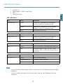
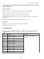
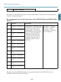
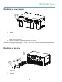
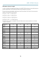
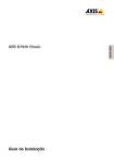
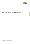
INSTALLATION GUIDE
ENGLISH
AXIS Q7920 Chassis
Legal Considerations
Regulatory Information
Video and audio surveillance can be regulated by laws that
vary from country to country. Check the laws in your local
region before using this product for surveillance purposes.
Europe
Liability
Every care has been taken in the preparation of this
document. Please inform your local Axis office of any
inaccuracies or omissions. Axis Communications AB cannot
be held responsible for any technical or typographical errors
and reserves the right to make changes to the product and
manuals without prior notice. Axis Communications AB
makes no warranty of any kind with regard to the material
contained within this document, including, but not limited
to, the implied warranties of merchantability and fitness for
a particular purpose. Axis Communications AB shall not
be liable nor responsible for incidental or consequential
damages in connection with the furnishing, performance
or use of this material. This product is only to be used for
its intended purpose.
Intellectual Property Rights
Axis AB has intellectual property rights relating to
technology embodied in the product described in this
document. In particular, and without limitation, these
intellectual property rights may include one or more of the
patents listed at http://www.axis.com/patent.htm and one
or more additional patents or pending patent applications
in the US and other countries.
Equipment Modifications
This equipment must be installed and used in
strict accordance with the instructions given in the
user documentation. This equipment contains no
user-serviceable components. Unauthorized equipment
changes or modifications will invalidate all applicable
regulatory certifications and approvals.
Trademark Acknowledgments
AXIS COMMUNICATIONS, AXIS, ETRAX, ARTPEC and VAPIX
are registered trademarks or trademark applications of Axis
AB in various jurisdictions. All other company names and
products are trademarks or registered trademarks of their
respective companies.
Apple, Boa, Apache, Bonjour, Ethernet, Internet Explorer,
Linux, Microsoft, Mozilla, Real, SMPTE, QuickTime, UNIX,
Windows, Windows Vista and WWW are registered
trademarks of the respective holders. Java and all
Java-based trademarks and logos are trademarks or
registered trademarks of Oracle and/or its affiliates.
UPnPTM is a certification mark of the UPnPTM Implementers
Corporation.
Support
Should you require any technical assistance, please contact
your Axis reseller. If your questions cannot be answered
immediately, your reseller will forward your queries through
the appropriate channels to ensure a rapid response. If you
are connected to the Internet, you can:
• download user documentation and software updates
• find answers to resolved problems in the FAQ database.
Search by product, category, or phrase
• report problems to Axis support staff by logging in to
your private support area
• chat with Axis support staff (selected countries only)
• visit Axis Support at www.axis.com/techsup/
Learn More!
Visit Axis learning center www.axis.com/academy/ for
useful trainings, webinars, tutorials and guides.
This product complies with the applicable CE marking
directives and harmonized standards:
• Electromagnetic Compatibility (EMC) Directive
2004/108/EC. See Electromagnetic Compatibility
(EMC), on page 2 .
• Low Voltage (LVD) Directive 2006/95/EC. See Safety,
on page 3 .
• Restrictions of Hazardous Substances (RoHS) Directive
2011/65/EU. See Disposal and Recycling, on page 3 .
A copy of the original declaration of conformity may be
obtained from Axis Communications AB. See Contact
Information, on page 3 .
Electromagnetic Compatibility (EMC)
This equipment has been designed and tested to fulfill
applicable standards for:
• Radio frequency emission when installed according to
the instructions and used in its intended environment.
• Immunity to electrical and electromagnetic phenomena
when installed according to the instructions and used
in its intended environment.
USA
Using an unshielded network cable (UTP) – This equipment
has been tested using an unshielded network cable (UTP)
and found to comply with the limits for a Class A digital
device, pursuant to part 15 of the FCC Rules. These limits
are designed to provide reasonable protection against
harmful interference when the equipment is operated in a
commercial environment. This equipment generates, uses,
and can radiate radio frequency energy and, if not installed
and used in accordance with the instruction manual, may
cause harmful interference to radio communications.
Operation of this equipment in a residential area is likely to
cause harmful interference in which case the user will be
required to correct the interference at his own expense.
Using a shielded network cable (STP) – This equipment
has also been tested using a shielded network cable (STP)
and found to comply with the limits for a Class B digital
device, pursuant to part 15 of the FCC Rules. These limits
are designed to provide reasonable protection against
harmful interference in a residential installation. This
equipment generates, uses and can radiate radio frequency
energy and, if not installed and used in accordance with
the instructions, may cause harmful interference to radio
communications. However, there is no guarantee that
interference will not occur in a particular installation. If
this equipment does cause harmful interference to radio or
television reception, which can be determined by turning
the equipment off and on, the user is encouraged to try to
correct the interference by one or more of the following
measures:
• Reorient or relocate the receiving antenna.
• Increase the separation between the equipment and
receiver.
• Connect the equipment into an outlet on a circuit
different from that to which the receiver is connected.
• Consult the dealer or an experienced radio/TV
technician for help.
Canada
This Class B digital apparatus complies with Canadian
ICES-003.
Europe
This digital equipment fulfills the requirements for RF
emission according to the Class B limit of EN 55022.
This product fulfills the requirements for emissions and
immunity according to EN 50121-4 and IEC 62236-4
railway applications.
This product fulfills the requirements for immunity
according to EN 61000-6-1 residential, commercial and
light-industrial environments.
This product fulfills the requirements for immunity
according to EN 61000-6-2 industrial environments.
This product fulfills the requirements for immunity
according to EN 55024 office and commercial environments
Australia/New Zealand
This digital equipment fulfills the requirements for RF
emission according to the Class B limit of AS/NZS CISPR 22.
Japan
この装置は、クラスB 情報技術装置です。この装
置は、家庭環境で使用することを目 的としていま
すが、この装置がラジオやテレビジョン受信機に
近接して使用されると、 受信障害を引き起こすこ
とがあります。 取扱説明書に従って正しい取り扱
いをして下さい。
Korea
이 기기는 가정용(B급) 전자파적합기기로서 주로
가정에서 사용하는 것을 목적으로 하며, 모든 지
역에서 사용할 수 있습니다.
FreeRTOS
The software in this product is based on
FreeRTOS version 7.2.0. See www.freertos.org for
more information.
Source code for this version of FreeRTOS can be provided
from Axis Communications AB upon request.
Safety
This product complies with IEC/EN/UL 60950-1, Safety of
Information Technology Equipment.
Disposal and Recycling
When this product has reached the end of its useful life,
dispose of it according to local raws and regulations. For
information about your nearest designated collection point,
contact your local authority responsible for waste disposal.
In accordance with local legislation, penalties may be
applicable for incorrect disposal of this waste.
Europe
This symbol means that the product shall not be
disposed of together with household or commercial waste.
Directive 2012/19/EU on waste electrical and electronic
equipment (WEEE) is applicable in the European Union
member states. To prevent potential harm to human health
and the environment, the product must be disposed of in
an approved and environmentally safe recycling process.
For information about your nearest designated collection
point, contact your local authority responsible for waste
disposal. Businesses should contact the product supplier for
information about how to dispose of this product correctly.
This product complies with the requirements of
Directive 2011/65/EU on the restriction of the use of
certain hazardous substances in electrical and electronic
equipment (RoHS).
China
This product complies with the requirements of the
legislative act Administration on the Control of Pollution
Caused by Electronic Information Products (ACPEIP).
Contact Information
Axis Communications AB
Emdalavägen 14
223 69 Lund
Sweden
Tel: +46 46 272 18 00
Fax: +46 46 13 61 30
www.axis.com
AXIS Q7920 Chassis
Safety Information
Hazard Levels
DANGER
Indicates a hazardous situation which, if not avoided, will result in
death or serious injury.
WARNING
Indicates a hazardous situation which, if not avoided, could result
in death or serious injury.
CAUTION
Indicates a hazardous situation which, if not avoided, could result
in minor or moderate injury.
NOTICE
Indicates a situation which, if not avoided, could result in damage
to property.
Other Message Levels
Important
Indicates significant information which is essential for the product
to function correctly.
Note
Indicates useful information which helps in getting the most out
of the product.
5
ENGLISH
Read through this Installation Guide carefully before installing the product. Keep the Installation
Guide for future reference.
AXIS Q7920 Chassis
Safety Instructions
NOTICE
• The Axis product shall be used in compliance with local laws and regulations.
• To use the Axis product outdoors, or in similar environments, it shall be installed in an
approved outdoor housing.
• Store the Axis product in a dry and ventilated environment.
• Avoid exposing the Axis product to vibration, shocks or heavy pressure.
• Do not install the product on unstable or vibrating brackets, surfaces or walls.
• Use only applicable tools when installing the Axis product. Excessive force could cause
damage to the product.
• Do not use chemicals, caustic agents, or aerosol cleaners. Use a damp cloth for cleaning.
• Use only accessories that comply with technical specification of the product. These can be
provided by Axis or a third party.
• Use only spare parts provided by or recommended by Axis.
• Do not attempt to repair the product by yourself. Contact Axis support or your Axis
reseller for service matters
Transportation
NOTICE
• When transporting the Axis product, use the original packaging or equivalent to prevent
damage to the product.
6
AXIS Q7920 Chassis
Installation Guide
This installation Guide provides instructions for installing AXIS Q7920 Chassis on your network.
1. Make sure the package contents, tools and other materials necessary for the installation
are in order. See page 7 .
2. Study the hardware overview. See page 8 .
3. Install the hardware. See page 10.
Package Contents
•
•
•
•
•
•
Video encoder chassis
AXIS Q7920
Cover plates
1 1–port front panel cover
6 2–port front panel covers
2 AC power cords
Europe
UK
US, Canada and Japan
Australia
Switzerland
Denmark
South Korea
Argentina
Terminal connectors
28 14–pin terminal connectors
14 2–pin terminal connectors
Printed materials
AXIS Q7920 Chassis Installation Guide (this document)
Included accessories
4 feets
7
ENGLISH
Installation Steps
AXIS Q7920 Chassis
Hardware Overview
1
2
5
1
2
3
4
5
6
7
6
4
3
7
Network connector 1–4 RJ45
Network port 1–4 SFP
Fan tray cover
Grounding screw
I/O terminal connector
RS-485 connector
Power in/out connector
Note
SFP modules are not included in the delivery of AXIS Q7920.
1
2
6
1
2
3
3 4
5
7
Network LED 1–4 SFP
Network LED 1–4 RJ45
PSU LED 1–2
8
AXIS Q7920 Chassis
4
5
6
7
ENGLISH
Fan LED 1–2
Power supply 1–2 (PSU 1 and PSU 2)
Slot 1
Front panel cover
LED indicators
LED
Color
Indication
Network RJ45 1–4
Green
Steady for a connection to 1000 Mbit/s
network. Flashes for network activity.
Amber
steady for a connection to 10/100 Mbit/s
network. Flashes for network activity.
Unlit
No network connection.
LED
Color
Indication
Network SFP 1–4
Green
Steady for a connection to 1000 Mbit/s
network. Flashes for network activity.
Unlit
No network connection.
LED
Color
Indication
PSU 1–2
Green
PSU1 and PSU2 are connected and turned on.
Red
Indicates a fault in PSU1 or PSU2. It also
indicates if PSU1 or PSU2 are disconnected or
turned off.
LED
Color
Indication
Fan LED 1–2
Green
Both fans are working.
Flashes green/red
Indicates a fault in one fan.
Red
Indicates faults in both fans.
Note
In case of a faulty power supply, replace it with a new one. See Replacing a power supply,
on page 14
In case of a faulty fan replace the fan tray with a new one. See Replacing a fan tray,
on page 14
9
AXIS Q7920 Chassis
Specifications
Operating Conditions
The AXIS Q7920 is intended for indoor use only.
Product
Temperature
Humidity
AXIS Q7920
0 °C to 45 °C
(32 °F to 113 °F
10-85% RH (non-condensing)
Power Consumption
Product
AC
AXIS Q7920
100–240 V AC, max 365 W
Install the Hardware
General Placement Requirements
•
•
•
•
Power source within 1.8 meters.
There must be a minimum of 5 cm free space on the bottom, front, rear and on both
sides of the AXIS Q7920 to ensure adequate ventilation.
Do not stack other units or objects directly on top of the AXIS Q7920. The mounting
brackets are not designed to support more than 1 unit.
No excessive dust.
Connect Power
The AXIS Q7920 has two On/Off switches. To switch off power to the AXIS Q7920 both power
supplies must be switched off.
Before switching on power to the AXIS Q7920, make sure the unit is properly grounded by using
the grounding screw.
Ensure that the correct AC power cord for your region is used.
10
AXIS Q7920 Chassis
WARNING
• To prevent the risk of electrical shock when in contact with the unit casing, only
earthed/grounded power cords should be used to power the AXIS Q7920.
• If a foreign object is accidently dropped into the video encoder chassis, always disconnect
power before attempting to remove the object.
Axis video encoder blades
S/N — (Serial Number) is identical to the units MAC/Ethernet address.
P/N — is the products model number.
Bus Connector — This is the physical interface to the I/O terminal connector on the chassis.
Mounting Axis video encoder blades
The AXIS Q7920 can accommodate 14 Axis video encoder blades. The slots for these are numbered
1–14 from left to right. There are 4 slot groups in AXIS Q7920. Slot 1–4, slot 5–7, slot 8–11
and slot 11–14
The first blade should be inserted in slot 1. After that all slots can be used without any further
regulations. See Optimizing Performance, on page 15 for information of how to optimize the
performance of the AXIS Q7920.
In order to get full functionality from AXIS Q7920 the blade in slot 1 should be an AXIS Q7436,
AXIS Q7404, AXIS Q7414, AXIS P7224 or newer.
Follow these steps to mount an Axis video encoder blade in the AXIS Q7920:
1. Remove the front panel cover from the slot in to which the video encoder blade will be
mounted.
2. Slide the video encoder into place , using the guides as an aid.
3. Fix the video encoder in place, using the screws from the front panel cover.
The AXIS Q7920 supports hot-swap of video encoder blades. A blade can be removed and/or
inserted without the need of switch off the AXIS Q7920.
NOTICE
Front panel covers should be used on all empty slots.
11
ENGLISH
• Protection against overcurrents, short circuits and earth faults should be provided in
the building installation.
AXIS Q7920 Chassis
Unit connectors
Rear Connectors
Network connector : Standard RJ45 connector, designed for 10/100/1000 Mbps.
Network connector : Standard SFP connector, designed for 1000 Mbps.
RS-485 connector: Usually used for connecting Pan Tilt Zoom devices.
Power In/Out Connectors: 12 V DC 100 mA out. This connector could be used to supply power to
external units.
I/O Terminal Connectors: Provides the physical interface for up to 12 I/Os.
Chassis ID
Chassis ID 0–15: Sets a chassis ID. Used in multichassis installations.
Chassis ID A-P: Currently not used.
Pin assignments
Pin Assignments for RS485 Connector - AXIS Q7900 and AXIS Q7920
Chassis
Pin
Function
Description
1
Channel 1, RS485A
2
Channel 1, RS485B
A half-duplex RS485 interface for
controlling auxiliary equipment such as
PTZ devices.
3
Channel 2, RS485A
4
Channel 2, RS485B
5
Channel 3, RS485A
6
Channel 3, RS485B
7
Channel 4, RS485A
8
Channel 4, RS485B
9
Channel 5, RS485A
10
Channel 5, RS485B
11
Channel 6, RS485A
12
AXIS Q7920 Chassis
12
Channel 6, RS485B
Pin assignments for the I/O Connector of the AXIS Q7900 and AXIS Q7920
Chassis
Pin
Function
Description
1
Channel 1, Configurable
I/O 1
2
Channel 2, Configurable
I/O 1
3
Channel 3, Configurable
I/O 1
4
Channel 4, Configurable
I/O 1
5
Channel 5, Configurable
I/O 1
Digital input - Connect to GND
to activate, or leave floating (or
unconnected) to deactivate.
Digital output - Uses an open
drain NFET transistor with the
source connected to GND. If
used with an external relay,
a diode must be connected
in parallel with the load, for
protection against voltage
transients.
6
Channel 6, Configurable
I/O 1
7
Channel 1, Configurable
I/O 2
8
Channel 2, Configurable
I/O 2
9
Channel 3, Configurable
I/O 2
10
Channel 4, Configurable
I/O 2
11
Channel 5, Configurable
I/O 2
12
Channel 6, Configurable
I/O 2
Min input = – 40 V DC
Max input = + 40 V DC
Max load = 100mA
Max voltage = + 40 V DC
(to the transistor)
This table is for the AXIS Q7436 blade. If using another blade in the AXIS Q7920, see the
Installation Guide for the specific product.
13
ENGLISH
This table is for the AXIS Q7436 blade. If using another blade in AXIS Q7920 see the Installation
Guide for the specific product.
AXIS Q7920 Chassis
Replacing a power supply
1
1
2
2
Screw
Handle
1. Turn off the power supply that needs to be replaced.
2. Loosen the screw located on the left side of the power supply and remove the power
supply using the handle.
3. Insert a new power supply and retighten the screw.
The AXIS Q7920 supports hot-swap of a PSU. A PSU can be removed and/or inserted without the
need of switch off the AXIS Q7920.
Replacing a fan tray
5
1
1
2
3
2
3
4
Screws x4
Lid fan
Fan tray
14
AXIS Q7920 Chassis
4
5
Fans
Fan power connectors x2
1. Remove the fan tray cover.
2. Disconnect the fans from the power connectors.
3. Gently pull out the fan tray.
4. Insert a new fan tray.
5. Connect the fans to the power connectors.
6. Mount the fan tray cover
The AXIS Q7920 supports hot-swap of a fan tray. A fan tray can be removed and/or inserted
without the need of switch off the AXIS Q7920.
Optimizing Performance
Firmware Upgrade
The AXIS Q7920 has an automated built-in function for firmware upgrade. If a blade that is inserted
in slot 1 in the AXIS Q7920 contains a newer firmware than the current one in AXIS Q7920. The
AXIS Q7920 will automatically be upgraded to the new firmware version. The upgrade may take up
to one minute to accomplish.
Network Redundancy
The network redundancy in AXIS Q7920 is controlled by software and requires that at least two
network connectors (either RJ45 or SFP) are connected. There are four uplink groups in AXIS Q7920,
each with a SFP and a RJ45 connector. The SFP connector has priority over the RJ45 connector.
In case of a malfunction in a connection the AXIS Q7920 will check for a connection in the
same uplink group or if needed check for a connection in another uplink group until a network
connection can be established.
Hot-swap
The AXIS Q7920 supports hot-swap of blades, fan tray and PSU. They can be removed and/or
inserted without affecting operation of the AXIS Q7920.
Rack Monitoring Daemon
In order to use the rack monitoring daemon function, the blade inserted in slot 1 must be an
AXIS Q7436, AXIS Q7404, AXIS Q7414, AXIS P7224 or newer.
15
ENGLISH
Follow these steps to replace a fan tray.
AXIS Q7920 Chassis
Maximum network output
In order to optimize the network performance of the AXIS Q7920 activate as many uplink groups as
possible (either RJ45 or SFP). Spread the blades evenly among the slot groups.
For every slot group activated an uplink group should be activated. See below for the connection
between slot groups and uplink groups.
Slot group 1: Slot 1–4. Uplink group 1
Slot group 2: Slot 5–7. Uplink group 2
Slot group 3: Slot 8–10. Uplink group 3
Slot group 4: Slot 11–14. Uplink group 4
The table below provides an example of how the blades can be evenly inserted in a 4, 6, 8 and
10 blades installation.
Number of
blades
4
6
8
10
Slot 1
X
X
X
X
X
X
X
Slot 2
X
Slot 3
Slot 4
X
Slot 5
Slot 6
X
X
X
X
Slot 7
X
Slot 8
Slot 9
X
X
X
X
X
Slot 10
X
Slot 11
Slot 12
X
X
X
X
Slot 13
X
X
Slot 14
X
X
16
AXIS Q7920 Chassis
Warranty Information
For information about Axis’ product warranty and thereto related information, see
www.axis.com/warranty/
ENGLISH
17
Installation Guide
AXIS Q7920 Chassis
© Axis Communications AB, 2013
Ver. M1.13
Date: June 2013
Part No. 51772