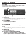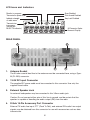
1
RMV25 / RMV50
RMU25 / RMU45
Owner's Manual
TABLE OF CONTENTS
INTRODUCTION ............................................................................................ 3
FCC Requirements ..................................................................................... 3
SAFETY WARNING INFORMATION ............................................................. 3
CONTROLS and INDICATORS ..................................................................... 5
FRONT PANEL ........................................................................................... 5
LCD Icons and Indicators .......................................................................... 6
REAR PANEL .............................................................................................. 6
BASIC OPERATION ...................................................................................... 7
RECEIVE .................................................................................................... 7
TRANSMITTING ......................................................................................... 7
ADVANCED OPERATION .............................................................................. 9
INSTALLATION ............................................................................................ 11
SERVICE ..................................................................................................... 11
2
INTRODUCTION
This Manual describes the operation for the RELM RM Series mobile radios.
The RM Series is full-featured FM transceivers designed for flexible mobile and base
station business communications in the VHF or UHF Land mobile frequency bands.
The RM Series mobile radios can be programmed with 128 channels. The RM Series
include a 16 segment, 8 character, alphanumeric display for channel display. The channel
frequency data is stored in an EEPROM and flash memory; thus, allowing the RM
mobiles to be easily programmed by dealers using personal computers with the PC
editing software.
FCC Requirements - RF Radiation Exposure-for Occupational Use Only
Your radio must be properly licensed by the Federal Communications Commission prior to
use. Your RELM Communications dealer can assist you in meeting these requirements.
Your dealer will program each radio with your authorized frequencies, signaling codes,
etc., and will be there to meet your communications needs as your system expands.
CAUTION
To ensure that your exposure to RF electromagnetic energy is within
the FCC allowable limits for occupational use, always adhere to the
following guidelines.
Antennas used for this transmitter must not exceed an antenna gain of 3dBi. The radio
must be used in vehicle-mount configurations with a maximum operating duty factor not
exceeding 50%, in typical push-to-talk configurations. This radio is NOT approved for use
by the general population in an uncontrolled environment. This radio is restricted
occupational use, work related operations only where radio operator must have the
knowledge to control the exposure conditions of its passengers and bystanders by
maintaining the minimum separation distance of 2 feet (0.7meters) between any persons
and the antenna. Failure to observe these restrictions will result exceeding FCC RF
exposure limits.
Do not operate the radio without a proper antenna attached. As this may damage the
radio and may also cause to exceed FCC RF exposure limits.
Always use authorized accessories.
3
READ THIS IMPORTANT INFORMATION ON SAFE AND EFFICIENT
OPERATION BEFORE USING YOUR LAND MOBILE RADIO.
WARNING
A List of several possible hazard is given.
• Only qualified technicians are allowed to repair this product.
• Typical electronic systems that may malfunction due to the lack of protection from
radio frequency energy when transmitting. If the vehicle contains such equipment,
consult the dealer.
• Just as it is dangerous to fuel a vehicle with motor running, similar hazard exist
when operation a mobile radio. Be sure to turn the radio off while fueling a vehicle.
• Dynamite blasting caps may be caused to explode by operating a radio within 500
feet of the blasting caps. Always obey the "Turn Off Two-Way radios" signs posted
where dynamite is being used.
• Do not install the radio in the closed compartment that contains an LP gas container
or its fitting.
• No changes or adjustments shall be made to the equipment except by an
authorized dealer or certified electronic technician.
• Using your radio to send personal messages is a violation of FCC rules.
4
CONTROLS and INDICATORS
FRONT PANEL
All Buttons on the Front Panel are Programmable Function (PF) Buttons, configured
according to your system requirements and can be programmed by your dealer. The
instructions below refer to a typically configured radio.
1
2
3
5
1.
4
6
VOL/PWR Knob
Turn this control clockwise to switch the radio "on" and increase the volume. Turn it
counterclockwise until a click is heard to switch the radio "off".
2.
BUSY/TX Indicator
Indicates transceiver Transmit/Receive Status
Steady Red: Transmitting in progress
Steady Green: RX/Busy Channel
3.
UP/DOWN Buttons
Pressing either button changes the current channel (and displayed name).
4.
LCD
The 8-character alphanumeric display shows channel names, status and identity
information, and error messages.
5.
Microphone Jack
Connect the microphone plug to this jack.
6.
[A]-[D] Buttons (Programmable Function Buttons)
These buttons can be programmed by your dealer to be assigned for special
applications for selecting High/Low power, Monitor, Talk-Around, etc as determined
by your system requirements.
5
LCD Icons and Indicators
Monitor in progress
Transmission power level
Scan Enabled
Talk-Around Enabled
Key-Lock Enabled
Indicate strength
of radio wave
Transmission
in progress
(follows red
BUSY/TX indicator)
8-Charactor AlphaNumeric Display
REAR PANEL
2
1
3
1.
4
Antenna Socket
The 50-ohm coaxial feed line to the antenna must be connected here, using a TypeM (PL-259) connector.
2.
13.8V DC Input Connector
The supplied DC power cable must be connected to this connector. Use only the
supplied fused cable.
3.
External Speaker Jack
An external loudspeaker may be connected to this 3.5mm audio jack.
Caution: Do not connect either wire of this line to ground, and be certain that the
speaker is capable of handling the audio output (4W) from the radio.
4.
D-Sub 15-Pin Accessory Port Connector
External TX audio line input, PTT (Push To Talk), and external RX audio Line output
signals may be obtained from this connector for use with accessories such as data
transmission.
6
BASIC OPERATION
Important! - Before switching on the radio the first time, verify that the power connections
have been made correctly and that a proper antenna is connected to the antenna jack.
Your authorized Dealer can program your radio to meet you communication and
operational requirements.
RECEIVING
Switching Power ON
Turn power on by the VOL/PWR knob. The radio will beep, and become illuminated.
Press the UP/DOWN button to choose the desired operating channel. A channel name
will appear on the display.
Setting the Volume
Turn the VOL/PWR knob clockwise to increase the volume, and counterclockwise to
decrease it.
Selecting a Channel
Press the assigned PF (Programmable Fonction) button to increment or decrement the
channel.
The display can show channel numbers or channel labels. The dealer can program the
channel label as well as the channel information.
TRANSMITTING
Before transmitting, make sure there is no channel activity. Channel activity can be
monitored by pressing the preprogrammed monitor button.
When receiving a call, transmit only after the incoming call ends. The radio cannot receive
a call and transmit simultaneously.
Press the microphone PTT switch.
If the channel is clear, the BUSY/TX indicator will be red. The radio is now transmitting.
While holding in the PTT switch, speak across the face of the microphone in a clear and
normal voice. For best transmission, hold the microphone about 1-1/2 to 2 inches away
from your mouth. Release the PTT switch to receive.
7
If the Busy Channel Lockout feature has been programmed on a channel, the radio will
not transmit when a carrier is present. Instead, the radio will generate a continuous lowpitched tone while the PTT switch is pressed. Release the PTT switch and wait for the
channel to be clear of activity.
If CTCSS (Continuous Tone Code Squelch System) or DCS (Digital Code Squelch)
Lockout has been programmed on a channel, the radio can transmit only when there is no
carrier being received or when the carrier being received includes the correct CTCSS
tone or DCS code.
Time-Out Timer
If the selected channel has been programmed for Time-Out Timer, you must limit the
length of each transmission. While transmitting, a beep will sound 10 seconds before TX
time-out.
Another beep will sound just before the TX time out. The TX indicator will disappear and
the transmission will cease at the TX time out. To resume transmitting, you must release
the PTT switch and wait for the "penalty timer" to expire. If you press the PTT switch
before this timer expires, the timer restarts and you will have to wait another "penalty"
period.
8
ADVANCED OPERATION
Programmable Function Buttons
The RM Series mobile radio includes eight Programmable Function (PF) Buttons (long press
and short press). The PF button functions can be customized, via programming by your
dealer to meet your communication requirements. Some features may require the purchase
and installation of optional internal accessories. The possible PF button programming
features are illustrated below, and these functions are explained on pages to follow.
For future options and accessories, contact your dealer. For future reference, check the
box next to the function that has been assigned to each PF button on your particular
radio, and keep it handy.
MONITOR
Press the assigned PF button to un-squelch the audio. The BUSY/TX indicator will be green.
SCAN 1- 4
The Scanning feature is used to monitor multiple channels programmed into the
transceiver. While scanning, the transceiver will check each channel for the presence of a
signal and stop on a channel if a signal is present.
Press the assigned PF button to active scanning.
Press the assigned PF button again to disable scanning. Operation will revert to the
channel before scan was activated.
Note: Your dealer can program your radio to revert on one of following channels if you
press the PTT switch during scanning pause:
• Scan List Top channel
• Priority channel 1
• Priority channel 2
SCAN Skip
Press the assigned PF button to delete the current paused channel while scanning.
POWER
Press the assigned PF button to set the radio's transmitter to the "Low Power" mode.
Press this button again to return to "High Power" operation.
Talk Around
The Talk Around feature allows you to bypass the repeater station and talk directly to a
station that is nearby. When TA is on, the radio transmits on the receive frequency of the
selected channel or receive on the transmit frequency of the selected channel. Press the
assigned PF button to activate the Talk Around feature when you are operating on a duplex
channel system (separate receive and transmit frequencies that utilizes a "repeater" station).
CALL 1-4
Press the assigned PF button to send your radio's identification code (ANI) to the
dispatcher (requires the Optional DTMF pager UNIT).
9
EMERGENCY
The RM Series mobile radios includes an "Emergency" feature, which allows you to
transmit an alert tone and unit ID to notify a dispatcher or compatible monitoring station
that could assist in a time of need.
Press the assigned PF button to initiate an emergency call. For future details, contact your
dealer.
Display Invert
This feature allows you to mount the transceiver from the top side or bottom side and still
have the display correctly oriented.
Press the assigned PF button to invert the LCD display to backward-facing readout.
Press the assigned PF button again to return the LCD display to frontward-facing readout.
Display Change
Press the assigned PF button to change the display information to channel aliases
(Alphabet 16 character number), TX and RX frequency, and channel number.
SQL
Press the assigned PF button to squelch adjust mode. The current squelch level is
displayed on the LCD. The Squelch level is changed by pressing the UP/DOWN button.
Return to channel by pressing the same button again.
Public Address
Press the assigned PF button to toggle the Public Address system "on" or "off". When PA
is on, pressing the microphone PTT switch causes the TX audio to be routed to the audio
amplifier without enabling the transmitter.
Key Lock
Press the assigned PF button to lock the front panel button. When locked, the front panel
buttons are inactive to prevent accidental activation.
MEMO CH1, 2
Press the assigned PF button to call the directory channel mode. When MEMO 1 is ON,
pressing the [A]-[D] key will revert to the respective preprogrammed channel.
DTMF system
(Requires the optional DTMF Unit)
This system allows selective calling, using DTMF tone sequences.
When your radio is paged by a station generating the same DTMF tone sequence as the
radio's decoder, the radio's squelch will open and the alert tone will sound.
10
INSTALLATION
Please refer to the Service Manual or installation information.
SERVICE
IF you need service, contact your RELM dealer or any other RELM dealer equipped to
service your radio. If you find it impractical to have service performed by your local dealer,
contact RELM WIRELESS at the address below:
RELM WIRELESS CORPORATION
7100 Technology Drive
West Melbourne, FL 32904
Phone: ( 800 ) 422 - 6281
FAX : ( 800 ) 953 - 7986
www.RELM.com
11
0408-400B/P