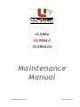
1
UL39Oi UL39OiS UL39OiSA Maintenance Manual MM 390A01 Revision No: 2 Date: 2014-09-15 ULPOWER Maintenance Manual UL390i UL390iS UL390iSA Preface Thank you for deciding to use a ULPower engine. Before carrying out maintenance work on the engine, carefully read the Maintenance Manual. If any passages of the manual are not completely understood or in case of questions, please contact a ULPower authorised dealer. Remarks The figures in this manual show the typical construction. They may not represent in full detail or the exact shape of the parts which have the same or similar function. In addition to this Maintenance Manual, please also refer to the Operating Manual Modifications The information and components/system descriptions contained in this Installation Manual are correct at the time of publication. ULPower, however, maintains a policy of continuous improvement of its products without imposing upon itself any obligation to install them on its products previously manufactured. ULPower reserves the right at any time to discontinue or change specifications, designs, features, models or equipment without incurring obligation. Engine serial number On all enquiries or spare parts orders, always indicate the engine serial number, as the manufacturer makes modifications to the engine for further development. The engine serial number is located on the left side of the crankcase (near the front of the engine). Repeating symbols This manual uses the following symbols to emphasize particular information. These indications are important and must be respected. WARNING : Identifies an instruction which, if not followed, may cause serious injury including the possibility of death. Attention : Denotes an instruction which, if not followed, may severely damage the engine or other components. Note : Indicates supplementary information which may be needed to fully complete or understand an instruction. MM 390A01 Revision No: 2 Date: 2014-09-15 Page: 1 of 18 ULPOWER Maintenance Manual UL390i UL390iS UL390iSA Safety information This manual has been prepared as a guide to correctly service and maintain the UL390 aircraft engine. Keep an engine log and respect engine and aircraft maintenance schedules. Keep the engine in top operating condition at all times. Do not operate any aircraft which is not properly maintained or has engine operating irregularities which have not been corrected. Spare parts must meet with the requirements defined by the engine manufacturer. This is only warranted by use of genuine ULPower spare parts and/or accessories. They are available at the authorized ULPower distribution- and service partners. The use of anything other than genuine ULPower spare parts and/or accessories will render any warranty relating to this engine null and void. Please use proper hand tools and/or special service tools. Torque wrench tightening specifications must be strictly adhered to. Locking devices must be installed or replaced with new ones, where specified. If the efficiency of a locking device is impaired, it must be renewed. It is your responsibility to be completely familiar with the safety instructions including warnings and cautions described in this manual. These warnings and cautions advise of specific operating and servicing methods that, if not observed, can cause a serious engine malfunction or cause the engine to loose power in flight which can result in loss of life, injury or damage to equipment. It is, however, important to understand that the warnings and cautions are not exhaustive. ULPower could not possibly know, evaluate and advise the user of all conceivable ways in which service might be done or if the possible hazardous consequences of each way. Consequently, Although the mere reading of such information does not eliminate the hazard, your understanding of the information will promote its correct use. Always use common shop safety practice. This information relates to the preparation and use of ULPower aircraft engines and has been utilized safely and effectively by ULPower. However, ULPower disclaims liability for all damage and/or injuries resulting from the improper use of the contents. We strongly recommend that any service be carried out and/or verified by a highly skilled professional mechanic. The maintenance functions detailed in this manual are to be considered as average (light) maintenance. Repairs beyond these levels are not recommended as maintenance functions and should be done by authorized overhaul facilities. MM 390A01 Revision No: 2 Date: 2014-09-15 Page: 2 of 18 Maintenance Manual ULPOWER UL390i UL390iS UL390iSA Table of contents Preface ..................................................................................................................1 Remarks ............................................................................................................... 1 Modifications ......................................................................................................... 1 Engine serial number ............................................................................................... 1 Repeating symbols .................................................................................................. 1 Safety information ....................................................................................................2 Table of contents .....................................................................................................3 General ..................................................................................................................4 Authorized Personnel ............................................................................................... 4 Procedure Notes ..................................................................................................... 4 Standard limited engine warranty & warranty conditions ................................................... 5 Time Limits .............................................................................................................6 General note ......................................................................................................... 6 Time limits for engine operation ................................................................................. 6 Time limits for rubber parts ...................................................................................... 6 Annual inspection ................................................................................................... 7 Scheduled maintenance checks ...................................................................................8 General note ......................................................................................................... 8 Maintenance schedule procedures ............................................................................... 8 Inspection Sheet / Maintenance Schedule ...................................................................... 9 Identification......................................................................................................9 Maintenance Schedule ......................................................................................... 10 Engine back to operation ..................................................................................... 12 Maintenance tasks .................................................................................................. 13 General Note ....................................................................................................... 13 Rocker Tappet Clearance ........................................................................................ 13 Cleaning air filter ................................................................................................. 13 Cylinder head bolts torque ...................................................................................... 14 Removal/change of spark plugs ................................................................................ 14 Idle speed adjustment ........................................................................................... 14 Compression test .................................................................................................. 17 MM 390A01 Revision No: 2 Date: 2014-09-15 Page: 3 of 18 Maintenance Manual ULPOWER UL390i UL390iS UL390iSA General Authorized Personnel It is a requirement that every organization or individual possesses the required special tooling, training or experience to perform all tasks outlined. Any task outlined herein may be performed if the organization or individual has met the following conditions: Requisite knowledge of the task through: Experience in performing the task Formal instruction from a ULPower authorized training facility or "on-the-job" instruction by a ULPower or authorized ULPower distributor representative. Suitable work environment to prevent contamination or damage to engine parts. Suitable tools and fixtures as outlined in the Maintenance Manual. Reasonable and prudent maintenance practices are utilized. Requirements of the applicable regulatory authority regarding maintenance procedures are met. Maintenance organizations and individuals are encouraged to contact ULPower throughout its distribution network for information and guidance on any task outlined herein. Procedure Notes Prior to maintenance or service work, make absolutely sure to comply with the stated safety instructions. Principally ensure the following at each maintenance event: Ignition "OFF" Disconnect battery Secure engine against unintentional operation. At maintenance work which requires ignition "ON" and battery connected, take care of the following: Secure the propeller against unintentional turning by hand Secure and observe propeller zone. WARNING: These precautionary measures serve to avoid any injuries in case of an unintentional start of the engine. Non-compliance can result in injuries or death. At maintenance of lubricating and fuel system take care without fail that no contamination, metal chips, foreign material and/or dirt enters the system. WARNING: Always allow engine to cool down to outside air temperature before start of any work. Severe burn and scalds may result if this is not respected. Before re-using parts, clean, check and refit them as per instructions. Before each re-assembly check units for any missing parts. Attention: Strictly observe the tightening torques for screws and nuts. Over or under tightening could cause severe engine damage. If during disassembling/reassembling the removal of a safety item (e.g. Self-locking faster) should be necessary, it must always be replaced by a new one. Use clean screws and nuts only and inspect face of nuts and the thread for damage. If in doubt, use new screws and nuts. At reassembly of the engine, replace all sealing rings, gaskets, securing elements, o-rings and oilseals. At disassembly of the engine, mark the components as necessary to avoid any mix-up. Take care of the markings; do not remove them prior to re-assembly. MM 390A01 Revision No: 2 Date: 2014-09-15 Page: 4 of 18 Maintenance Manual ULPOWER UL390i UL390iS UL390iSA Standard limited engine warranty & warranty conditions PERIOD ULPower Aero Engines, as manufacturer, warrants every ULPower non-certified aircraft engine, sold as new and delivered by an authorised ULPower distributor/reseller, to be free from defects in material and workmanship for a period of 24 months from the date of shipment from the ULPower factory facilities. Replacement of any engine, accessory or part under the warranties will not create a new warranty period or extend the period of coverage. But any engine, part or accessory so repaired or replaced will be warranted for the remainder of the original warranty period applicable to the engine, accessory or part repaired or replaced. WARRANTY CLAIM The warranties are also VOID on any engine or accessory if a gear reduction or other power transmission device (including propeller flange extensions) not designed or approved in writing by ULPower has been used. The warranties do not include reimbursement for normal maintenance expenses or for incidental expenses such as but not limited to, mounting and dismounting of the engine from the aircraft, loss of use, transportation, towing, communication costs, taxis, hotels, food or any other incidental or consequential damage. DISCLAIMER Written notice of any warranty claim must be submitted to ULPower within fifteen (15) days of a suspected defect in material or workmanship and the engine, accessory or part must be made available for ULPower's inspection within thirty (30) days after the claim has been made. To evaluate a claim, following items must also be made available: invoice delivered to the customer as proof of date of purchase/delivery. engine log book showing engine time and all maintenance performed signed and dated inspection/maintenance sheets. ULPower reserves the right not to accept any claim not submitted in accordance with these requirements. TERMS AND CONDITIONS The LIMITED WARRANTIES cover all parts and labour on engines and accessories subjected to normal use and operated and maintained in strict accordance with the corresponding Operating and Maintenance Manuals. All maintenance must be immediately noted, dated and signed in engine logbook when maintenance is performed or the warranties are VOID. Warranty service may be accomplished ONLY AFTER PRIOR WRITTEN APPROVAL from ULPower. ULPower retains the right to repair and/or replace any parts or accessories required for warranty service. All parts replaced under warranty become the property of ULPower. The warranties are VOID on any engine or accessory, disassembled, opened, repaired or altered without the prior written approval of ULPower. The warranties are also VOID on any engine or accessory which has been operated contrary to corresponding Installation, Operating and Maintenance procedures or which in MM 390A01 Revision No: 2 ULPower's sole opinion has been subjected to misuse, neglect, improper installation, corrosion, foreign material ingestion, accident, the use of improper oil, fuel or non genuine ULPower replacement parts. ULPOWER'S EXPRESS WARRANTEES AND THE REMEDIES THEREUNDER ARE EXCLUSIVE AND GIVEN IN PLACE OF (a) ALL OTHER WARRANTIES, EXPRESS, IMPLIED, OR STATUTORY, WHETHER WRITTEN OR ORAL, INCLUDING, BUT NOT LIMITED TO, ANY WARRANTY OF MERCHANTABILITY, FITNESS OR PARTICULAR PURPOSE, OR IMPLIED WARRANTY ARRISING FROM PERFORMANCE, COURSE OF DEALING OR USAGE OF TRADE AND (b) ALL OTHER OBLIGATIONS, LIABILITIES, RIGHTS, CLAIMS OR REMEDIES, EXPRESS OR IMPLIED, ARISING BY LAW OR OTHERWISE, INCLUDING BUT NOT LIMITED TO ANY RIGHT OR REMEDIES IN CONTRACT, TORT, STRICT LIABILITY OR ARISING FROM ULPOWER'S NEGLIGENCE, ACTUAL OR IMPUTTED. ULPOWER'S OBLIGATIONS AND PURCHASER'S REMEDIES UNDER ULPOWER'S EXPRESS WARRANTIES ARE LIMITED TO ULPOWER'S CHOICE OF REFUND, REPAIR OR REPLACEMENT ON AN EXCHANGE BASIS AND EXCLUDE LIABILITY FOR INCIDENTAL, SPECIAL, CONSEQUENTIAL OR ANY OTHER DAMAGES, INCLUDING WITHOUT LIMITATION, ANY LIABILITY OF CUSTOMER TO A THIRD PARTY OR FOR ECONOMIC LOSS, REPLACEMENT COST, COST OF CAPITAL, LOST REVENUE, LOST PROFITS, OR LOSS OF USE OF OR DAMAGE TO AN AIRCRAFT, ENGINE, COMPONENT OR OTHER PROPERTY AND IN NO EVENT WILL ULPOWER'S LIABILITY EXCEED THE ORIGINAL COST OF THE ENGINE OR ACCESSORY. These LIMITED WARRANTIES are the only warranties offered by ULPower. No agreement varying these warranties or ULPower's obligations under them will be binding on ULPower unless made in writing by a duly authorised representative of ULPower and accepted in writing by ULPower. ULPower will not process or honour warranty claims on delinquent accounts. Effective as of August 19th , 2013 Date: 2014-09-15 Page: 5 of 18 ULPOWER Maintenance Manual UL390i UL390iS UL390iSA Time Limits General note These checks, related to limited periods of operation, are planned to help avoid engine troubles by the use of preventive maintenance. Time limits for engine operation The time limits for engine operation will be specified by the TBO (Time Before Overhaul). After reaching this time limit the engine should be shipped to an authorized ULPower overhaul facility. For an overhaul, the engine must be removed from the aircraft, be cleaned, preserved and all openings to be closed to prevent entering of contaminants. Attention: A general overhaul is due after a defined period of operation or after a specified calendar life since initial start of operation (whichever comes first). Engine Type description Engines affected engine S/N TBO Time Between Overhaul UL390i / UL390iSA all 1500 h or 8 years, whichever comes first UL390iSA all 250 h or 4 years whichever comes first * * This do not mean that the engine needs a complete overhaul. However it is necessary to do a complete check up in the ULPower factory. Because of inverted flying, it is possible that certain components were not temporally greased. Find out if there is some earlier “use” of components is necessary. The shipment to an authorized ULPower overhaul facility must include the following: Engine log book Maintenance records of the engine (i.e. all maintenance check lists, and reports of operation, of maintenance, of findings and of oil analyses). The engine and ECU. Statement of total period of operation (TSN – Time Since New) and if applicable the period of operation after a conducted general overhaul (TSO – Time Since Overhaul). Data about the type of aircraft and propeller used Useful remarks and observations concerning the engine. Time limits for rubber parts Every six years the following components must be renewed: Venting and return hose between breather and oil/air separator Engine mount rubbers All fuel lines Oil lines to/from oil cooler MM 390A01 Revision No: 2 Date: 2014-09-15 Page: 6 of 18 Maintenance Manual ULPOWER UL390i UL390iS UL390iSA Annual inspection Perform a 100hr. check at intervals of 100 hours of operation or once every 12 months, whichever comes first. Every second year the 200 hour check should be performed. MM 390A01 Revision No: 2 Date: 2014-09-15 Page: 7 of 18 ULPOWER Maintenance Manual UL390i UL390iS UL390iSA Scheduled maintenance checks General note This chapter lists the periodic inspections which must be carried out after specified periods of operation. Periodic inspections are those that must be performed at 50, 100 and 200 hour intervals in accordance with the maintenance schedule (see further). Additionally a 15 hr. inspection must be performed at 15 hours of operation of a new or overhauled engine. Maintenance schedule procedures All stated checks are visual inspections for damage and wear, unless otherwise stated. All listed work must be carried out within the specified period. For all the maintenance work an allowance of ±10hr. or 30days will be granted but these tolerances must not be exceeded. This means that if for instance after a 100hr. check actually carried out at 110hr. the next check is due at 200hr. ±10hr. and not at 220hr. ±10hr. If a maintenance check is performed before the prescribed interval, the next check is to be done at the same interval (e.g. if first 100hr. check is done at 87 hours, the next 100hr. check has to be done at 187 hours ±10hr. or 1 year later; whichever comes first). Checks are carried out as per the maintenance schedule where type and volume of the maintenance work is outlined in key words. The Inspection Sheet/ Maintenance Schedule must be filled out at each maintenance event. For copies please contact a ULPower representative. All pages of the maintenance check list must be marked with the respective check (e.g. 100hr. check) on the top of the list. All of the maintenance carried out must be initialled in the "signature" area by the performing aircraft mechanic. After maintenance, checks must be entered in the maintenance records. The maintenance must be confirmed in the log book. All discrepancies and repairs must be recorded in a report of findings to be generated and maintained by aircraft owners. Replacement of equipment (e.g. fuel pump, filters, etc.) has to be entered into the engine log book stating TSN and date. MM 390A01 Revision No: 2 Date: 2014-09-15 Page: 8 of 18 ULPOWER Maintenance Manual UL390i UL390iS UL390iSA Inspection Sheet / Maintenance Schedule Identification AIRCRAFT Registration number Aircraft Make Aircraft model and S/N TSN (Time Since New) Propeller make Propeller model and S/N _______________________________ _______________________________ _______________________________ _______________________________ _______________________________ _______________________________ ENGINE Engine type Engine S/N TSN (Time Since New) TSO (Time Since Overhaul) Type of oil used Type of fuel used _______________________________ _______________________________ _______________________________ _______________________________ _______________________________ _______________________________ AIRCRAFT OERATOR Name Contact Address Tel / Fax E-mail _______________________________ _______________________________ _______________________________ _______________________________ _______________________________ _______________________________ _______________________________ MAINTENANCE FACILITY Maintenance work shop Address Tel / Fax E-mail This check is applicable (circle one) _______________________________ _______________________________ _______________________________ _______________________________ _______________________________ _______________________________ 5* 15h* 50h 100h 200h 600h *Shaded column for first 5 and 15 hr. only (from new or overhauled engine) MM 390A01 Revision No: 2 Date: 2014-09-15 Page: 9 of 18 ULPOWER Maintenance Manual UL390i UL390iS UL390iSA Maintenance Schedule Perform the following inspection tasks at the intervals shown. Some tasks are explained under chapter "Maintenance tasks" (see further). Legend: X Blank = do the task = no task required Check (hr.) Inspection Items 5 15 50 100 200 a) General inspection of the engine for damage and abnormalities, including obstructions, cracks, wear and condition of cooling air ducts, baffling and cylinder cooling. Take note of changes caused by temperature. X X X X b) Thoroughly inspect engine for missing or loose bolts, nuts, pins, etc. Replace as necessary. X X X X c) Inspection of all temperature and pressure sensors. X X X X d) Inspection of all oil lines for damage, including leakage, hardening from heat, porosity, loose connections and secure attachments. Verify routing for kinks and restrictions like restricted elbows. X X X X e) Inspect all fuel lines, filters, injectors and pressure regulator for damage, including leakage, hardening from heat, porosity, loose connections and secure attachments. Verify routing for kinks and restrictions like restricted elbows. X X X X f) Verify the complete electrical wiring system including tight fit of connectors, damage and wear. X X X X g) Check exhaust system for cracks (especially when cabin heating is taken from around the exhaust). X X X X X X X X X X X X X X X Signature Visual inspection of the engine Verification of engine suspension a) Inspect engine mounts, dampers and fasteners for secure fit, including damage from heat, deformation, cracks. Replace as necessary. Engine external parts a) Inspect attachment screws and nuts of all external parts for security and fit. Inspect safety wiring. Replace as necessary. ECU a) - disconnect connector from ECU - check the contacts ECU-side and connector side - be sure they are clean and there is no oxidation - replace both if necessary - connect the connector to the ECU Propeller Flange a) check the torque of the propeller flange bolt: must be 300 Nm MM 390A01 Revision No: 2 Date: 2014-09-15 X X Page: 10 of 18 ULPOWER Maintenance Manual UL390i UL390iS UL390iSA Check (hr.) Inspection Items 5 15 50 100 200 Signature Oil level a) Remove drain plug from bottom of oil sump. Drain old oil and inspect for foreign particles. X X X b) Replace copper sealing washers of drain plug and refit to oil sump. X X X c) Refill oil sump with approx. 4 litres of oil. For correct type of oil, refer to Operating Manual. X X X d) Inspect oil level and add oil as necessary to maximum mark. For correct type of oil, refer to Operating Manual. X X X X X X X X X X X Quantity of oil added : ________ litres Oil filter a) Remove oil filter from engine and install new oil filter. Lubricate mating sealing ring of new oil filter with engine oil. Screw on new filter by hand. Air filter a) Inspection of the air filter. Clean/replace as necessary. b) Replace air filter. X Fuel filters a) Remove all fuel filters from aircraft and install new ones. X Cylinder heads a) Check torque of cylinder head bolts. Re-torque as necessary (36Nm) – Do not loosen first. X X X Cylinder heads to be re-torqued : 1 / 2 / 3 / 4 / 5 / 6 Rocker tappet a) Check tappet-valve clearance and adjust as necessary (0.15mm ±0.05mm cold inlet and exhaust) (0.006in ±0.002in) Circle tappet in need of adjustment + mark clearance before adjustment: X X X X X X X X IN1: _______ EX1: _______ IN2: _______ EX2: _______ IN3: _______ EX3: _______ IN4: _______ EX4: _______ IN5: _______ EX5: _______ IN6: _______ EX6: _______ Throttle valve a) Inspect free movement of throttle lever. Inspect that throttle cable allows full travel of throttle lever. a) Inspect throttle cable. Replace as necessary. X Spark plugs a) Renewal of spark plugs. MM 390A01 Revision No: 2 X Date: 2014-09-15 Page: 11 of 18 ULPOWER Maintenance Manual UL390i UL390iS UL390iSA Check (hr.) Inspection Items 5 15 50 X X Signature 100 200 Spark plug connectors a) Verify security of connectors on both spark plug and ignition coils. X X Check of compression a) Inspect compression by differential pressure method. Test pressure = ______ bar (psi) Pressure drop cyl.1 ________ cyl.2 ________ (% or fraction) cyl.3 ________ cyl.4 ________ cyl.3 ________ cyl.4 ________ X Engine test run X X X X X X X X b) After engine test run, if replaced, retighten oil-filter by hand X X X X c) After engine test run, inspect oil level and add oil as necessary to maximum mark. X X X X X X X X X X X X a) Start the engine and run to operating temperature. Smoothly apply throttle to full power. Check temperatures and pressures are within limits Record oil pressure: ________ bar Record fuel pressure: ________ bar Record engine speed: ________ rpm Bring engine to idle speed. Record engine speed: ________ rpm d) After engine test run, adjust idle speed lever position if necessary Record new engine idle speed: ________ rpm General note a) All service instructions and service bulletins are complied with. Engine back to operation All the stated checks or listed work has been carried out as to the recommendations of the engine manufacturer and was recorded in the engine log book. Next check due at : ____________________ hr. (TS___) (engine hours) or before date ____________________ Name ________________ MM 390A01 Revision No: 2 Location Signature __________________ ___________________ Date: 2014-09-15 Date _____________ Page: 12 of 18 ULPOWER Maintenance Manual UL390i UL390iS UL390iSA Maintenance tasks General Note This chapter serves solely for supplement and detailed explanation of some points from the Maintenance Schedule. Rocker Tappet Clearance Unscrew all valve covers (1) with a 4mm Allen Key. Verify rocker tappets have had proper lubrication. Look out for colour changes that could indicate bad lubrication or over heating. Carefully turn propeller until both rocker arms from cylinder 2 are “tumbling”. In this situation, rocker arms from cylinder 1 are in neutral position. ( neither pushed in ). Start with tappets from cylinder 1. Check tappet clearance by inserting a feeler gauge in between the rocker tappet and valve stem (2). Both cold inlet and exhaust tappet clearance should be 0.15±0.05mm (0.0059±0.0020inch). To adjust tappet clearance, loosen nut (3) with a 13mm Spanner. Turn tappet adjusting screw (4) with a 5mm Allen Key. Tighten nut (3) to 20 Nm (14.7 ft lbs) whilst holding Allen Key in place to prevent adjusting screw from turning. Note: After tightening the nut (3), recheck the tappet clearance to make sure adjustment is ok. 2 1 5 4 3 After checking/adjusting tappet clearance cylinder 1, turn the propeller half a turn (180°) anticlockwise (standing in front of propeller) until both rocker arms from cylinder 1 are tumbling and adjust tappet clearance from cylinder 2. Do the same procedure for cylinder 3, 4, 5 and 6 Attention: Continued operation with incorrectly adjusted tappets can result in severe damage to the engine. Before closing valve covers beware the o-ring (5) is completely in it’s groove and in the correct position. Tighten valve cover cap screws M5x10mm to 6 Nm (4.5 ft lbs). Attention: When same tappets are in need of adjustment every time maintenance is performed, complete valve train should be checked for abnormal wear. Also check for proper lubrication and clogged oil lines. Cleaning air filter Inspect air filter according to maintenance schedule. Clean dirty filter as follows: Lightly tap and brush off surface dirt. Spray filter cleaner onto entire element and let soak for approx. 10 min. Rince filter with low pressure water from inside to outside and let element dry naturally. Note: Never use gasoline, steam, caustic liquids, detergents or high pressure cleaning. Attention: A dirty air filter will not only reduce the engine performance but might also promote premature wear to the engine. It can also result in an over-rich fuel mixture. WARNING: When used in heavy dust conditions, clean air filter at 25 h intervals accordingly. If filter mat is damaged, replace air filter. MM 390A01 Revision No: 2 Date: 2014-09-15 Page: 13 of 18 ULPOWER Maintenance Manual UL390i UL390iS UL390iSA Cylinder head bolts torque As cylinder head bolts normally don't need re-torqueing, checking torque is only a precautionary safety measure. Therefore it is sufficient to only check the torque of the 4 cylinder head bolts which are easily accessible. If re-torqueing should be necessary, then all bolts need checking. Inlet manifold, valve covers and plug ( n°6 parts catalogue ) shall have to be removed to access the 2 other bolts on the cylinder head. Note: When checking torque, do not loosen first. Removal/change of spark plugs Unplug ignition leads and unscrew spark plugs with 16mm Plug Socket. Note: As in any modern automobile, sparkplugs do normally not need cleaning. Certainly do not use steel or brass brushes for cleaning and never sand blast spark plugs! If you really want to clean spark plugs, use a plastic brush in a solvent. Spark plug consists of 3 electrodes round the core. Electrode gap cannot be changed. Do not try to bend the electrodes! Note: Operation with leaded fuels (e.g. AVGAS 100LL) can result in increased wear of the spark plugs. Reduce renewal intervals accordingly. At replacement only use spark plug type: Bosch FR 5 DTC Attention: Use of incorrect spark plugs may result in ignition problems or electrical disturbance and possible consequential engine damage. Before inserting spark plugs back into cylinder head, apply appropriate anti-seize compound on thread. Screw in spark plugs with fingers to seat; only then use Plug Socket to tighten to 21 Nm. Place back ignition leads; make sure spark plug connectors are secure. Idle speed adjustment The throttle lever stop (1) is factory set to a position that should correspond to a warm engine idle speed of approx. 800 rpm. Attention: The idle speed of the engine should not be less than 700 rpm as rough turning could cause damage to the engine. We recommend a minimum of at least 800 rpm. With a cold engine, user should apply a little throttle so idle speed is at least 1000 rpm during warm-up. Only when engine is at operating temperature, minimum idle speed can be tested/set. WARNING: Adjusting idle speed should always be done while engine and master switch are switched off. WARNING: Take great care when adjusting throttle lever stop as the engine will be hot. If the warm idle speed of the engine is unsatisfactory, adjust as follows: If idle speed is too low: while engine is running apply throttle to the desired engine rpm. Set friction to keep throttle in position and turn off engine. Loosen throttle lever stop screws (3) with a 2.5mm Allan Key and move throttle lever stop (1) towards the left until it touches the throttle lever (2). Tighten throttle lever stop screws (3) to maximum 3 Nm (2.25 ft lbs). If idle speed is too high, firstly verify if throttle lever (2) is completely against the throttle lever stop (1). If not, stops of aircraft throttle system are MM 390A01 Revision No: 2 Date: 2014-09-15 Page: 14 of 18 ULPOWER Maintenance Manual UL390i UL390iS UL390iSA not set correctly. Adjust according to aircraft manual or manufacturer. Otherwise loosen throttle lever stop screws (3) with a 2.5mm Allan Key and move throttle lever stop (1) a few mm towards the right. Tighten throttle lever screws (3) and test engine idle. Idle rpm will probably be too low; readjust as described above. Note: Do not leave throttle lever stop screws (3) loose while engine is running to test idle speed. Propeller flange bolt torque check 1. Unscrew the M6 screw with an allen key dimension 3. 2. Remove the locking plate. Use a M6-bolt to pull out the plate. 3. Attach the propeller flange holder (T063002) to the prop flange with M14 bolts. 4. Torque the bolt to 300 Nm while holding the prop flange. ( right hand thread ) MM 390A01 Revision No: 2 Date: 2014-09-15 Page: 15 of 18 Maintenance Manual ULPOWER UL390i UL390iS UL390iSA 5. Place the locking plate over the hex top of the bolt. Find out if the existing M6 hole in the locking plate correspond with the M6 hole in the flange. If not, move the ring for 60° on the bolt 6. Only when the M6 holes do not correspond: - drill a hole ø5 through the locking plate - cut M6 thread till the button of the hole - replace the hexagon socket screw M6x15 and fix with Loctite 243 - lock the screw again by punching 2 dimples 7. Attention!! It is possible that while running the engine the bolt loose the torque a little bit. Therefore it’s necessary to re-torque the bolt after 10 hours and again after 20 hours. Afterwards, follow maintenance manual. MM 390A01 Revision No: 2 Date: 2014-09-15 Page: 16 of 18 Maintenance Manual ULPOWER UL390i UL390iS UL390iSA Leak test The best practice for testing the compression in a cylinder of an internal combustion engine, is the "differential compression" test. It requires the use of a tester consisting of two separate pressure gauges, a pressure regulator, a calibrated restrictor orifice, and an on/off valve (see schematic drawing). A source of compressed air (a compressor with a storage tank capable of a minimum of 100psi [7 bar]) is required to perform the test. Be sure that the restrictor orifice of the tester is 0.040" [1mm] The leak test should be done after the engine has run to operating temperature. It is important to use exactly the same procedure with each cylinder and each time you check your compression, if your test is to give meaningful and accurate results. It is very important that accurate records are kept of which compression reading was for which cylinder! WARNING: Make sure master switch and ignition are OFF when performing work on the engine. Remove all valve covers, one sparkplug from each cylinder and, for safety, remove each ignition lead from all plugs. Rotate the prop by hand (anticlockwise when standing in front of propeller) until cylinder 2 is exactly on top position while both rocker arms are tumbling. Now cylinder No.1 will be on compression. You can verify this by moving the prop back a quarter turn and then placing your thumb over the spark plug hole and feeling the pressure build-up while bringing the prop back to TDC. Now install the 14mm threaded adaptor (normally supplied with the compression tester) in the spark plug hole of the cylinder to be tested (Cyl.1). WARNING: Be certain that the air shutoff valve is closed and that you have a firm grip on the tip of one blade of the prop before connecting the system to your source of compressed air. Move the prop slightly away from TDC by turning clockwise. Adjust the pressure regulator to about 20 psi and slowly open the air shutoff valve. Carefully rotate the prop in the turning direction (anticlockwise) against the 20 psi pressure towards TDC until you feel a "flat spot" or rapid loss of turning resistance. If you go too fast, back up beyond top dead center and try again. It is critical that you reach TDC with the prop turning in the normal direction of rotation, not while backing the prop up since this would unseat the piston rings. The piston rings must be at the bottom of their lands in the piston with the piston at the top of its travel. Now make sure you have the prop tip securely held. This is a good time to have a second person help you. The air shutoff valve should be open and slowly adjust the pressure regulator to show exactly 80 psi on the pressure regulator gauge. WARNING: Use caution because if you let the prop move in either direction beyond TDC, it will rapidly begin to rotate and hit and severely injure the person who should have been holding it securely. Now gently move the prop tip back and forth, just a tiny amount. Watch the cylinder pressure gauge and take a reading from it at its peak steady pressure. Again, this will be while moving the prop in the normal direction of rotation. Be certain that the regulator pressure gauge is holding precisely 80 psi. You should have a differential pressure reading of between 60 and 78 over 80. Lower pressure regulator and close off air shutoff valve. Disconnect system from cylinder. Turn prop in normal direction half a turn and repeat test with next cylinder in following order (1-4-5-2-3-6). MM 390A01 Revision No: 2 Date: 2014-09-15 Page: 17 of 18 Maintenance Manual ULPOWER UL390i UL390iS UL390iSA You should now have a series of numbers something like this, depending on the condition of the engine: 76/80, 74/80, 73/80 and 75/80. These numbers, hopefully, will be fairly close to each other in magnitude. What are the limits? What constitutes a bad (too low) cylinder? It is generally accepted that a cylinder reading below 60/80 would require removal from service. A single leak test does not necessarily mean anything. No single diagnostic test should ever be used to decide the health of your engine. The key is to do these tests regularly and keep good records of what you see. Compare each test and make your decision based on several tests conducted over a reasonable period of time. If you have an abnormally low cylinder, you should start the engine and run it on the ground or even fly around the pattern once. Test it again. If it is still low, use a length of garden hose as a "stethoscope" and listen at the exhaust of the ailing cylinder. If you hear a hissing escape of compressed air here, you have an exhaust valve that is not seating. Similarly, listen carefully with the "stethoscope" at the intake, throttle/air box. A hissing sound here would indicate leakage under the intake valve. If neither of these areas is leaking significantly, listen at the breather or oil dipstick/filler tube. A leak in this area is indicative of ring blow-by. This could be ring wear, barrel wear or scoring, or all the ring gaps may be lined up. Hissing between cylinder cooling fins is bad news, possibly a cracked cylinder. Valve leakage is the most commonly found cause of a low cylinder. MM 390A01 Revision No: 2 Date: 2014-09-15 Page: 18 of 18