1
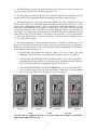
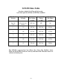
TechNet
Manufactured and Distributed by Even Temp, Inc.
The newsletter for Technical and Warranty issues
SCF-050 Service Manual Addendum
Inside this issue:
This addendum covers the SCF-050 Multi-Fuel Add-On Furnace heating system.
Please read through Section B of the St Croix Service Manual that covers the
Multi-Fuel Burn System. The design of this furnace is based on the Freestanding
St Croix stoves.
Cover Story
SCF-050 Service Manual
Addendum
1/5/10
1
The Electrical Components of this furnace are the same as those shown in section B
with the following exceptions:
1 - This furnace has a different control board.
Control Board Features
How is it different from the
stove version?
Pages 1-2
1
2
2 – The Furnace has a 600-800 CFM Convection Blower
3 –The Furnace has a Fan/Limit Control, which has a dual function. It controls the
Room Air Blower and also acts as the High Limit Switch to shut the unit down if
temperatures rise above 200 Degrees F. in the Plenum area.
Control Board Features
SCF-050 Troubleshooting
Flow Charts
Pages 3-5
Fan/Limit Control
-Replacement
3
6
Feed Rate Adjustments
The Control Board functions slightly differently that the
freestanding stove versions. Please read the following description of the Control Board.
a.
General Operation of the Furnace.
b.
Safety Features, to shut the unit down in the
event the sensors detect a problem in the unit.
The Control Board also has Diagnostic Capabilities to
help in diagnosing 3 areas in the furnace. These areas are:
1. High Temperature Limit.
2. Proof of Fire Sensor
3. Vacuum in the Firebox
Wiring Schematic
7
Parts Layout
Pages 8-10
8
A closer look at the Control Board to the right in figure 1
will explain how the board works. There are five buttons
labeled 1 through 5, a slide switch labeled 6 and a LED
Light bar with 5 Heat Settings. The LED Light bar is also
used during the Diagnostic process, see page 80 for
more details on Diagnostic Features.
The buttons on the board function as follows: (Refer to
Figure 1. The touch pad buttons are labeled with the
white numbers 1 through 5)
SCF-050 Data Table
11
1. The Heat Level button (1) will advance the setting
between level 1 and 5. Once you reach level 5, it will drop
back to level 1. Each level has a LED light to indicate
where the board is set.
Figure 1
-1-
2. The On/Off button (2) turns the Furnace On and Off. It will also reset the board after the
board has sensed a problem and is flashing a Diagnostic code.
3. The Auger button (3) will allow the customer to manually auger fuel into the burn pot on start
up when needed. This is particularly helpful in priming the Auger Tube when it is empty.
4. The Draft Trim button (4) allows for adjusting the Exhaust fan voltage on Heat Level 1 only.
Push the button and the all of the LED Lights in the light bar will flash once (See figure 5). This
decreases the voltage approximately 5 volts below the default setting. Push the button a second
time and all of the LED Lights in the light bar will flash twice. (See figure 5) This increases the
voltage approximately 5 volts above the default setting. Pushing the button a 3rd time will reset
the voltage to the default setting. This adjustment is available to fine tune the #1 Heat Level draft
setting. This would only be used in the case the furnace was hooked up to a tall Vertical Chimney
(to decrease the draft if needed) or if it was connected to a Chimney with a long Horizontal run
(to increase the draft if needed).
5. The Feed Trim button (5) will allow the Fuel feed rate to be adjusted on Heat Level 1 only.
Heat Level 1 should be seen as the Pilot setting of the furnace, when operating on a Thermostat.
Pushing the Feed Trim button (5) will switch between the different adjustments. Heat Level one
can be adjusted in the following ways:
a. The first LED only indicates the Normal #1 setting. (2.5 second on time). This is the
highest Pilot setting and may be used when heating a larger size home. (See figure 2)
b. The first and fourth LED lights indicate the #1 Low setting. (2.0 second on time) This is
the medium Pilot setting and may be used when heating a medium size home where less
heat is needed when the unit is running in pilot mode. (See figure 3)
c. The first and fifth LED lights indicate the #1 High setting. (1.50 second on time) This is
the lowest Pilot setting and may be used when heating a small size home where minimal
heat is needed when the unit is running in pilot mode. (See figure 4)
Figure 2
Figure 3
Figure 4
Figure 5
The adjustments described in points 4 and 5 remain in effect as long as the unit is plugged
in. If the unit gets unplugged or if there is a power failure the settings are lost and the
adjustments would need to be reset.
-2-
Troubleshooting Flow Charts for the SCF-050
The Trouble shooting Flow Charts for the following components will be referenced from
Section B of this Service Manual to eliminate duplicating the charts:
Digital Control Board
Please refer to page 100 of the original Digital Control Board Service Manual.
Combustion Blower
Please refer to page 103 of the original Digital Control Board Service Manual.
Vacuum Switch
Please refer to page 103 of the original Digital Control Board Service Manual.
Proof of Fire Switch
Please refer to page 106 of the original Digital Control Board Service Manual.
Troubleshooting Flow Charts
Convection Blower
The Convection Blower in the SCF-050 is a 2-speed Blower. The Low speed is 600 CFM
and the High speed is 800 CFM. The Blower runs with the aid of a Capacitor. The
Fan/Limit Control controls the Blower. The Fan/Limit Control has adjustable settings to
operate the blower at different temperature settings.
NOTE: A Blower problem can sometimes be traced back to loose wiring connections
at the Capacitor. Check the brown wires that are connected to the Capacitor for
loose connections. Use caution when handling Capacitors.
-3-
Fan/Limit Control
The Fan/Limit Control shuts the furnace down in an Over-Temp situation. This usually
involves the room air fan. The fan may be defective or the fan may need cleaning. If the
squirrel cage becomes dirty, they can’t move enough air to keep the furnace cool enough
when running on the higher settings. If the High Limit trips more than once a closer look
should be given to Convection Blower of the furnace. The Fan/Limit Control may
actually be causing the problem if it is not controlling the fan correctly. The control is
adjustable and the settings should be looked at when troubleshooting this area. Setting the
Limit setting too low could cause the unit to shut down at the incorrect temperature.
NOTE: The Room Air Fan (Convection Blower) is wired independently from the
Control Board. Keep in mind when troubleshooting this area of the furnace that
replacing the Control Board will not fix any issues related to the Blower and
Fan/Limit Control.
NOTE: A dirty Filter may cause the furnace to run hotter and may contribute to the
unit shutting down. Check the filter and replace if needed.
-4-
Auger Motor - Electrical
Remember: Checking for Voltage either at the Harness or directly at the Pin-Out of the
control board can only be done when the Auger should be running. The auger runs for 2
minutes during the Start-Up Cycle or runs at a #1 level 5 minutes after the stove is first
turned on. Hot-wiring the fan direct with a power cord is also a good way to check the
Auger motor.
Auger Motor – Mechanical
-5-
Fan/Limit Control - Replacement
Before installing the new Fan/Limit
Control, be sure to remove the BreakAway tab between the left and right wiring
circuits. See figure 6 to the left. After
replacing
the
Fan/Limit
Control,
remember to adjust the Fan ON and the
Fan OFF settings. Failure to adjust these
settings may cause the Blower to short
cycle.
Figure 6
Feed Rate Adjustment
The Default Cycle Time is 10.0
seconds. Please see figure 7 to the left.
The 10.0-second cycle can be changed
to 8.5 seconds by placing the jumper on
the 2 pins to the Right. This should
only be done if the fuel used feeds
slowly, such as long Pellets or Cherry
Pits.
Use Caution when switching to a
shorter Cycle Time. If the pot
overloads using a shorter Cycle
Time, set the board back to a Longer
Cycle Time.
Certain fuels (Mainly Corn and Small
Grains) tend to feed faster and may
need to be slowed down. Placing the
jumper on the 2 Center Pins will
change the Cycle Time to 11.5 seconds.
Figure 7
-6-
SCF-050 Wiring Schematic
The Electrical Rating of this furnace is: 120 Volt, 60 Hz, 4 AMP. The minimum
recommended circuit is 15 Amp. A dedicated circuit for the furnace is recommended.
-7-
SCF-050 Parts Lay-out
-8-
#
1
2
3
4
5
6
7
8
9
10
11
12
13
14
15
16
17
18
19
20
21
22
23
24
25
26
27
28
29
30
31
32
33
34
35
36
37
38
39
40
41
42
43
44
45
PART NUMBER
80P53707-R
80P53677-R
80P53797-R
80P20132-R
80P53798-R
80P30162-R
80P52592-R
80P53623-R
80P52568-R
80P53619-R
80P2001-R
80P30144-R
80P30089-R
80P30102-R
80P30085-R
80P53835-R
80P30207-R
80P30045-R
80P30205-R
80P30147-R
80P30169-R
80P53813-R
54995K24-R
80P30658-R
80P20168-R
80P52237-R
80P53836 -R
80P53810-R
80P30168-R
80P53843-R
80P30092-R
80P30151-R
80P30206-R
80P30090-R
80P30094-R
80P30142-R
80P30119-R
80P20132-R
80P30143-R
80P30130-R
80P20022-R
80P30125-R
80P20027-R
80P30139-R
80P53795-R
DESCRIPTION
DOOR HANDLE
MOUNT PLATE ASSEMBLY
ASH PAN DOOR - COMPLETE
ASH PAN DOOR GASKET – 42”
ASHPAN
ASH PAN AREA CLEANOUT COVER
SLIDER ROD - UNIVERSAL
POT SLIDER ASSEMBLY
COAL RAKE ROD
COAL RAKE
COMBUSTION FAN
CONVECTION BLOWER
CABINET SIDE LEFT
EXHAUST FAN ACCESS PANEL
BLOWER ACCESS PANEL
CONTROL COVVER ASSEMBLY
ROCKER SWITCH – 2 SPEED BLOWER
SPEAKER TERMINAL - THERMOSTAT
CONTROL BOARD – SCF-050
FAN/LIMIT CONTROL
FAN LIMIT MOUNT BOX
INTAKE DAMPER WELDMENT
2” ALIMINUM HOSE – 22”
VACUUM SWITCH
COMBUSTION FAN GASKET
CLEAN OUT COVER PLATE - FIREBOX
BURN POT WELDMENT
HOPPER - COMPLETE
AUGER ACCESS PLATE
BACK PANEL/FILTER BRACKET ASSEMBLY
CABINET TOP
HOPPER MOUNT GASKET
HEAT EXHANGE BAFFLE
CABINET SIDE - RIGHT
HOT AIR BOX
WATERCOIL ACCESS COVER GASKET
WATERCOIL ACCESS COVER
DOOR GASKET – 40”
DOOR GLASS
GLASS RETAINER
GLASS GASKET – 35”
DOOR FRAME - FIREBOX
SLIDE OUT BOTTOM COVER GASKET – 24”
SLIDE OUT BOTTOM COVER
CABINET FRONT DOOR ASSEMBLY
-9-
#
46
47
48
49
50
51
52
53
54
PART NUMBER
80P20038-R
80P52630-R
80P52957-R
80P20248-R
80P20278-R
80P30191-R
80P20245-R
80P50858-R
80P53807-R
DESCRIPTION
PROOF OF FIRE SWITCH
TERMINAL BLOCK
MOTOR MOUNT BRACKET ASSEMBLY
5/8” COLLAR W/ SETSCREW
AUGER MOTOR
MOTOR RETAINER BRACKET
AUGER GASKET
AUGER BUSHING WASHER
AUGER WELDMENT
- 10 -
SCF-050 Data Table
Based on a default Cycle Time of 10.0 seconds.
Cycle time equals the ON time & OFF Time combined.
Heat Level
Selection
Auger ON
(Seconds)
Combustion
Fan Voltage
+/- 10%
Convection Fan
Voltage
+/- 10%
Corn Fuel
(Lbs./Hour)
+/- 10%
Start-Up
Cycle
Off for the first 5
minutes
100 Volts
OFF
NA
1
2.5
90 Volts
120 Volts
2.0 Lbs.
2
3.0
98 Volts
120 Volts
2.75 Lbs.
3
3.5
105 volts
120 Volts
3.5 Lbs
4
4.0
111 volts
120 Volts
4.35 Lbs.
5
4.5
120 volts
120 Volts
5.20 Lbs.
The SCF-050 is approved for Corn, Wheat, Rye, Cherry Pits, Distiller’s Grain
Pellets and Wood Pellets. Feed rates will vary from fuel to fuel. The above chart is in
reference to burning corn.
- 11 -