1
INSTALLATION & OPERATING
INSTRUCTION MANUAL
owners
manual
MODEL NOS.
3508332
3508732
5008732
5508332
6508732
FOR USE WITH
NATURAL GAS ONLY
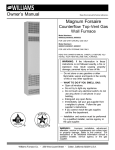
COUNTERFLOW
TOP VENT
GAS WALL FURNACES
READ THIS OWNERS MANUAL
CAREFULLY BEFORE YOU INSTALL
YOUR NEW WILLIAMS WALL FURNACE
WARNING:
If the information
in this
manual is not followed exactly, a fire or explosion
may result causing
property
damage, personal injury or loss of life.
--
MODEL NOS.
3508331
3508731
5008731
5508331
6508731
FOR USE WITH
LIQUEFIED
PETROLEUM
(L.P.)
GAS ONLY
Save This Manual For
Future Reference.
Do not store or use gasoline or other
flammable
vapors and liquids in the
vicinity of this or any other appliance.
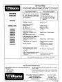
WHAT TO DO IF YOU SMELL GAS
• Open all windows.
• Do not try to light any appliance.
• Do not touch any electrical switch; do
not use any phone in your building.
• Extinguish any open flame.
• Immediately
call your gas supplier
from a neighbor's phone. Follow the
gas supplier's
instructions.
• If you cannot reach your gas supplier,
call the fire department.
Installation
and service must be performed by a qualified installer, service
agency or the gas supplier.
WARNING: Improper installation,
adjustment, alteration, service or maintenance
can cause injury or property damage.
Refer to this manual. For assistance or
additional information consult a qualified
installer,
service
agency
or the gas
supplier.
WARNING: Do not install any of these fur- I
naces (Natural
or L.R Gas) in mobile
homes, trailers, or recreational vehicles.
I
ALL MODELS
ARE CERTIFIED
FOR USE
CANADA EXCEPT 6508731 AND 6508732.
IN
Williams Furnace Co., 225 Acacia St., Colton, CA 92324, USA
PRINTED
IN U.S.A
6/98
P321005
Contents
Your Williams Warranty .........................
Introduction ..................................
Basic Description ..............................
Optional Accessories ...........................
Helpful Installation Information ...................
Safety Rules .................................
Unpack Your Furnace ..........................
Basic Tools Needed ............................
Basic Materials ...............................
Installing Your Wall Furnace .....................
Locating Wall Furnace and Thermostat ..........
Combustion and Ventilation Air ................
Installation
Recessed Mount Installation .............
Surface Mount Installation ................
Vent Installation ........................
Mounting Your Furnace .....................
Gas Supply and Piping ......................
Electrical Wiring ...........................
Thermostat Installation ......................
Optional Accessory Installation ...............
Start Up Procedure ...........................
Operating Your Furnace .....................
How To Care For Your Furnace ...............
Furnace Technical Information ..................
TROUBLESHOOTING
CHART ...............
Wiring Diagrams ...........................
Repair Parts ..............................
SERVICE HINTS ......................
How To Order Repair Parts .............
2
3
3
3
3
4
5
5
5
6
6-7
7-10
10-12
12-13
13-15
15-17
17-18
18-19
20-21
21-23
24
25-30
31-32
32
33-36
37-38
39-46
Back Cover
Back Cover
Your Warranty
The Manufacturer, Williams Furnace Co., warrants this wall furnace or heater to the original purchaser under the following
LIMITED
ONE-YEAR
1. Any part thereof which proves to be defective in material or workmanship within one year from date of original
Manufacturer's
option, FOB its factory,
2. No liability
LIMITED
conditions:
WARRANTY
is assumed
EXTENDED
by the Manufacturer
for removal or installation
labor costs, nor for freight
or delivery
purchase
for use will be repaired or replaced al the
charges.
WARRANTY
1, In addition to the above limited one-year warranty on the complete unit, any heat exchanger which burns out or rusts under normal installation, use and service
conditions during a period of nine years following expiration of the one-year warranty period will be exchanged for a like or functionally similar part.
2. No liability is assumed by the Manufacturer for removal or installation labor costs, nor for freight
or delivery charges
LIMITATIONS
1. THIS LIMITED WARRANTY IS THE ONLY WARRANTY MADE BY THE MANUFACTURER.
IMPLIED WARRANTIES OF MERCHANTABILITY
OR FITNESS FOR
ANY PARTICULAR PURPOSE ARE LIMITED TO THE SAME ONE YEAR TERM AS THIS EXPRESS WARRANTY. UNDER NO CIRCUMSTANCES
SHALL THE
MANUFACTURER BE LIABLE FOR INCIOENTAL, CONSEQUENTIAL,
SPECIAL OR CONTINGENT DAMAGES OR EXPENSES ARISING DIRECTLY OR INDIRECTLY FROM ANY DEFECT IN THE PRODUCT OR ANY COMPONENT
OR FROM THE USE THEREOF THE REMEDIES SET FORTH HEREIN ARE THE EXCLUSIVE
REMEDIES AVAILABLE TO THE USER AND ARE IN LIEU OF ALL OTHER REMEDIES
Some states do not allow limitations on how long an implied warranty lasts, and some states do not allow the exclusion or limitation of incidental
or consequential damages, so the above limitations or exclusions may not appty to you
2. This warranty does not include any charge for labor or installation
3. This warranty does not extend to painted surfaces
nor to damage or defects resulting
from accident, alleration, misuse or abuse, or improper installation.
4 This warranty does not cover claims which do not involve defective workmanship or materials.
DUTIES OF THE CONSUMER
1. The heating equipment must be installed by a qualified installer and operated in accordance with the installation and homeowner's instructions furnished
equipment.
2, Any travel, diagnostic costs, service labor, and labor to repair the defective
3, A bill of sale, cancelled
check, payment record or permit should
4. Have the installer enter the requested
with the
unit will be the responsibility of the owne_
be kept to verify purchase date to establish the warranty period.
information in the space below.
GENERAL
1 The Manufacturer neither assumes nor authorizes any person to assume for it any other obligation or liability in connection with said equipment
2. Service under this warranty should be obtained by contacting your dealer Provide the dealer with the model number, serial number and purchase date verification
3. If. within a reasonable time after contacting your deale_ satisfactory service has not been received,
CA 92324_ for assistance
contact: Customer
4 THIS WARRANTY
RIGHTS WHICH VARY FROM STATE TO STATE
INSTALLATION
Model
Orig.
GIVES YOU SPECIFIC
LEGAL RIGHTS, AND YOU MAY ALSO HAVE OTHER
Service Department, 225 Acacia St., Colton,
INFORMATION
No.
Serial
No
Purchaser
Address
City and State
Zip
Dealer
Address.
City and State
Installation
authorized
Zip
date
representative
local codes.)
Signed
who
certifies
that
this
by
appliance
(Dealer
has
been
installed
in accordance
with
Manufacturer's
instructions
or
and
introduction
Please read our instructions before you install and use your furnace. This will help you obtain the full value from this
furnace. It could help you avoid needless service costs, if the answer to the problem is found within this instruction
manual.
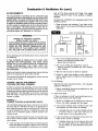
Basic Description
The combustion system draws combustion air directly from
the room in which the furnace is installed, and through ventilation grills or ducts connected to the outdoors, such as an
attic or crawl space. The combustion gases are discharged
through the roof within a listed vent pipe
The furnace heat exchanger is built of heavy gauge steel
treated for corrosion resistance. The fan at the top forces
air down along the front, back and sides of the heat
exchanger where it is discharged into the room. The furnace cabinet is also constructed of heavy gauge steel and
has an enamel paint finish.
Models 3508331; 3508332; 5508331 and 5508332 are
equipped with an electronic ignitionautomatic pilot relight
system.
This appliance is equipped with a vent safety shutoff system designed to protect against improper venting of combustion products. Operation of this wall furnace when not
connected to a properly installed and maintained ventillating system or tampering with the vent safety shutoff system can result in carbon monoxide (CO) poisioning and
possible death.
Your Counterflow Top Vented Wall Furnace is shipped
ready to install on the surface of a wall or recessed up to
9-1/4 inches in a wall, with wall studs spaced 16 inches
center to center.
Vent piping and exhaust are not part of the Williams furnace package and must be purchased separately.
Always consult your local heating or plumbing inspector,
building department or gas utility company regarding
regulations, codes or ordinances which apply to the installation of a counterflow top vented wall furnace.
Air is drawn in at the top by the fan and discharges through
a grille near the floor. A two-speed fan is used with Model
50087;55083 and 65087 series. A single speed fan is used on all other models. The furnace contains a multi-slot
burner (two on Model 50087; 55083 and 65087 series) and
burns either Natural or L.P (Liquefied Petroleum) Gas,
depending on the model you have purchased.
The furnace controls are located behind an access door
on the lower front of the furnace. All models are equipped
with American Gas Association listed gas valves and pilots.
Optional
Accessories
TRIM STRIP KIT 4701
Provides finished edge at sides of wall furnace. Neutral
beige enamel painted steel.
OUTLET GRILLE REGISTER 6701 pg. 21 & 22
Lets you route some heated air to a second room. Mounts
on side wall of second room and must be within 10 inches
of wall furnace.
OVAL VENT KIT 9901
This U.L. listed B/W vent kit contains 4 feet of oval doublewalled vent pipe, plate spacers and starter or hold-down
plate that starts the venting from the top of furnace. See
page 13 for additional items you will need.
DIFFUSER GRILLE KIT 6703 Fig. 3, pg. 7
Lets you route some heated air in a two-way direction. Kit
6704 for one-way direction.
REAR OUTLET KIT 6801
Lets you route some heated air to a second room behind
the furnace. Finished wall of second room must be within
10 inches of furnace. Ref. Fig. D, pg. 7. Built-in damper
lets you shut off air flow to second room if desired.
SHORT REAR OUTLET KIT 6802
Lets you route some heated air to a second room behind
the furnace when furnace is recessed mounted. Finished
wall cannot be more than 3/4 inches from rear of furnace.
Built-in damper lets you control the air flow to the second
room.
Helpful
Installation
VENT ENCLOSURE KITS 9812 or 9824
These kits are used only when the furnace is surface
mounted. They enclose the vent pipe from the top of the
surface to the ceiling.
SIDE GRILLE KIT 6702
Allows you to direct heated air from the side of furnace
into the same room.
NOTE
All kits are identified on the carton by their Manufacturing
Number respectively, 6701, 6703, 6704, 6801, 6802, 4701,
9901, 9812, 9824 and 6702. These numbers are also listed
on the furnace rating plate.
Information
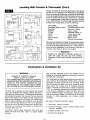
The following booklets will help you in making the installation:
ANSI/NFPA 70-1990 or current edition "National Electrical Code." In Canada: CSA C22.1 Canadian Electrical Code.
American National Standard NFPA54/ANSI Z223.1 1988 or current edition "National
Obtain from -- American
Fuel Gas Code."
National Standards Institute, Inc., 1430 Broadway, New York, N.Y. 10018.
In Canada: CAN/CGA B149 Installation Code.
m:_m
Safety Rules
WARNING
For L.IR gas, the minimum inlet gas supply pressure
for the purpose of input adjustment is 11" water column. The maximum inlet gas supply pressure is 13"
water column.
READ THESE RULES AND THE INSTRUCTIONS
CAREFULLY.
FAILURE TO FOLLOW THESE
RULES AND INSTRUCTIONS COULD CAUSE A
MALFUNCTION OF THE FURNACE. THIS COULD
RESULT IN DEATH, SERIOUS BODILY INJURY,
AND/OR PROPERTY DAMAGE.
INSTALLATION MUST CONFORM TO LOCAL CODES. IN
THE ABSENCE OF LOCAL CODES, INSTALLATION MUST
CONFORM WITH THE NATIONAL FUEL GAS CODE, ANSI
Z223.1. THE APPLIANCE, WHEN INSTALLED, MUST BE
ELECTRICALLY CONNECTED AND GROUNDED
IN
ACCORDANCE WITH LOCAL CODES OR, IN THE
ABSENCE OF LOCAL CODES, WITH THE CURRENT
NATIONAL ELECTRICAL CODE ANSI/NFPA NO. 70.
7. ANY SAFETY SCREEN, GUARD OR PARTS REMOVED FOR SERVICING THIS APPLIANCE MUST
BE REPLACED PRIOR TO OPERATING THE APPLIANCE TO AVOID PROPERTY DAMAGE, BODILY
INJURY OR DEATH.
8.
INSTALL the furnace vent directly to the outdoors, so
that harmful gasses will not collect inside the building.
Follow the venting instructions for your type installation exactly. Use only the type and size of vent pipe
and fittings specified.
9.
BE SURE to provide for adequate combustion and
ventilation air. See page 6. The flow of this air to the
furnace must not be blocked.
IN CANADA
1. INSTALLATION MUST CONFORM TO LOCAL
CODES OR, IN THE ABSENCE OF LOCAL
CODES, THE CURRENT CAN/CGA B149 INSTALLATION CODE.
2. THE APPLIANCE, WHEN INSTALLED, MUST BE
ELECTRICALLY CONNECTED AND GROUNDED IN ACCORDANCE WITH LOCAL CODES OR,
IN THE ABSENCE OF LOCAL CODES, WITH
THE CURRENT CSA C22.1 CANADIAN ELECTRICAL CODE.
3. REFERENCE
IS MADE IN THIS MANUAL
REGARDING GAS TYPE AS L.P.G. BE ADVISED
THAT L.RG. IS NOT AVAILABLE IN CANADA,
REFER TO PROPANE/L.P. GAS.
10. NEVER test for gas leaks with an open flame. Use
soap suds to check all gas connections. This will avoid
the possibility of fire or explosion.
11. ALLOW furnace to cool before servicing. Always shut
off electricity and gas to furnace when working on it.
This will prevent any electrical shocks or burns.
12. DUE TO HIGH TEMPERATURES, locate the furnace
out of traffic and away from furniture and draperies.
13. ALERT children and adults to the hazards of high surface temperature and to keep away to avoid burns or
clothing ignition.
14. CAREFULLY supervise young children when they are
in the same room with the furnace.
1.
USE ONLY MANUFACTURER'S
REPLACEMENT
PARTS. USE OF ANY OTHER PARTS COULD CAUSE
INJURY OR DEATH.
15. DO NOT place clothing or other flammable
on or near furnace.
16. INSTALLATION and REPAIR must be done by a
qualified service person. The appliance should be inspected before use and at least annually by a professional service person. More frequent cleaning may be
required due to excessive lint from carpeting, bedding
material, etc. It is imperative that control compartments, burners and circulating air passages be kept
clean.
DO NOT install this furnace in an alcove.
2,
3_ DO NOT install these furnaces in a travel trailer,
recreational vehicle or mobile home.
4.
MAINTAIN all clearances
specified
in section
"Locating Wall Furnace and Thermostat" and "Vent
Installation."
5.
BE SURE furnace is for type of gas to be used. Check
the rating plate by the gas valve in the lower cabinet.
Do not change it to use other gases. Unsafe operation could result and could cause bodily injury and
death.
17. BEFORE INSTALLING: To avoid electrical shock, turn
off electrical circuits that pass through the wall where
you are going to install the furnace.
18. CAUTION: Label all wires prior to disconnection
when servicing controls. Wiring errors can cause improper and dangerous operation. Verify proper operation after servicing
For Natural gas, the minimum inlet gas supply
pressure for the purpose of input adjustment is 5" column. The maximum inlet gas supply pressure is T'
water column.
6.
I
material
WARNING
DO NOT USE THJS HEATER IF ANY PART HAS BEEN UNDER WATER. IMMEDIATELY CALL A QUALIFIED
SERVICE TECHNICIAN TO INSPECT THE HEATER AND TO REPLACE ANY PART OF THE CONTROL SYSTEM
AND ANY GAS CONTROL WHICH HAS BEEN UNDER WATER.
--4--
I
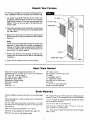
Unpack
Your Furnace
The furnace is shipped in one carton containing the furnace, installation instruction booklet and hardware bag.
1. Lay carton horizontally. Remove top trim cover from
its packing. Remove thumb screw at top of furnace,
raise top front panel 1/2 inch and remove panel from
cabinet. This is so you can get to the electrical connections later.
2. Place these and other parts, as they are removed from
furnace, where they cannot be lost or damaged before
you need them.
3. Bottom front panel can be removed by grasping just
below handle and pulling it outward and then upward.
See Fig. 1.
NOTE
Check the burner rating plate, located in burner compartment, to make sure your furnace is equipped to
operate on the type of gas available (either Natural or
L.IRGas). Do NOT convert unit from Natural Gas to L.IR
Gas or from L.F_ Gas to Natural.
4. Remove all literature and package containing thermostat, wire and metal anchors used for free standing
installation.
5. Check the fan blade to be sure it spins freely.
Basic
Tools
1/8" Allen wrench
Stud Locator or small finish nails
Tin Snips
8" adjustable wrench
12" adjustable wrench
Key hole saw or Sabre saw
Hack saw
2- 10" or 12" pipe wrenches
Gloves and safety glasses
Hand drill or properly grounded electric drill.
Expansion bit 1/2" to 1-5/8" or 1/2" and 1-1/2" blade bits
1/8" and 3/16" drill bit (metal)
6 ft. folding rule or tape measure
Screwdriver (med. blade)
Screwdriver (Phillips head)
Pliers (wire cutting)
Hammer
Hole Saw - 2"
Basic
Materials
Pipe and fittings to make connections to furnace (see page
17).
3/4" Quarter Round or other wood trim molding approximately 16' long or Trim Accessory 4701 is recommended.
Caulking compound - silicone rubber with a temperature
rating of 500°tE
2" x 4" x (length as required) Spacer Blocks (see Close
Off Stud Space, page 12).
DO NOT USE types advertised as paintable or for bath
tub use as most contain fillers and will not withstand high
temperatures.
Pipe Joint Compound
Needed
Oval Vent Kit 9901 is recommended.
Vent Enclosure Kit 9812 or 9824 if furnace is to be surface mounted is recommended.
resistant to L.P. Gases.
1 x 1 wood strips if Optional Side Outlet Grille Register
6701 is used.
Electrical wiring supplies as needed (see page 18).
Minimum wire size is #14 gauge copper.
--5--
Installing
Your Wall Furnace
IMPORTANT
The following steps are needed for proper installation and
safe operation of your furnace. If you have any doubts as
to any requirements, always consult your local Heating or
Plumbing Inspector, Building Department or Gas Utility
Company regarding regulations, codes, or ordinances
which apply to the installation of a vented wall furnace.
Obtain professional help where needed.
For satisfactory and trouble-free operation, be sure to:
1. Properly locate the furnace within the space to be
heated.
2. Install the furnace in accordance with local codes or
ordinances and instructions provided.
3. Maintain minimum clearance: Floor 0 inches or ceiling 4 inches, side wall 4 inches. For exception to
minimum side wall clearance, see Fig. 3, pg. 7.
4. Be sure to provide enough combustion and ventilation
air.
The CHECK AND ADJUSTMENTS on page 24 are vital
to the proper and safe operation of the furnace. Be sure
they are done.
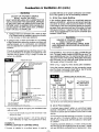
Locating
Wall Furnace
& Thermostat
The top of the furnace must be at least 4 inches from the
ceiling. See Fig. 2.
Consider the following points before attempting to install
the furnace:
With standard furnace discharge outlet, do not install
closer than 4 inches to intersecting wall. See Fig. 3B,
page 7.
CAUTION
Do not make cut-outs in wall or ceiling before checking in the attic for ceiling joist locations and proposed
venting.
When using optional kits 6703 or 6704 maintain clearances
as shown in Figs. 3A or 3C, page 7.
The counterflow vented wall furnaces are shipped ready
to install on the surface of the wall or recessed up to 9-1/4
inches in the wall, with studs 16 inches center-to-center
or stud space can be framed-in to 16 inches, see page
10, Recessed Mounting.
When using optional kit 6704 maintain clearance as shown
in Figs. 3A and 3F, page 7. Use only optional outlet and
grille kits available from manufacturer.
I_[{'kIP_ll
Place the furnace near the center of the space to be
heated for good air circulation. Do not put it behind a door
or draperies.
Do not install the furnace in a closet, alcove, or small
hallway where the furnace could be isolated by closing
doors to the heater space. See Fig. 2 for the minimum
clearances.
Do not install the furnace in a mobile home, trailer, or
recreational vehicle.
The bottom of the furnace may rest directly on a wood or
concrete floor. If floor is other than wood or concrete there
must be a piece of wood or sheet metal under the furnace
that is at least the same size as the bottom of the furnace.
On recessed installations the recessed portion may have
0 inches clearance to combustible material.
To provide adequate clearance and service access the
front of the furnace must face the open room. Be sure that
gas piping and electrical wiring can be brought to the location. See sections covering piping and electrical wiring for
your type of furnace mounting.
FOR EXCEPllONS
TO MIN. SIDE
WALL CLF_CE
_RG.S
,'.'_ k 3F3A. ,.3C
Furnace vent must be installed directly to the outdoors so
that combustion gasses will not collect inside the building.
Provide an adequate vent or flue in accordance with local
codes or ordinances and instructions provided by the vent
pipe manufacturer.
Check the minimum spacing needs as shown in Figs. 2
and 3, pages 6 and 7.
--6--
RNISHED FLOOR
O" MIN.
Locating
Wall Furnace
0
_
I_llM
A
IS USED
GRIU-E
IS
US[D
X
1_4" _
HOT SPOTS:
Concealed pipes or ducts
Fireplaces
Registers
TV sets
Radios
Lamps
Direct sunlight
Kitchen
....,%
A.
3/4 "_-
B.
_
KIT I_01
OP_IONA_
rWO-WA_
REAR GRILLE
2 ¸'_
_.
I
12 ¸' _
12"MIN
WHEN
OPTIONAL
T W0 -WAY
F_ONT
DEFL [CTING
GRILLE
rS USED
D.
C.
FJT 67_
OPTIONAL
WAY f_EAR
ON[GRILLE
_'_
I,_-
3/4
MI%
(Con't)
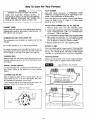
Choose a location for the thermostat about 5 feet above
the floor on an inside wall. The thermostat wire supplied
with your furnace is 20 feet long, which should be enough
to run up through the attic so the thermostat can be a maximum of 16 feet from the furnace measured in a straight
line, or approximately 12 feet from the furnace if the wire
is run under the floor. The thermostat should be sensing
average room temperature, avoid the following:
_/4"MIN
WHEN
OPTIONAL
ONE-WAY
FRONT
DEFLECTING
GRILLE
& Thermostat
COLD SPOTS:
Concealed pipes or ducts
Stairwells - drafts
Doors - drafts
Unheated rooms on
other side of wall
DEAD SPOTS:
Behind doors
Corners, and alcoves
After picking a location that meets the requirements, check
the walls, attic and roof to make sure there are no obstructions such as pipes, electric wiring, etc., which could interfere with the installation of the furnace or vent pipe. If
required, move them or pick a new location.
;_
WARNING
DANGER OF PROPERTY DAMAGE, BODILY INJURY OR LOSS OF LIFE. DO NOT INSTALL
FURNACE IN ANY AREA WHERE OXYGEN IS IN
USE.
_IE-WAy
FRONT
0PTIONAo__
GRILL[
-MI N
r2
E.
Combustion
& Ventilation
WARNING
Air
High humidity, especially during cold weather, may be
damaging to buildings because condensation forms on
windows and inside walls.
DANGER OF PROPERTY DAMAGE,
BODILY INJURY OR DEATH
THE FURNACE AND ANY OTHER FUEL BURNING
APPLIANCE MUST BE PROVIDED WITH ENOUGH
FRESH AIR FOR PROPER COMBUSTION AND
VENTILATION OF FLUE GASES. MOST HOMES
WILL REQUIRE THAT OUTSIDE AIR BE SUPPLIED.
The high cost of energy for home heating has brought
about new materials and methods used to construct or
remodel most current homes. The improved construction
and additional insulation has reduced the heat loss and
made these homes much tighter around windows and
doors so that infiltrated air is minimal. This creates a problem to supply combustion and ventilation air for gas-fired
or other fuel burning appliances. Any use of appliances
that pull air out of the house (clothes dryers, exhaust fans,
fireplaces, etc.) increases this problem and appliances
could be starving for air.
In addition, these energy measures mean that your
home will retain more water vapor or a higher relative
humidity.
The combination of a tight energy efficient home with the
use of exhaust fans, fireplaces, clothes dryers, and gas
appliances results in more and more air being drawn
from the house until fresh air may be sucked in to the
house down the furnace flue or fireplace chimney.
Carbon monoxide can be the result. Carbon monoxide or
"CO" is a colorless, odorless gas produced when fuel
is not burned completely or when the flame does not
receive sufficient oxygen. Automobiles, charcoal, wood
fires and improperly vented or air-starved coal, oil and gas
furnaces or other appliances
can produce carbon
monoxide.
Be aware of these air-starvation
1. Headaches, nausea, dizziness.
2. Excessive humidity - heavily frosted windows, moist
"clammy" sensation.
3. Fireplace smokes, won't draw.
4. Furnace flue backs up.
--7--
signals:
Combustion
& Ventilation
AIR REQUIREMENTS
Air (cont.)
tion air. The doors should not fit tight. The cracks
around windows should not be caulked or weather
stripped.
The requirements for providing air for combustion and
ventilation are listed in the National Fuel Gas Code NFPA
54/ANSI Z223.1 (in Canada: CAN/CGA B149). Most homes
will require that outside air be supplied to the furnace area
by means of ventilation grilles or ducts connecting directly to the outside or spaces open to the outdoors such as
attic or crawl space. The only exception is when the furnace area meets the requirements and definitions for an
unconfined space with adequate air infiltration.
To determine if infiltration air is adequate, perform the
following checks:
1. Close all doors and windows. If you have a fireplace, start a fire and wait until flames are burning
vigorously.
DRAFT HOOD SPILLAGE
WARNING
VENT
DANGER OF PROPERTY DAMAGE,
BODILY INJURY OR DEATH
THE FURNACE AND ANY OTHER FUEL BURNING
APPLIANCE MUST BE PROVIDED WITH ENOUGH
FRESH AIR FOR PROPER COMBUSTION AND
VENTILATION OF FLUE GASES. MOST HOMES
WILL REQUIRE THAT OUTSIDE AIR BE SUPPLIED.
PIPE
DRAFT
__L
I
HOOD
__MATCH
MATCH
WATER
HEATER
WALL
FURNACE
All air openings and connecting
the following:
DRAFT
HOOD
OPENING
ducts must comply with
IF THE FURNACE IS INSTALLED IN AN AREA WITH
ANOTHER GAS APPLIANCE(S), THE TOTAL INPUT
RATING OF ALL APPLIANCES MUST BE CONSIDERED
WHEN
DETERMINING
THE FREE AREA
REQUIREMENTS FOR COMBUSTION AND VENTILATION
AIR OPENINGS.
Turn on all exhausting devices, such as:
- kitchen and bathroom exhaust fans
- dryers (gas and electric)
3,
Turn on all vented gas appliances, such as:
- heating equipment (includes any room heaters)
- water heaters
4. Wait ten (10) minutes for drafts to stabilize.
Ducts must have the same cross-sectional area as the free
area of the openings to which they connect.
5. Check for draft hood spillage at each appliance.
(Hold a lighted match 2 inches from draft opening.
See Fig. 4.)
The minimum dimension of rectangular air ducts must not
be less than 3 inches.
B. No Spillage
LOUVERS / GRILLES AND SCREENS
COVERING FREE AREA OPENINGS
Match flame pulls toward draft hood - this indicates
sufficient infiltration air:
If screen is used to cover opening(s), it must not be smaller
than 1/4 inch mesh. Use the free area of a louver or grille
to determine the size opening required to provide the free
area specified. If the free area is not known, assume a
20% free area for wood and a 60% free area for metal
louvers or grilles.
EXAMPLE 1.
FURNACE LOCATED IN UNCONFINED
2,
1. Return exhausting devices and appliances to the
condition you found them.
C. Draft Hood Spills
If there is spillage at a draft hood (match goes out or
flame wavers away from draft hood):
1. Check for plugged flue connectors and chimneys.
Check and repair stoppage and test again.
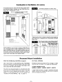
SPACE.*
*An unconfined space must have a volume of a minimum
50 cubic feet per 1000 Btuh of total of all appliances in
area. Adjoining rooms may be included only if there are
no doors between the rooms, or if special provisions are
made such as ventilation grilles installed between connecting rooms.
Fig 6, page 9 shows the minimum area in square feet, based on 8 foot ceiling heights, required for different Btuh
input ratings.
2. If you have a fireplace, open a window or door near
the fireplace and then check for spillage.
a. If spillage stops, do not use the fireplace without
a nearby window or door open until you can
supply fresh air by a permanent duct.
3. If you have kitchen and bathroom exhaust fans, turn
them off and check for spillage.
a. If spillage stops, do not use exhaust fans until
you can supply fresh air by a permanent duct.
Circuit breakers for fans should be turned off if
A. If your furnace is in an open area (unconfined space*)
the air that leaks through the cracks around doors and
windows may be enough for combustion and ventila-
possible.
m8--
Combustion
& Ventilation
WARNING,
Air (cont.)
provided with free air for proper combustion and ventilation of flue gases by one of the following methods.
DANGER OF PROPERTY DAMAGE,
BODILY INJURY OR DEATH
DRAFT HOOD SPILLAGE, WITH UNOBSTRUCTED
VENTS, INDICATES THAT ADDITIONAL AIR MUST
BE BROUGHT iNTO THE STRUCTURE FROM THE
OUTSIDE. KEEP A WINDOW OPEN (MINIMUM 2
INCHES) NEAR THE APPLIANCE UNTIL A PERMANENT AIR DUCT iS INSTALLED.
A. All Air From Inside Building:
If the confined space adjoins an unconfined space as
defined in EXAMPLE 1, provide two permanent openings,
one within 12 inches of the top and one within 12 inches
of the bottom of the room connecting directly to unconfined space. Each opening must have a free area of at least
100 square inches or 1 square inch per 1000 Btuh combined input of appliances in one room if combined input
exceeds 100,000 Btuh.
4. Spillage means air starvation and a fresh air duct
or air intakes must be installed to provide air directly
to the furnace or other gas appliance.
WARNING
DANGER OF PROPERTY DAMAGE,
BODILY INJURY OR DEATH
THE ADJOINING UNCONFINED SPACE MUST
HAVE ADEQUATE AIR INFILTRATION AS DEFINED
IN EXAMPLE 1.
D. If spillage exists or when the furnace is in a building
of tight construction where the windows and doors are
weatherstripped, air for combustion and ventilation
must be obtained from outdoors or space open to the
outdoors.
Provide an opening(s) having a total free area of 1 sq.
inch per 4000 Btuh of the total of all appliances. The
required area is shown in Fig. 9, page 10 under the
column for (40,000).
FOR EXAMPLE: Your furnace is rated at 50,000 Btu per
hour.The water heater is rated at 30,000 Btu per hour.The
total is 80,000 Btu per hour.You need two grilles, each with
100 square inches of free opening. Metal grilles have about
60% free area, so you need two metal grilles each with
160 square inches of Iouvered area.
FRESH AIR DUCT
HOLES FROM VENTILATED
ATTIC INTO STUD SPACE
SEE FIG 8
Refer to Fig. 7, page 10, which shows grille installation.
Using the previous example, the two connecting rooms
plus the closet must equal at least 500 sq. feet to handle
the combined input 50,000 plus 30,000.
MINIMUM
AREA IN SQUARE FEET
4000 Btuh Per
Square lnch
Opening
Round
Duct
AIR GRILLE
TO STUD SPACE
12" MAXFROM
HOLES
FROM
CRAWL SPACE
SEE FIG 8
HOLE IN BOTTOM OR
BACK OF FURNACE
INTO OPEN STUD SPACE
OR CRAWL
FLOOR
VENTILATED
INTO
STUD
Max. Btuh
Input
*Unconfined Space
Min. Area In Sq. Ft.
8' Ceiling Height
Rectangular
Duct
4" DIA.
3"x3"
SQ.
30,000
188
4" DIA.
3"x3"
SQ.
4" D[A.
3"x4"
SQ.
35,000
40,000
250
4" DIA,
3"x4"
SQ.
45,000
281
4" DIA.
3"x5"
SQ.
50_00
312
4_ '' DIA
3"x5"
SQ.
60_00
375
219
SPACE
*Can be two or more rooms joined
by ventilation
grilles.
B. All Air From Outdoors:
SPACE
If confined space doesn't adjoin an unconfined space
(defined in EXAMPLE 1) then air must be provided from
outdoors or spaces open to outdoors such as attic or crawl
spaces.
Fig. 5 shows a typical duct going into ventilated crawl
space or attic.
1. Duct must terminate at a point not more than 1 foot
above the floor.
Provide two permanent openings, one within 12 inches of
top, one within 12 inches of bottom of room connecting
directly, or by using ducts, with the outdoors or areas open
to outdoors.
2. Duct size must be at least 1 inch of free area for
each 4000 Btuh of input of all appliances in area.
EXAMPLE 2.
FURNACE LOCATED IN CONFINED
SPACE.
If furnace is installed in a confined
space, it must be
m9--
If opening connects directly to, or within vertical duets,
the free area of each opening must be at least 1 square
inch per 4000 Btuh combined input of appliances in area.
Combustion
& Ventilation
Air (cont.)
If horizontal ducts are used, the free area of each opening must be at least 1 square inch per 2000 Btuh combined input of appliances in area.
GRILLES
CONNECTING
UNCONFINED
ROOMS TO MAKE
SPACE
*Openings for inlet or outlet air should not be made into
attic area if attic is equipped with a thermostat controlled
power vent.
FREE AREA IN SQ. INCHES - EACHOPENING (FURNACE
ONLY) - BASED ON ONE SQ. INCH PER 4000 8TUH
FOR EXAMPLE: Your furnace is rated at 80,000 Btu per
hour. The water heater is rated at 30,000 Btu per hour. The
total is 80,000 Btu per hour. You need two grilles, each with
20 square inches of free opening, unless connected by
horizontal ducts which would require each grille or opening to have a free area of 40 square inches.
Recessed
Mount
Req'd Number of Holes
Sill or Header Plates
Furnace
Btuh / Input
of Opening
1_/2''
2"
3"
30,000
35,000
40,000
45,000
50,000
60,O00
7.5
8.75
10.0
11.25
12.5
15.0
7
8
9
10
11
13
4
5
5
6
6
8
2
2
3
3
3
4
Sq, Inch
Installation
FIND THE STUDS (See CAUTION on page 6)
CUT WALL OPENING
Use a stud Iocator or small finishing nails. Repeatedly
drive and remove a nail into the wall in the area of the
stud until it is located. Then find the inside edge of the
stud. Leave the nail at this location.
Provide an opening as shown in Fig. 10, page 11. Work
from the top in the attic to cut away the ceiling plate.
The other stud should be about 14-1/2 inches from the
one found. Drive finishing nails on the insides of this stud.
Draw wall cut out to required size as shown in Fig. 13,
page 12. If wall studs are not on 16 inch centers see
"CLOSE OFF STUD SPACE," Fig. 12, page 12.
--10--
ATTACH HEADER PLATE
MODELS: 5508331; 5508332; 6508731; 6508732
Locate header plate (Fig. 10, page 11) between wall studs
at 88V2 inches from finished floor and nail into position
with end flanges pointing up.
Recessed
Mount
A hole must be drilled for the gas line supply.
5008731; 5008732
Locate header plate between wall studs at 821/2 inches
from finished floor and nail into position with end flanges
pointing up.
MODELS:
(cont.)
GAS SUPPLY OPENING
See Fig. 10.
MODELS:
Installation
3508331; 3508332; 3508731; 3508732
Locate header plate between wall studs at 74 inches from
finished floor and nail into position with end flanges pointing up,
Decide whether the gas line will come through the floor
or wall stud.
NOTE
If a pre-existing gas piping stub location is not compatible with hole or knock-out provided in furnace, you may
make an alternate entry hole in furnace back wall per Fig.
13, page 12.
CAUTION
ALL MODELS
Hole for electrical conduit is located on left side of header
plate as you face the wall.
WARNING
REMOVE 4x14 FIBERGLASS GASKET FROM BOTTOM OF HEADER PLATE AND DISCARD. THIS
GASKET IS NOT USED WHEN THE FURNACE IS
RECESSED IN THE WALL.
Be careful not to damage any furnace components
while making any alternate hole.
Locate and drill one (1) 1-1/2 inch hole at selected locations per Fig. 11 and Fig. 13, page 12 or Fig. 14, page !3.
Gas line can be run at this time or done after furnace
is mounted, see section GAS SUPPLY AND PIPING,
page 17.
B/W VENT PIPE
(NOT SUPPLIED)
7_r HOLD-DOWN OR
STARTER PLATE
/
F-
_(NOT
N01_:
WALL BOARD &
FLOOR PLAI_
SUPPLIED)
REMOVED
FOR
RECIE_
MOUNT
ONLY
_LEXIBLE
ELECTRIC,
2"
N
ONDUIT
CONVENI ENCE-_
HEADER
PLATE
OUTLET
,'- FINISH
FLOOR
SURFACE _
MOUNTING
MOUNTING
/
CLOSE OFF STUD SPACE (If Required)
If studs are not on 16 inch centers, cut the hole for the
furnace next to an existing stud and frame in the other side
using a 2 x 4 and spacer blocks as required. See Fig. 12,
page 12.
/
f
--
.
j
ELECTRICAL SUPPLY ROUGH-IN
Run the electrical supply with the ground wire and thermostat cable into stud space above furnace location.
--11 m
Recessed
Mount
Installation
(cont.)
CAUTION
CLOSE OFF STUD SPACE (If Required)
Do not run wire behind flanges of header plate or
in any location where it might be damaged. Avoid
splicing thermostat wire unless the spliced wires are
properly cleaned, soldered and taped.
7
PLA'I_
F
I_]b-I1NG
b-lUD
II
NEW S'IUD
Ill
.,_,-
FRONT
TOP
111
[41C
III
E_S71NG S31JD t
]
%
ELEC
_,/"
CONN.
",+--141/6"-_-
SPACER
I -- 14-_/8"_-
1
.....
LI-1
III
H I
r-!U-I......
If desired, the power supply and thermostat cable can
come into the wall stud space from a basement, crawl
space or an adjoining stud space.
Terminate flexible electrical conduit at the junction box
located on the underside of the header plate. Leave the
wires long enough to connect inside the junction box to
the convenience outlet.
BOTTOM
(1) MODELS:
5508331;
5508332;
6508731 ; 6508732
Surface
Mount
FIND THE STUDS AND CEILING JOISTS
(See CAUTION on page 6)
(2) MODELS:
5005731;
5008732
(3) MODELS:
3508331;
3508332;
3508731;
3508732
Installation
CUT CEILING OPENING
Find two studs at spot where furnace is to be placed.
Use a stud indicator or small finishing nails. Repeatedly
drive and remove a nail into the wall in the area of the
stud until you find it. Then find one side. Leave the nail
there. Drive another nail just on the other side of the same
stud.
Mark off and cut 3-1/2 x 12 inch rectangular hole in ceiling, centered between wall studs. The back edge of the
opening should be about 1/8 inch from the wall. See Fig.
16, page 14.
ELECTRICAL
SUPPLY ROUGH-IN
Inside edge of the other stud should be about 14-1/2
inches from the one found. Drive finishing nail on inside
edge of this stud.
The electrical supply openings must be made in the wall
or ceiling above furnace to match holes in furnace top.
Holes in furnace top are 1 inch from the left side of furnace. See Fig. 13.
Using the nails as a guide, draw a line up both sides to
the ceiling to locate hole cut out for vent pipe and electrical connections.
If desired, the power supply and thermostat cable can
come into the wall stud space from a basement, crawl
space or an adjoining stud space.
--12--
Surface
Mount
Installation
(cont.)
CAUTION
At selected location, drill a 1 inch hole for 115V power
supply and a 1/2 inch hole for the thermostat cable.
I
Run wiring through holes to above furnace top leaving
enough excess wire to make electrical connections after
mounting furnace.
while
making
alternateany
hole.
e careful
not any
to damage
furnace components
Locate and drill one (1) 1-1/2 inch hole at selected location per Fig. 11, page 11; Fig. 13, page 12; or Fig. 14.
Gas line can be run at this time or done after the furnace
is mounted, see section CONNECTING GAS LINE.
CAUTION
To avoid damage to wiring, be sure to route wire away
from path of furnace vent.
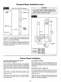
ALTERNATE GAS SUPPLY OPENING
GAS SUPPLY OPENING
r;
A hole may need to be drilled for the gas line supply.
Decide whether the gas line will come through the floor
or wall.
NOTE
If you decide to route gas line through right side of furnace, simply remove the knock-out provided in furnace
side.
ALTERNATE GAS SUPPLy---"%._I
ENTRy LOCA]10N
NOTE
?
If a pre-existing gas piping stub location is not compatible with hole or knock-out provided in furnace, you may
make an alternate entry hole in furnace back wall per
Fig. 14.
General
Vent
)--'t
GAS SUPPL_
ENTRy HOLES
Installation
The vent installation must comply with all local codes and
ordinances. If in doubt, consult your local codes or
inspector.
serves, the vent system may be completed with a type B
gas vent, of the same manufacturer, and offsets or
breakovers shall not be greater than 45 degrees from
vertical.
The furnace vent must be directed to the outdoors so that
harmful combustion gases will not collect inside the
building.
NOTE
This furnace must not be connected to a chimney flue
serving a separate solid-fuel burning appliance.
Use U.L. listed B/W Vent Kit 9901. You must provide other
items, not contained in kit, necessary to complete your
specific venting situation through the roof. Refer to typical
venting system shown in Fig. 18, page 15.
Type B/W gas vent shall extend from the header plate of
the vented wall furnace to a point above the highest ceiling plate within a stud space through which the vent
passes, without any offsets or crossovers thei'ein. After a
type B/W gas vent passes through the highest ceiling
plate within a stud space above the furnace which it
--13--
The B/W vent must extend through the ceiling and roof
terminating at least 12 feet above the finished floor on
which the furnace rests.
First vent pipe offset (if required) is recommended
be any closer than 2'-0" from header plate.
ATTACH HEADER & HOLD-DOWN
(SURFACE MOUNT)
not to
PLATE
Remove the fiberglass
flue collar from the furnace flue
extension. This gasket is not used when the furnace is surface mounted.
Make sure that the 4 x 4 inch gasket is in position on the
header plate.
General
Vent Installation
(cont.)
Discard the three (3) square gaskets, as they are not used
when furnace is surface mounted.
INSTALL CEILING PLATE SPACERS
(SURFACE MOUNT)
Slide header plate over the furnace flue extension with the
junction box entering the opening in top of furnace.
Refer to Fig. 16.
Only one (1) plate spacer is required for surface mounting within a single story dwelling.
Refer to Fig. 15.
Fasten to matching holes in the furnace top through holes
"A" in the header plate, using two (2) #8 x 3/8 inch screws
provided.
Fasten the hold-down plate or starter plate to the top of
the header plate using holes "B" in the header plate.
j
Cut 2 inches off each end of plate spacer.
Drill two (2) 3/16 inch holes in each end of plate spacer.
See Fig. 18, page 15.
Fasten plate spacer to wall by nailing through one (1)
drilled hole in each end, into the wall board and ceiling
plate.
INSTALL CEILING PLATE SPACER
(RECESSED MOUNT)
,,g,,
Refer to Fig. 17.
Two ceiling plate spacers are in the B/W vent kit. They
must be fastened along each long edge of the ceiling hole
to hold the oval vent pipe in the center of the hole.
ALL MODELS
ATTACH HOLD-DOWN
PLATE (RECESSED
Nail the ceiling plate spacers either across or in between
the cut out section of ceiling plate. If nailed between, ends
must be bent at 90 degrees.
MOUNT)
NOTE
CEILING
Header plate should already be attached to wall studs. See
ATTACH HEADER PLATE, page 10 and 11.
PLATE SPACERS - RECESSED
_
MOUNT
14 318
Fasten hold-down plate to top of header plate using two
(2) screws provided.
CEILING PLATE
"_"
r,_4_3V2 CENTERED
!1 a/w VENT
TOP
___
ON
HOLE IN
INSTALL
SURFACE
VENT
(SURFACE
MOUNT)
NOTE
For surface mounting, it will be helpful to complete the gas
piping supply to the furnace before installing the vent pipe.
See section GAS SUPPLY & PiPiNG, page 17.
HOLD-DOWN
OR
RTER PLATE
r_
(NOT
SUPPLIED)
HEADER
PLATE
Carefully move the furnace into position under the ceiling
cutout.
FRONT
SIDE
Insert first lengths of oval, double wall vent pipe up through
the ceiling cutout.
--14 m
General
Vent Installation
(cont.)
Lower vent pipe to the hold-down plate. Push the vent
pipe into the hold-down plate until it is completely
seated. (Hold-down cleats will engage the groove in the
vent pipe.)
TYPICAL VENT INSTALLATION
1
Vl_IT CAP "rOBE AMINo OF2 FT. HIGHER
THAN ANY pOINT _
10 FT. OF _rr
C_
Secure hold-down plate to vent pipe using two (2) screws.
Using plumbers tape to secure vent to the plate spacer,
nail through one (1) hole in each end of plate spacer, into
the wall and ceiling plate.
INSTALL FURNACE VENT (RECESSED MOUNT)
Lower first lengths of oval, double wall vent pipe through
the plate spacers to the hold-down plate.
Push the vent pipe into the hold-down plate until it is completely seated. (Hold-down cleat will engage the groove
in the vent pipe.)
Secure hold-down plate to vent pipe using two (2) screws.
COMPLETE THE VENTING
2 E_DS
Refer to Fig. 18.
HEADER PLA1E
Install oval to round adapter. Complete the piping extending it through the roof. Use 4" round, double wall (Type
B) vent pipe, roof flashing, storm collar, and vent top as
shown. The vent cap must be at least 2 feet higher than
any point that is within 10 feet horizontally of the vent cap.
There must be at least 1 inch clearance between the vent
pipe and any combustible material.
FLUE
COLLAR
QAS_£T
IMPORTANT
Area above header within the stud space MUST be kept
clear of any attic insulation to allow the free circulation of
air around oval vent piping.
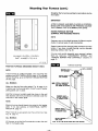
Mounting
Your Furnace
To obtain adequate clearance for fastening furnace or to
install gas supply fittings, it may be necessary to remove
the burner and control assembly as follows:
Remove burner compartment
and up.
door by pulling door top out
Locate the air discharge shield. It is secured across the
top of the burner control compartment. Remove two (2)
screws and shield and set aside.
DISCONNECT WIRING
MODELS 3508331; 3508332; 5508331; 5508332
Remove the screws holding the ignition control unit and
cover to the furnace casing.
Disconnect wires to free control module from its mounting location. Mark or tag each wire removed for its exact
reconnection. See Fig, 19, page 16,
--15--
ALL OTHER MODELS
Disconnect two (2) 24 volt wires from the gas valve.
Disconnect two (2) wire connectors from junction block
midway on the thermocouple.
REMOVE BURNER AND CONTROLS
MODELS: 3508331; 3508332; 3508731; 3508732
Locate the burner and screws that secure it. Remove the
two (2) screws (one from each end). Lift one end of the
burner at a time until free. Remove burner and controls
from the compartment.
ALL OTHER MODELS
Locate
the two
hinges.
burner
the burner and hex nuts that secure it. Remove
(2) hex nuts (one from each end). Flip up the wire
Lift one end of burner at a time until free. Remove
and controls from the compartment.
Mounting
Your Furnace
(cont.)
Straighten the furnace by pushing furnace bottom intothe
stud space.
IMPORTANT
AFTER FURNACE HAS BEEN PLACED IN POSITION,
MAKE SURE THE GASKETS ARE PRESSING AGAINST
THE FURNACE TOP TO ELIMINATE AIR LEAKS.
FASTEN FURNACE BOTTOM
(SURFACE AND RECESSED MOUNT)
24V
PV
SEt6
24V
GND
NOTE
Fasteners are not furnished because of different requirements of various types of wall construction.
lnV
Fasten furnace to floor through holes provided in furnace
bottom. If you have concrete flooring, use an alternate
fastening method. See Fig. 20.
GND
WILLIAMS
IGNITION
PART NUMBER
If burner and control assembly were removed, replace
them by reversing "DISCONNECT
WIRING"
and
"REMOVE BURNER AND CONTROLS"
sections on
page 15.
CONTROL
P321910
LA707-01
.DWG
FURNACE
MOUNTING
POSITION FURNACE (RECESSED MOUNT ONLY)
- METAL ANOH(_
NOTE
TOP FASTENING
If your furnace is surface mounted, your mounting was
started during VENT INSTALLATION, page 13.To complete
furnace mounting, go on to FASTEN FURNACE BOTTOM
on this page.
II
I
I
ALL MODELS
Make sure that the flue collar gasket, Fig. 18, page 15, is
in place over the flue extension. Check to see if header
plate gaskets are in place.
Hold the furnace at a slight angle (top closer to the wall
than bottom) with the flue extension centered under the
oval hole in the header plate.
NOTE
Electrical wiring should already be routed to the header
plate. If not, see sections on ELECTRICAL SUPPLY
ROUGH-IN, page 12.
Place three (3) square gaskets over the junction box. See
Fig. 18, page 15.
ALL MODELS
Lift furnace up so that the flue extension enters the oval
hole in the header plate.
--16--
NOTE: DO NOT U_
BOTTOM DOOR _
FOR MOUNTING
Mounting
Your Furnace
IMPORTANT
TO PREVENT DAMAGE TO WIRING, MAKE SURE
NOT TO PINCH THE WIRES BETWEEN FURNACE
COMPONENTS. KEEP THEM ROUTED AWAY FROM
THE BURNER.
Resecure the air discharge shield across the top of the
burner and controls compartment, Small leg of "L" shape
must be positioned toward floor, pointing away from front
of furnace.
(cont.)
over the back flange of furnace top and screwing to wall.
See Fig. 20, page 16.
FASTEN FURNACE TOP (RECESSED MOUNTING)
Fasten furnace top by drilling two (2) holes through the
side flanges of furnace top and securing with two (2)
screws or nails into the wall studs. See Fig. 20, page 16.
CAUTION
FASTEN FURNACE TOP (SURFACE MOUNTING)
Fasten furnace top to wall using two (2) metal anchors
(packed in plastic bag with thermostat) by placing them
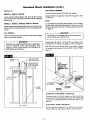
Gas Supply
Gas control valve, within the furnace, is shipped with a
seal over gas inlet tapping. Do not remove seal until ready
to connect piping.
WARNING
Be careful not to damage furnace components or wiring when drilling holes,
and Piping
GAS PIPING
The gas supply line must be of adequate size to handle
the BTU/HR requirements and length of the run for the
unit being installed.
Determine the minimum pipe size from Fig. 23, page 18,
basing the length of the run from the gas meter or source
to the unit.
DANGER OF PROPERTY DAMAGE,
BODILY INJURY OR DEATH.
MAKE SURE THE FURNACE IS EQUIPPED TO
OPERATE ON THE TYPE OF GAS AVAILABLE.
MODELS DESIGNATED AS NATURAL GAS ARE TO
BE USED WITH NATURAL GAS ONLY, FURNACE
DESIGNATED
FOR USE WITH LIQUIFIED
PETROLEUM (L.P) GAS HAVE ORIFICES SIZED
FOR COMMERCIALLY
PURE PROPANE GAS,
THEY CAN NOT BE USED WITH BUTANE OR A
MIXTURE OF BUTANE AND PROPANE.
DROP
I
PIPED
i_ I
SUPPLy
GAS
CR0UN0 JOINT
aN,0N
GAS SUPPLY
For Natural gas, the minimum inlet gas supply pressure
for the purpose of input adjustment is 5" water column.
The Maximum inlet gas supply pressure is T' water
column.
For L.E gas, the minimum inlet gas supply pressure for
the purpose of input adjustment is 11" water column. The
maximum inlet gas supply pressure is 13" water column.
Gas pressure and input to the burners must not exceed
the rated input and pressure shown on the rating plate. On
Naturel Gas the manifold pressure should be 4 inches
water column. The manifold pressure should be 10.5 inches water column for L.P. Gas. See page 32 for operation
above 2000 feet altitude Office change may be required to
suit gas supplied. Check with your local gas supplier.
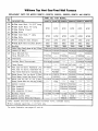
ORIFICE SIZES
Furnace Technical Information, page 32, shows the
correct orifice sizes for the different input ratings when
using Natural or L.P Gas.
--17--
tlANUAL
SHUT
VALVE
DF(Op
OFF
Gas Supply
and Piping (cont.)
CHECKING THE GAS PIPING
PROPER
2 IMPERFECT
THREADS
THREAD
PIPE
PIPING
CONTRO
Test all piping for leaks. When checking gas piping to the
furnace with gas pressure less than 1/2 PSI, shut off
manual gas valve for the furnace. If gas piping is to be
checked with the pressure at or above 1/2 PSI, the furnace and manual shut off valve must be disconnected during testing. (SEE WARNING BELOW.) Apply soapsuds (or
a liquid detergent) to each joint. Bubbles forming indicates
a leak. Correct even the slightest leak at once.
PRACTICE
L
USE
MODERATE
AMOUNT
OF
DOPE
_
RIGHT
LENGTH
LEAVE
2 END
THREADS
[IARE
"
All piping must comply with local codes and ordinances
or with the National Fuel Gas Code (ANSI Z223.1),
whichever applies. In Canada: Follow CAN 1-B149 Installation Code.
Refer to Fig. 21, page 17,for the general layout at the unit.
It shows the basic fittings needed.
The following rules apply:
1. Use new, properly reamed pipe free from chips such
as steel or black iron pipe and fittings or other
approved by local codes.
2. Do not thread pipe too far. Valve distortion or malfunction may result from excess pipe within control.
Apply moderate amount of good quality dope to pipe
only, leaving 2 end threads bare. If LP Gas installation,
use compound resistant to action of liquified petroleum
gases.
3. Use ground joint unions.
4. Install a drip leg to trap dirt and moisture before it can
enter the gas valve. Drip leg must be a minimum of 3
inches long.
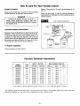
GAS PIPE SIZES
NATURAL GAS
PIPE CAPACITY - BTU PER HOUR
(INCLUDES FITTINGS)
PIPE SIZE
LENGTH OF
PIPE - FEET
1/2 inch
3/4 inch
20
40
60
92,000
63,000
50,000
190,000
130,000
105,000
1 inch
350,000
245,000
195,000
L.P. GAS
PIPE CAPACITY - BTU PER HOUR
(INCLUDES FITTINGS)
LENGTH OF
PIPE - FEET
1/2 inch
3/4 inch
1 inch
20
40
60
189,000
129,000
103,000
393,000
267,000
217,000
732,000
504,000
409,000
WARNING
5. Install a manual shut-off valve.
6. Provide a 1/8 NPT test gauge connection immediately
before the gas supply connection to the furnace.
GAS CONNECTION
If installation is for L.R Gas, have L.R installer use twostage regulation and make all connections from storage
tank to furnace.
Use two pipe wrenches when making the connection to
the valve to prevent turning or damage to gas valve.
Connection between manual shutoff valve and burner control assembly can be made with an A.G.A./C.G.A. design
certified flexible connector if allowed by local codes. Drip
leg and ground joint union are still required.
Tighten all joints securely.
Electrical
All electrical work must conform to your local codes and
ordinances or in their absence, with National Electrical
Code, ANSI/NFPA 70. If you are not familiar with wiring
codes, in general, have a competent electrician do this
job. In Canada: Follow C22.1, Canadian Electrical Code.
m18m
DANGER OF PROPERTY DAMAGE,
BODILY INJURY OR DEATH.
NEVER USE A MATCH OR OPEN FLAME TO TEST
FOR LEAKS. NEVER
EXCEED SPECIFIED
PRESSURES FOR TESTING. HIGH PRESSURES
MAY DAMAGE THE GAS VALVE AND CAUSE
OVER-FIRING WHICH MAY RESULT IN HEAT
EXCHANGER FAILURE. LIQUID PETROLEUM
(L.P.) IS HEAVIER THAN AIR AND IT WILL SETTLE
IN ANY LOW AREA, INCLUDING OPEN DEPRESSIONS AND IT WILL REMAIN THERE UNLESS
AREA IS VENTILATED.
NEVER ATTEMPT STARTUP OF UNIT BEFORE
THOROUGHLY VENTILATING AREA.
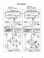
Wiring
ELECTRICAL CONNECTION
REMOVE FAN SHROUD
Take out four screws holding fan shroud to side flanges
of cabinet and remove shroud. See Fig. 1, page 5.
WARNING
LOW VOLTAGE CONNECTIONS
DANGER OF PROPERTY DAMAGE,
BODILY INJURY OR DEATH.
TURN OFF ELECTRIC POWER AT FUSE BOX
OR SERVICE PANEL BEFORE MAKING ANY
ELECTRICAL CONNECTIONS.
INSULATE WHERE NECESSARY.
ALL LINE VOLTAGE AND GROUND CONNECTIONS
MUST
BE COMPLETED
BEFORE
ELECTRICAL POWER IS RESTORED.
ELECTRICAL
CAUTION
The Heat Anticipator WILL BURN OUT if 24 volts are
applied directly to thermostat by shorting out the gas
valve or primary control during testing or by incorrect
wiring.
WALL THERMOSTAT WIRING
Run thermostat wire to the furnace.
POWER SUPPLY
Avoid splicing thermostat wire unless the spliced wires are
properly cleaned, soldered and taped.
A branch circuit including this furnace must not exceed
15 Amperes, or run a separate 115V, 60 Hz, 15 Ampere
circuit from a separate circuit breaker or fuse in your service entrance panel to the furnace junction box. Do not
run supply wires inside the furnace cabinet, except from
the top of cabinet down to junction box.
Connect thermostat to two wires marked "Thermostat"
extending from top of furnace, using two wire nuts provided. See Wiring Diagrams, pages 37 or 38.
CAUTION
JUNCTION
BOX
Do not connect 115V service line to the gas control
valve or the wall thermostat.
CAUTION
]
1
Be careful not to damage the fan blade when making the 115V connection to the convenience outlet.
I
115V supply wiring connection is made within the upper
left corner of the furnace cabinet.
Locate 115V plug and push into the convenience outlet
attached to the bottom of header plate. (It protrudes
through the rectangular opening in the furnace top.)
ALL MODELS
Reinstall fan shroud to furnace front. Slots in fan shroud
allow up/down adjustment. Make sure the fan blade spins
freely. Tighten screws securely.
Replace top front panel and secure with thumbscrew.
Refer to paragraph covering GAS AND ELECTRICAL
SUPPLY OPENINGS, page 13. Follow Wiring Diagrams,
pages 37 or 38.
If you have any doubt regarding electrical hookup, or compliance with code or ordinance, consult your electrical inspector or a licensed electrician.
GROUNDING
A ground lug is installed for the ground connection. Use
a copper conductor (#14 AWG) from the unit to a grounded connection in the electric service panel or a properly
driven and electrically grounded ground rod.
I19--
COMPLETE
WIRING
DIAGRAMS
ON PAGES 37 AND 38.
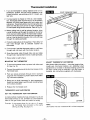
Thermostat
Installation
1. If an old thermostat is being replaced and is in a
satisfactory location and the wiring appears to be
in good condition, use existing wiring. If in doubt, use
new wire.
ROUTE THERMOSTAT CABLE
2. If a new location is chosen or if this is a new installation, thermostat cable must first be run to the location
selected. All wiring must agree with local codes and
ordinances. These instructions cover bringing the wire
down from the attic but it can be run from a basement
or crawl space using similar methods. Refer to Fig. 24.
3. Before drilling hole in wall at selected location, drive
a small finishing nail through the ceiling in the corner
of the wall and ceiling above the thermostat location.
Pull the nail out and push a small stiff wire through the
hole so it can be found in the attic. Drill a 1/2 inch hole
through the ceiling wall plate.
Ske,
AL t
FINISH
NAIL
TO
LOCATE
HEADER
4. Probe for obstructions in the partition. Then drill a 1/2
inch hole through wall at selected location for
thermostat.
THERMOSIAT
CABLE
5. From the attic, feed the thermostat cable or a stiff wire
through wall until even with thermostat location.
6. Snag thermostat cable through hole and pull cable
through hole in wall so that 6 inches of cable protrudes.
STIFF WIRE
TO SNAG
CABLE
7. Route cable to wall furnace.
MOUNTING
THE THERMOSTAT
ADJUST THERMOSTAT
1. To remove thermostat cover, squeeze both sides and
lift. See Fig. 25.
2. 'Connect thermostat wires to the terminal screws on the
thermostat base.
ANTICIPATOR
Many factors affect this setting -- room size, length of thermostat wire, thermostat location, etc. Additional small
adjustments to increase or decrease heating cycles (4-6
per hour typical) may be required. If an amp meter is
available, see instructions supplied with thermostat.
3. Push any excess wire back through hole in wall and
plug hole with insulation to prevent drafts from affecting thermostat operation.
4. Being sure to level thermostat for best appearance,
fasten thermostat base to wall through mounting holes
with screws provided.
5. Replace the thermostat cover.
THERMOSTAT HEAT ANTICIPATOR
SET THE
THERMOSTAT
SQUEEZE RR_4LY
SOl1"1SIDES
AND UFT 110
R£_IO_,_ COVER
HEAT ANTICIPATOR
A simple method of setting the heat anticipator in a 24-volt
thermostat (without an A.C. ammeter) is to first read the
label on the gas control valve and match its rating.
Example:
If the ampere draw for the valve is .5 amps,
set thermostat
heat anticipator
at the same
setting (.5). (Fig. 26, page 21.)
t,/_r/...oa.l=t_
NOTE
Use heavier wire size if more than 20 ft. of wire is required.
--20--
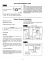
Thermostat
Installation
(ton't)
NOTE
Refer to installation instructions packed in the thermostat
carton if you have any doubt about the above procedures.
MV "--X.-_J_
.---,.- 1.0 .-'--
HEAT
AN 0,P TOR
'_
SETTING
-LONGER
CYCLE
When all is adjusted properly, the furnace burner should
shut off slightly before the desired room temperature is
reached. The stored heat in the appliance is enough to
bring room temperature up to desired level. The heat
anticipator thus makes it possible to maintain very close
temperature control.
u_.-_,._m
For longer "ON" time, move anticipator clockwise.
For shorter "ON" time, move anticipator counterclockwise.
Optional
SIDE OUTLET
Accessory
NO. 6701
Installation
CUT WALL OPENING(S)
REAR OUTLET NO. 6801
Make an opening(s) in the wall(s) for a Side and/or a Rear
Outlet Register. See Fig. 27.
SHORT REAR OUTLET NO. 6802
CUT WALL OPENING
SIDE OUTLET
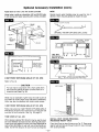
CAUTION
Use only Boots and Grilles
manufacturer.
provided
REAR OUTLET
II
by the
°IIs'_os/ II
CLEARANCES
IMPORTANT
Carefully follow all measurements
to ensure proper installation.
. II
FURNACE "BACK"
AGAINST WALL _
Ill
a-1/4" L_
and clearances given
ll-s/8"
.-s/s'! I
l
When SiDE OUTLET 6701 is used, the furnace casing
must be exactly 4 inches from an adjacent side wall
(except may be 3/4" minimum when 1-WAY FRONT
DIFFUSING GRILLE is used). See Figs. 28 and 29,
page 22.
II
II
F1NI_tlE9FLOOR,-J_
11
RNISHED FL_
When REAR OUTLET 6801 or SHORT REAR OUTLET
6802 are used, the furnace casing must be a minimum
of 12 inches from an adjacent side wall. See Figs. 3D and
3F, page 7.
CUT CASING OPENING(S)
Before setting the furnace into position, cut a 5 x 7 inch
rectangular opening for Side Register, or 7 x 11 inch opening for a Rear Outlet Register where marked on the furnace casing. Cut carefully as edges must be straight and
smooth. See Fig. 13, page 12.
--21--
/1/1
3/4" MIN
WHEN
6704 ONE-WAY
FRONT
GRILLE
DIFFUSING
IS USED
OPTIONAl,
I IR,-v,-
m '"
"J_
-
3/4"
Optional
Accessory
Installation
(cont.)
INSTALL PLASTERGROUNDS
Install Plastergrounds as shown in Figs. 29 and 30.
Flanges of Plastergrounds extend the normal thickness
of plaster. If "DRYWALL" or other thin material, flanges
must be trimmed off flush with wall surface.
REAR PLASTER GROUND CENTERS
ON THE BACK OF THE HEATER
- PLASTER GROUND
EXACTLY
t
1/4 ROUND
TRiM
METAL
FILLER
Press Inner Boot against furnace Inner Liner, mark and
cut off flush with the wall surface.
Fasten Outer Boot securely to furnace casing with screws
provided.
EXACTLY
41/2 FROM
BACK
OF THE
SIDE OUTLET ONLY
HEATER
Position inner Boot against furnace Inner Liner and fasten
securely through all holes with screws provided.
"
REAR
GROUND
._
._
OUTLET
ONLY
Ptace Inner Boot in position and fasten with screws along
the top and bottom edges only. Place Damper Assembly
inside Inner Boot and fasten with one (1) screw on each
side. Thread chain through key hole in clip on Outer Grille
and attach the Bell end.
PLASTER
15_/4"
SIDE AND REAR OUTLETS
FLOOR
Place Outlet Grille into position, drill through the wall
material and Plasterground with a #33 drill bit, using
the holes in grille as a template and secure with screws
provided.
MOUNTING
Refer to Fig. 31.
BEFORE placing the furnace into position, place Out Boot
against the furnace casing with inside of flanges exactly
on edges of hole in casing. Mark hole locations on casing through the holes in Out Boot flanges
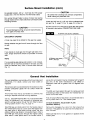
VENT ENCLOSURE KIT INSTALLATION
(SURFACE MOUNT ONLY)
Refer to Fig. 32, page 23.
Drill #33 holes in casing at marked locations.
Cut Side Panels to fit between the top of furnace casing
and ceiling.
Remove knockout plate and knockouts for screws from
Inner Liner.
Fasten Side Panels to wall parallel to furnace casing sides.
SIDE REGISTER ONLY
Cut Front Panel height to fit. Note that the bottom edge of
Front Panel is notched to fit into the furnace casing recess.
Secure a 1 x 1 wood strip (not included in this kit) to wall
surface next to side outlet as a backup for metal filler strips.
Fasten metal filler strips to side of furnace casing with front
surface exactly opposite front of wood backup strip.
SIDE AND REAR OUTLET REGISTERS
Place furnace in position.
With furnace in position, pass Outer Boot through Plastergrounds, holding it firmly against furnace casing. Mark and
cut off the end of the Outer Boot flush with the wall surface.
--22--
Fasten Front Panel to Side Panels with screws provided.
SIDE CASING GRILLE KIT NO. 6702
See clearances Fig. 33, page 23.
Locate marked opening(s) on furnace casing. Mark
and cut an opening 1 inch wider than opening already
marked (1/2 inch larger on all four sides). See Fig. 13,
page 12.
Remove knockout plate and knockouts for screws from furnace inner liner.
Optional
Accessory
Installation
(cont.)
Fasten Boot to Inner Liner with screws provided.
NOTE
Using holes in grille as a template, drill two (2) #33 holes
in out casing and fasten securely with screws provided,
Quarter-round wood molding may be used for trim if
desired, which may be painted to match the wall.
LOWER
DOOR
CASING
CEILING
JOIST
B/W
VENT
OPTIONAL TWO-WAY DIFFUSING
GRILLE 6703
:VENT
ENCLOSURE
C
VENT
ENCLOSURE
FRONT
!ILING
_OPTIONAL
REAR
DISCHARGE
i
o
'll
\\k-,2
T W O -WAY
OIFFU SING--_
GRILLE
KIT 6703
OPTIONA _L_I
h_OPTIONAL
OUTLET _
II_ 0UTLET
KIT 6702
_'"
_I
--4
KIT 6702
o(Nill
KIT 470R_
OPTIONAL
TRIM
ST
WALL
WITH
FASTENERS
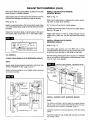
2-WAY FRONT DIFFUSING GRILLE KIT NO. 6703
PROVIDED
Refer to Fig. 34.
CAUTION
For use only in conjunction with a front outlet when
the furnace is spaced at least 12 inches from an intersection wall (see Fig. 35).
]
Metal clips on backside of grille snap into side louvers of
front warm air outlet. Adjust clips with pliers if necessary.
Grille may also be attached with sheet metal screws.
VENT
COVER
j
,==..
TRIM
MOULDING
(OPTIONAL}
1-WAY FRONT DIFFUSING GRILLE KIT NO. 6704
Follow instructions for 2-WAY FRONT DIFFUSING GRILLE
6703 above, except furnace clearance to an adjacent wall
must be 3/4 inch minimum. See Fig. 28, page 21.
TRIM
STRIP
KIT NO. 4701
When desired, optional Trim Strip Kit may be used to cover
the crack between furnace and wall. See Figs. 36 and 37.
Place strips tight against furnace with other edge against
wall surface and fasten to wall with escutcheon pins provided. Cut off trim strips to fit each furnace as required.
--23--
INSTALL VENT COVER (PROVIDED)
(RECESSED MOUNT ONLY)
Place Vent Cover on top of furnace, see Fig. 37. Press snug
against wall and secure through bottom to top of furnace
with screw provided.
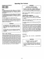
Start-Up
Procedure
Start the furnace using the procedures in section
OPERATING YOUR FURNACE.
WARNING
DANGER OF BODILY INJURY OR DEATH.
LIQUIFIED PETROLEUM L.P. GAS IS HEAVIER
THAN AIR AND IT WILL SETTLE IN ANY LOW
AREA, INCLUDING OPEN DEPRESSIONS AND
IT WILL REMAIN THERE UNLESS AREA IS
VENTILATED.
NEVER ATTEMPT START-UP OF UNIT BEFORE
THOROUGHLY VENTILATING AREA.
manometer having a scale range from 0 to 12 inches of
water should be used for this measurement. The manifold
pressure must be measured with the burner and pilot
operating. Any major changes in flow must be made by
changing the size of the burner orifice. Check with your
local gas supplier for proper orifice sizing.
CHECK THE GAS INPUT (NATURAL GAS ONLY)
To measure the input using the gas meter, proceed as
follows:
1. Turn off gas supply to all other appliances except the
furnace.
Check the furnace operation as outlined in the following
instructions. If any sparking, odors or unusual noises are
encountered, shut off electric power immediately. Recheck
for wiring errors, or obstructions in or near fan motor.
2,
WARNING
With the furnace operating, time the smallest dial on
the meter for one complete revolution. If this is a 2 cubic
foot dial, divide the seconds by 2; if it is a 1 cubic foot
dial, use the time in seconds as is. This gives the
seconds per cubic foot of gas being delivered to the
furnace.
NATURAL GAS HEATING VALUE (BTU PER CUBIC
FOOT) CAN VARY SIGNIFICANTLY, THEREFORE,
IT IS THE INSTALLER'S RESPONSIBILITY TO SEE
THAT BTU INPUT TO THE FURNACE IS ADJUSTED
PROPERLY. FAILURE TO DO SO COULD CAUSE
HEAT EXCHANGER FAILURE, ASPHYXIATION, FIRE
OR EXPLOSION, RESULTING iN DAMAGE, BODILY
INJURY OR DEATH. REFER TO THE NATIONAL
FUEL GAS CODE (NFPA-54) TO BE SURE THE FURNACE IS BURNING FUEL AT THE PROPER RATE.
3. Assuming natural gas with a heating value of 1000 Btu
per cubic foot and 34 seconds per cubic foot used as
determined by step (2), then:
Underfiring could cause inadequate heat, excessive condensation or ignition problems. Overfiring could cause sooting flame impingement or overheating of heat exchanger.
Before starting natural gas input check, obtain heating
value of gas (BTU per cubic foot) at standard conditions
from your local supplier. This factor is used in "Check the
Gas Input" section and procedure.
ADJUST PILOT BURNER
(STANDING PILOT MODELS ONLY)
Pilotflame should surround 3/8 inch to 1/2 inch of the thermocouple tip. To adjust, remove pilot adjustment screw on
gas valve. Turn screw counterclockwise to increase flame,
clockwise to decrease. Replace cap.
Second per hour = 3,600
Input = 1,000 x 3,600 + 34 =106,000 BTU Per Hour
This measured input must not be greater than the input indicated on the rating plate of the furnace.
4. Relight all other appliances turned off in step 1 above.
Be sure all pilot burners are operating.
CHECK THERMOSTAT
CHECK GAS INPUT AND PRESSURES
For furnace located at elevations between sea level and
2000 feet, the measured input must not be greater than
the input shown on the rating plate of the furnace. For
elevations above 2000 feet, the measured input must not
exceed the input of the rating plate reduced by 4 percent
for each 1000 feet that the furnace is above sea level.
Check thermostat operation. When set above temperature
shown on the thermostat, the main burner should light.
Make certain the thermostat turns off the furnace when
room temperature reaches the selected setting and starts
the furnace when room temperature falls a few degrees.
MAKE SURE THERMOSTAT ANTICIPATOR IS SET
PROPERLY, SEE PAGE 20.
Gas supply pressure and manifold pressure with the burners
operating must also be as specified on the rating plate.
Type of Gas
Natural
LP.
Manifold
Pressure,
4
THERMOSTAT (TYPICAL)
In. W.C.
10.5
Rated input will be obtained on 2500 Btu propane at 10.5
inch manifold pressure with factory-sized orfices. If LP gas
having a different heating value is supplied, offices must
be changed by a qualified service technician before the
furnace is operated.
CHECK THE MANIFOLD GAS PRESSURE
SEI"_G
A tapped opening is provided in the gas valve to facilitate
measuring the manifold gas pressure. A "U Tube"
--24 m
Operating
Your Furnace
STANDING PILOT MODELS*
3508731; 3508732
5008731; 5008732
6508731; 6508732
WARNING
DANGER OF IGNITION FLASH
AND EYE INJURY OR BLINDNESS
PROTECT YOUR EYES. NEVER ATTEMPT TO
LIGHT PILOT WITH GAS CONTROL VALVE KNOB
IN "ON" POSITION. FLASHBACK COULD OCCUR.
NOTE:
For models equipped with WILLIAMS gas valve P322041
or P322042 refer to this sheet and sheet 26 for "SAFETY
& LIGHTING INSTRUCTION" and "TURN GAS OFF TO
APPLIANCE."
NOTE: Models 3508731; 3508732 are equipped with a
single speed fan.
For models equipped with WILLIAMS gas valve P321704
or P321705 refer to this sheet and sheet 27 for "SAFETY
& LIGHTING INSTRUCTIONS" and "TURN GAS OFF TO
APPLIANCE."
TWO-SPEED FAN OPERATION
MODELS: 5008731; 5998732; 6508731; 6508732
For models equipped with WILLIAMS gas valve P322041
or P322042.
(All other models refer to sheet 28, 29 & 30.)
On new installations, the gas lines will be filled with air
and it may take several minutes to establish the pilot flame.
Blower will first operate at low speed then shift to high
speed as the furnace heats up.
Keep all access doors and panels in place except for inspection and maintenance.
For models equipped with WILLIAMS gas valve P321704
or P321705.
WARNING
Models are equipped with a two-rate control valve. The rate
knob on the gas valve is marked "LO" and "HI." Turn the
rate knob to the "LO" position and the room thermostat
will operate the main burner at about 70% of maximum
capacity, blower will operate at low speed. Turn the rate
knob to the "HI" position only when a fast heat-up is
desired during extremely cold weather. High operation
develops maximum capacity of the furnace, blower will first
operate at low speed then shift to high speed as the furnace heats up.
THE SURFACE OF THE FURNACE IS HOT DURING OPERATION. KEEP CHILDREN, CLOTHING,
FURNITURE, AND FLAMMABLE MATERIAL AWAY
FROM IT.
DO NOT STORE OR USE GASOLINE OR OTHER
FLAMMABLE LIQUIDS OR VAPORS NEAR THE
FURNACE.
SAFETY LIMIT CONTROL
These furnaces are protected against unsafe operation by
five automatic safety controls: (1) A safety pilot acts to shut
OFF the gas valve in case of pilot failure; (2) A redundant
gas valve; (3) A limit switch shuts down the main burner
to prevent overheating the furnace cabinet; (4) A vent safety shutoff device shuts down the main burner to protect
against improper venting of combustion products. These
limit switchs will reset when furnace cools; and (5) A thermal overload protects the motor against burnout caused
by current surges or if anything should block the flow of
air through the furnace. This switch will reset itself when
the motor cools down and it cannot be adjusted.
--25--
IMPORTANT
KEEP BURNER
CLEAN.
AND
CONTROL
COMPARTMENT
WARNING
DANGER OF PROPERTY DAMAGE
BODILY INJURY OR DEATH.
IF THE FURNACE OVERHEATS OR FAILS TO
SHUT OFF, CLOSE MANUAL GAS VALVE FOR THE
FURNACE BEFORE TURNING OFF ELECTRIC
POWER.
FOR YOUR
SAFETY,
READ BEFORE
LIGHTING
I WARNING:
If youcausing
do not property
follow these
instructions
a fire
may result
damage,
personal exactly,
injury or
lossorofexplosion
life,
A,
This appliance
hand. When
exactly.
B.
BEFORE
has a pilot which
lighting
LIGHTING
must be lighted
the pilot, follow
smell around
these
by
the appliance
•
•
•
TO DO IF YOU SMELL
THE
RATING
PLATE,
FOUND
NEAR THE
call the fire
Do not use this appliance if any part has been under
water. Immediately
call a qualified service technician to
inspect the appliance and to replace any part of the
control system and any gas control which has been
under water.
INSTALLATION
IDENTIFYING
AND OPERATION INSTRUCTION
MANUAL SUPPLIED
THE PRODUCT BY ITS MODEL NUMBER LOCATED ON
GAS VALVE.
LIGHTING
1.
2.
3.
4.
5.
your gas supplier,
D_
GAS
NOTES: FOR ADDITIONAL
INFORMATION
REFER TO THE
WITH THIS APPLIANCE OR CONTACT THE MANUFACTURER
reach
Use only your hand to push in or turn the gas control
knob. Never use tools. If the knob will not push in or
turn by hand, don't try to repair it, call a qualified service technician.
Force or attempted
repair may result in a
fire or explosion.
some
Do not try to light any appliance or strike a match.
Do not touch any electric switch; do not use any
phone in your building.
Immediately
call your gas supplier from a neighbor's
phone. Follow the gas supplier's instructions.
If you cannot
department.
C.
area
for gas. Be sure to smell next to the floor because
gas is heavier than air and will settle on the floor.
WHAT
•
instructions
INSTRUCTIONS
STOP! Read the safety information
above.
Set the thermostat
to lowest setting.
Turn off all electric power to the appliance.
Remove control access panel.
Turn gas control knob clockwise(
_l_to "OFF".
POSITION --_
8.
Find pilot--follow
metal tube from gas control.
is mounted on side of burner.
9. Turn knob on gas control counterclockwise
J_to
"PILOT."
n
10. Push in red reset button
Immediately
lighthold
the in,
all
the way and
pilot. Continue to hold
RESET
THERMO-
JJ
COUPIF
_
The
pilot
_.._
the red reset button in for about
PILOT
(1) minute after the pilot is lit. Release
BURNER
button and it will pop back up. Pilot should
remain lit. If it goes out, repeat steps 5 through 10.
• If button does not pop up when released, stop and
immediately
call your service technician
or gas
supplier.
• If the pilot will not stay lit after several tries, turn
the gas control knob to "OFF"
and call your service
technician or gas supplier.
11. Close pilot observation
door, tighten wingnut
(if equipped).
12. Turn gas control knob counterclockwise
_"_to
6.
7.
Wait five (5) minutes to clear out any gas, then smell for
gas, including near the floor. If you then smell gas, stop!
Follow "B"
in the safety information
above. If you don't
smell gas, go to next step.
Loosen wingnut and open pilot observation door (if
equipped).
TO TURN
Knob can be turned to "ON"
only if red reset
up.
13. Replace control access panel.
14. Turn on all electric power to the appliance.
15. Set thermostat
to desired setting.
OFF GAS TO APPLIANCE
1.
Set the thermostat to lowest setting.
2.
Turn off all electric power to the appliance if service is to be performed (if applicable).
3.
Remove control access panel.
4.
Push in gas control knob slightly and turn clockwise _
5.
Replace control access panel.
WARNING:
to "OFF'.
Do not Force.
DUE TO HIGH SURFACE TEMPERATURES
-- KEEP CHILDREN,
CLOTHING,
FURNITURE
OR ANY COMBUSTIBLE
MATERIAL AWAY FROM FURNACE.
IMPORTANT:
KEEP BURNER AND CONTROL
COMPARTMENT
CLEAN.
--26--
"ON".
button
is
FOR YOUR
SAFETY,
READ BEFORE
LIGHTING
I WARNING:
If youcausing
do not property
follow these
instructions
a fire
may result
damage,
personal exactly,
injury or
lossorofexplosion
life.
A.
This appliance
has a pilot which must be lighted by
hand. When lighting the pilot, follow these instructions
exactly.
B.
BEFORE LIGHTING
smell around the appliance
area
for gas. Be sure to smell next to the floor because some
gas is heavier than air and will settle on the floor.
WHAT
TO DO IF YOU SMELL
• If you cannot
department.
Use only your hand to push in or move the selector
arm, Never use tools. If the arm will not push in or
move by hand, don't try to repair it, call a qualified
service technician.
Force or attempted
repair may result
in a fire or explosion,
D.
Do not use this appliance
if any part has been under
water. Immediately
call a qualified service technician to
inspect the appliance and to replace any part of the
control system and any gas control which has been
under water.
NOTES: FOR ADDITIONAL
INFORMATION
REFER TO THE INSTALLATION
WITH THIS APPLIANCE
OR CONTACT THE MANUFACTURER
IDENTIFYING
THE RATING PLATE, FOUND NEAR THE GAS VALVE.
LIGHTING
1.
2.
3.
4.
5.
call the fire
C.
GAS
• Do not try to light any appliance
or strike a match.
• Do not touch any electric switch; do not use any
phone in your building.
• Immediately
call your gas supplier from a neighbor's
phone. Follow the gas supplier'a
instructions,
reach your gas supplier,
AND OPERATION
INSTRUCTION
MANUAL SUPPLIED
THE PRODUCT BY ITS MODEL NUMBER LOCATED ON
INSTRUCTIONS
STOPT Read the safety information
above.
Set the thermostat
to lowest setting.
Turn off all electric power to the appliance.
Remove control access panel.
From "ON"
position, depress and move selector
arm on gas control to "OFF"
position. Do not force.
8.
Find pilot--follow
metal tube from gas control.
is mounted on side of burner.
9.
Hold lighted
burner.
match
at pilot
THERMO-_
10. Move selector
arm to
"SET"
position and light
COUPLE _
pilot. Hold in "SET"
position
for 1/2 minute after pilot is lit.
NOTE: Sufficient time must be allowed
for pilot flame to heat thermocouple
and hold safety magnet in locked-up position.
Also, time must be allowed for air to be purged
from gas lines during first starting operation.
GAS CONTROL
SELECTOR
ARM SHOWN
IN *OFF"
POSI'nON
11. Release
selector
The pilot
selector arm, and if pilot remains
arm to "ON"
position.
PILOT
BURNER
lit, move
• If the pilot will not stay lit after several tries, move
the selector arm to "OFF"
and call your service
technician or gas supplier.
6.
7.
Wait five minutes to clear out any gas, then smell for gas,
including near the floor. If you then smell gas, stop! Follow
"B" in the safety information
above. If you don't smell
gas, go to next step.
Loosen wingnut and open pilot observation
door (if
equipped).
TO TURN
1.
Set the thermostat
to lowest
2.
Turn off all electric
power
3.
Remove
4.
From
5.
Replace
control
"ON"
access
position,
control
access
12. Close pilot observation
(if equipped).
door and tighten
13. Replace
panel.
control
access
14. Turn on all electric
15. Set thermostat
wingnut
power to the appliance.
to desired
setting.
OFF GAS TO APPLIANCE
setting.
to the appliance
if service
is to be performed
(if applicable).
panel.
depress
and move
selector
arm on gas control
to "OFF"
position.
Do not force.
panel.
I
WARNING:
DUE TO HIGH SURFACE TEMPERATURES -- KEEP CHILDREN, CLOTHING,
FURNITURE OR ANY COMBUSTIBLE MATERIAL AWAY FROM FURNACE.
IMPORTANT: KEEP BURNER AND CONTROL COMPARTMENT CLEAN.
--27--
I
I
Operating
Your Furnace
ELECTRONIC IGNITION MODELS*
3508331; 3508332
5508331, 5508332
WARNING
DANGER OF IGNITION FLASH
AND EYE INJURY OR BLINDNESS
NOTE:
For models equipped with WILLIAMS gas valve P322043
or P322044 refer to this sheet and sheet 29 for "SAFETY
& LIGHTING INSTRUCTION" and "TURN GAS OFF TO
APPLIANCE."
For models equipped with WILLIAMS gas valve P321897
or P321898 refer to this sheet and sheet 30 for "SAFETY
& LIGHTING INSTRUCTIONS" and "TURN GAS OFF TO
APPLIANCE."
PROTECT YOUR EYES. NEVER ATTEMPT TO
LIGHT PILOT WITH GAS CONTROL VALVE KNOB
IN "ON" POSITION. FLASHBACK COULD OCCUR.
NOTE: Models 3508331; 3508332 are equipped with a
single speed fan.
TWO-SPEED FAN OPERATION
MODELS: 5508331; 5508332
(All other models refer to sheet 25, 26 & 27.)
For models equipped with WILLIAMS gas valve P322043
or P322044.
THE FURNACE WORKS LIKE THIS:
Blower will first operate at low speed then shift to high
speed as the furnace heats up.
1. Thermostat
turns on the control module.
2. Automatic relight system (in module) opens gas valve
and electronically ignites pilot. After pilot flame has
been established and proven by the control module,
main gas valve circuit opens and pilot lights main
burners.
3. Heat builds up in the furnace and starts the fan. The
heated air comes out the front bottom Iouvered panel
at floor level.
4. When the thermostat setting is reached, it shuts off the
main burner.
5. The fan runs until the heat is removed from furnace,
then it turns off.
IMPORTANT
KEEP BURNER
CLEAN.
For models equipped with WILLIAMS gas valve P321897
or P321898.
Models are equipped with a two-rate control valve. The rate
knob on the gas valve is marked "LO" and "HI." Turn the
rate knob to the "LO" position and the room thermostat
will operate the main burner at about 70% of maximum
capacity, blower will operate at low speed. Turn the rate
knob to the "HI" position only when a fast heat-up is
desired during extremely cold weather. High operation
develops maximum capacity of the furnace, blower will first
operate at low speed then shift to high speed as the furnace heats up.
WARNING
AND
CONTROL
COMPARTMENT
THE SURFACE OF THE FURNACE IS HOT DURING OPERATION. KEEP CHILDREN, CLOTHING,
FURNITURE, AND FLAMMABLE MATERIAL AWAY
FROM IT.
SAFETY LIMIT CONTROL
These furnaces are protected against unsafe operation by
three automatic safety controls: (1) The electronic ignition
system; (2) A limit switch shuts down the main burner to
prevent overheating the furnace cabinet; this limit switch
will reset when furnace cools; (3) A thermal overload protects the motor against burnout caused by current surges
or if anything should block the flow of air through the furnace, the switch will turn the main burner off. When motor
cools down, this switch will reset itself. This switch cannot be adjusted.
On new installations the gas lines will be filled with air and
it may take several minutes to establish the pilot flame.
Keep all access doors and panels in place except for inspection and maintenance.
WARNING
DANGER OF PROPERTY DAMAGE,
BODILY INJURY OR DEATH
IF THE FURNACE OVERHEATS OR FAILS TO
SHUT OFF, CLOSE MANUAL GAS VALVE FOR THE
FURNACE BEFORE TURNING OFF ELECTRIC
POWER.
--28--
FOR YOUR SAFETY,
READ BEFORE
LIGHTING
WARNING: If you do not follow these instructions exactly, a fire or explosion
may result causing property damage, personal injury or loss of life.
A.
This appliance is equipped with an ignition device which
automatically
lights the pilot. Do not try to light the pilot
by hand.
B.
BEFORE LIGHTING
smell around the appliance
area
for gas. Be sure to smell next to the floor because some
gas is heavier than air and will settle on the floor.
WHAT
TO DO IF YOU SMELL
• If you cannot
department.
RATING
PLATE,
FOUND
NEAR
O.
Do not
water.
inspect
control
under
t.
2.
3.
4.
STOP! Read the safety information
above,
Set the thermostat
to lowest setting.
Turn oft all electric power to the appliance.
This appliance
is equipped with an ignition
5.
6,
automatically
lights the pilot. Do not try to light the pilot
by hand.
Remove control access panel.
Turn gas control knob clockwise(
_!_ to "OFF",
7.
AND OPERATION INSTRUCTION
MANUAL SUPPLIED
THE PRODUCT BY ITS MODEL NUMBER LOCATED ON
INSTRUCTIONS
8,
9.
device
which
F
_
Turn the gas control
to "ON".
Replace
control
knob counterclockwise
access
panel.
power
11.
Turn thermostat
to on (HEAT) position. Set thermostat
higher than room temperature.
Pilot will automatically
light and main burner(s) will light in approximately
45
seconds.
to the appliance.
NOTE: On initial start-up or after prolonged
shot down,
several ignition cycles may be required to purge gas
lines. To accomplish the recycle - repeat steps 6
through 11 until pilot is established.
.
TO TURN
12.
Set thermostat
13.
After the room thermostat turns the system off, a delay
of approximately
one minute is required before the
system can be turned on again.
14.
If the appliance will not operate, follow the instructions
"To Turn Off Gas To Appliance"
and call your service
technician or gas supplier.
to desired
setting.
OFF GAS TO APPLIANCE
1.
Set the thermostat
to lowest setting.
2.
Turn off all electric power to the appliance if service is to be performed.
3.
Remove control access panel.
4.
Push
5.
Replace
control
control
knob
access
slightly
and
I
Turn on all electric
Wait five (5) minutes to clear out any gas, then smell for
gas, including near the floor. It you then smell gas, stop!
Follow "B" in the safety information
above. If you don't
smell gas, go to next step,
in gas
_'
10.
CONTROL _
KNOBSHOWN !>
use this appliance
if any part has been under
Immediately
call a qualified service technician to
the appliance and to replace any part of the
system and any gas control which has been
water.
THE GAS VALVE.
LIGHTING
GAS
call the fire
Use only your hand to push in or turn the gas control
knob. Never use tools. If the knob will not push in or
turn by hand, don't try to repair it, call a qualified service technician.
Force or attempted
repair may result in a
fire or explosion.
NOTES: FOR ADDITIONAL
INFORMATION
REFER TO THE INSTALLATION
WITH THIS APPLIANCE
OR CONTACT THE MANUFACTURER
IDENTIFYING
THE
your gas supplier,
I
C.
GAS
• Do not try to light any appliance
or strike a match.
• Do not touch any electric switch; do not use any
phone in your building.
• Immediately
call your gas supplier from a neighbor's
phone. Follow the gas supplier's instructions.
reach
I
turn
clockwise
[
_, to
"OFF".
Do
not
Force.
panel.
WARNING:
DUE TO HIGH SURFACE TEMPERATURES -- KEEP CHILDREN, CLOTHING,
FURNITURE OR ANY COMBUSTIBLE MATERIAL AWAY FROM FURNACE.
IMPORTANT: KEEP BURNER AND CONTROL COMPARTMENT CLEAN.
--29--
FOR YOUR SAFETY,
READ BEFORE
LIGHTING
I WARNING:
If youcausing
do not property
follow these
instructions
a fire
may result
damage,
personal exactly,
injury or
lossorofexplosion
life.
A.
This appliance is equipped with an ignition device which
automatically
lights the pilot. Do not try to light the pilot
by hand.
B.
BEFORE LIGHTING
smell around the appliance
area
for gas. Be sure to smell next to the floor because some
gas is heavier than sir and will settle on the floor.
WHAT
TO DO IF YOU SMELL
•
RATING
PLATE,
FOUND
NEAR
THE
D.
Do not use this appliance
if any part has been under
water. Immediately
call a qualified service technician to
inspect the appliance and to replace any part of the
control system and any gas control which has been
under water.
5.
6.
AND OPERATION INSTRUCTION
MANUAL SUPPLIED
THE PRODUCT BY ITS MODEL NUMBER LOCATED ON
GAS VALVE,
LIGHTING
1,
2.
3,
4.
call the fire
Use only your hand to push in or move the selector
arm. Never use tools. If the arm will not push in or
move by hand, don't try to repair it, call a qualified
service technician.
Force or attempted
repair may result
in a fire or explosion.
NOTES: FOR ADDITIONAL
INFORMATION
REFER TO THE INSTALLATION
WITH THIS APPLIANCE OR CONTACT THE MANUFACTURER
IDENTIFYING
THE
reach your gas supplier,
C.
GAS
• Do not try to light any appliance
or strike e match.
• Do not touch any electric switch; do not use any
phone in your building.
• Immediately
call your gas supplier from a neighbor's
phone, Follow the gas supplier's instructions.
If you cannot
department.
INSTRUCTIONS
STOP! Read the safety information
above,
Set the thermostat
to lowest setting.
Turn off all electric power to the appliance.
This appliance is equipped with an ignition device which
automatically
lights the pilot. Do not try to light the pilot
by hand.
Remove control access panel.
From "ON"
position, depress and move selector arm on
gas control to "OFF"
position, Do not force.
8.
Move selector
9,
Replace
arm to "ON"
control
access
position.
panel.
10,
Turn on all electric
11.
Turn thermostat to "ON" (HEAT) position. Set thermostat
higher than room temperature. Pilot will automatically
light and main burner(s) will light in approximately 45
seconds,
power to the appliance.
NOTE: On initial start-up or after prolonged
shut down,
several ignition cycles may be required to purge gas
lines. To accomplish
the recycle - repeat steps 6
through 11 until pilot is established.
GAS CON'n_OL
SELECTOR
ARM SHOWN
IN "OFF"
POSI'NON
12.
Set thermostat
13.
After the room thermostat
turns the system off, a delay
of approximately
one minute is required before the
system can be turned on again.
14.
If the appliance will not operate, follow the instructions
"To Turn Off Gas To Appliance"
and call your service
technician or gas supplier.
to desired
setting.
Wait five (5) minutes to clear out any gas, then smell for
gas, including near the floor. If you then smell gas, stop!
Follow "B" in the safety information
above. If you don't
smell gas, go to next step.
TO TURN
OFF GAS TO APPLIANCE
1.
Set the thermostat
to lowest setting.
2.
Turn off all electric power to the appliance if service is to be performed.
3.
Remove control access panel.
4.
From "ON"
5.
Replace control access panel.
position, depress and move selector arm on gas control to "OFF"
WARNING:
position. Do not Force.
DUE TO HIGH SURFACE TEMPERATURES -- KEEP CHILDREN, CLOTHING,
FURNITURE OR ANY COMBUSTIBLE MATERIAL AWAY FROM FURNACE.
IMPORTANT: KEEP BURNER AND CONTROL COMPARTMENT CLEAN.
--30--
How To Care For Your Furnace
PILOT BURNER
WARNING
DANGER OF BODILY INJURY OR DEATH
Light pilot using instructions in OPERATING YOUR
FURNACE (on pages 25 through 30, depending on your
model). Leave thermostat at lowest setting.
Pilot flame should surround 3/8 to 1/2 inch of the thermocouple tip. Refer to Fig. 42, Page 32. If flame needs
adjusting, do it as follows:
TURN OFF ELECTRIC POWER SUPPLY AT
DISCONNECT SWITCH, FUSE BOX OR SERVICE
PANEL BEFORE REMOVING ANY DOORS OR
ACCESS OR SERVICE PANELS FROM UNIT.
ADJUST PILOT BURNER (see Fig. 42, page 32)
CABINET
FINISH
1. Remove
screw cover over pilot
adjusting screw.
Clean cabinet with damp rag. Never use abrasive cleaners.
Cabinets are finished in heat resistant baked enamel - DO
NOT refinish with wall paint.
2. Insert small screwdriver, Adjust flame as needed. Turn
screw counterclockwise ( _
) to increase flame,
clockwise ( _
) to decrease.
COMBUSTION
3. Turn thermostat to highest setting. Main burnersshould
light quickly and smoothly. Turn thermostat to lowest
setting. Main burners should go out. Pilot should remain lit except for electronic ignition models.
AND VENTILATION
The combustion
blocked.
and ventilation
AIR
air supply must not be
4. Replace screw cover over pilot adjusting screw.
Do not put anything in or on the furnace cabinet.
BURNER FLAME
For better circulation and more effective heating, do not
place obstructive furniture closer than four feet to the front
of the cabinet or two feet to the side of the cabinet.
Start the furnace and let it operate about 10 minutes then
look at the burner flame. Flames should be soft and blue,
see Fig. 40. If flames appear abnormal, contact the gas
company or a qualified service technician immediately.
FURNACE AREA
VENTING SYSTEM
Keep the area near the furnace clear and free from combustible materials, gasoline, and other flammable liquids
and vapors.
Make sure that no parts of the vent air system are blocked or rusted. Clean or replace before using furnace.
MAIN BURNER
ANNUAL UPKEEP NEEDED
FLAME PATTERN
It is recommended that a qualified service technician perform these checks at the beginning of each heating
season.
CLEANING
AND OILING
Shut off electricity, then remove cabinet door and front
panel. Clean any lint or dirt from fan blades, fan motor,
and exposed air passages. Use a brush.
Put 5 drops of SAE 20 oil in each of the two cups or oil
tubes on the fan motor, See Fig. 39, below.
CORRECT
MOTOR OIL HOLES
OIL 1UBES
OR
OIL CUPS
ON
EACH
_ND
OF
MOTOR
FAN
MOTOR
INNER
le4SUFflCiENE
ENI)
(_ONES
AIR
YELtOW
LONG
OPEN
IN
COLOR
OUTER
PROPER
--31--
CONES
MANTLE
FLAME
LIGHT
BLUE
LIGHT
I/2
POINTED
BLUE
Io
3/4
HIGH
TOP
How To Care For Your Furnace
BURNER CLEANING
(Con't)
Refer to "Mounting
and 17).
Check burner. If cleaning is required, contact a qualified
service technician to clean and service burner.
Your Furnace" section (pages 15, 16
Check the spark gap. It must be carefully adjusted to
specifications as illustrated (Fig. 42) for ignition device to
function properly.
WARNING
DANGER OF BODILY INJURY OR DEATH
MAKE SURE ELECTRIC POWER AND GAS
SUPPLY ARE OFF BEFORE REMOVING PANELS
OR DOORS, ETC.
PILOT FLAME AND SPARK GAP
PILOT
• 3/8 TO 112
HOOD
CLEANING BURNER COMPARTMENT
SENSOR
SLIGHT
ORANGE
Because cold air is attracted to the flame during furnace
operation, a build up of lint from bedding and dust, etc.,
in the burner area will occur each heating season. It is
necessary to clean this area regularly. Use a vacuum
cleaner with a narrow attachment to reach small areas.
Be careful in and around the pilot. A change in its adjustment could be made if struck during cleaning.
ELECTRODE
TYPICAL
N_TURAL
BLUE CONE
GAS
NATURAL
TYPICAL BLUE CONE
--LP
GAS
BURNER
CASTING
TIP
NATURAL
GAS
TO REMOVE BURNER(S)
Disconnect gas line inside cabinet.
Furnace
Technical
Information
INPUT** RATING
MAIN BURNER ORIFICE
MODEL
NUMBER
TYPE
GAS
HI-FIRE
LO-FIRE
DRILL
DEC.
QTY.
3508732
3508731
3508332
35O8331
5008732
50O8731
5508332
5508331
6508732
6508731
NAT
L.F:
NAT
L.I_
NAT
L.P
NAT
L.R
NAT
L.P
35,000
35,000
35,000
35,000
50,000
50,000
55,000
55,000
65,000
65,000
24,500
24,500
24,500
24,500
35,000
35,000
38,500
38,500
45,500
45,500
#38
#52
#38
#52
#43
#54
#42
#54
#38
#52
.1015
.0635
.1015
.0635
.089O
.0550
.0935
.O550
.1015
.0635
1
1
1
1
2
2
2
2
2
2
**For
elevations
above
2000
feet reduce
ratings
4% for each
1000
feet above
sea level
The efficiency rating of these appliances is a product thermal efficiency rating system determined
operating conditions and was determined independently of any installed system.
m32--
under continuous
Troubleshooting
FOR MODELS:
SYMPTOM
1. Pilot will not stay lit after
following lighting
instructions.
2. Main burner will not come
ON -- pilot burning and
thermostat set for heat.
3508731;
POSSIBLE
3508732;
Chart
5008731;
5008732;
6508731;
CORRECTIVE
CAUSE(S)
a.
Thermocouple producing insufficient millivoltage.
b.
Loose or dirty thermocouple
connection at gas valve.
a.
6508732
ACTION
Check pilotflame -- must impinge onthermocouple.Pilotflame
may be low or blowing (high)causing safetyto drop out. Pilo_orifice
or aerating hole may be plugged (check for spiders, webs or other
organic material). Be sure the thermocouple is fully insertedin
bracket.
b. Clean and/or tightenthermocouplefitting at connectionto valve.
c. Thermocouple defective.
C.
d.
Thermomagnet pilot safety
defective.
d.
Replace gas valve after above is checked out.
e.
Vent safety shutoff device.
e.
Check wiringconnectionsfrom valve to vent safetyshutoffdevice.
Be sure all connections are tight. Check for blocked vent.
a.
Gas valve not turned ON.
a.
b.
Electric power to furnace turned
OFE
b.
Check forline voltage at furnace-- if okay and no main gas flow,
proceed to Step "c".
c.
Low voltage transformeror limit
switch defective.
C.
Check for24 volts at the lowvoltage terminals of the transformer.
If no voltage,turn OFF electric power to furnace. Removeone wire
from limit switch and check for continuity across both terminals.
No continuity -- replacelimit switch.With a good limit switchback
in the circuit and the electric power turned ON -- if no voltage,
replace transformer. NOTE: Before replacing the transformer or
limit switch, check wiring for loose connections or broken wires
and repair as needed. If voltage is present at transformer, proceed to Step "d".
d.
With thermostat set for heat (contacts closed) checkfor voltage
at terminals on gas valve. If no voltage is present replace defective thermostat. NOTE: Before replacing thermostat, be sure to
check wiring from furnace to thermostat for loose connectionsor
broken wiresand replace as needed.
d. Wall thermostat defective.
Check thermocouplewith millivoltmeter-- shouldgenerateapproximately30 millivolts when not connected to load. When connectedto load,should generateapproximately14millivolts.If below
7 miilivolts, replace.
Turngas valve knob to "ON" position -- if no main gas flow, proceed to Step. "b".
If voltage is present at terminals on gas valve and still no gas flow
to main burners, proceed to Step "e".
"3. Burner comes "ON" but
goes OFF before blower
turns ON.
e.
Burner orifice plugged.
e.
Clean or replace orifice -- if okay and still no gas flow to main
burners, proceed to Step "f".
f.
Gas valve defective.
f.
Replace defective gas valve.
a.
Defective wiring.
a.
Turn OFF electric power to furnace. Remove top front panel, fan
shroud and blower wheel. Refer to Wiring Diagram and check all
wiring inside junction box. Remove center front panel and check
all wiring inside switch box containing fan, limit and selector switches. Correct if necessary. If correct, proceed to Step "b". NOTE:
Selectorswitch used only on Models 5008731;5008732;6508731:
6508732.
b.
Defective limit switch.
b.
If burner goes OFF in less than five minutes from room
temperature start, check limit control switch. If defective,replace.
NOTE:Blower should turn "ON" within three minutes after burner
is "ON" from a room temperature start. If not, proceed to Step "c".
*Also applicabLeto Models equipped with an electric intermittent pilot system.
--33--
(continued next page)
Troubleshooting
FOR MODELS:
SYMPTOM
3. Burner comes "ON" but
goes OFF before blower
turns ON. (cont.)
3508731;
3508732;
Chart
5008731;
5008732;
6508731;
6508732
CORRECTIVE ACTION
POSSIBLE CAUSE(S)
c, Defectivemotor(2-speed).
C.
Jumperacross fan switch,turnelectric powerON, motor should
rotate.A 2-speedmotor is used-- jumper from "brown" terminal
on fan switchto #2 (red)terminalon selectorswitch, motorshould
rotateon "LOW" speed. Jumperfrom same"brown" terminalon
fan switchto#3 (black) terminalon selectorswitch, motorshould
rotateon "HIGH" speed. Replace motor if defective.
d. Defective motor (1-speed).
d.
Jumper across fan switch, turn electric power ON, motor should
rotate. Replace motor if defective.
e.
Defective fan switch.
e.
If, after checkingabove possibilities, problem still exists, replace
fan switch.
*4. Burnercomes "ON", blowe
comes "ON", but cycles
"ON" and "OFF" while
burner remains "ON".
a.
Furnace not operating at full
rate.
a.
Check for low gas pressure at gas valve -- should be 4" W.C.for
Natural Gas, 11" W.C. for L.R Gas. Check burner orifice.
*5. Burner comes "ON",
blower comes "ON", but
burner cycles "OFF" and
"ON" with blower "ON".
a. Furnace operating over-rate.
a.
Check for high gas pressure at gas valve -- correctif necessary.
See correct pressure above.
b. Line voltage too low.
b. Check line voltage to motor, if below 115volts motor will run too
s_ow.
c. Recirculation.
C,
Heated air discharging against an object causing recirculation,
such as a hall installation or a large piece of furniture within 4'
of discharge.
d. Loss of circulating air due to
leakage.
d,
Check header plate installation and proper use of gaskets. Repair
as necessary.
a. Thermostat location.
a.
Check location of thermostat. It should not be in the path of warm
air discharge from furnace, near a lamp, or above a TV set or
stereo.
b. Defective thermostat.
b.
Check thermostatcalibration or replace.
a. Thermostat wiring defective.
a.
Check thermostat wiringfrom furnace to thermostat -- may be
shorted together by a nail or staple.
b. Thermostat location,
b. Check thermostat location -- if an outside wall or a hole in wall
behind thermostatcausingcold air to contact thermostat, relocate.
c
Improper thermostat anticipator
setting.
C.
a.
Blower noise.
"6. Furnace operates but turns
"OFF" before room temperature is attained.
*7. Furnace operates but will not
shut "OFF" when room
temperature is attained.
*8. Abnormal operation.
Set anticipator per THERMOSTATANTICIPATOR, page 20.
Check motor mounts -- they may be loose. Blower wheelcould
be out of balance Set screw may be loose on motor shaft. Blower
may be rubbing on fan shroud. Motor may need oiling. Correct
as needed.
b. Expansion noise ticking,
Check installation -- casing may be twisted or not level at time
of installation causing combustion chamber to bind on its locating
pros
c. Burnerresonance.
Usually associated with L.R Gas operation. Adjust primary air
screw =nthroatof each cast iron burner after about 10 minutes
of operation. Adjust to obtain a soft blue flame without streaming
yellow tips,
d.
During normal furnace operation motor will be on "LOW" speed
when operatingon minimum inputcapacity and on "HIGH" speed
whenoperating on maximum input capacity. Ifthere is no change
in motor speed, replace selector switch.
Seleclor switch defective.
(2-speed).
"Also applicable to Models with an electric intermittent pilot system.
--34--
Troubleshooting
FOR MODELS:
SYMPTOM
1. No spark-- no pilotgas.
POSSIBLE
3508331;
Chart
3508332;
5508331;
CORRECTIVE
CAUSE(S)
a.
No main powe_
b.
Faulty transformer.
c.
Faulty thermostat.
d.
Faulty limit switch.
e.
Faulty ignition control.
5508332
ACTION
a.-e. Perform normalsystemchecks of main power, transformer,thermostat, limit switch, and replace faulty component.
With power ON, turn thermostatto the lowestsetting, wait 10
seconds and return to HIGH setting. With power ON and thermostat set at its highest position, set voltmeterto 24V scale and
attach probes to terminals "TR" and "TH" on the ignition control unit.
If you read 24V and there still is no sparkor pilot gas, the ignition controlis defective and must be replaced.
2.
Spark -- but no pilot gas,
f.
Faulty wiring.
f.
Test wiring. Repair or replace.
g.
Vent safety shutoffdevice.
g.
Check wiring connectionsfromvalve tovent safetyshutoffdevice,
be sure all connectionsare tight. Check for blocked vent.
a.
Faulty ignition.
a.
See le.
b.
No gas supplied to pilot valve.
b.
Check for availability of gas at gas control. Makesure the manual
valve (gas cock) on the gas control are in the full ON position.
No pilot gas could be caused by a plugged pilot tubing. Also
check the pilot adjustment at the gas control.
3. Pil_gas--but
no spark.
c.
Manual valves in OFF position.
c.
See 2b.
d.
Faulty pilot valve.
d.
See 2b.
e.
Faulty wiring.
e.
See lf.
f.
Restricted pilot line or clogged
pilot orifice.
f.
See 2b.
a.
Faulty ignitioncontrol.
a.
With power ON, turn thermostat to the lowest setting, wait 10
secondsand return 1ohigh setting With power ON and thermostat
set at its highest position, set voltmeter to 24V scale and attach
probes to terminals"24V" (*TH) and "GRD" ('TR) on the ignition control unit. If you read 24V and there is still no spark or
pilot gas, the ignition control is detective and must be replaced.
With thermostat turned to its highest setting, set test meter to
24Vscale. Touchprobes to "PV/MV" and "PV" terminals on Gas
Valve. If you do not get a 24V reading, check wiring. If wiring
tests okay, check ignition control.
Connect probesto "PV/MV" AND "PV" terminals on ignitioncontrol. If you do not read 24V,the ignition control must be replaced.
b.
Broken or shorted electrode
assembly.
Remove wire at "PV/MV" terminal at the ignition control, being
careful not to touch any metal parts; disconnect the electrode
wire at the ignition control. Connect one end of a jumper wire
to terminal "GND" (DO NOT REMOVE EXISTING WIRE.) Attach the other end of the jumper wire to the metal blade of a smal!
screwdriver. Position end of metal blade approx. 1/8" from terminal. Reconnect "PV/MV" terminal Sparking should occur between screwdriver blade and terminal
If no sparking occurs, the ignition control must be replaced.
Check the pilot and electrode assembly for proper electrode gap
(3/32" to 1/8") or any possible shorting of electrode 1osurrounding metal surfaces. Make sure the spark ignitor and electrode
connections to the ignition control are tight. The ignition control
and pilot burner musl both be chassis ground. If there is still no
spark, the pilot and electrode assembly must be replaced.
(continuednext page)
--35--
Troubleshooting
FOR MODELS:
SYMPTOM
4. Pilotlit,but mainburner
won't come ON.
POSSIBLE
3508331;
Chart
3508332;
5508331;
5508332
CORRECTIVE ACTION
CAUSE(S)
a.
Faultyignitioncontrol.
a,
See 3a.
b.
Faultywiring.
b.
See if.
c.
Low pilot flame.
C.
NOTE:Waitat least 90 secondsafter pilotlightsbefore doing the
check out procedures for problem number 4.
With thermostatON, be sure that the pilot and sensor are properly aligned so that the pilot flame impinges the top 3/4 inch of
the sensoi_Be sure that the sensor is pushed all the way into pilot
bracket.Adjustpilot flame with pilot adjustment, if necessary.Also
check inlet supply pressure and pilot orifice, if pilot hOOdor sensor is bent, the defective unit should be replaced.
If main burner still won't comeON, make sure the main burner
orifices are clear:.If orifices are clear, set voltmeter to 24V scale
and touch probes to the terminals of the main gas operator: on
the gas valve. Attach to terminal "MV", "PV/MV" on Gas Valve.
If you read 24V and the burner won't turn ON, replace entire gas
valve.
d.
Improper alignment of sensor in
pilot flame.
d,
e.
Faulty flame sensor.
e.
When main burner comesON,ensure thatthe pilot flame is strong,
sensor is properly aligned,and pilot flame impingesthe top 3/4
inch of the sensor:(See procedures forcheck for proper pilot flame
and alignment in problem 4c.) Check the pilot and electrode
assembly for proper electrode gap (3/32" to 1/8") or any possible shorting of electrode to surrounding metal surfaces.Make sure
the spark ignitor and electrode connections to the ignition control are tight. The ignition control and pilot burner must both be
chassis ground. _fthere is still no spark, the pilot and electrode
assembly must be replaced.
BE SURE POWER IS "OFF", BEFORE PERFORMING THIS
TEST!! Set test meter to "ohm" scale or use continuity checker.
Touch one end of probes to top of flame sensor, the other to
"SENSE" terminal onthe ignitioncontrol. Ohmmeter should read
"0", continuity should be evident. If you don't obtain a reading,
removewiring from sensor and test both individually, If continuity is not evident, replace wiring and/or sensor.
There should be NO continuity between sensor and "GND" terminal on the ignition control,Testingwiring and sensor individually,
determine which is shorted on ground. Replace or repair. Turn
ON power.
PiJot cycles OFF and ON
by itself,
a.
Faulty pilot valve.
a.
See 2b.
b.
Faulty wiring.
b.
See lf.
Main burner shuts down
before thermostat is
satisfied.
a.
Low pilot flame.
a.
See 4c.
b. Improperalignmentof sensor in
pilot flame.
b.
See 4d.
c.
C,
When mainburner comes ON,ensurethat the pilot flame is strong,
sensor is properly aligned and pilot flame impingesthe top 3/4
inch of the sensor. (See procedures for checking for proper pilot
flame and alignment in problem 4d.) If the pilot flame is drawn
away from the sensor when the main burner comes "ON", the
cause could be the manual valve is not in the full ON position
or the inlet gas pressure with the main burner ON.
Pilot flame being drawn away
from sensor
NOTE: Low inlet gas pressure to the gas control can be caused
by several problems and is not within the scope of the procedures
outlined in this service guide Consult your local utility or gas
supplier:
d.
Improper heat anticipator
setting.
d.
See 6c.
Check the setting of the heat anticipator in the wall thermostat.
Set it to setting specified on the gas control.
e.
Faulty limit.
e.
The system may be cycling on a faulty limit. Using a test meter
set to the 110volt scale, check for a voltage reading across the
limitwhen the main burner shuts OFF.If you get a 24 volt or 110
volt reading on shutdown, replace defeclive limit switch.
--36--
Wiring
Diagrams
FOR MODELS:
5508331
and 5508332
FOR MODEL_
3508331
ond 3508332
FOR 55M B.T.U.
FAN TYPE VENTED WALL FURNACE
WITH INTERMITTENT IGNITION CONTROL SYSTEM
FOR 35M B.T.U.
FAN TYPE VENTED WALL FURNACE
WITH INTERMITTENT IGNITION CONTROL SYSTEM
L1
L1
1.2
HOT
115V
FAN
80HZ
•
115V BOHZ
_
19
NEUT
SWITCH
FAN
_TCH
_TGPI
'v' 3
_
115V
UMIT
w
_L
COM
TR_S.
SWITCH
FLAME
r'mor_ •
SENSOR
SENSOR•
@
THERMOSTAT
IGN
TO
+ II
.v/Pv O _--r-_
Z4V/GNDO,
PV
O-
24V O"
MV Os_s
O__
IGN O-
O
PV (P)
0
PVA=V(c)
_(_0
0
i
z4v/mD 0
7
0
PV
0
SAFETY
GAS
VALVE
SHUT OFF
DE'V1CE
_;
PV/_IV
MV
24V 0
_
Mv 0
L
(C)
VENT
SAFETY
(M)
GAS
SHUT
VALVE
OFF
DE_CE
IN'W.RMITW.NT IGN.
CONTROL MODULE
_
L_
VOLTAGE.
WM_£D LOW VOLTAGE.
LE_
m
--
1 ffanyoftheoriginaJwireassupplied
with the appliance has to be replac-
1//4 QUICK CONNECT "I_RMINAL
FACTORY WIRING.
V4RE CONNECTOR FOR FAC'F(_Y
_R_O
LINE VOf.TA_-
ed, useonly 18Ga.,4/64insulation,
105 ° C. AWM copper wire or its
equivalent 115V-60Hz.-lessthan
3 amps.
2. MOTOR IS THERMALLY OVERLOAD PROTECTED.
SCREW "J_E_NAL LOW _31.TAGF115V. 60Hz - LESS THAN 3 AMPS
NOTES:
FACTORY _
LINE VOLTA_-. 1. Ifanyoftheoriginalwireassupplisd
FACTORY _
LOW VOLTAGE.
withtheappliancehastobereplacI/4. QUICK CONNECT "I_UNAL
ed, use only 18 Ga., 4/64 insulation,
FOR FACTORY V_RtNG.
105 ° C. AWM copper wire or its
_RE CONNECTOR FOR FACTORY
'_4RINQ LINE VOLTAGE*
SCREW/ _
equivalent 115V-60Hz.-lessthen
3 amps
2. MOTOR IS THERMALLY OVERLOW _OLTAGE,
LOAD PROTECTED.
115V 60Hz - LESS THAN 3 AMPS.
"THERMOSTAT
"n-IERMOSTAT
i
, ,
--
IGN 0 ---
NOTES:
(_
SENS
VENT
IN1T-,RMI3'TENTIGN.
CONTROL MODULE
_FACTORy
-FA_
+1
I_10 O
r_]
_
CONV.OU'I1..ET
cONV-oUR-ET
D
D
SPNtK GAP
7/'G:2- oTR
--
ARK
_1
@
--
2"-'ff49T
NTERMIT_T
7/a,r
ELECTRODE
--FSPA_K S_TCH
uv (_)
--
'= "l
_1
__
/
IGNITION CONTROL MODULE
SAFETY
SHUTVENT
OFT"DEVICE
--37--
"_R--
BLACK
't/
--_ w--Qg- I'_
-uv(M)
._=i_ .,
_QN "1,
Z]N'R_MIT'Jl_T
VENT SAFETY
IGNITIONCON_I_OLMODULESHUT OFF DEVICE
Wiring
Diagrams
FOR MODELS:
{:'OR MODELS:
3508731
and
3508732
.oq_
r
_
_
5008732
6508731
ond
6508732
.z
/_
,sv.,z
I
and
FOR 50M AND 65M B.T.U.
FAN TYPE VENTED WALL FURNACE
WITH CONTINUOUS PILOT CONTROL SYSTEM
FOR 35M B.T.U.
FAN TYPE VENTED WALL FURNACE
WITH CONTINUOUS PILOT CONTROL SYSTEM
u /
5008731
.oTo.
"I. T
I
UMIT SWITCH
(_TRANS.
T=,,T
I
TO THE3_MOSTAT
TO "IHE_OSTAT
l
J -
"IN_MOe_UPI.E
VENT
SHUTOFFDE_
_
_
NOTES:
FACTORY
--
FACTORY
_R_
LOW
1/'4
QI_C_
C_CT
F_-_ORy
_
EZ]
_
UN =' VOLTAGE.
WIRE CQNNECTOR
FOR
_P_NG
lINE
VOLTAGE.
_ERMJNAL
wi(h the appliance
hasto be replaced, useonly 18Ga.,4/64insula5on,
105 ° C, AWM copper wire or its
FACTORy
LOW VIO_TAG_.
LIEG_qD
1. Ifanyoftheorigina/wireassupplied
_3LTAGF-..
"i_AL
equivalent
3 amps,
2
[_
- LESS THAN
NOTES:
-_,
FAC'R_Y _
--
FACTORY
t_RIED LOW VOLTAGE.
1/'4
QU]C_ C_NNECT
"RE_MINAL
FACTORY
'/_RJN P_
with the appliance
has to be replaced, useonly 18 Ga., 4/64 insulation,
105 = C AWM copper wire or its
_RE
CONNECTOR
FOR
• IRSNG LINE VOLTAGE.
FACTORY
VOLTAGE. 2
equivalent 115V- 60Hz,3 amps
MOTOR
IS THERMALLY
LOAD PROTECTED.
less lha_
SCREW
115V. 60Hz
3 AMPS.
115V-60Hz.-lessthan
MOTOR
IS THERMALLY
LOAD PROTECTED.
115V 60Hz
THERMOSTAT
__
SHUT OFF D
LE_
I
BLOCK
THERMOCOUPLE
OVER-
"I]B_.MINAL
L_IE VOLTAGE.1. Itanyof theoriginalwireassupp_ied
LOW
3 AMPS.
CONV.OU_
ON HEADER
THERMOSTAT
_._]
LESS
THAN
OVER-
CONV,OU1LEr
ON HEADER
-(:)
R_.-_
1
11t
2
11t
BROWN
BLUE
UMIT SWITSH
BLOCK "I'HERMOCOUPLE
VENT SAFELY
SHUT oFF DEVICE
1
2
TR
TH
GAS VALVE
--38--
-- BLOCKTHERMOCOUPLE
8LAOK./YELLOW ('_
et.Aa<./"Y_EU.OW_
VENT SAF'E--W
SHUT OFF DEVlC£
Williams
Top Vent Gas-Fired
Wall Furnace
REPAIR PARTS FOR MODELS
3508331; 3508332; 3508731 and 3508732
CABINET and BODY
ASSEMBLY
28
16
17
18
28
19
20
3O
5
33
32
35
_4
USE ONLY MANUFACTURER'S
AUTHORIZED
PARTS
FOR PARTS LIST SEE PAGES 41 AND 42.
--39--
Williams
Top Vent Gas-Fired
Wall Furnace
CONTROL ASSEMBLY
FOR MODELS
3508731
and 3508732
FOR
PARTS
LISTING
SEE
PAGE 42
1
USE ONLY MANUFACTURER'S
AUTHORIZED
PARTS
CONTROL
ASSEMBLY
3508331
FOR
--40--
PARTS
and
LISTING
FOR MODELS3508332
SEE
PAGE 42
Williams
REPLACEMENT
Top Vent Gas-Fired
PARTS LIST FOR MODELS
3508331;
Wall Furnace
3508332;
3508731
and 3508732
PART NO. FOR MODEL:
REF.
NO.
DESCRIPTION
1
Outer Casing,
2
35O8331
3508332
3508731
12C10
12C10
12C10
tnner Liner
12B15
12B15
12B15
12B15
3
Heating Element
12C18
12C18
12C18
12C18
4
Bottom Front Panel
12B49
12B49
12B49
12B49
5
Top Front Panel
12B50
12B50
12B50
12B50
6
Fan Shroud
12B03-1
12B03-1
12B03-1
12B0_1
7
Vent Cover
7B12
7B12
7B12
7B12
8
Draft Hood
12B12
12B12
12B12
12B12
9
Switch Box
tlB05
tlB05
11B05
11B05
10
Center Front Panel
12C21
12C21
12C21
12C21
11
Internal Wires (All Except Ign. Control)
3508331
3508332
3508731
3508732
12
Header
7B57
7B67
7B57
7B57
13
Junction
12B05
12B05
12B05
12B05
14
Gasket-Element
P026500
P020500
P026500
P026500
15
Draft Hood Gasket
P107900
P107900
P107900
P107900
18
Flue Collar Gasket
P027100
P027100
P027100
P027100
17
Fan Blade
P300500
P300500
P300500
P300500
18
Motor
P322544
P322544
P322544
P322544
19
Motor Support (2 Req,)
7B46
7B46
7S46
7B40
20
Vibration Isolators (4 Req.)
P022800
P022800
P022800
P022800
21
Transformer, 116V-24V
P024200
P024200
P024200
P024200
22
Limit Switch
P309600
P309600
P309600
P309600
23
Fan Switch
P200200
P200200
P200200
P200200
24
Switch
11C68
11C68
11C68
11C68
28
Limit Switch
P321127
P321127
P321127
P321127
25
Deflector Baffle Handte
11C63
11C63
11C63
11C63
27
Header Gasket (3 Req.)
7A68
7A68
7A68
7A68
27A
Lower Element Base Angle
7Al17
7Al17
7A117
7Al17
28
*
29
_r Vent Enclosure Front
9812
9812
9812
9812
28
-* Vent Enclosure Side (2 Req.)
29
*
Vent Enclosure Front
9824
9824
9824
9824
30
*
Rear Grille, Two-Way
31
*
Plaster Ground
32
*
Rear inner Boot, 10-3/4 Inches Long
6801
6801
6801
6801
33
*
Damper
34
*
Rear Outer Boot, 10 Inches Long
6802
6802
6802
6802
Two-Way
6703
6703
6703
6703
8704
Less Front Panel
Plate
Box
Base
Box Cover
Vent Enclosure Bide (2 Req.)
3O
Jr Rear Grille, Two-Way
31
J, Plaster Ground
32
*
Rear Inner Boot, 1-5/8 Inches Long
33
*
Damper
34
_, Rear Outer Boot, 7/8 Inches Long
3508732
12C10
36
*
35
*
Diffusing Grilte Kil - One-Way
6704
8704
8704
*
Trip Strip Kit (Not Shown)
4701
4701
470!
4701
*
Oval B/W Vent Kit (Not Shown)
9901
9901
9901
9901
"_
Diffusing Grille Kit
Not available
separately,
Note:
and
Screws
bolts
in kit form
are standard
only.
hardware
For
items,
available
part illustration
see
pages
39 and 40
locally
(continued
--41--
on next
page)
Williams
REPLACEMENT
PARTS
Top Vent Gas-Fired
FOR
MODELS
3508531;
Wall Furnace
3508332;
3508731
AND
5508752
PART NO. FOR MODEL:
REF.
NO.
36
DESCRIPTION
3508331
3508332
Valve, WILLIAMS Nat.
Valve, WILLIAMS L.P.G.
-P322044
P322043
--
12A01
12A01
P090500
P026200
P229200
--
37
Manifold
38
39
Orifce Fitting,
Locknut
40
Pilot,
Pilot,
Cast Iron Burner,
Cost Iron Burner,
Pilot,
Formed Steel Burner,
Specify
Model & Gas
Robertshaw
Robertshow
Robertshaw
41
Junction
41
Flame Sensor
42
Burner,
Cast Iron, Nat. or L.P.G.
Burner,
Formed Steel, Net.
Block
LP.G.
Net.
Nat.
3508732
--
P322041
P322042
12A01
12A01
P090500
P026200
P090500
P026200
P090500
P026200
-P229100
P179800
--
P179700
P229300
--
P321837
--
P321828
P321828
P271100
P271100
--
--
P025600
--
P025600
7C52
P025600
--
P025600
7C52
--
Thermocouple
Gas Only
3508731
43
Thermostat
P322017
P322017
P322017
P322017
44
Ignition
P321910
P321910
--
--
45
46
Wire Assembly
Wire Assembly
P321522
P321935
P321522
P321935
---
---
47
Manifold
P321887
P321887
P321888
P321888
7C79
7C79
--
--
P321935
P321935
--
--
Control
Adopter
48
Ignition
49
Wire Assembly
Ignition
NOTE:
For
Screws
ports
Control
Control
Shield
WIres (Not
ond bolts
illustration
--
(2 Required)
see
are
page
Shown)
standard
--
31B036
hardware
items,
40.
--42--
available
31B036
locally.
Williams
Top Vent Gas-Fired
Wall Furnace
REPAIR PARTS FOR MODELS
5008731; 5008732; 5508331; 5508332; 6508731 and 6508732
CABINET and BODY
ASSEMBLY
16
28
26
33
34
32
1 •
5
36
8
39
40
41
37
USE ONLY MANUFACTURER'S
AUTHORIZED
PARTS
FOR PARTS LIST SEE PAGES 45 AND 46.
--43--
Williams
Top Vent Gas-Fired
Wall Furnace
CONTROL ASSEMBLY
FOR MODELS
5008731
and 5008732
6508731
and 6508732
FOR
PARTS
USE
CONTROL
LISTING
--441
PAGE 46
ONLY MANUFACTURER'S
AUTHORIZED
PARTS
ASSEMBLY
5508331
FOR
SEE
PARTS
and
LISTING
FOR MODELS5508332
SEE PAGE 46
Williams
Top Vent Gas-Fired
REPLACEMENT
PARTSFOR MODELS5008731
REF.
NO.
1
2
Wail Furnace
5008732; 5508331; 5508332; 6508731 AND 6508732
PART NO. FOR MODEL:
DESCRIPTION
Outer Casing, Less Front Panel
Inner Liner
Element
5008731
5008732
5508331
5508332
6508731
6508732
7055-4
7055_t
7C55-3
7C55-3
7C55-3
7C55-3
11B46
11B46
7879
7B79
7879
7069
7C69
7C68
7C68
7C54-3
7B79
7054-3
3
Heating
€
Relief Opening Pan
7D10
7D10
7D10
7D10
7D09
7D09
5
6
Top Front Panel
Center Front Panel
7B126
7B126
7B126
78126
7B126
7B126
11060
11060
11059
11C59
11059
11059
7
Switch Box
11B05
11B05
118O5
11805
11805
8
Limit Switch
P200300
P200300
P296001
P296001
P200300
P200300
9
Selector
P213400
P213400
P296201
P296201
P296201
P296201
10
Fan Switch
P200200
P200200
P200200
P2O020O
P200200
P200200
11
Bottom
11B103
11B103
11B103
11B103
11B103
118103
P026500
P026500
P026500
P026500
Switch
Front Panel
11B05
>026500P02650C
12
Element Base Gasket
13
Fan Shroud
14
Relief Pan Gasket
15
Vent Cover
7812
16
Header Gasket (3 Req.)
7A68
17
Flue Collar Gasket
P027100
P027100
18
Header
7811€
78114
7B57
7B57
7857
7B57
19
Limit
Switch
P321127
P32t127
P321127
P321127
P321127
P321127
20
Switch Box Cover
11068
11068
11068
11068
11068
11068
78106
78106
7B106
78106
78106
78106
=028300
P028300
P028300
P028300:
P028300
P02830C
7B12
7812
7812
7B12
7812
7A68
7A68
7A68
7A68
7A68
P027100
P027100
P027100
P027100
7Al17
7Al17
7Al17
7Al17
7Al17
7Al17
P024200
P02€200
P024200
P024200
P024200
P024200
7829
7829
7B29
7829
7B29
7B29
5008731
5008732
5508331
5508332
6508731
6508732
P022800
P022800
P022800
P022800
P022800
P022800
21
Lower Element Base Angle
22
Transformer,
23
Junction
2¢
Internal
25
Vibration
26
Motor Support
7B€6
7846
7B46
7846
7846
7B46
27
Motor
P062101
P062101
P062101
P062101
P321601
P321601
28
Fan Blade
P200600
P200600
P200600
P200600
P014300
P014300
29
Deflector
11063
11063
11063
11063
11063
11063
30
31
_ Vent
_ Vent
Enclosure
Enclosure
Side (2 Req.)
Front
9812
9812
9812
9812
9812
9812
30
31
_r Vent
"JrVent
Enclosure
Enclosure
Side (2 Req.)
Front
9824
9824
9824
9824
9824
9824
32
33
3¢
35
36
• Rear Grille, Two-Way
_r Rear Outer Boot, 10" Long
_Plaster
Ground
_Rear
Inner Boot, 10-3/4"
Long
_" Damper
6801
6801
6801
6801
6801
6801
32
33
34
35
36
_" Rear Grille, Two-Way
_'Rear
Outer Boot, 7/8"
Long
_Plaster
Ground
.kRear
Inner Boot, 1-5/8"
Long
11rDamper
6802
6802
6802
6802
6802
6802
37
37
_Diffusing
_Diffusing
6705
6704
6705
6703
6704
6703
6704
6703
6704
6703
6704
Box
Wires (All Except
Isolators
Ign. ControI
(4 Req.)
(2 Req.)
Baffle Handle
NOTE: Screws
"k Not
115V/24V
available
Gril]e Kit
Grille Kit
and bolts
separately,
For parts illustration
(Two-Way)
(One-Way)
are standard
in kit
form
hardware
6704
items,
only.
see pages 4.3 and 44.
m45--
i
available
locally.
Williams
Top Vent Gas-Fired
REPLACEMENT PARTS FOR MODELS 5008731;
5008732;
PART
REF.
Wall Furnace
5508531;
NO.
FOR
5508332;
6508751
MODEL:
NO.
DESCRIPTION
38
_ Side Inner
39
40
_rSide Outer Boot, 10" Long
,k Side Plaster
Ground
41
• Side Grille
38
_r Side Inner
41
_r Side Grille
_"
_" Trim
_"
_ Oval B/W
42
Manifold
4-5
Orifice Fitting, Specify Model & Gas (2 Req.)
P090500
P090500
P090500
44
Locknut
P026200
P026200
P026200
45
Valve, _LLIAMS
P32204-2
P32204-1
--
-P322044-
P322043
Valve, WILLIAMS L.P.O.
46
Thermostat
P322017
P322017
P322017
P322017
47
Junction
P321828
P321828
--
47
Flame Sensor
48
Pilot, Cast Iron Burner, Robertshow LP.G.
Pilot, Cast Iron Burner, Robertshaw Net.
Boot,
Boot,
Strip
5008731
5008732
5508331
6701
6701
6701
6702
6702
Shown)
4-701
(Not
9901
10-3/4"
(Not
Vent
Kit
5508332
6508731
6508732
6701
6701
6701
6702
6702
67O2
67O2
4701
4-701
4-701
4-701
4701
9901
9901
9901
9901
9901
Long
1" Long
Kit
Shown)
7B80
(2 Req.)
7B80
Nat.
Block Thermocouple
P179800
Pilot, Formed Steel Burner, Robertshaw Not.
7B80
--
P271100
-P179700
P229200
--
P321837
--
7B80
7B80
7B80
P090500
P026200
P090500
P026200
P09050C
P018100
--
P018100
50
Burner, Cost Iron, Nat. or L.P.G. (2 Req.)
Burner, Formed Steel, Nat. Gas Only (2 Req.)
P025600
P025600
7C52
P025600
P025600
7C52
51
Ignition
--
P321910
P321910
52
53
54-
Wire Assembly
Wire Assembly
Wire Assembly
P321524P32204-8
--
P321524
P32204-8
P322048
--P32204-8
55
Manifold
P321888
P321888
P321887
P321887
56
57
Ignition
Ignition
---
7C79
31B036
7C79
31B036
NOTE:
Screws
• " Not
available
For parts
Shield
Wires (Not
and bolts
separately,
illustration
are
Shown)
standard
in kit
form
hardware
only.
see pages 4,3 and 44.
items,
available
P322017
P321828
P321828
P229100
P229300
P018100
P230500
Adapter
P322017
P179800
P018!00
(2 Req.)
P322041
P271100
Burner Spacer, Cast Iron Burner (2 Req.)
Burner Spacer, Formed Steel Burner (2 Req.)
Control
P02620C
P32204-2
4-9
Contro;
Control
AND 6508732
P179700
P018100
P018100
P025600
iP025600
P230500
locally.
P322048
P32204-8
P321888
P321888
Notes
Service
Hints
If your furnace fails to work right, you may avoid inconvenience and the cost
of a service call by checking the following points before you call for service.
FOR
owners
manual
YOUR
SAFETY
FOR
Do not store or use gasoline
or other flammable vapors and
liquids in the vicinity of this or any
other appliance.
YOUR
SAFETY
If you smell gas:
1. Open windows.
2. Don't touch electrical.
3. Extinguish any open flame.
4. Immediately call your gas
supplier.
SERVICE
MODEL
NOS.
3508331
3508332
POSSIBLE CAUSE
WHAT TO DO
If fan motor is noisy -Housing rattling.
Fan dirty.
Fan blade bent.
Motor bearings need oiling.
Tighten screws.
Clean fan blade.
Replace fan blade.
Oil motor.
If fan does not run -Fuse blown or tripped circuit
breaker.
Motor bearings need oiling.
3508731
3508732
5008731
Replace fuse or reset breaker.
Oil motor.
If your furnace is not heating or
not giving enough heat -Fuse blown or tripped circuit
breaker.
Thermostat is not set correctly.
5008732
5508331
5508332
6508731
6508732
Replace
fuse or reset
breaker.
Air flow restricted.
Reset thermostat to desired
setting.
Check that doors, drapes or
furniture are not blocking
furnace louvers.
If your furnace short cycles -Thermostat anticipator not set
correctly.
Set anticipator (See Page 20).
If your furnace pops and cracks -Heat exchanger expansion and
Normal condition, especially
contraction,
with newer furnaces.
See troubleshooting
How
When ordering
information:
1.
2
3
4
repair
parts,
always
to Order
give the following
MODEL NUMBER
MFG. DATE CODE
PART NUMBER
PART DESCRIPTION
Repair
section for more detailed information.
Parts
All parts listed herein may be ordered from your equipment supplier.
The Model Number of your Williams wall furnace will be
found on the rating plate near gas valve, inside control
compartment.
WILLIAMS
FURNACE COMPANY
225 Acacia Street
Colton, CA 92324 USA
(909) 825-0993
©1998 The Williams Furnace Company
Rev 6/98
Printed in U.S.A.
MANUFACTURED
IN THE U.S.A.
Established
1916
FAX:
(909)
824-8009
P321005