1
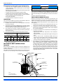
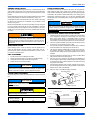
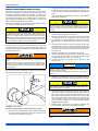
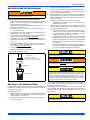
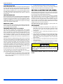
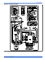
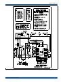
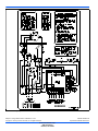
INSTALLATION MANUAL
R-410A OUTDOOR SPLIT-SYSTEM
HEAT PUMP
MODELS: 13 SEER & 14.5 SEER THG(D,F)/GHGD/THJ(D,F)/YHJ(D,F)/YHJR/THJR SERIES
1.5 TO 5 TONS – 1 & 3 PHASE
®
LIST OF SECTIONS
GENERAL . . . . . . . . . . . . . . . . . . . . . . . . . . . . . . . . . . . . . . . . . . . . . .1
SAFETY . . . . . . . . . . . . . . . . . . . . . . . . . . . . . . . . . . . . . . . . . . . . . . . .1
UNIT INSTALLATION . . . . . . . . . . . . . . . . . . . . . . . . . . . . . . . . . . . . .2
ORIFICE INSTALLATION . . . . . . . . . . . . . . . . . . . . . . . . . . . . . . . . . .5
TXV INSTALLATIONS . . . . . . . . . . . . . . . . . . . . . . . . . . . . . . . . . . . .5
EVACUATION . . . . . . . . . . . . . . . . . . . . . . . . . . . . . . . . . . . . . . . . . . .6
SYSTEM CHARGE . . . . . . . . . . . . . . . . . . . . . . . . . . . . . . . . . . . . . . 6
ELECTRICAL CONNECTIONS . . . . . . . . . . . . . . . . . . . . . . . . . . . . . 6
SYSTEM START-UP . . . . . . . . . . . . . . . . . . . . . . . . . . . . . . . . . . . . . 8
SYSTEM OPERATION . . . . . . . . . . . . . . . . . . . . . . . . . . . . . . . . . . . 10
INSTRUCTING THE OWNER . . . . . . . . . . . . . . . . . . . . . . . . . . . . . 12
WIRING DIAGRAM . . . . . . . . . . . . . . . . . . . . . . . . . . . . . . . . . . . . . 13
LIST OF FIGURES
Typical Installation with Required Clearances . . . . . . . . . . . . . . . . . . .2
Tubing Hanger . . . . . . . . . . . . . . . . . . . . . . . . . . . . . . . . . . . . . . . . . . .3
Underground Installation . . . . . . . . . . . . . . . . . . . . . . . . . . . . . . . . . . .3
Heat Protection . . . . . . . . . . . . . . . . . . . . . . . . . . . . . . . . . . . . . . . . . .4
Orifice Installation . . . . . . . . . . . . . . . . . . . . . . . . . . . . . . . . . . . . . . . . .5
Outdoor Unit Control Box - Single Phase . . . . . . . . . . . . . . . . . . . . . . .7
Outdoor Unit Control Box - Three Phase . . . . . . . . . . . . . . . . . . . . . . .7
Typical Field Wiring (Air Handler / Electrical Heat) (Single-Phase) . . .7
Typical Field Wiring (Air Handler / Electrical Heat) - (Three Phase) . .8
Heat Pump Flow Diagram . . . . . . . . . . . . . . . . . . . . . . . . . . . . . . . . . . 9
Time/Temp Control Module . . . . . . . . . . . . . . . . . . . . . . . . . . . . . . . . 9
Demand Defrost Control Module . . . . . . . . . . . . . . . . . . . . . . . . . . . . 9
Defrost Operation Curves . . . . . . . . . . . . . . . . . . . . . . . . . . . . . . . . . 11
Wiring Diagram - Single Phase (Demand Defrost) . . . . . . . . . . . . . . 13
Wiring Diagram - Single Phase (Time-Temp) . . . . . . . . . . . . . . . . . . 14
Wiring Diagram - Three Phase (Demand Defrost) . . . . . . . . . . . . . . 15
Wiring Diagram - Three Phase (Time-Temp) . . . . . . . . . . . . . . . . . . 16
LIST OF TABLES
R-410A Saturation Properties . . . . . . . . . . . . . . . . . . . . . . . . . . . . . . .9
TEST Input Functionality . . . . . . . . . . . . . . . . . . . . . . . . . . . . . . . . . .10
X/L Output Categories . . . . . . . . . . . . . . . . . . . . . . . . . . . . . . . . . . . 10
Defrost Initiate Curves . . . . . . . . . . . . . . . . . . . . . . . . . . . . . . . . . . . 11
SECTION I: GENERAL
The outdoor units are designed to be connected to a matching indoor
coil with sweat connect lines. Sweat connect units are factory charged
with refrigerant for a matching indoor coil plus 15 feet of field supplied
lines.
Matching indoor coils are available with a thermal expansion valve or
an orifice liquid feed sized for the most common usage. The orifice size
and/or refrigerant charge may need to be changed for some indoor-outdoor unit combinations, elevation differences, or total line lengths. Refer
to Application Data covering “General Piping Recommendations and
Refrigerant Line Length” (Part Number 247077).
SECTION II: SAFETY
This is a safety alert symbol. When you see this symbol on
labels or in manuals, be alert to the potential for personal
injury.
Understand and pay particular attention to the signal words DANGER,
WARNING, or CAUTION.
DANGER indicates an imminently hazardous situation, which, if not
avoided, will result in death or serious injury.
WARNING indicates a potentially hazardous situation, which, if not
avoided, could result in death or serious injury.
Improper installation may create a condition where the operation of
the product could cause personal injury or property damage.
Improper installation, adjustment, alteration, service, or maintenance can cause injury or property damage. Refer to this manual
for assistance or for additional information, consult a qualified contractor, installer, or service agency.
This product must be installed in strict compliance with the
enclosed installation instructions and any applicable local, state,
and national codes including, but not limited to building, electrical,
and mechanical codes.
INSPECTION
As soon as a unit is received, it should be inspected for possible damage during transit. If damage is evident, the extent of the damage
should be noted on the carrier’s delivery receipt. A separate request for
inspection by the carrier’s agent should be made in writing. See Local
Distributor for more information.
CAUTION indicates a potentially hazardous situation, which, if not
avoided may result in minor or moderate injury. It is also used to
alert against unsafe practices and hazards involving only property damage.
835961-UIM-B-0412
835961-UIM-B-0412
Requirements For Installing/Servicing R-410A Equipment
•
•
•
•
•
•
•
Gauge sets, hoses, refrigerant containers, and recovery system
must be designed to handle the POE type oils, and the higher
pressures of R-410A.
Manifold sets should be 800 psig high side and 250 psig low side
with 550 psig low side restart.
All hoses must have a 700 psig service pressure rating.
Leak detectors should be designed to detect HFC refrigerant.
Recovery equipment (including refrigerant recovery containers)
must be specifically designed to handle R-410A.
Do not use an R-22 TXV.
A liquid-line filter drier is required on every unit.
LIMITATIONS
The unit should be installed in accordance with all National, State, and
Local Safety Codes and the limitations listed below:
1.
2.
3.
4.
Limitations for the indoor unit, coil, and appropriate accessories
must also be observed.
The outdoor unit must not be installed with any duct work in the air
stream. The outdoor fan is the propeller type and is not designed
to operate against any additional external static pressure.
The maximum and minimum conditions for operation must be
observed to assure a system that will give maximum performance
with minimum service.
The maximum allowable line length for this product is 75 feet.
AIR TEMPERATURE AT
OUTDOOR COIL, °F
Min.
NOTICE
For multiple unit installations, units must be spaced a minimum of
24 inches apart (coil face to coil face).
If the unit is to be installed on a hot sun exposed roof or a black-topped
ground area, the unit should be raised sufficiently above the roof or
ground to avoid taking the accumulated layer of hot air into the outdoor
unit.
Provide an adequate structural support.
ADD-ON REPLACEMENT/RETROFIT
When this unit is being used as a replacement for an R-22 unit, it is
required that the outdoor unit, indoor coil, and metering device all be
replaced. The following steps should be performed in order to insure
proper system operation and performance. Line-set change out is also
recommended.
1.
2.
3.
•
AIR TEMPERATURE AT
INDOOR COIL, °F
Max.
Min.
•
Max.
DB
Cool
DB
Heat
DB
Cool
DB
Heat
WB
Cool
DB
Heat
WB
Cool
DB
Heat
50
-10
115
75
57
501
72
80
•
•
4.
1. Operation below this temperature is permissible for a short period of
time, during morning warm-up.
SECTION III: UNIT INSTALLATION
LOCATION
Before starting the installation, select and check the suitability of the
location for both the indoor and outdoor unit. Observe all limitations and
clearance requirements.
The outdoor unit must have sufficient clearance for air entrance to the
condenser coil, for air discharge, and for service access. See Figure 1.
60” OVERHEAD
CLEARANCE
Change-out of the indoor coil to an approved R-410A coil/ condensing unit combination with the appropriate metering device.
Change-out of the line-set when replacing an R-22 unit with an
R410-A unit is highly recommended to reduce cross-contamination of oils and refrigerants.
If change-out of the line set is not practical, then the following precautions should be taken.
Inspect the line set for kinks, sharp bends, or other restrictions,
and for corrosion.
Determine if there are any low spots which might be serving as oil
traps.
Flush the line set with a commercially available flush kit to
remove as much of the existing oil and contaminants as possible.
Install a suction line filter-drier to trap any remaining contaminants, and remove after 50 hours of operation.
If the outdoor unit is being replaced due to a compressor burnout,
then installation of a 100% activated alumina suction-line filter
drier in the suction-line is required, in addition to the factory
installed liquid-line drier. Operate the system for 10 hours. Monitor
the suction drier pressure drop. If the pressure drop exceeds 3
psig, replace both the suction-line and liquid-line driers. After a
total of 10 hours run time where the suction-line pressure drop has
not exceeded 3 psig, replace the liquid line drier, and remove the
suction-line drier. Never leave a suction-line drier in the system
longer than 50 hours of run time.
MINIMUM 18” SERVICE
ACCESS CLEARANCE
ON ONE SIDE
THERMOSTAT
WEATHERPROOF
DISCONNECT
SWITCH
NEC CLASS 1 WIRING
10” CLEARANCE
AROUND PERIMETER
TO FURNACE OR
AIR HANDLER
TERMINAL BLOCK
NEC CLASS 2 WIRING
TO INDOOR COIL
NOTE:
ALL OUTDOOR WIRING
MUST BE WEATHERPROOF.
CONTROL
ACCESS
PANEL
SEAL OPENING(S) WITH
PERMAGUM OR EQUIVALENT
FIGURE 1: Typical Installation with Required Clearances
2
Johnson Controls Unitary Products
835961-UIM-B-0412
GROUND INSTALLATION
PIPING CONNECTIONS
The unit may be installed at ground level on a solid base that will not
shift or settle, causing strain on the refrigerant lines and possible leaks.
Maintain the clearances shown in Figure 1 and install the unit in a level
position.
The outdoor unit must be connected to the indoor coil using field supplied refrigerant grade copper tubing that is internally clean and dry.
Units should be installed only with the tubing sizes for approved system
combinations as specified in Tabular Data Sheet. The charge given is
applicable for total tubing lengths up to 15 feet. See Application Data
Part Number 247077 for installing tubing of longer lengths and elevation
differences.
Normal operating sound levels may be objectionable if the unit is placed
directly under windows of certain rooms (bedrooms, study, etc.).
Condensate will drain from beneath the coil of the outdoor unit during
the defrost cycle. Normally this condensate may be allowed to drain
directly on the ground.
NOTICE
Elevate the unit sufficiently to prevent any blockage of the air entrances
by snow in areas where there will be snow accumulation. Check the
local weather bureau for the expected snow accumulation in your area.
Using a larger than specified line size could result in oil return problems. Using too small a line will result in loss of capacity and other
problems caused by insufficient refrigerant flow. Slope horizontal
vapor lines at least 1" every 20 feet toward the outdoor unit to facilitate proper oil return.
Isolate the unit from rain gutters to avoid any possible wash out of the
foundation.
PRECAUTIONS DURING LINE INSTALLATION
1.
The outdoor unit should not be installed in an area where mud or
ice could cause personal injury. Remember that condensate will
drip from the unit coil during heat and defrost cycles and that this
condensate will freeze when the temperature of the outdoor air is
below 32°F.
ROOF INSTALLATION
3.
When installing units on a roof, the structure must be capable of supporting the total weight of the unit, including a pad, lintels, rails, etc.,
which should be used to minimize the transmission of sound or vibration into the conditioned space.
UNIT PLACEMENT
1.
2.
3.
4.
2.
4.
5.
Provide a base in the pre-determined location.
Remove the shipping carton and inspect for possible damage.
Compressor tie-down bolts should remain tightened.
Position the unit on the base provided.
NOTICE
6.
7.
Heat pumps will defrost periodically resulting in water drainage. The
unit should not be located where water drainage may freeze and
create a hazardous condition - such as sidewalks and steps.
8.
Install the lines with as few bends as possible. Care must be taken
not to damage the couplings or kink the tubing. Use clean hard
drawn copper tubing where no appreciable amount of bending
around obstruction is necessary. If soft copper must be used, care
must be taken to avoid sharp bends which may cause a restriction.
The lines should be installed so that they will not obstruct service
access to the coil, air handling system, or filter.
Care must also be taken to isolate the refrigerant lines to minimize
noise transmission from the equipment to the structure.
The vapor line must be insulated with a minimum of 1/2" foam rubber insulation (Armaflex or equivalent). Liquid lines that will be
exposed to direct sunlight and/or high temperatures must also be
insulated.
Tape and suspend the refrigerant lines as shown. DO NOT allow
tube metal-to-metal contact. See Figure 2.
Use PVC piping as a conduit for all underground installations as
shown in Figure 3. Buried lines should be kept as short as possible
to minimize the build up of liquid refrigerant in the vapor line during
long periods of shutdown.
Pack fiberglass insulation and a sealing material such as permagum around refrigerant lines where they penetrate a wall to reduce
vibration and to retain some flexibility.
See Form 247077 for additional piping information.
Sheet Metal Hanger
LIQUID LINE FILTER-DRIER
Liquid
Line
The heat pumps have a solid core bi-flow filter/drier located on the liquid
line.
Incorrect
NOTICE
Replacements for the liquid line drier must be exactly the same as
marked on the original factory drier. See Source 1 for O.E.M.
replacement driers.
Tape
Correct
Insulated Vapor Line
FIGURE 2: Tubing Hanger
Failure to do so or using a substitute drier or a granular type may
result in damage to the equipment.
TO INDOOR COIL
LIQUID LINE
PVC
Filter-Drier
Source 1 Part No.
Apply with Models
S1-52636219000
All
TO OUTDOOR UNIT
INSULATED
CAP
VAPOR LINE
CONDUIT
*As listed on the “Energy Guide yellow sticker on the unit.
FIGURE 3: Underground Installation
Johnson Controls Unitary Products
3
835961-UIM-B-0412
PRECAUTIONS DURING BRAZING OF LINES
All outdoor unit and evaporator coil connections are copper-to-copper
and should be brazed with a phosphorous-copper alloy material such
as Silfos-5 or equivalent. DO NOT use soft solder. The outdoor units
have reusable service valves on both the liquid and vapor connections.
The total system refrigerant charge is retained within the outdoor unit
during shipping and installation. The reusable service valves are provided to evacuate and charge per this instruction.
2.
3.
Serious service problems can be avoided by taking adequate precautions to assure an internally clean and dry system.
Dry nitrogen should always be supplied through the tubing while it
is being brazed, because the temperature is high enough to cause
oxidation of the copper unless an inert atmosphere is provided. The
flow of dry nitrogen should continue until the joint has cooled.
Always use a pressure regulator and safety valve to insure that only
low pressure dry nitrogen is introduced into the tubing. Only a small
flow is necessary to displace air and prevent oxidation.
PRECAUTIONS DURING BRAZING SERVICE VALVE
Do not install any coil in a furnace which is to be operated during
the heating season without attaching the refrigerant lines to the coil.
The coil is under 30 to 35 psig inert gas pressure which must be
released to prevent excessive pressure build-up and possible coil
damage.
4.
5.
6.
Precautions should be taken to prevent heat damage to service valve
by wrapping a wet rag around it as shown in Figure 4. Also, protect all
painted surfaces, insulation, and plastic base during brazing. After brazing cool joint with wet rag.
7.
8.
This is not a backseating valve. The service access port has a
valve core. Opening or closing valve does not close service access
port.
If the valve stem is backed out past the chamfered retaining wall,
the O-ring can be damaged causing leakage or system pressure
could force the valve stem out of the valve body possibly causing
personal injury.
Valve can be opened by removing the plunger cap and fully inserting a
hex wrench into the stem and backing out counter-clockwise until valve
stem just touches the chamfered retaining wall.
Braze the liquid line to the liquid valve at the outdoor unit. Be sure
to wrap the valve body with a wet rag. Allow the nitrogen to continue flowing. Refer to the Tabular Data Sheet for proper liquid line
sizing.
Go to “SECTION IV” or “SECTION V” for orifice or TXV Installation
depending on application.
9.
Braze the liquid line to the evaporator liquid connection. Nitrogen
should be flowing through the evaporator coil.
Slide the grommet away from the vapor connection at the indoor
coil. Braze the vapor line to the evaporator vapor connection. After
the connection has cooled, slide the grommet back into original
position. Refer to the Tabular Data Sheet for proper vapor line sizing.
Protect the vapor valve with a wet rag and braze the vapor line
connection to the outdoor unit. The nitrogen flow should be exiting
the system from the vapor service port connection. After this connection has cooled, remove the nitrogen source from the liquid fitting service port.
Replace the Schrader core in the liquid and vapor valves.
Leak test all refrigerant piping connections including the service
port flare caps to be sure they are leak tight. DO NOT OVERTIGHTEN (between 40 and 60 inch - lbs. maximum).
Evacuate the vapor line, evaporator, and the liquid line to 500
microns or less.
NOTICE
Line set and indoor coil can be pressurized to 250 psig with dry
nitrogen and leak tested with a bubble type leak detector. Then
release the nitrogen charge.
Do not use the system refrigerant in the outdoor unit to purge or
leak test.
10. Replace cap on service ports. Do not remove the flare caps from
the service ports except when necessary for servicing the system.
Do not connect manifold gauges unless trouble is suspected.
Approximately 3/4 ounce of refrigerant will be lost each time a standard manifold gauge is connected.
FIGURE 4: Heat Protection
11. Release the refrigerant charge into the system. Open both the liquid and vapor valves by removing the plunger cap and with an
allen wrench back out counter-clockwise until valve stem just
touches the chamfered retaining wall. If the service valve is a ball
valve, use a cresent wrench to turn valve stem one-quarter turn
counterclockwise to open. Do not overturn or the valve stem may
break or become damaged. See “PRECAUTIONS DURING
BRAZING SERVICE VALVE”.
12. Replace plunger cap finger tight, then tighten an additional 1/12
turn (1/2 hex flat). Cap must be replaced to prevent leaks.
Connect the refrigerant lines using the following procedure:
1.
Remove the cap and Schrader core from both the liquid and vapor
service valve service ports at the outdoor unit. Connect low pressure nitrogen to the liquid line service port.
Never attempt to repair any brazed connections while the system is
under pressure. Personal injury could result.
See "System Charge” section for checking and recording system
charge.
4
Johnson Controls Unitary Products
835961-UIM-B-0412
SECTION IV: ORIFICE INSTALLATION
Failure to install Schrader Valve Core on orifice applications could
result in total refrigerant loss of the system!
Install Schrader Valve Core and Orifice as follows:
1.
Relieve the holding charge by depressing the Schrader valve stem
located in the end of the liquid line. Cut the spundown copper to
allow installation of the suction line.
2. Slide indoor coil out of cabinet far enough to gain access to equalizer fitting on the suction line.
3. After holding charge is completely discharged remove black plastic cap on equalizer fitting.
4. Install Schrader Valve Core supplied with the outdoor unit into
equalizer fitting using a valve core tool.
5. Loosen and remove the liquid line fitting from the orifice distributor
assembly. Note that the fitting has right hand threads.
6. Install proper size orifice supplied with outdoor unit. Refer to supplied Tabular Data Sheet for specific orifice size and indoor coil
match up.
7. After orifice is installed reinstall the liquid line to the top of the orifice distributor assembly. Hand tighten and turn an additional 1/8
turn to seal. Do not over tighten fittings.
8. Leak test system.
9. Replace black plastic cap on equalizer fitting.
10. Slide indoor coil back into cabinet.
LIQUID LINE
SWIVEL COUPLING
(This fitting is a right-hand thread,
turn counter-clockwise to remove)
3.
4.
5.
6.
7.
Loosen and remove distributor cap seal.
Install the thermal expansion valve to the orifice distributor assembly with supplied fittings. Hand tighten and turn an additional 1/4
turn to seal. Do not overtighten fittings.
Install the liquid line to the top of the thermal expansion valve with
fitting supplied with the liquid line. Hand modify the liquid line to
align with casing opening. Hand tighten the liquid line and an additional 1/4 turn to seal.
Install the TXV equalizer line into the vapor line as follows:
a. Hand tighten the 1/4” SAE nut to the Schrader fitting and an
additional 1/3 turn to seal.
Install the TXV bulb to the vapor line near the equalizer line, using
the bulb clamp(s) furnished with the TXV assembly. Ensure the
bulb is making maximum contact.
a. Bulb should be installed on a horizontal run of the vapor line if
possible. On lines under 7/8" O.D. the bulb may be installed
on top of the line. With 7/8" O.D. and over, the bulb should be
installed at the position of about 2 or 10 o'clock.
b.
If bulb installation is made on a vertical run, the bulb should
be located at least 16” (40.6 cm) from any bend, and on the
tubing sides opposite the plane of the bend. The bulb should
be positioned with the bulb tail at the top, so that the bulb acts
as a reservoir.
c.
Bulb should be insulated using thermal insulation provided to
protect it from the effect of the surrounding ambient temperature. Cover completely to insulate from air-stream.
In all cases, mount the TXV bulb after vapor line is brazed and has
had sufficient time to cool.
Schrader valve core MUST NOT be installed with TXV installation.
Poor system performance or system failure could result.
ORIFICE
DISTRIBUTOR
FIGURE 5: Orifice Installation
SECTION V: TXV INSTALLATIONS
For installations requiring a TXV, the following are the basic steps for
installation. For detailed instructions, refer to the Installation Instructions
accompanying the TXV kit.
Install TXV kit as follows:
1.
2.
Relieve the holding charge by depressing the Schrader valve stem
located in the end of the liquid line. Cut the spundown copper to
allow installation of the suction line.
After holding charge is completely discharged, loosen and remove
the Schrader cap seal.
Johnson Controls Unitary Products
Dry nitrogen should always be supplied through the tubing while it
is being brazed, because the temperature is high enough to cause
oxidation of the copper unless an inert atmosphere is provided. The
flow of dry nitrogen should continue until the joint has cooled.
Always use a pressure regulator and safety valve to insure that only
low pressure dry nitrogen is introduced into the tubing. Only a small
flow is necessary to displace air and prevent oxidation.
All connections to be brazed are copper-to-copper and should be
brazed with a phosphorous-copper alloy material such as Silfos-5 or
equivalent. DO NOT use soft solder.
Install the TXV bulb to the vapor line near the equalizer line, using the
two bulb clamps furnished with the TXV assembly. Ensure the bulb is
making maximum contact. Refer to TXV installation instruction for view
of bulb location.
In all cases, mount the TXV bulb after vapor line is brazed and has
had sufficient time to cool.
5
835961-UIM-B-0412
SECTION VI: EVACUATION
It will be necessary to evacuate the system to 500 microns or less. If a
leak is suspected, leak test with dry nitrogen to locate the leak. Repair
the leak and test again.
Refrigerant charging should only be carried out by a qualified air
conditioning contractor.
To verify that the system has no leaks, simply close the valve to the vacuum pump suction to isolate the pump and hold the system under vacuum. Watch the micron gauge for a few minutes. If the micron gauge
indicates a steady and continuous rise, it’s an indication of a leak. If the
gauge shows a rise, then levels off after a few minutes and remains
fairly constant, its an indication that the system is leak free but still contains moisture and may require further evacuation if the reading is
above 500 microns.
Compressor damage will occur if system is improperly charged. On
new system installations, charge system per tabular data sheet for
the matched coil and follow guidelines in this instruction.
SECTION VII: SYSTEM CHARGE
The factory charge in the outdoor unit includes enough charge for the
unit, a 15 ft. (4.6 m) line set, and the smallest indoor coil match-up.
Some indoor coil matches may require additional charge. See tabular
data sheet provided in unit literature packet for charge requirements.
IT IS UNLAWFUL TO KNOWINGLY VENT, RELEASE OR DISCHARGE REFRIGERANT INTO THE OPEN AIR DURING
REPAIR, SERVICE, MAINTENANCE OR THE FINAL DISPOSAL
OF THIS UNIT.
SECTION VIII: ELECTRICAL
CONNECTIONS
Do not leave the system open to the atmosphere.
GENERAL INFORMATION & GROUNDING
The “TOTAL SYSTEM CHARGE” must be permanently stamped on the
unit data plate.
Check the electrical supply to be sure that it meets the values specified
on the unit nameplate and wiring label.
Total system charge is determined as follows:
Power wiring, control (low voltage) wiring, disconnect switches and over
current protection must be supplied by the installer. Wire size should be
sized per NEC requirements.
1.
2.
3.
Determine outdoor unit charge from tabular data sheet.
Determine indoor coil adjustment from tabular data sheet.
Calculate the line charge using the tabular data sheet if line length
is greater than 15 feet (4.6 m).
4. Total system charge = item 1 + item 2 + item 3.
5. Permanently stamp the unit data plate with the total amount of
refrigerant in the system.
Use the following charging method whenever additional refrigerant is
required for the system charge.
If a calibrated charging cylinder or accurate weighing device is available, add refrigerant accordingly. Otherwise, model-specific charging
charts are provided on the access panel of the unit.
All field wiring must USE COPPER CONDUCTORS ONLY and be
in accordance with Local, National, Fire, Safety & Electrical Codes.
This unit must be grounded with a separate ground wire in accordance with the above codes.
The complete connection diagram and schematic wiring label is located
on the inside surface of the unit service access panel.
FIELD CONNECTIONS POWER WIRING
1.
DO NOT attempt to pump “Total System Charge” into outdoor unit
for maintenance, service, etc. This may cause damage to the compressor and/or other components. the outdoor unit only has enough
volume for the factory charge, not the “Total System Charge”.
2.
3.
4.
5.
6
Install the proper size weatherproof disconnect switch outdoors
and within sight of the unit.
Remove the screws from the control box cover and remove from
unit.
Run power wiring from the disconnect switch to the unit.
Route wires from disconnect through power wiring opening provided and into the unit control box as shown in Figures 6 or 7.
Install the proper size time-delay fuses or circuit breaker, and
make the power supply connections.
Johnson Controls Unitary Products
835961-UIM-B-0412
Contactor
Contactor
Defrost
Control
Board
Low
Voltage
Box
Reversible High
Voltage Conduit Plate
5.
“Fingered”
Bushing
Reversible High
Voltage Conduit Plate
Fan
Capacitor
Ground
Lug
FIGURE 7: Outdoor Unit Control Box - Three Phase
FIELD CONNECTIONS CONTROL WIRING
3.
4.
Low
Voltage
Box
Start Capacitor
(Optional)
Ground
Lug
FIGURE 6: Outdoor Unit Control Box - Single Phase
2.
Fan
Relay
Dual
Run/Fan
Capacitor
“Fingered”
Bushing
1.
Defrost
Control
Board
Start
Relay
(Optional)
6.
Route low voltage wiring into bottom of control box as shown in
Figures 6 or 7. Make low voltage wiring connections inside the low
voltage box per Figures 8-9.
The complete connection diagram and schematic wiring label is
located on the inside surface of the unit service access panel.
Replace the control box cover removed in Step 2.
All field wiring to be in accordance with national electrical codes
(NEC) and/or local-city codes.
Mount the thermostat about 5 ft. above the floor, where it will be
exposed to normal room air circulation. Do not place it on an outside wall or where it is exposed to the radiant effect from exposed
glass or appliances, drafts from outside doors or supply air grilles.
Route the 24-volt control wiring (NEC Class 2) from the outdoor
unit to the indoor unit and thermostat.
NOTICE
To eliminate erratic operation, seal the hole in the wall at the thermostat with permagum or equivalent to prevent air drafts affecting
the operation of in the thermostat.
A Start Assist Kit is available and recommended for long line set
applications or in areas of known low voltage problems.
ALL FIELD WIRING TO BE IN ACCORDANCE WITH ELECTRIC CODE (NEC) AND/OR LOCAL CODES
OUTDOOR UNIT
INDOOR UNIT
THERMOSTAT
3,4
LOW VOLTAGE TERMINAL BLOCK
IN AIR HANDLER WITH ELECTRIC HEAT
R
B or C
Y
O
W
L or X
G
T2
2
E
R
B or C
Y
O
W2
FIELD
INSTALLED
JUMPER
1
JUMPER TERMINALS E AND W TO HEAT
ON FIRST STAGE DURING EMERGENCY HEAT.
2
TERMINAL NOT USED ON ALL THERMOSTATS.
POWER WIRING
24V CONTROL WIRING
(NEC CLASS 2)
3
4
G
W1
1
GND.
LUG
DEFROST
CONTROL
RED
R
BLK
C
YEL Y
ORG
O
WHT
W
PUR X
CONTACTOR
T3
T2
M
T1
L3
L2
L1
GND.
SCREW
BRN W1/66
POWER
SUPPLY
208/230-3-60
460-3-60
POWER WIRING
208/230-3-60
460-3-60
CHECK THE LOW VOLTAGE TERMINAL BLOCK ON THE INDOOR UNIT FOR THE ACTUAL ARRANGEMENT OF THE TERMINALS.
CONNECT POWER WIRING TO TERMINAL BLOCK 3TB ON UNITS WITHOUT ELECTRIC HEAT OR CIRCUIT BREAKER.
FIGURE 8: Typical Field Wiring (Air Handler / Electrical Heat) - (Three Phase)
Johnson Controls Unitary Products
7
835961-UIM-B-0412
ALL FIELD WIRING TO BE IN ACCORDANCE WITH ELECTRIC CODE (NEC) AND/OR LOCAL CODES
OUTDOOR UNIT
INDOOR UNIT
THERMOSTAT
LOW VOLTAGE TERMINAL BLOCK 3,4
IN AIR HANDLER WITH ELECTRIC HEAT
DEFROST
CONTROL
R
R
RED
B or C
C
BLK
Y
Y
YEL
O
O
ORG
W
W2
WHT
W
PUR
X/L
L or X
G
2
T
E
2
1 JUMPER TERMINALS E AND W TO HEAT
ON FIRST STAGE DURING EMERGENCY HEAT.
2 TERMINAL NOT USED ON ALL THERMOSTATS.
POWER WIRING
24V CONTROL WIRING
(NEC CLASS 2)
CONTACTOR
C
Y
T2
T1
M
O
L2
L1
GND.
SCREW
BRN W1/66
G
1 FIELD
INSTALLED
JUMPER
R
W1
BK
DEHUMIDIFICATION CONTROL CONNECTION
(Humidistat* Jumper must be removed)
GND.
LUG
POWER WIRING
208/230-1-60
230-1-50
CIRCUIT
BREAKER***
3 CHECK THE LOW VOLTAGE TERMINAL BLOCK ON THE INDOOR UNIT FOR THE ACTUAL ARRANGEMENT OF THE TERMINALS.
4 CONNECT POWER WIRING TO TERMINAL BLOCK 3TB ON UNITS WITHOUT ELECTRIC HEAT OR CIRCUIT BREAKER.
FIGURE 9: Typical Field Wiring (Air Handler / Electrical Heat) (Single-Phase)
DEHUMIDIFICATION CONTROL
SECTION IX: SYSTEM START-UP
A dehumidification control accessory 2HU06700124 may be used with
variable speed air handlers or furnaces in high humidity areas. This
control works with the variable speed indoor unit to provide cooling at a
reduced air flow, lowering evaporator temperature and increasing latent
capacity. The humidistat in this control opens the humidistat contacts on
humidity rise. To install, refer to instructions packaged with the accessory. Prior to the installation of the dehumidification control, the jumper
across the HUMIDISTAT terminals on the indoor variable speed air handler or furnace CFM selection board must be removed.
ENERGIZE CRANKCASE HEATER
During cooling, if the relative humidity in the space is higher than the
desired set point of the dehumidification control, the variable speed
blower motor will operate at lower speed until the dehumidification control is satisfied. A 40-60% relative humidity level is recommended to
achieve optimum comfort.
If a dehumidification control is installed, it is recommended that a minimum air flow of 325 cfm/ton be supplied at all times.
For connection diagrams for all UPG equipment refer to “Low Voltage
System Wiring” document available online at www.upgnet.com in the
Product Catalog Section.
If this unit is equipped with a crankcase heater for the compressor, a
warning label with an adhesive back is supplied in the unit installation
instruction packet. This label should be attached to the field supplied
disconnect switch where it will be easily seen.
In order to energize the crankcase heater, set the indoor cooling thermostat to the OFF position. Close the line power disconnect to the unit.
An attempt to start the compressor without at least 8 hours of
crankcase heat will damage the compressor.
WITH POWER TO UNIT AND THERMOSTAT IN COOLING
POSITION:
1.
In the cooling cycle, discharge gas is pumped to the outdoor coil
which is the condenser. The indoor coil is the evaporator.
2.
If fan switch is in ON position, a circuit is made through blower
relay to provide continuous blower operation.
3.
With fan switch in AUTO position, a circuit is made from thermostat cooling contact through blower relay to provide blower operation.
4.
System will cycle with thermostat demand to provide cooling as
needed.
CFM SELECTION BOARD SETTINGS
For proper system operation the CFM Selection control jumpers must
be set properly.
Refer to the Tabular Data Sheet for the recommended air flow settings
for each size condensing unit.
Set the cooling speed per the instructions for the air handler or furnace
by selecting the correct COOL and ADJ taps. Verify the airflow using
the LED display on the CFM selection board.
8
Johnson Controls Unitary Products
835961-UIM-B-0412
TABLE 1: R-410A Saturation Properties
Temp °F
Pressure
PSIG
Temp °F
Pressure
PSIG
Temp °F
Pressure
PSIG
Temp °F
Pressure
PSIG
Temp °F
Pressure
PSIG
45
130
60
170
75
217
90
274
105
341
46
132
61
173
76
221
91
278
106
345
47
135
62
176
77
224
92
282
107
350
48
137
63
179
78
228
93
287
108
355
49
140
64
182
79
232
94
291
109
360
50
142
65
185
80
235
95
295
110
365
51
145
66
188
81
239
96
299
111
370
52
147
67
191
82
243
97
304
112
375
53
150
68
194
83
247
98
308
113
380
54
153
69
197
84
250
99
313
114
385
55
156
70
201
85
254
100
317
115
391
56
158
71
204
86
258
101
322
116
396
57
161
72
207
87
262
102
326.
117
401
58
164
73
211
88
266
103
331
118
407
59
167
74
214
89
270
104
336
119
412
CHARGE COMPENSATOR
(Empty in cooling / full in heating)
(Not included in all Units)
FIELD CONNECTED LINE
INDOOR COIL
OUTDOOR
COIL
4-WAY
REVERSING
VALVE
FILTER DRYER
(Solid core)
SUCTION
ACCUMULATOR
COMPRESSOR
BI-FLOW
TXV/CHECK
VALVE OR ORIFICE (Heating)
LIQUID
SENSOR
BI-FLOW
TXV/CHECK
VALVE (Cooling) **
FIGURE 10: Heat Pump Flow Diagram
MIN. SEL
90
60
30
RUNTIME
TEST
30
90
AMBG
X/L
R
C
Y
O
AMBIENT
ALTERNATE
CONFIGURATION
R
C
Y
DEMAND
DEFROST CURVE
SELECTION JUMPER
X/L
R
C
COIL G
Test
RUN TIME
COIL
XL
R
TEST
TEST
P
1
2
3
4
RUN TIME
XL
O
W
C
Y
Y
W
O
W1/66
O
W1/66
PRESSURE
DFST
M
VALVE
SWITCH
T’STAT
M
COND.
FAN
REV
PRESSURE
VALVE
SWITCH
FAN
REV
W1/66
HIGH VOLTAGE
K3
K1
K2
W
COND
W W1/66
R3
M
FIGURE 12: Demand Defrost Control Module
PRESSURE
COMP RLY
DFST
OM
REV
ALTERNATE
FIGURE 11: Time/Temp Control Module
Johnson Controls Unitary Products
9
835961-UIM-B-0412
SECTION V: SYSTEM OPERATION
ANTI-SHORT CYCLE DELAY
The control includes a five-minute anti-short cycle delay (ASCD) timer
to prevent the compressor from short cycling after a power or thermostat signal interruption. The ASCD timer is applied when the control is
first powered from the indoor unit thermostat and immediately following
the completion of a compressor run cycle. The compressor and the outdoor fan will not operate during the five minutes that the timer is active.
The ASCD timer can be bypassed by connecting the TEST terminals
for three seconds while the thermostat is calling for compressor operation (Y input signal energized).
LOW VOLTAGE DETECTION
The control monitors the transformer secondary (24 VAC) voltage and
provides low voltage protection for the heat pump and its components.
In particular, the control prevents contactor chatter during low voltage
conditions. If the voltage drops below approximately 19 VAC, the control will continue to energize any relays that are already energized but
will not energize any additional relays until the voltage level increases.
If the voltage drops below approximately 16 VAC, the control will immediately de-energize the relay outputs and will not energize any relays
until the voltage level increases.
TEST INPUT
TABLE 2: TEST Input Functionality
Duration of Connection (seconds)
Time-Temp
Demand Defrost
Less than 2
Less than 2
More than 9
The defrost control is a time/temp. control which includes a field-selectable (tap located at board edge) time period between defrost cycle (30,
60, and 90 minutes). The jumper is factory set at 60 minutes. See Figure 13.
The electronic timer and the defrost cycle will start only when the contactor is energized and the defrost thermostat is closed. The defrost
thermostat is closed when the liquid temperature falls below approximately 31° F.
The defrost mode is identical to the cooling mode except that the outdoor fan motor stops and the first stage of heat is turned on through W1
/ 66 to continue warming the conditioned space.
The defrost cycle will be terminated when the defrost thermostat is
opened at 55° F or 10 minutes of compressor accumulated run time,
whichever comes first.
NOTICE
The defrost thermostat delay will make the coil temperature about
75-80° F. Please note that the timer will stop the circuit when R to Y
is disconnected.
Demand Defrost (13 Seer 1.5 ton, 14.5 Seer 1.5-4 Ton)
The control includes a TEST input connector that can be used for various testing functions during installation and service. The TEST input
connector is shown in Figures 11 & 12. The following table summarizes
the behavior of the control when the two TEST pins are connected.
More detailed descriptions of the various functions are included in other
sections of this document.
2-9
DEFROST OPERATION
Time/Temperature Defrost (13 Seer 2-5 Ton)
2-6
More than 6
Connection removed
Connection not removed
Control Behavior
No response
Bypass ASCD. If Y is present
and pressure switch is closed,
contactors will be energized.
Clear lockout
Initiate defrost cycle. (Demand
only: Energize X/L with active
defrost curve flash code)
Terminate defrost as normal
Continue defrost cycle (Demand
only: and X/L flash code) until
TEST connection removed.
FAULT CODE DISPLAY
X/L Output
The X/L terminal of the heat pump control is typically connected to the
X/L input of the room thermostat. The thermostat uses this signal to
notify the homeowner of a problem with the heat pump using an LED or
LCD display. When the control energizes the X/L terminal, the thermostat displays the flash code so the homeowner can see it.
TABLE 3: X/L Output Categories
Condition
X/L
Pressure Switch lockout - last mode of operation was heating 2 flashes
Pressure Switch lockout - last mode of operation was defrost 3 flashes
Incorrect Defrost Curve - jumper selection
On
The control maintains proper airflow through the outdoor coil during
heating operation by melting frost and ice that may form on the coil.
Frost may accumulate unevenly in different sections of the coil because
of the arrangement of the refrigeration circuit within the coil. The control
may initiate a defrost cycle even when the coil is not completely covered with frost. This is normal operation.
The control regulates the defrost operation of the heat pump based on
accumulated compressor run time, outdoor coil temperature, and outdoor ambient temperature. The control will cause the unit to operate in
the normal heating mode until it determines that a defrost cycle is
needed.
All defrost timings are based on accumulated compressor run time.
Operation
The defrost mode is equivalent to the cooling mode except that the outdoor fan motor is de-energized. The control shall do the following to initiate a defrost cycle.
• De-energize the outdoor fan.
• Energize the reversing valve.
• Energize the auxiliary heat output through the W1/66 terminal.
• Begin the maximum defrost cycle length timer.
If the call for heating (Y) is removed from the control during the defrost
cycle, it will terminate the defrost cycle and de-energize the compressor. The control will also stop the defrost cycle length timer but not reset
it. When the control receives another call for heating, it will restart the
defrost cycle and the timer at the point at which the call for heating was
removed. This will happen only if the liquid line temperature conditions
allow defrost to occur.
Defrost Curves
The control uses a set of defrost curve parameters that are selected
using the defrost curve selection jumper. The location of the defrost
curve selection jumper is shown in Figure 13. Table 4 shows the jumper
position that is appropriate for each heat pump model. Jumper position
4 is not used and the control will not allow the compressor to operate
when the jumper is in this position.
When the control locks out the compressor because of a pressure
switch lockout, it will energize the X/L output as shown in Table 3. The
control has a three second delay between fault code flashes.
If the conditions above exist during cooling mode, the system could be
in the loss of charge condition.
10
Johnson Controls Unitary Products
835961-UIM-B-0412
Defrost Curve Selection
The factory will place the defrost curve selection jumper in the P position or in a numbered position appropriate for the specific heat pump
model. You should not have to change the defrost curve selection
jumper during initial installation.
If the jumper is inadvertently moved, it should be placed in the appropriate numbered location based on the model number and Table 4. The
control will also not energize the compressor if the defrost curve selection jumper is in a numbered position that is not described in Table 4 or
if the defrost curve selection jumper is missing. The control will display
the proper fault code when a defrost curve jumper error is present. The
control will display the active defrost curve using the X/L terminal when
the heat pump is operating in a defrost cycle that has been forced using
the TEST inputs.
For instance, the X/L output will be energized with two flashes when
defrost curve 2 is active. The control only reads the jumper input when
the Y and W thermostat inputs are de-energized. If a jumper position is
changed while either of these inputs is energized, the control will not act
upon the jumper changes until the thermostat calls are de-energized or
power (24 VAC) to the control is cycled.
Defrost Cycle Initiation
The control will allow the heat pump to operate in the heating mode until
the combination of outdoor ambient and outdoor coil temperatures indicate that a defrost cycle is necessary.
The control will initiate a defrost cycle when the liquid line temperature
is below the initiate point for the measured ambient temperature (See
Figure 13) continuously for 4-1/2 minutes. This delay eliminates unnecessary defrost cycles caused by refrigeration surges such as those that
occur at the start of a heating cycle.
The control will initiate a defrost cycle every 6 hours (accumulated compressor run time) to recirculate refrigerant lubricants. This forced
defrost timer will be reset and restarted following the completion or termination of a defrost cycle.
The control will also initiate a defrost cycle when the TEST terminals
are shorted. This feature allows an installer or service technician to start
a defrost cycle immediately as required. When the TEST terminals are
shorted for more than six seconds with a Y input energized and the
pressure switch input is closed, the ASCD will be bypassed and the
compressor and the W1/66 terminal to auxiliary heat will be energized.
When the TEST inputs are used to force a defrost cycle, the control will
ignore the state of the liquid line temperature and outdoor ambient temperature inputs. The coil does not have to be cold and the outdoor temperature does not have to be within a certain range for the heat pump to
be forced into a defrost cycle. After the TEST input jumper is removed,
the defrost mode will be terminated as normal. The defrost cycle length
timer will not be started until the TEST input is removed. If the TEST terminals remain shorted, the control will keep the unit in defrost mode.
Defrost Inhibition
The control will not initiate a defrost cycle if the liquid line temperature is
above 40°F unless the defrost cycle is forced using the TEST input.
The control will also prevent a defrost cycle from being initiated too
soon after the initiation of the previous defrost cycle. When power is
applied to the control and after the completion or termination of each
defrost cycle, the control will start a 40-minute timer. When this timer
expires, the control will allow another defrost cycle when needed. The
timer is based on accumulated compressor run time.
Defrost Termination
The control will terminate the defrost cycle immediately after the liquid
line temperature reaches 80°F or after eight minutes of defrost operation.
The control will do the following to terminate a defrost cycle:
•
•
•
•
Energize the outdoor fan.
De-energize the reversing valve.
De-energize the auxiliary heat output through the W1/66 terminal.
Reset and restart the 40-minute defrost inhibit timer.
Compressor Delay
When Defrost Jumper Position #2 is selected the compressor is shut
down for 30 seconds entering and exiting defrost mode. This delay is
present in normal operation but is not present when the TEST pins are
shorted to force a defrost cycle. Position #1 is recommended for reciprocating compressors, and Position #2 is recommended for scroll compressors.
TABLE 4: Defrost Initiate Curves
Defrost Curve Selection
Jumper Position
1
2
3
4
All Other Models
YHJR, THJR,THRD, GHRD
YHJD, YHJF, THJD, THJF,
CHJD, CHJF, LHJD, LHJF
THGD, GHGD
None
None
Jumper settings 1-3 are different defrost curve settings. 4 & P will not work in application.
REGION C
LIQUID LINE (COIL) TEMPERATURE
TERMINATE CURVE
Defrost Terminated
REGION E
REGION D
No call for defrost
Time Defrost (6 hour) prevented
Defrost prevented from starting
INHIBIT CURVE
REGION B
No call for Defrost
Time Defrost (6 hour) allowed
REGION A
Call for Defrost
E
RV
TE
IA
CU
T
NI
I
AMBIENT TEMPERATURE
FIGURE 13: Defrost Operation Curves
Johnson Controls Unitary Products
11
835961-UIM-B-0412
COOLING OPERATION
During cooling operation, the control will receive thermostat signals at
the Y and O input terminals. The control will energize the M compressor
output terminal. This signal energizes the coil of the compressor contactor causing the compressor to run. The control also delivers power to
the COND FAN terminals causing the outdoor fan to operate. The control energizes the REV VALVE terminal with 24VAC to switch the
reversing valve.
HEATING OPERATION
During normal heating mode, the control will receive a thermostat signal
at the Y input terminal. The control will energize the M compressor output terminal. This signal energizes the coil of the compressor contactor
causing the compressor to run. The control also delivers power to the
COND FAN terminals causing the outdoor fan to operate. The reversing
valve is not energized in heating mode.
EMERGENCY HEAT
When the thermostat calls for emergency heat operation (W signal without a Y signal), the control will de-energize the compressor and energize the W1/66 terminal immediately.
PRESSURE SWITCH FAULT & LOCKOUT
The heat pump is equipped with a pressure switch, loss of charge
switch and an over temp switch (units equipped with scroll compressor)
that are connected to the control at the pressure switch terminals. If one
of these switches input opens for more than 40 milliseconds, the control
will de-energize the compressor. If the switch closes and a thermostat
call for compressor operation is present, the control will apply the fiveminute anti-short cycle delay timer and start the compressor when the
timer expires.
When the compressor is started following a switch fault, the control will
start a six-hour timer based on accumulated compressor run time. If the
control senses another opening of the switch before the timer expires, it
will cause a soft lockout condition. The second opening of the switch
must be greater than 160 milliseconds for the lockout to occur. If the
second opening is between 40 and 160 milliseconds, the control will deenergize the compressor but not cause a soft lockout condition. If the
control does not sense a second switch opening before the six-hour
timer expires, the timer and counter will be reset.
During the soft lockout mode, the control will de-energize the compressor and energize the X/L output with the appropriate flash code.
The control will reset the soft lockout condition when any of the following occur following removal of the fault condition.
1.
12
Power is cycled to the R or Y inputs of the control. This will cause
the soft lockout condition to be reset when the thermostat is satisfied or when the thermostat is set to SYSTEM OFF and back to
HEAT or COOL mode.
2. The TEST terminals are shorted for more than two seconds.
When the soft lockout condition is reset, the control will stop displaying
the fault code and will respond to thermostat inputs normally.
SECTION VI: INSTRUCTING THE OWNER
Assist owner with processing warranty cards and/or online registration.
Review Owners Guide and provide a copy to the owner and guidance
on proper operation and maintenance. Instruct the owner or the operator how to start, stop and adjust temperature setting.
When applicable, instruct the owner that the compressor is equipped
with a crankcase heater to prevent the migration of refrigerant to the
compressor during the OFF cycle. The heater is energized only when
the unit is not running. If the main switch is disconnected for long periods of shut down, do not attempt to start the unit until 8 hours after the
switch has been connected. This will allow sufficient time for all liquid
refrigerant to be driven out of the compressor.
The installer should also instruct the owner on proper operation and
maintenance of all other system components.
MAINTENANCE
1.
2.
3.
4.
5.
Dirt should not be allowed to accumulate on the outdoor coils or
other parts in the air circuit. Clean as often as necessary to keep
the unit clean. Use a brush, vacuum cleaner attachment, or other
suitable means.
The outdoor fan motor is permanently lubricated and does not
require periodic oiling.
If the coil needs to be cleaned, it should be washed with Calgon
Coilclean (mix one part Coilclean to seven parts water). Allow
solution to remain on coil for 30 minutes before rinsing with clean
water. Solution should not be permitted to come in contact with
painted surfaces.
Refer to the furnace or air handler instructions for filter and blower
motor maintenance.
The indoor coil and drain pan should be inspected and cleaned
regularly to prevent odors and assure proper drainage.
IT IS UNLAWFUL TO KNOWINGLY VENT, RELEASE OR DISCHARGE REFRIGERANT INTO THE OPEN AIR DURING
REPAIR, SERVICE, MAINTENANCE OR THE FINAL DISPOSAL
OF THIS UNIT.
SUBCOOLING CHARGE TABLE IS ON THE UNIT RATING
PLATE.
Johnson Controls Unitary Products
835961-UIM-B-0412
SECTION VII: WIRING DIAGRAM
FIGURE 14: Wiring Diagram - Single Phase (Demand Defrost)
Johnson Controls Unitary Products
13
835961-UIM-B-0412
LEGEND
COLOR CODE
CAP
CC
CCH
HPS
HS
HTS
LS
LPS
RV
SC
SR
BLK
BLU
BRN
GRN
GRY
ORG
PNK
PUR
RED
WHT
YEL
-
CAPACITOR
CONTACTOR COIL
CRANKCASE HEATER
HIGH PRESS SWITCH
HEATER SWITCH
HIGH TEMP SWITCH
LIQUID SENSOR
LOW PRESS SWITCH
REVERSING VALVE
START CAPACITOR
START RELAY
-
DANGER - SHOCK HAZARD
BLACK
BLUE
BROWN
GREEN
GREY
ORANGE
PINK
PURPLE
RED
WHITE
YELLOW
TURN OFF ELECTRICAL POWER BEFORE SERVICING
TO PREVENT POSSIBLE DAMAGE TO THE EQUIPMENT
AND POSSIBLE PERSONAL INJURY.
CAUTION
TO PREVENT ELECTRICAL SHOCK OPEN REMOTE
DISCONNECT SO ELECTRICAL SUPPLY TO HEAT
PUMP IS SHUT OFF.
1
DUAL CAPACITOR SHOWN. SEPARATE
2 CAPACITORS MAY BE USED ON ACTUAL
UNIT.
FAN MOTOR
RED
WIRING MUST CONFORM TO
NATIONAL AND LOCAL CODES.
4
IF ANY OF THE ORIGINAL WIRE SUPPLIED
WITH THIS UNIT MUST BE REPLACED, IT
MUST BE REPLACED WITH 105
C
THERMOPLASTIC OR ITS EQUIVALENT.
5
WHERE POWER SUPPLY HAS ONE (1) 240
VOLT CONDUCTOR AND ONE (1) NEUTRAL
CONDUCTOR, CONNECT L2 OF CONTACTOR
TO NEUTRAL.
S
4
2
1
PLUG
BRN
WHT
BLK
3
RED
5
BLK
C
GND
BRN
6
3
R
GRN
COMPONENTS SHOWN IN DASH LINES
ARE OPTIONAL.
COMPRESSOR
RED
HIGH VOLTAGE FACTORY WIRING
R
F
S
BLK
H
C
OPTIONAL OR MODEL SPECIFIC
FIELD WIRING, LINE VOLTAGE
BRN
RED
LOW VOLTAGE FACTORY WIRING
C
CAP
RED
BRN
YEL
SC
YEL
PNK
SR
HPS
HTS
YEL
PNK
BRN
PNK
LPS
BRN
PNK
1
2
YEL
PNK
BLK
5
BLK
COND
FAN
BLK
BLK
W1/66
W
O
LS
BLU
YEL
PNK
BRN
PNK
BLK
RV
BRN
WHT
Y
BLK
ORG
CONTACTOR
YEL
GRY
C
L1
R
L2
BLK
CC
BLK
T1
X/L
T2
RED
BLK
BLK
PUR
RED
BLK
RED
ORG
RED
GRY
PRES
SWITCH
DEFROST
CONTROL
REV
VALVE
HS
DFST
T'STAT
M
ORG
ORG
CCH
USE COPPER
CONDUCTORS
ONLY
208-230 VAC 60 Hz
1 PHASE SUPPLY
SEE UNIT INSTALLATION INSTRUCTIONS
FOR LOW VOLTAGE TERMINATIONS
544123-UWD-B-0412
FIGURE 15: Wiring Diagram - Single Phase (Time-Temp)
14
Johnson Controls Unitary Products
835961-UIM-B-0412
*407154*
FIGURE 16: Wiring Diagram - Three Phase (Demand Defrost)
Johnson Controls Unitary Products
15
LEGEND
COLOR CODE
CAP
CC
CCH
HPS
HS
HTS
LS
LPS
RV
SC
SR
BLK
BLU
BRN
GRN
GRY
ORG
PNK
PUR
RED
WHT
YEL
CAPACITOR
CONTACTOR COIL
CRANKCASE HEATER
HIGH PRESS SWITCH
HEATER SWITCH
HIGH TEMP SWITCH
LIQUID SENSOR
LOW PRESS SWITCH
REVERSING VALVE
START CAPACITOR
START RELAY
-
DANGER - SHOCK HAZARD
TURN OFF ELECTRICAL POWER BEFORE SERVICING
TO PREVENT POSSIBLE DAMAGE TO THE EQUIPMENT
AND POSSIBLE PERSONAL INJURY.
BLACK
BLUE
BROWN
GREEN
GREY
ORANGE
PINK
PURPLE
RED
WHITE
YELLOW
CAUTION
TO PREVENT ELECTRICAL SHOCK OPEN REMOTE
DISCONNECT SO ELECTRICAL SUPPLY TO HEAT
PUMP IS SHUT OFF.
1
COMPONENTS SHOWN IN DASH LINES
ARE OPTIONAL.
2
DUAL CAPACITOR SHOWN. SEPARATE
CAPACITORS MAY BE USED ON ACTUAL
UNIT.
3
WIRING MUST CONFORM TO
NATIONAL AND LOCAL CODES.
4
IF ANY OF THE ORIGINAL WIRE SUPPLIED
WITH THIS UNIT MUST BE REPLACED, IT
MUST BE REPLACED WITH 105
C
THERMOPLASTIC OR ITS EQUIVALENT.
5
WHERE POWER SUPPLY HAS ONE (1) 240
VOLT CONDUCTOR AND ONE (1) NEUTRAL
CONDUCTOR, CONNECT L2 OF CONTACTOR
TO NEUTRAL.
FAN MOTOR
GND
RED
R
4
2
1
PLUG
BL
K
(4
60
V)
BLK (208/230V)
6
RED
3
BRN/WHT
5
BLK
C
S
F
FAN
CAP
HIGH VOLTAGE FACTORY WIRING
LOW VOLTAGE FACTORY WIRING
OPTIONAL WIRING
FIELD WIRING, LINE VOLTAGE
CCH
460V FAN RELAY WIRING
FAN
RELAY
(460V)
ORG
ORG
A
4
YEL
PNK
BLK (460V)
BLK
COMPRESSOR
RED
T3
T1
HPS
YEL (460V)
7 B
HS
BLK (460V)
RED
C
HTS
YEL
PNK
BLK
COND
FAN
USE COPPER
CONDUCTORS
ONLY
208-230
460
575
380/415
VAC
VAC
VAC
VAC
60
60
60
60
Hz
Hz
Hz
Hz
3
3
3
3
O
Y
M
PRESS
SWITCH
W
WHT
ORG
C
R
X/L
BLK
YEL
BLK
RED
CONTACTOR
DEFROST
CONTROL
PUR
ORG
GRY
DFST
T'STAT
BLK (208/230)
BLK
BL
K
(4
60
V)
BRN
BRN
RED
RED
BLK
CC
BRN
PNK
BLK (208/230)
BLK (460V)
BLK
LPS
BLK (208/230)
YEL (460V)
T2
BRN
PNK
REV
VALVE
BRN
W1/66
GRN
GRY
BLU
LS
BLU
YEL/PNK
BRN/PNK
BLK
BLK
RV
BRN
-
SEE UNIT INSTALLATION INSTRUCTIONS
FOR LOW VOLTAGE TERMINATIONS
PHASE
PHASE
PHASE
PHASE
SUPPLY
SUPPLY
SUPPLY
SUPPLY
545127-UWD-C-0412
FIGURE 17: Wiring Diagram - Three Phase (Time-Temp)
Subject to change without notice. Published in U.S.A.
Copyright © 2012 by Johnson Controls, Inc. All rights reserved.
York International Corp.
5005 York Drive
Norman, OK 73069
835961-UIM-B-0412
Supersedes: 835961-UIM-A-0112