1
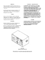
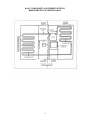
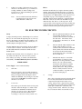
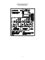
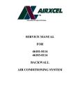
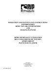
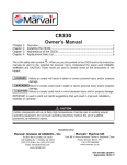
SERVICE MANUAL
FOR
ROOF TOP AIR CONDITIONERS
PREFACE
!WARNING – SHOCK HAZARD!
This service manual is primarily intended for the use of
qualified individuals specially trained and experienced in
the service of this type of equipment and related system
components.
Installation and service personnel are required by some
states, counties or cities to be licensed. Persons not
qualified shall not attempt to service this equipment or
interpret this service manual.
SCOPE
This is not a basic refrigeration and air conditioning
manual and does not therefore, cover the principles of
refrigeration or air conditioning. The user of this manual
should have already accomplished a thorough study of
refrigeration and air conditioning.
WARNING
Improper installation may damage equipment, can
create a hazard and will void the warranty.
TO PREVENT THE POSSIBILITY OF SEVERE
PERSONAL INJURY, DEATH OR EQUIPMENT
DAMAGE DUE TO ELECTRICAL SHOCK,
ALWAYS BE SURE THE POWER SUPPLY TO THE
APPLIANCE IS DISCONNECTED BEFORE DOING
ANY WORK ON THE APPLIANCE. THIS CAN
NORMALLY BE ACCOMPLISHED BY
SWITCHING THE BREAKER FOR THE AIR
CONDITIONER TO OFF, DISCONNECTING ALL
EXTERNAL ELECTRICAL CONNECTIONS AND
CORDS, SWITCHING ON-BOARD ELECTRICAL
GENERATORS AND INVERTORS TO OFF, AND
REMOVING THE CABLE FROM EACH POSITIVE
TERMINAL ON ALL STORAGE AND STARTING
BATTERIES.
DANGER
SOME DIAGNOSTIC TESTING MAY BE DONE ON
ENERGIZED CIRCUITS. ELECTRICAL SHOCK
CAN OCCUR IF NOT TESTED PROPERLY.
TESTING TO BE DONE BY QUALIFIED
TECHNICIANS ONLY.
The use of components not tested in combination with
these units will void the warranty, may make the
equipment in violation of state codes, may create a
hazard and may ruin the equipment.
6757A7201
SERVICE TEST DEVICE
This test device is an invaluable aid in quickly diagnosing repairs
to all Airxcel, Inc. roof top air conditioners produced after 1979.
TABLE OF CONTENTS
I.
Basic Components . . . . . . . . . . . . . . . . . . . . . . . . . . . . . . . . . . . . . . . . . . . . . . . .
5
II.
Air Handling . . . . . . . . . . . . . . . . . . . . . . . . . . . . . . . . . . . . . . . . . . . . . . . . . . . .
5
III.
Electrical Power Circuits . . . . . . . . . . . . . . . . . . . . . . . . . . . . . . . . . . . . . . . . . .
6
IV.
Capacitors . . . . . . . . . . . . . . . . . . . . . . . . . . . . . . . . . . . . . . . . . . . . . . . . . . . . . .
7
V.
Meters . . . . . . . . . . . . . . . . . . . . . . . . . . . . . . . . . . . . . . . . . . . . . . . . . . . . . . . . . .
7
VI.
Free Delivery Ceiling Assemblies . . . . . . . . . . . . . . . . . . . . . . . . . . . . . . . . . . . . 8
VII.
Service Problems and Their Possible Solutions. . . . . . . . . . . . . . . . . . . . . . . . . 9
VIII. Typical Wiring Diagrams . . . . . . . . . . . . . . . . . . . . . . . . . . . . . . . . . . . . . . . . . .
3
10
BASIC COMPONENTS AND THEIR FUNCTIONS
REFRIGERATION SYSTEM DIAGRAM
4
I. BASIC COMPONENTS
Compressor
Metering Device
The compressor is called a hermetic compressor which
means that it is completely sealed (welded together). It is,
therefore, not internally field serviceable. Inside the
compressor housing is an electric motor which drives the
compressor.
The refrigerant enters the cap tube from the condenser as a
warm high pressure liquid. As the refrigerant flows
through the small diameter cap tube, the pressure drops
rather rapidly. The liquid temperature is constantly
lowered as it passes through the cap tube. As the
refrigerant leaves the cap tube, it is still mostly liquid;
however, a small portion has changed to a vapor called
flash gas. When the liquid refrigerant passes from the cap
tube to the evaporator, it is at low side pressure and will
therefore vaporize at low temperature as it picks up heat
from the air being conditioned.
Mounted on the outside of the compressor housing is a
two-terminal overload switch. Note: We have a few
models with internal overloads that are non-serviceable.
The switch is connected in series with the common
terminal, so if the switch opens, it will cut the power to the
compressor motor. The switch will open as the result of
either heat or amperage conditions that could be harmful to
the compressor.
Evaporator Coil
The purpose of the finned evaporator coil is to transfer the
heat from the warm and moist indoor air to the cold low
pressure refrigerant.
Condenser Coil
The purpose of the finned condenser coil is to transfer heat
from the high pressure refrigerant to the warm outdoor air.
As the outdoor air passes over the coil, the heat transfer
will cause the air temperature to rise. Thus the condenser
discharge air will be several degrees warmer than the
condenser entering air.
II. AIR HANDLING
disconnect plug to the selector
switch. The red wire from the
motor connects to a red wire in
a wire nut then the red wire
connects through the disconnect
plug to the selector switch.
Fan Motor
The air conditioning unit has one double end shaft fan
motor. On one shaft is mounted a centrifugal or squirrel
cage blower which draws air (return air) out of the
recreational vehicle and blows the conditioned air down
into the recreational vehicle. On the other end is mounted
an axial flow or propeller type fan which circulates
outdoor air through the condenser coil.
* Some models use a squirrel cage on both ends of
the motor.
An important step in installing a replacement fan motor is
to check the direction of rotation before it is installed. On
all models, the condenser fan pulls the air through the coil.
b)
The white wire from the motor
connects to the fan capacitor or
a white wire in a wire nut then
the white wire connects through
the disconnect plug to the
thermostat.
c)
The brown wires from the
motor connect to the fan
capacitor.
Fan Motor Check Procedure
If a fan motor refuses to perform properly, it can be
checked in the following manner:
1.
Be sure the motor leads are connected
properly.
a)
The black wire from the motor connects
to a black wire inside a wire nut then the
black wire connects through the
5
2.
If there is a reading of 0 between any two leads,
the motor is shorted and is no good. If there is a
reading of infinity (no meter reading at all)
between any two leads, the winding is open and
the motor is no good.
Note:
Filters
The filters should always be in place when the system is
running. More important than their purpose of cleaning
the air in the living space is the protection the filters give
the evaporator coil. Without filters, a wet evaporator coil
will quickly stop up so that adequate air cannot pass
through it. Filters must be installed to completely fill the
filter rack so that no air can flow around them or bypass
them and carry dust, lint, etc. to the evaporator. If an
evaporator has not been properly protected by its filter, the
entire unit must be removed from the recreational vehicle
and the coil cleaned with special detergent and water.
A motor with 2 brown leads will have a
0 reading between 1 brown wire and
either the black or white wire.
III. ELECTRIC POWER CIRCUITS
Safety
a)
The wire with black insulation is the hot
wire and there should be 115 volts
(domestic USA) between it and either of
the other wires. All switches, fuses,
circuit breakers, disconnects, etc. should
be in this line.
b)
The wire with the white insulation is the
neutral. There should be 115 volts
(domestic USA) between the neutral and
the hot (black) wire, but there should be
0 volts between the neutral and the
ground (the green wire or the frame of
the air conditioner).
c)
The third wire may be covered with
green insulation or it may be a bare
metal wire. It is the ground wire. There
must be 115 volts (domestic USA)
between this wire and the hot (black)
wire and 0 volts between it and the
neutral (white) wire. The ground wire
must be securely fastened to the air
conditioner cabinet. A ground screw is
provided for this purpose.
Voltage (electrical pressure), whether high or low, will not
hurt you. It is the current through vital parts of your body
that does the damage, and under the right conditions, 115
volts (domestic USA) is plenty to drive a deadly dose of
current (amperes) through your body.
Another imminent danger from electric shocks in addition
to electrocution is reaction. An electrical shock causes
uncontrollable muscular contractions which can cause
further injuries.
Remember that electricity can be very dangerous - but you
can safely work with it. In order to be safe, you must
know what you are doing. You must work deliberately
and carefully. You must think safety before each move.
THINK SAFETY
Power Supply – from Commercial Utility
1)
Wire Size
The power supply to the air conditioner must be
wired through a circuit breaker or time delay fuse.
The power supply must be 20 amperes and 12
AWG wire minimum. Any size larger at any time
may be used and should be used if the length of
the wire is over 32 feet.
2)
3)
Voltage
The voltage (electrical pressure) at the unit should
be 115 volts (domestic USA) and all electrical
components will perform best at the correct
voltage. However, the voltage will vary and the
air conditioning system will perform satisfactorily
within plus or minus 10% of the rated (115)
voltage (domestic USA). Therefore, the voltage
has to be between 103.5 volts and 126.5 volts.
Color Code
The electric power from the electric service panel
should be delivered through a 3 conductor cable
and the Service Technician should check to be
sure the color code is correct. The electrician
probably installed the cable with the colors
according to code, but do not bet your life on it.
6
Power Supply – Generated by on-board motor generator
115 volts (domestic USA) between the black and white
leads, but there will be 0 volts between either lead and
ground.
If the power supply for the recreational vehicle is supplied
by an on-board motor generator, its wiring may be
identical to the commercial power described above.
WARNING
There are, however, some motor generators on which both
the current carrying leads are insulated from the ground.
That is to say; there is no grounded neutral, so there will be
The service technician must keep in mind when checking
to make sure that the power is turned off. Check only
between the hot (black) lead and the neutral (white) lead.
IV. CAPACITORS
Run Capacitor
Start (Potential) Relay
The purpose of the run capacitor is to improve motor
efficiency during running. The run capacitor is always
connected between the start and run or main terminals of
the motor.
The start relay consists of –
1)
Normally closed contacts internally between
terminals #1 and #2 which switch in the start
capacitor in parallel to the run capacitor during
shut down and then switch out the start capacitor
when the motor reaches approximately 75%
normal running speed.
2)
A high voltage coil internally between terminals
#5 and #2 to actuate the contacts.
On some older models, one of the terminals on the run
capacitor will have a red dot (the identified terminal). The
identified terminal should always be connected to the run
or main terminal of the motor and to the neutral line.
Start Capacitor
Most models use a start capacitor and a start relay to give
the compressor high starting torque. The compressor will,
therefore, start against normal pressure difference (head
pressure minus suction pressure) even when shut down for
a short period of time. The start relay will disconnect the
start capacitor when the motor reaches approximately 75%
running speed.
Positive Temperature Coefficient Resistor (Commonly
Known as the PTCR Start Device)
The resistor acts like a potential relay in that it takes the
start capacitor out of the start circuit, but uses resistance of
electrical flow (back EMF from compressor) instead of
opening a set of contacts. The service person should be
careful handling the resistors. They will be hot during
operation (up to 160 degrees F). The air conditioner needs
to be off for 3-5 minutes during cycle time and when
servicing to let the resistor cool down.
V. METERS
together each time it is used because as the dry cell loses
its charge, the meter will get out of calibration.
Ammeter and Its Use
An ammeter is an instrument used for measuring electric
current. This instrument has snap-around jaws that will
allow you to read the current through a wire without
detaching the wire from the system. These meters also
have volt meter and ohm meter attachments so they are an
excellent multi-purpose meter. NO TECHNICIAN
SHOULD EVER ATTEMPT A SERVICE CALL
WITHOUT ONE.
If the probes of an ohm meter are attached to the terminals
of a closed switch, the meter will read 0. This means that
there is virtually no resistance to current flow through the
switch. Now, if the switch is turned off, the contacts will
be open and there will be a very high resistance. In fact,
the resistance is so high it is an infinite number of ohms so
we call this reading infinity.
Ohm Meter and Its Use
Volt Meter and Its Use
An ohm meter is really a resistance meter that is calibrated
in ohms. The ohm meter has its own power source, a
small dry cell, which forces a small amount of current
through a conductor via the meter probes. The meter must
be calibrated to read 0 ohms when the probes are touched
If we attach one volt meter probe to the hot line and the
other probe to the neutral line of a standard circuit, the
meter reading will be the electromotive (electron moving)
force or pressure difference between the two lines.
7
VI. FREE DELIVERY CEILING ASSEMBLIES
Selector Switch – Free Delivery Ceiling Assemblies
the electric heater when the selector switch is in the
heating position. The thermostat is actuated by sensing the
temperature of the return air through the vent where the
bulb is located. Terminal continuity should make and
break if ambient air temperature is between 65 and 90
degrees F.
The selector switch is mounted on the left side of the
interior ceiling assembly. The selector switch allows the
unit to be operated on high to low blower only, or high to
low blower with compressor operation for cooling. On
heating and cooling models, the selector switch can also
switch in the electric heater at low blower operation only.
Heating Element
To check the selector switch, remove wires from the
terminals and rotate the switch to the proper position and
read continuity as follows:
Terminals
L-1-3
L-1
L-2
L-1-4
L-2-4
The heating element is a resistance heater of 1600 watts
(5600 BTUH) capacity and is connected across the line
when the selector switch is set for heating and the
thermostat is calling for heat. The current draw of the
heater (element only) will be 13.3 amperes at 120 volts
(domestic USA models).
Switch Position
Lo Heat
Lo Fan
Hi Fan
Lo Cool
Hi Cool
Limit Switch
The limit switch is a safety switch and is mounted in the
heating element frame. It will open and break the circuit
on temperature rise in case the air flow through the heater
becomes low enough to cause the heater to overheat.
*If you do not wish to remove the wires from each
terminal, disconnect the 9 pin plug from the air
conditioning unit.
Thermostat (Mechanical Rotary)
The thermostat (temperature controller) is mounted on the
right side of the interior ceiling assembly. The thermostat
controls the on-off cycle of the compressor when the
selector switch is in the cooling position. On heating and
cooling models, the thermostat controls the on-off cycle of
8
VII. SERVICE PROBLEMS AND THEIR
POSSIBLE SOLUTIONS
SERVICE PROBLEMS WITH AIR CONDITIONER
AND FREE DELIVERY CEILING ASSEMBLIES
The following list of service problems covers only some of the more common problems which may occur and lists only the
more probable causes. In many instances, it will be necessary to use the wiring diagram in this manual to check out the
electrical circuits step by step, starting at the power source.
POSSIBLE CAUSES
(REFER TO THE INDIVIDUAL COMPONENT
CHECKOUT PROCEDURES)
PROBLEMS
Nothing Runs, No Compressor, No Fan, No Heat
No A/C Voltage, Selector Switch
Fan Runs, No Compressor Operation in the Cooling Mode
Insufficient Voltage to the Unit, Wiring, Thermostat, Start
Capacitor, Run Capacitor, Start Relay, Open Overload,
Selector Switch, Compressor
Heat or Compressor Runs, No Fan Operation
Wiring, Selector Switch, Fan Capacitor, Fan Motor
Fan Runs, No Electric Heat Element
Wiring, Thermostat, Selector Switch, Limit Switch, Outdoor
Thermostat, Heating Element
Air Flow Restrictions, Outdoor Thermostat May Open Due to
Low Ambient Temperature, (Undersized) Too Much Heat
Loss in the Vehicle, Refrigeration System, Very Little or No
Refrigerant Charge, Compressor
Air Flow Restrictions, High Ambient Temperature,
(Undersized) Too Much Heat Gain to the Vehicle, Refrigerant
System, Very Little or No Refrigerant Charge, Compressor.
(IF YOU HAVE NOT BEEN PROPERLY TRAINED IN
REFRIGERATION SEALED SYSTEM REPAIRS, DO
NOT ATTEMPT TO BREAK INTO THE SYSTEM.)
Compressor Runs, Fan Runs, Insufficient Heat
Compressor Runs, Fan Runs, Insufficient Cooling
9
WIRING DIAGRAMS
9330X713, 9330X714 COOL ONLY
CEILING ASSEMBLIES
9330X715, 9330X916 HEAT/COOL CEILING ASSEMBLIES
10
7000 SERIES ROOF MOUNT
AIR CONDITIONERS
11
8000 SERIES ROOF MOUNT
AIR CONDITIONERS
9000 SERIES ROOF MOUNT
AIR CONDITIONER
12
Airxcel, Inc.
RV Products Division
P.O. Box 4020
Wichita, KS 67204
1976G141 (12-11)
13