1
OWNER'S
MANUAL
MODEL NO.
917.254791
CRRFTSMRN
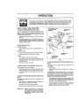
Caution;
Read and follow
all Safety Rules
and Instructions
Before Operating
This Equipment
12.5 HP OHV
ELECTRIC START
38" MOWER
5 SPEED TRANSAXLE
LAWN TRACTOR
• Assembly
• Operation
• Maintenance
• Service and Adjustment
• l_.epair Parts
Sears, Roebuck and Co., Chicago, IL 60684 U.S.A.
SAFETY RULES
PLUGTO PREVENTACCIDENTALSTARTINGWHENSETTING_UP,TRANSPORTING,ADJUSTINGOR MAKING
CAUTION:ALWAYSDISCONNECTSPARKPLUGWIREAND PLAOEWIREWHEREIT CANNOTCONTACTSPARK
REPAIRS_
A
IMPORTANT
SAFETYSTANDARDSREQUIREOPERATORPRF..SE
NCECeNTRe LSTO MINIMIZETHERISKOFINJURY YOURUNil" ISEQUIPPEDWITHSUCH
CONTROLS. DONOT ATTEMPTTO DEFEATTHE FUNCTIONOF TRE OPERATORPRE,SENCECONTROLSUNDERANY CIRCUMSTANCES_
TRAINING:
Know the controlsand how to stop quickly. Read thisowner's
manual and instructionsfurnishedwith attachments:
Do not allow children to Operate the machine, Do net e_low
edWlsto operate it Witheutpropertnslr00tion.,
De not:carry passengers, Do nat mow when cht!dren and
others al:e b:mund., :,::
' ,. '
Do noi;_ttem_t to ope[aie your vehicle or nlowsrwhen not In
the driver's seat. _ :;
' "i';: :! ";.' - _ "." !
Always"gat or_OrOffybur:V_htCe f_'omthb Ope_ai6/'s tafthand _
sldeo
: ; ,
"_,," ,:;! '::' _:"
';_, _' '.
The vehlble Bnd aetBchments s_oii],_l:b_ stopped and In;
spooled for damage after strfklng _.foielgn objecl, end the '
carnage should be repaired beloreiieslarting and operat ng
the equipment.
< _ ;_'
i",
PREPARATION:
*
"_
,
•
•
:_!,__"
Always wear substantial footwear. Do not wear loose fitting
clo_hJng
that could get caught in moving parts,
Clear the work area of objects (wire, rocks, etc ) which might
be pickedup and thrown_
Disengage all attachment clutchesbefore attempting to start
the engine.
Handle gasolinewith car_-'ll Is highly flammable.
Use approved gasolin_containers.,
Never remove thefu_el:eapof tF_e'fdelta_nk
or edd gasoline
to a running or hot b_igidedr an efigi_e that has not been
allowed to coolfoi _:eveta "i_tetJtes
after running,Never
flit tank Indoors Alway_ clead up spilled gasoline.Open doors If lhe engine Is run In the garage - exhaust
fumes ere dangerous, De not run the engine Indoors
Do not operate the mower without the entire grass catehei',
on mowers so equipped or the deflectorshield _nplace:
owner's
'
0 P ERATION;
*"
Keep your eyes and mind on your vehicle mower and the
area being cut. De not let other tntsres_ distraCt you.
Disengage power to ettachrae_s aniJs_o'pthe engine before
leaving the operator's position_
....
i ',,
Disengage power to mower,stop the engine, and d_sconnect
spa_kplug wite(s)from spark plug(s)before cleaning, making an adjustment, or repair, Be careful to avoidtouchinghot
muffler or engine compononts_
Disengage powerto attachments when transporting or not In
,
,
Take all poestble precautions when leaving the vehicle unattended D{sangage the power take-off, lower the attach_
manta, shift inlo neulret, set the parking brake, stop the
engine, and remove the key.
Do not stop or staff suddenly when golng uphill or downhill,
Mow up end down the face of slopes (net greater than "_5"},
never across the face.
Reduce speed on slopes and make t0ms gradually top_event
tipping or loss of control. Exercise extreme caution when
changing direction on slopes.
While goingup or down slopes piece gearshift control lever
in I st gear position to negotiate the slope without stopping. ',
I
,
BECOME
ALERTII!
AND STORAGE
Keep the vehicle end attachmentstn good operating condition, and keep safety devicestn pface and working.
Keep all nuts, bolL%and screws tight to be sure the equipment is in sate workingcondition.
Never storethe equipment with gasot{nein the tank _nsidea
bulldtng where fumes may reach an open flame or spark
Allow the engine to cool before stodng In any enclosure
Toreduce fire hazard keep the englne free of grassjeaves,
or excessve grease, Do not clean product whileengine is
running,
De not operate without a muftier, or tamper with exhaust
system Damaged mufflers or spark anestare could create a
fire hazard inspect periodicallyand replace if necessary.
Under normal usage the grass catcher bag mated_J ts
subject to deterioration and wear, tt should be checked
frequenttyfor bag replacement Replacement bags should
be checked to ensdre compliance with the orfgfnal
manufacturer's recommendationsor spec_calJens.
LOOK FOR THIS SYMBOL TO POINT OUT IMPORTANT
tT MEANS-ATTENTIONH
manual_
Watch out for trafficwhen crossing or near roadways
When using any attachments, never direct discharge of
material toward bystanders nor allow anyone near the vehicle whilelh operation,
Except foradjustments,de not operate engine if air cleaner
d.r,cover directly over carburetor air intake is remeved_
Removal of suchpart could create a fire hazard.
Do nbt change the engine governor settings or overspeed
the engine; severe damage or injury may result.,
When using the vehicle wilh mower, proceed as follows:
s_ow oniy in daylight or Ingood artftictal light.
_ut _e engine off when unelogglng chule.
Check the blade mounting bolls for proper tightnessat
frequent tntewats.
Disengage power to mower before backing up, Do not mow
In reverse unless absolutelynecessary and then onlyafter
careful observation of the enUrearea behindthe' mower
MAINTENANCE
USe_
,
Never mow inwet or stippery grass,when tractionis unsure,
or at a speed which could cause a skid.
Stay alert for holes in the terrain and other hidden h_Lzerdso
Keep away fromdrop.offs.
De not ddve too dose to creeks, ditches, and public high.
ways.
Exercisespectei carewhen mowingaround fixedobjectsin
order to preventthe blades from strikingmere. Never deliberately runvehtde or mower Intoor over any foreign objects.
Never shift gears un'_lvehicle comes to a stop
Never place hands or feet under the mower, in discharge
chute or near any moving parts while vehtcie or mower is
runnng Always keep clear of discharge chute
Use cam when pulling loads or using heavy equ_pmenL
Use only approved drewbar hitch points.
Umll feeds te those you can safely control
Do not turn sharptyoUse care when backing
Use counterweight or wheel weights when suggestedin
sAFETY
YOURSAFETY
PRECAUTIONS,
IS INVOLVED.
CONGRATULATIONS
on your
Tractor.
tt has been designed,
purchase
engineered
of a Sears
ahd manu-
factured to give you the best possible dependabll!ty
performance.
and
Shoutd you experience any problem you cannot easily
remedy, please contact your nearest
Sears Service
Department.
We have competent
welt-trained technicians and the proper tools to service or repair this un t,
Please read and retain this manual. The instructions will
enabte you to assemble and maintain your unit properly.
Always observe the "SAFETY RULES"..
MODEL
NUMBER
PRODUCT
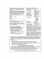
SPECIFICATIONS
HORSEPOWER;
t2,5
.__
GASOLINE CAPACITY:
5 QUARTS
UNLEADED REGULAR
OIL: (2,0 PINTS
CAPACITY)
SAE 30 (or t0W-30)
WINTER: SAE 5W.30
,
"-SPAR_
GAP: (,030 INCHES)
,,
, ,,
CHAMPION RL860
STD360952
VALVE CLEARANCE:
[NTAKE:
EXHAUST:
.002 IN
004 IN.
917254791
GROUND SPEED:
SERIAL
NUMBER
FORWARD'.
tst- t,10 MPH
2nd..2.00MPH
3_d-3 O0MPH
4th *4 _oMPH
5Ih -5 CoMPH
t,50 MPH
DATEOFPURCHASE
THE MODEL AN D SERIAL N UMBERS WILL BE FOUN D
ON A PLATE UNDER THE SEAT
YOU SHOULD RECORD BOTH SERIAL NUMBER AND
DATE OF PURCHASE AND KEEP IN A SAFE PLACE
FOR FUTURE REFERENCE.
MAINTENANCE
AGREEMENT
A Sears Malntenan(_e Agreement Isavailable on this prod_
uct. Conlact your nearest Sears store for details,
CUSTOMER
RESPONSIBILITIES
•
Read and observe the safety rules.
•
Follow a regutar schedule in maintaining, caring for and
using your unit.
Fotlow the instructions
under "Malntenance"
end
"Storage" sections of this owner's manual
REVERSE:
TIRE PRESSURE:
FRONT: 14 PSI
REAR: t0 PSI
CHARGING SYSTEM;
3 AMPS @ 3600 RPM
BLADE BOLT TORQUE;
30-35 FT_L.BS.
WARNtNG: This unit is equipped wilh an Internal combus_
tlon engine and should not be used on or near any unimproved forest-covered,
brush-coveted
or grass-covered
Iand unless the engine's exhaust system is equipped with
a spark arrester meeting applicable local or state laws (if
any) If a spark arrestor Is used, It should be maintained tn
effecltve working order by the operator.
in Ihe state of California the above is required by law
(Section 4442 of the California Public Resources Code)
Other states may have sire!tar laws Federal laws apply on
federal lands A spark arrestor for the muffler Is available
through your nearest Sears Authorized Service Center
(See REPAIR PARTS section of this manual)
1, ,,,u ,H
,
11
, ,.
LIMITED TWO YEAR WARRANTY ON ELECTRIC START RIDING EQUIPMENT
For two years from date of purchase, when this ffding equipment is maintained, lubricated, and tuned up according to the
operating and maintenance instructionsin the owner's manual, Sears wfl! repair free of charge any defect in material or
workmanship
This Warranty does not cover;
Tire replacement or repair caused by puncturesfrom outside objects (sUch as nails, theme, stumps, or glass).
Expendable items which become worn dudng ne_rna}use, such as blades, spark plug, e}r cleanersand balls,
Repairs necessary because el operator abuse or negligence, includingbent crankshafts and the failure le matntaln the
equipment according to the instrucllons cenlained In the owner's manual
Riding equipment used for commercial or rentaJpurposes,
FULL 90 DAY WARRANTY
ON BATTERY
For g0 days fromdate ofpurchase, if any battery Inoludedwith this riding equipmentproves delective in material or workmanship
and our testing determines the battery will not held a charge, Sears will reptace the bai,lery at ne charge
WARRANT'( SERVICE iS AVAILABLE BY CONTACTING THE NEAREST SEARS SERVICE CENTER/DEPARTMENT IN THE
UNITED STATES. THIS WARRANTY APPUES ONLY WHILE THIS PRODUCT IS IN USE IN THE UNITED STATES.
This Warranty gives you specificlegal rights, and you may also have other rightswhich v_ry from stats to slate.
SEARS, ROEBUCK
AND CO., D/731CR-W
SEARS TOWER,
CHICAGO,
IL 60684
,,
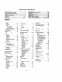
TABLE
OF CONTENTS
SAFETY RULES ........... ...............................
;........ ;........ 2
PRODUCT SPECIFICATIONS
........................................
3
CUSTOMER RESPONSIBILITIES
................................. 3
WARRANTY ...............................................................
_........3
TABLE OF CONTENTS ..................................................
4
INDEX ..............................................................................
4
ASSEMBLY ........................................
;....................... 7-9
OPERATION ............................................................
10-13
MAINTENANCE ........................................................
14-17
SERVICE AND ADJUSTMENTS
............................
18-24
STORAGE ....................................................................
25
TROUBLESHOOTING
............................................
26-27
SCHEMATIC ................................................................
29
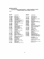
REPAIR PARTS - TRACTOR .................................
30-43
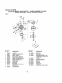
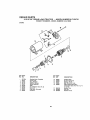
REPAIR PARTS- ENGINE .....................................
44-49
PARTS ORDERING/SERVICE
................... BACK PAGE
INDEX
A
Adjustments,*
Brake .......................................
21
Carburetor...L ............................. 24
Mower
P
Parking Brake
Parts Bag .................................
6
Parts, ReplacemenL/Repalr......
80.49
ProductSpecifications ..............
3
R
..................
16
17
_',
3
"
10,1
t
- o .............
19
12
Side-To..Side ......................... 1B
25
Throttle Control Cable
24
23
Repair Paris .......................
30-50
Ttansaxle Shifter Unkage ........ 21
S
Air Fliter, Engine .......................
16
Hood RemovafllnstallaUon .............
23
Safety Rules ...........................
2
Air Screen, Engine.................
I6
L
Seat ..........................................
..8
Assembly ........................
7-9
LevelingMower Deck ..: ..........
18-19
Service and Adjustments .......... 18-24
B
Lubrication:
Carburetor .................
24
Battery:
Fuse
23
Chart .......................
14
Chmgtng........................
8
M
Hood Removaltlnstallalton .... ff23
Cleaning .............................
16
Motion Drive Belt
Malhtenance ......................
14.17
tnslaltation ...............................
g
Removal/Replacement ....... 21
Air Filter, .......................
16
Levels ...............................
B,15
Mower Blade Drive Belt
A_rScreen, Engine ................... 16
Preparation ............ ., ............. 8
Removal/Replacement .......... 20
Battery ....................................
15
Starting with Weak Battery ...... 22
Mower Adjuelment
Blade
Storage ..................
25
Frontto-Back ..................
19
Cooling Fins, Engine ...............
17
Terminals ....................
16
Side-to*Side ......................... 18
Engine
011
.....................................
16
Belt:
Mower Removal .....................
18
Fuel Filter ;...........................
17
Molton Drive
Tire Care ........................
8,15,22
Lubribatlon
Chart ........................ 14
Removal/Replacement
,,,21
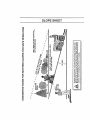
Slope Guide Sheet ....................
51
Schematic .........................
2g
Mower Blade Ddve
Spark Plugs ...............................
17
Spark
Plugs
......................
17
Removal/Replacement .....20
Specifications.......................
3
Tire Care ....................
BJ5,22
Btade:
Tranaaxle_.
........................
21
Startingthe Engine
13
Sharpening ......... ...............
14
Steering Wheel .......................
7,22
Mower:.
Replacement .....................
14
Stopping the Tractor ...............
1t
Adjustment, Frbnt-tmBack .... 19
Brake Adjustment ............................. 21
, Storage ................................
25
Adjustment,
Stde-to-S!de......
18
C
Blade Sharpening....................... {4
T
Carburetor Adjustment ......._.......
24
Throttle ControlCable
Blade Replacement. .................... 14
Controls, Tractor
10
Cuttlng Level .......................
11
Adjustment .............................
24
Cutllng Level, Mower ....................
11
Installation ...................................
18
33ms..............................................
8,15,22
E
Operation
.............................
12
Trouble ShootingChart
........
27-28
Electrlcah
Removal ..........................
1B
Transaxle:
_nterlocks and Relays
, 23
Mowing Tips . .............................
t3
Wlring Schematic ...........
;29
Repair Parts.. .............
42.43
Muffler ....................... . ..................... 17
Wiring Diagram .....................
;_0
W
Spark Arreslar ..,
..............
3,34
Engine:
Warranty..............................
3
O"
AIr Filter ...............
16
Wiring Diagram ........................
30
Oil:
Air Screen ........................
16
Wiring Schematic ..........................
29
ColdWeather Conditions ...... 12,16
Cool]ng Fins,Engine .............. 17
Engine ............................
16
OII Change ..................
I8
Storage .......... :..................
25
O11Level ..............
I2,t6
Operation .......................
10-13
OilType ...........................
16
Operating Mov_er ....................
12
Praparaiton .............................
12
Options:
Repair Parts ................
30.49
Spark Arrestor ...................
3_34
Starting ....................
13
Storage .......................
25
...............
Frot_-To-rBack
F
Filter;
Air CIeaner, ,., ................
Fuel ..................
;.......
Fuel:
Type ................... _................
Storage ......................
Fuse ................
_..............
:
H
........................................
....................................
14
.....
..................
........................
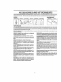
ACCESSORIES AND ATTACHMENTS
,,, i, ,,
,,
,,i,H ,, ....................
These accessories and attachments were available when the unit was purchased They are also available at most Sears ral_li outlets,
catalogand service cents rs M_stSearsst_rascan_rder_heseitemsf_ry_uwh_ny_upt_vld_themodeinumb____yo_rtract_r
ENGINE
SPARKPLUG
MAINTENANCE
MUFFLER
AIR FTLTER
GAS CAN
[ ENGINEOIL
STABILIZER
BLADES
BELTS
PERFORMANCE
Sears offem a w_devarlety of attachments that ftt your vehicle Many of these are listed belowwith bdef explanations of how they can help
you This iist was currentat the timeof publication; however,It may changeIn future years - mars attachments may be added, changesmay
be made In these attachments, or some may notongarbe eva|tableorfityour mode! Contsctyour nearest Sears store for the accessories
and attachments that ere available for your unlL
Most of these attachments do not require additional hitches ar conversionkits (those that do are thdIcated) and are designed for easy
at_ch[ng and de|achthg.
PERMANEX BAGGER lets you collect grass c_tpptngsand
leaves for a healthier, nearer {0eking lawn. Two Permanex
containersherd 30-go!IonpiasUcbags,
LAWN SWEEPERS let you coltsotgrass cflppthgsand ]eaves
LAWN VACS for powerfulcollection of heavy grass clippings and
tsavas. Wand attachment to pick up debds in hard-to-reach
places
CARTS make hauling easy Variety of sizes available
ROLLER for smoother lawn surface. 36-thch wide, 18 Inch
diameterwater-tight drum holds up to3B01be.of weight. Rounded
edges prevent harm to turf Adjustabte scraper automaUcally
cleans drum
SPREADER/SEEDERS make seeding, fertl!lzthg, end weed klilfng easy. Broadcast spreaders are also asafui tot granular deicersand sand
CORING AERATOR takes email plugs out of _oll to allow robinlure and nutrients |o reach grass roots 36-thch swath 24
hardened steel codng tips. 150 Ib cepasItyweight tray
AERATOR promotes deep root growth for a heaithy lawn. Topared 2,5" sisal spikes mounted on '_O-th.diameter d{scs puncture holes in soil at close inferrersto tst moisture soak In. Steel
weight tray for Increased penetration.
DE'THATCHER toosansso_{and flipsthatch and matted leaves to
lawn surface fat easy pickup Twenty springline teeth. Usefulto
prepare bare areas for seeding. Available for front or rear
mounting
SPRAYERS use 12-volt DO electric motet that connects to the
traclor battery or other 12-vett source. Incfudes booms for
automatic spraying when pulling, end hand held wand for spot
spraying, Wand has adjustable spray pattern. For applying
herbicides, Insecticides,fungicides, and liquid fertilizers
SNOW BLADE for snowremoval only. 14-inch high,42-Inch wide
blade clears38 tnch path when angled leftor right Ratsas, lower_
with side lever. Adjusfable skids; replaceable,reversiblescraper
bat (Use with Urechatha,wheel weights,or rear drawbar weight)
SNOW'rHROWER has 404nch swath. Drum-type augerhandtes
powdery and weVheavy snow Mounts easIty with simple ptn
arrangement., Discharge chuteadiusts from tractorseat. 6-thch
dlametetspoutdtschargessnow lOtoSOfeet
Uft controlled at
tractor seat. (Use with chains, wheel weights, or rear drawbar
weight )
TIRE CHAINS are heavy duty; closely spaced extraqarge cross
links give smooth ride, outstanding traction
WHEEL WEIGHTS for rear wheels provide needed tractionfor
snow removalor dozing heavy materials. In patm. (30 [bs.each )
TRACTOR CAB has heavy duty vthyl fabric over tubular stset
frame, ABS plastictop; steerplastic w_ndshleldoffers360 degree
Vtstbltl_ Hinged metal doors with catch, Keeps operatorwarm
and dry Remove vinyl and windshieldsfor use as sun protector
In summer.
Optional accessories for traolor cab: lintsdi'Iamperod solid
safety glass windshieldwith hand operated Wiper;12-vol! amber
caugonlight tar mounting on cab top.
TRACTOR COVER protects tractor from weather. Made of
Evolution3 fabric (water-repellent, extremely breathable, ltght
walght, soft, non-abrasive, pIfab{ein all temperatures, durable,
stathltsar[puncttJre resistant, wilt not shdnk or stretch)
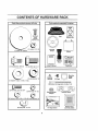
CONTENTS OF HARDWARE PACK
,
L
Parts
=
J, ii
Bag contents
i
shown
Parts packed separately In carton
full size
,,=u,,i
©
= =, i
Seat
(2) Sheet
Metal
Screws
#10-16 x 1/2
Battery
acid
Steering
Wheel
I
Steering
Boot
Owner's
(I) Shoulder Bolt 5/16-18
Manual
%
_
(2) Battery
Carriage
Steering
Bushing
(1) Washer
Parts Bag
(1) Hex Bolt I/2-13 x I
(2) Keys
_
Steer,og
Wh0al
Insert
17/32 x 1-3/16 x 12 Ga,
(2) Hex Baits
Bolts
1/4-20
X 7-I/2
1/4 - 20 x 3/4
Steering Wheel
Adapter
®
Terminal Guard
(2) Hex Nuts 1/4 - 20
12) Washers
9/32 x 5/8 x 16 Ga. (2) Lock Washers
1
1,!4,
I
i
,
121Wing Nuts
I/4 ° 20
15= Slope Sheet
i
i
1
Battery Caps
and Instructions
ASSEMBLY
TOOLS
REQUIRED
FOR ASSEMBLY
INSERT
A socket wrench set wi[f make assembly easier, Standard
wrench sizes are listed°
(I) 5/16" wrench
(I)
(2) 7/16" wrenches
Tire pressure gaugD
3f4" wrench
(1) t/2" wrench
Screwdriver
(I) 9/16 = wrench
Utility knife
When right or left hand Is mentioned in this manual, it
means when you are in the operating position (seated
behind the steering wheei).
TO REMOVE UNIT
UNPACK CARTON
FROM
CARTON
Remove all accessible loose parts and parts cartons
from carton (See page 6)
,
Cut along dotted lines on the carton, from top to
bottom, alt four comers of carton and lay panels fiat.
Check for any additional
remove
loose parts or cations and
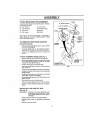
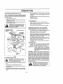
ATTACH STEERING WHEEL (See Fig, 1)
Slide the sleeting bush{ng over the steering
shaft.
Raise steering shaft forward until screw holes in dash
tine up with steering bushtng, install two (2) sheet
metal screws and tighten securely,
Posii]on steering boot over steertng shaft
Ptace tabs af steering boot over slots in dash and push
down to secure.
Slide steering wheel adapter onto upper steering shaft.
Position front wheels of the tractor so lhey are pointing
straight forward.
,
Position steering wheel so cross bars are horizontal
(left to right) and slide onto adapter,
Assemble large flatwasher
tighten securely
and 1/2-20 hex [ocknut and
Snap insert into center of steering wheel
Remove protective plastic from tractor hoed, and grill
Remove banding
tractor
holding discharge guard up against
BEFORE ROLLING UNIT OFF SKID
(See Fig. 6)
IMPORTANT:
,
CHECK
FOR AND REMOVE
ANY
STAPLES IN SKID THAT MAY PUNC.
TURE TIRES WHERE UNiT iS TO ROLL
OFF SKID.
Raise attachment Itft lever to its hlghBsl position,
Release parking brake by depressing
pedal
Roll unit backwards off skid
clutch/brake
STEERING SHAFT
=SHIPPING
OSITION)
STEERING SHAFT
(ASSEMBLY POSITION)
FIG_1
ASSEMBLY
HOW TO SET UP YOUR
TRACTOR
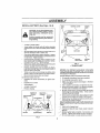
INSTALL SEAT (See Fig. 3)
Adjust seat before tightening
PREPARE BATTERY (See Fig. 2)
.
_i_l
CAUTION: Wear eye and face shield.
Place seat on seat pan and assemble shoulder bolt
Assembte adjustment bolt, lock washer, and flstwasher
loosely, Do not tighten
Tighten shoulder
Do
not smoke.
Fumes
from
charged
accidentally
In contact
with
battery
actd'
battery acid are explosive
Slide seat uoti_ a comfortable position is reachedwhlch
allows you to press dutch/brake pedal all the way down
(See Fig. 6).
Get off seat without moving its adjusted position
Raise seat end ttghten adjustment
Your unit has a battery charging system which is sufficient
for normal use. However, periodic charging of the battery
with an automotive charger wilI extend its I_fe
SEATPAN
Flit battery with acid. Fill each cell until it reaches the
bottom of the vent wells. Do not overfill
SHOULDER
Allow battery to stand and settle for at _east thldy
minutes. After standing, check the leve| of acid
ff
below the vent wells, add more acid until the correct
level _sreached.
BOLT
While battery is standing (after adding acid) and later, while
battery is being charged, continue with assembly of unit
BOLT
NOTE" To n_axlmize the ltfe of your battery, it is necessary
that the battery be charged before use, Use a 12 volt battery
charger. Charge battery at a rate of 6 amperes for 1 hour.
Observe all safety precautions required for battery charging. Faiture to charge battery can result in a shortened
battery life.
FIG. 3
CHECK
CHECK
Dispose of excess battery acid. Neutralize acid for
disposal by adding it to four inches of water in a five
gallon plastic container. Stir with a wooden or plastic
paddle while adding baking soda until the addition of
more soda causes no more foaming.
CHECK
BELTS
FIG. 2
FOR
PROPER
POSITION
OF ALL
VENTCAP
CHECK BRAKE SYSTEM
WELL
After you learn how to operate your tractor, check to see
that the brake is properly adiueted
See TO ADJUST
BRAKE" In the Service and Adjuslments section of this
manual
_/eAI-fERY
_1I__
LEVELNESS
See the figures that are shownfor replacing motion and
mower blade drive belts in the Service and Adjustments
section of this manual. Verify that the belts are routed
correctly.
on how to install bsltery.
J/VENT
_ II B
DECK
For best cuttingresults,mower housing should be properly
leveled- See "TO LEVEL MOWER HOUSING" tn the
Service and Adjustments section of this manual,
Check battery case for leakage to make sure that no
damage has occurred tn handling,
/
PRESSURE
Reduce ttre pressure to PSI shown tn "PRODUCT
SPECIFICATIONS"
on page 3 of this manual.
Instal{ lhe vent caps to cover the vent wells, Wash the
top of the battery with water to remove any acid, then
wtpe dry
CUTAWAYVIEW
TIRE
The tires on your unit were over_nfIaled at the taclory for
shipping purposes
Correct tire pressure is important for
best cutting performance_
Check the acid level after the battery is charged, tf the
acid has fallen below the correct level, add distilled or
iron free water,
I
boil securely,
SEAT
See instructions packed with vent caps in parts bag
Follow instructions
bolt securely.
Lower seat into operating position and sit on seat.
,
9
bolt
wash hands or clothing immedlatefy If
Read the Instructions Included with the
batteryvent caps. Atways wear gloves,
clothing and goggles to protect your
hands, skin and eyes,
*
adjustment
Remove cardboard packing on seat pan.
_1 B,f" CELL
AClO
8
ASSEMBLY
INSTALL
BATTERY
(See Figs, 4 & 5)
WING
NUT
TERMINAL GUARD
ACCESS
DOOR
CAUTION: Do not short battery terminals. Before Installing battery, remove
metal bracelets, wristwatoh bends_
rings, etc0
Positive terminal must be connected
first to prevent sparking from accidental grounding.
,
Lift seat to raised position.
Lower battery into fender wslI with battery terminals
toward front of unit Make sure battery rests in battery
tray
Be sure battery drain tube has not come loose and is
securely attached to drain in battery tray
First connect RED battery cable to posilive (+) flaltery
terminal with hex boIt, flat washer, lockwasherand hex
nut as shown Tighten securely
'
KEY
HOLE
Connect BLACK grounding eabte to negative (-) battery terminal with remaining hex boil, fiat washer,
Iockwasher and hex nut Tighten secure{y
,
Slide the two battery bolts through the terminal
and start the wing nuts onto the threads
,."CHECKLIST
BEFORE YOU OPERATE AND ENJOY YOUR NEW
TRAGTOR, WE WfSH TO ASSURE THAT YOU RE CEfVE
THE BEST PERFORMANCE AND SA TI SFA C TION FROM
THIS QUALITY PRODUCT,
PLEASE REVIEW THE FOLLOWING CHECKLIST,
Tighten wing nuts by hand making sure battery bolls
remain in slots of the key holes in the battery support.
Be sure terminal access doors are ctosed.
Use termina{ access doors for:
for secure connections
,
Inspection for corrosion
,
Testing battery
(Io tighten hard-
Jumping (if required)
,
,/
Alf assembly instructi_:,nshave been. completed
v"
No remainEng loose parts in carton.
,/
Battery is properly prepared and charged.
1 hour at 6 stops).
_ '
,/
Seat is adjusted comfortab{y
,/
All tkes are properly inflated. (For shipping purposes,
the tires were over-inflated at the factor).
,,/
Be sure mower deck is proper_y leveled side-to-side/
front-to-rear fo_' best cutting results. (Tires must be
prol::;eriy ir_tlalsd for tee'sling).
Check mower and drive'belts, Be sure they are routed
properly around pulleys and inside air bert keepers.
Periodic charging
POSITivE t*)
POSITIVE(RED)
NEGATIVE( -)
"fERMttIAL
BATTERY
TRAY
FIG, 5
guard
Position terminal guard over the battery as shown,
lower bolts into key holes and slide square shafts of
bolts into slots of key holes.
inspection
ware)
BATTERY
DRAIN TUBE
v"
NEGATIVE
(BLACK)
V'
(Minimum
and tightened securely.
Check wiring. See that all connections
and *ires are propedy clamped
are still secure
WHILE LEARNING HOW TO USE YOUR TRACTOR, PAY
_RA
A TTENTION.T ° THE FOLLO WING IMPORTANT
fTEMS_ _.
:
HEX NUT
LOCKWASHERS
,/
Engir_e ell is a{ proper levet
,/"
Fuel iank is fi{ted'with
fresh, clean, regular un(eaded
BeCome familia(with
eli contiois .their
v"
fdhot[on. Opec'atethem before YoU start the engine
Besure brake system ls tn safe operating cond_tlon
HEXNUT
;_
FIG. 4
location and
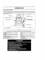
OPERATION
LIGHT SW_CH
CLUTCHiBRAKE
ATTACHM ENT HEIGHT
ADJUSTMENT POSITIONS
PEDAL
IGNITION SW_TCH
PARKING BRAKE LEVER
FIG. 6
Sears Iractors conform to the safety standards
ATTACHMENT
mower blades,
CLUTCH
LEVER - Used to engage the '
tGNI'rION
engine
ATTACHMENT
LIFT LEVER - Used to raise, lower, and
adjust the mower deck or other attachments mounted to
your tractor.
LIFT LEVER PLUNGER - Used to release attachment lift
tever when changing Its position
CLUTCH/BRAKE
PEDAL _ Used for declutchlng
braking the tractor and starling the engine.
of the American
National Standards
institute,,
SWITCH - Used for starting
and stopping
the
GEAR SHIFT LEVER - Setects the speed and direction of
the traeto_
LIGHT SWITCH - Turns the headlights on and off
PARKING BRAKE LEVER - Locks clutch!brake pedal into
the brake position
and
THROTTLE/CHOKE
CONTROL
contre}llng engine speed.
10
o Used for starting and
OPERATION
The operat on of any ractor can result in foreign objects thrown into the Byes which can resull
in severe eye damage_ Afways wear safety glasses or eye shields while operating your tractor
or performing any ad ustments or repairs We recommend Wide Vision Safety Mask for over
the spectacles or standard safety g asses, available at Sears Retail or Catalog Stores.
HOW TO USE YOUR TRACTOR
ATTACHMENT CLUTCH
LEVER "ENGAGED _
POSITION
TO SET PARKING BRAKE (See Fig. 7)
"DISENGAGED"
POSITION
Your unit Is equipped with an operator presence sensing
switch.
When engine ts running, any attempt by the
operator to leave the seat without first setting the parking
brake will shut off the engine
*
Depress clutch/brake
end hold.
pedal Into fuI[ "BRAKE"
GEAR SHIFT
LEVER
position
Place park! ng brake lever In "ENGAGED" position and
retease pressure from dutch/brake pedal Pedat should
remain In BRAKE position Make sure parking brake
will hold vehicle secure
STOPPING (See Ftg, 7)
PARK}NG BRAKE
'ENGAGED"
MOWER BLADES
Move aftachment clutch lever to "DISENGAGED"
sition
po-
GROUND DRIVE Depress dutch/brake
Move gearshift
ENGINE -
pedal into futl "BRAKE" position
lever to "NEUTRAL"
"DISENGAGED"
POSITION
position
CLUTCH/BRAK E
PEDAL "DRIVE"
POSITION
Move throtlIe controJ to "SLOW" posit}on
Turn ignition key to "OFF" posilion and remove key.
Always remove key when leaving vehicle to prevent
unauthorized use.
FIG. 7
TO ADJUST MOWER CUTTING HEIGHT (See
Fig. 6)
Never use choke to stop engine,
The position of the attachment
cutting height,
TO USE THROTTLE
CONTROL (See Fig. 7)
Always operate engine at full throttled
Operating engine at less than full throttlereduces the
battery charging rate and the engine cooling air flow
Full throttle offers the best bagging and mower performance
the
Grasp lift lever
Press plunger with thumb and move lever to desired
positionThe cutting height range is approximately 1ol/4" to 3-3/4".
The heights are measured from the ground to the blade tip
with the engine not running, These heights are approxima{e and may vary depending upon soil condltlons, height
of grass and types of grass being mowed
TO MOVE FORWARD AND BACKWARD
(See
Fig, 6)
The direction and speed of movement Iscontrolled by the
gearshift lever,
Start tractor with clutch/brake pedal depressed and
gear shift lever in "NEUTRAL" position,
Move gear shift lever to desired posiUen
SIowly release clutch/brake pedal to start movement,
The average _awn should be cut approximately 2-!/2
Inches during the cool season and over 3 inches during
hot months For healthier and better looking lawns,
mow often and after moderate growth.
For best cutting performance, grass over 6 Inches In
height should be mowed twice Make the first cut
relatively high; the second to desired height.
IMPORTANT: BRING
TRACTOR TO A COMPLETE
STOP BEFORE SHIFTING OR CHANGING GEARS, FAILURE TO DO SO WILL
SHORTEN THE USFUL LIFE OF YOUR
TRANSAXLE.
lift lever determines
11
OPERATION
TO
OPERATE
MOWER
(See
Fig
8)
Move gearshift lever to ist gear and be sure you have
allowed room for tractor to rotl slightly as you restarf
movemenL
Your unit is equipped with an operator presence sensing
switch Any attempt by the operator to leave the seat w_th
the engine running and the attachment clutch engaged will
shut off the englne.
TO restart movement, slowly release parking brake and
clutch/brake pedal
Make all turns stowly.
Setect desired height of cut
Engage mower by moving attachment
to ENGAGED posttion
TO STOP MOWER - Move attachment
*'DISENGAGED" position:
,
I /_,
clutch lever up
TO TRANSPORT
clutch laver to
Raise attachment lift control to highest position
•
without either the entire grass catcher,
on mowers
so equipped, Dr the disCAUTION;
Do not operate the mower
charge guard in place,
When pushing or towing your unit, be sure gearshift
lever is In "NEUTRAL" position
Do not push or tow unit at more than five (5) MPH
BEFORE STARTING
THE ENGINE
CHECK ENGINE OIL LEVEL (See Fig. 16)
ATTACHMENTCLUTCH
LEVER "DISENGAGED"
POSITION
The engine [n your unit has been shipped, from the
factory, already tilted with summer weight e_l
"x,
ATTACHMENT
LIFT LEVER
HtGH POSITION
Check engine o11with unit on level ground,
Remove oil fill dipstick and wipe dean, replace and
screw cap tight, wait for a few seconds, remove and
read oil level. If necessary, add oil unlit "FULL" mark
an dipstick Is reached
Do not overfill.
For cold weather operation you should change oil for
easier starting (see "OIL VISCOSITY CHART" In the
Maintenance section of this manual).
•
To change engine oli, see the Maintenance
lhts manual,
section in
ADD GASOLINE
Ftlt fuel tank
Use fresh clean regular unleaded
gasoline. (Use of leaded gasoline will increase carbon
and lead oxide deposits and reduce valve life).
IMPORTANT;
WHEN OPERATING
IN TEMPERATURES BELOW 32°F, USE FRESH,
CLEAN WINTER GRADE GASOLINETO
HELP iNSURE GOOD COLD WEATHER
STARTING.
RUNNER
WARNING;
Experience indicales {hal alcohol blended
fuels (called gasollol or using ethane! or methanol ! csn
attract moisture which leads to separation and forma!ion el
acids during storage.
Acidic gas can damage the fuel
system of an engine while in storage
To avoid engine
problems, the fuel system should be emptied before storage of 30 days or longer,
Dra_n the gas tank, start the
engine and let it run untII the fuel lines and carburetor are
empty, Use fresh rue! next season See Storage Instructions for addllional information.
Never use engine or
carburetor cleaner products In the fuel tank or permanent
damage may occur.
DISCHARGE
GUARD
FIG 8
TO OPERATE ON HILLS
I
'
dlt
Z%
hills with slopes greater than 15 _ and
CAUTION,
not any
drivesloper
up or down
do
not drive Do
across
Choose the slowest speed before starting up or down
htlls,
Avoid stopping or changing
If slowing is necessary,
stower position_
I&
speed on hi{is
move throttle control Fever Io
if stopping iS absolutely necessary, push dutch/brake
pedal qutckly to brake position and engage parking
brake,
12
filler neck. Do not overfill
Wipe off any
spilled
oil or FIllto
fuel. Do
not store
spill
or
CAUTION;
bottom
of gas
tank
use gasoline near an open fame.
OPERATION
TO START
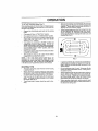
Drive so that clippings are discharged onto the area
that has been cut. Have the cut area to the right of the
machine. This will result in a more even distribution of
clippings and more uniform cutting.
(See Fig. 7)
ENGINE
When starting engine for the first time or if engine has run
out of fuel_ tt wilt lake extra cranking time to move fuel from
the tank to the engine
Depress the clutch/brake
brake
Place gearshift
lever In "NEUTRAL"
Move attachment
When mowing large areas, start by turning to the right
so that clippings will discharge away from shrubs,
fences, driveways, etc. After one or two rounds, mow
In the opposite direction maklng left hand turns until
finished (See Fig, 9),
pedat and set the parking
position.
clutch to "DISENGAGED"
position,
Move throltta control lever to"CHOKE" position for cold
engine start, For warm engine start, move throttle
control to =FAST" position,
•
.
Turn Ignition key clockwise to "START" position and
release key as soon as engine starts, Do not run
starter continuously for more than fifteen seconds per
minute. If engine does not start after severalaltempls,
move throttle control to "FAST' position, wait a few
minutes and try agath
When engine starts, slowly move throttle control iever
to desired running speed
Allow engine to warm up for a few minutes
engaging drive or attachment ciulch
before
NOTE:
If at a high altitude (above 3000 feet or .9I
kilometers) or In cotd temperatures (below 32"F), the
carburetor fuel mixture may need to be adjusted for best
engine performance
See 'TO ADJUST CARBURETOR"
in the Service and Adlustments section of this manuat
FtG. g
tf grass is e×tremety tall it shouJd be mowed twice to
reduce load and possible fire hazard from dr ed c p.
pings. Make first cut relatively high; the second to the
desired height
MOWING TIPS
•
Tire chains cannot be used when the mower housing
is attached to unit,,
Do not mow grass when It Is wet Wet grass will plug
mower and leave undes#abta dumps. Atlow grass to
dry before mowing
Mower should be properly leveled for best mow!,ng
performance, See "TO LEVEL MOWER HOUSING In
the Service and Adtustments section of this manual,,
A_ways operate engine at ful! throttle when mowing to
assure better mowing performance and proper discharge of material, Regulate ground speed by selecting a low enough speed to give the mower cutting
performance as well as the quality of cut deslred.
Use the runner on the right hand side of mower as a
tghuide, The blade cuts approximately an Inch outside
s runner (See Fig.
8)
•
r
When operating attachments, select a ground speed
that will suit the terrain and give best performance of
the attachment being used
The left hand side of mower should be used for trimmlng
'I3
MAINTENANCE
F,LL,=
OAT=S
°
O=eckBrakeOpe=t,oo
iJ ' !"
'V,'
T C=.ckT_rePrese=rer_
for Loose Fasteners
!I/
I
Check
C
SharpenlReplace
li_
T
0
Lubrlca,e Pivot Points
Check Battery Level/Recharge
if
V e
a
Clean Battery and Terminals
V #
Mower Blades
_
=
_
.........
l
V f
Check Engine OII Level
E Cha.0e
E_gine
O,
N
Clean Air Screen
G
Inspect
I
-._.2
V'
V#2i
MUffler/Spark
Attester
C!ean F-ri!!no Co01tng Fins
I
V"
V _'
_
.
.
iv' V,
Replace Spark Plug
Replace Air Filter Paper Cartridge
Replace Fuel Filter
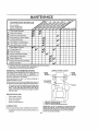
I Changemore oftenwhen operatingunder,aheavyload at in highambienttemperatuteB
2. Serv;cemeteoJtenwhenoperatingindirtyor dustycondt_ens
3 ,,Repl_ceblades moree/tenwhenmowing [nsandysot
"r
GENERAL
RECOMMENDATIONS
LUBRICATION CHART
FRONT
WHEEL
The warranty on this vehicle does not cover ilems that have
been subjected to operator abuse or neglgence,
To
receive full value from the warranty, operator must maintain unit as instructed in this manual
Some adjustments will need to be made pertodlcaly
properly maintain your unl
_
;
*" FRONT
- WHEEL
to
..............
C_
* ATTACHMENT
CLUTCHPIVOT
All ad ustments In the Service and Adjuslments section of
this manua[ shou d be checked at least once each season
Once a year you should replace the spark plug, clean
or replace air filter, and check blades and belts for
wear. A new spark ptug and clean air filer assure
proper air-fue! mixture and help your engine run better
andlast longer.
BEFORE
EACH
USE
Check engine el level,
Check brake operation,
Check tire pressure,
Check for loose fasteners
"
**
LUBRICATION
Keep unit wei lubricated
(See "LUBRICATION
SAE 30 OR 10W30 MOTOR OiL API - SF/CC
GENERAL PURPOSEGREASE
REFER TO ENGINE MAINTENANCE SECTION
IMPORTANT. Do not ot or grease Ihe pivot points which have
special nylon bearings. Viscous lubricants wil attract dust and
d_rtthat wit shorten the life of Ihe set-lubrlcatlng bearings, if
you feel they must be lubricated, use onlya dry, powdered
graphite type lubricant sparingl)'
CHART"),
Front wheel bearings should be greased at feast once
a season.
14
MAINTENANCE
TRACTO R
TO SHARPEN
Always observe safety ru_es when performing
tenance,
any maim
BLADE
(See Fig. 11)
Care should be taken to keep the blade balanced,
An
unbalanced b_ade will cause excessive vibration and eventual damage io mower and engine_
TIRES
.
Maintain proper err pressure in atl tires (See "PRODUCT SPECIFICATfONS
on page 3 of thts manual).
The blade can be sharpened with a file or on a grinding
wheel Do not attempt to sharpen whtle on the mowaro
BLADE CARE
TO check blade balance, drive a naillnto a beam or wall
Leave about one inch of the straight nail exposed.
Place center hole of blade over the head of the nail. tf
blade is balanced, it should remain In a horizontal
position
If either end of the blade moves downward,
sharpen the heavy end untie the blade _s balanced.
For best results mower blades must be kept sharp. The
blades can be sharpened with a file or on a gdnd_ng wheel.
We suggest they be sharpened or replaced after every 25
hours of mowing
Check blades more often if mowing in
sandy conditions
CENTER
HOLE
Keep tires free of gasol.rne, oi!, or Jnsect control chemicals which can harm rubberAvoid stumps, stones, deep ruts, sharp oblects and
other hazards that may cause tire damage,
Do not attempt to sharpen blades while they are on the
mower
Replace bent or damaged blades.
BLADE REMOVAL (See Fig, 10)
Ralse mower
blades.
to highest position
to allow access to
Remove hex bolt, lockwasher and flat washer securing
blade
install new or resharpened b_ade with trail}ng edge up
towards deck as shown
FIG. 11
Reassemble hex bolt, $ockwasher and flat washer in
exact order as shown.
BATTERY
(See Fig. 12)
Your unit has a battery charging system which Is sufficient
for normal use However, periodic charging of the battery
wi{h an automotive charger will extend it's _ife
Tighten belt securely (30-35 Ft Lbs, torque),
iMPORTANT:
BLADE
BOLT IS GRADE
5 HEAT
TREATED.
Acid solution level in each ba_,tery col{ sheuEd be even
w{th bottoms of ventwetls_ Add only distilled or iron free
water if necessary. Do not overfit!.
CUT AWAY VIEW
FLANGES
BATTERY
TRAILING
LEVEL
UP
FIG. 12
Keep battery and term}rials clean
*A GRADE 5 HEAT TREATED BOLT
CAN BE tOENTtFIED BYTHREELtNES
ON THE BOLT HEAD AS SHOWN AT
LEFT,
Keep battery botts tight,
Keep vent caps tight and smaflvent
Recharge st 6 amperes for 1 hour.
FtG_ 10
15
holes in caps open.
MAINTENANCE
i,,
J ,Ll
TO CLEAN BATTERY AND TERMINALS
After oil has drained completely,
and tighten securely.
-
Corrosion and dirt on the battery and terminals can cause
the battery to "leak" power
Refill engine wlth oil through oil ftll dipstick tube. Pour
slowly. D=onot overfill. For approximate capacity see
Proauct Speciacatlons on page 3 of this manual.
Remove term{hal guard
Disconnect BLACK battery cable first then RED batlery cable and remove battery from tractor.
Wash battery with solulfon of four tablespoons of
baking soda to one gallon ofwater Be carefulnot teget
the soda solution Into the celiso
,
replace olt drain plug
Use gauge on ofi lilt dtpstiok for checking leveL Be sure
dipstick cap Is ttgh!ened securely for accurate reading.
Keep ofl at "FULL line on dipstick,
RECOMMENDED SAE VISCOSITY GRADES
Rinse the battery with plain water and dry.
Clean terminals and battery cable ends with wire brush
until bright
Coat terminals with grease or petroleum jeIly,
Reinslall battery (See "INSTALL BATTERY" tn as,,
sembty section of 1his manual).
o20_
0'=
32°
60'_
80Q
100"
FIG. 13
ENGINE
AIR FILTER (See Fig, 14)
LUBRICATION
Your engine wltl not run properly and may be damaged by
using a dirty air fftter. Replace paper cartridge once a year
or after every 100 hours of operation, more often If used In
very dusty, dirty condltLons.
Remove knobs and cover
Change the oil after the first two hours of operation and
every 25 hours thereafter or at least once a year if the
traclor Is not used for 25 hours tn one year
Check the crankcase ott level before starting the Engine
and after each eight (8) hours of continuous use. Add SAE
30W motor oil or equivalent,
Tighten ott lilt cap/dipstick
securely each ttme you check the oil level SAE 5W-30
motor oi! may be used to make starting easier in areas
where temperature ts consislenfty 32" F or lower
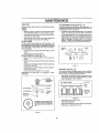
TO CHANGE ENGINE OIL (See Figs 13 & 14)
.
Replace cartridge
Reassemble
NOTE:
and tighten securely
Do not attempt to clean or oi! the paper cartridge.
AIR SCREEN (See Fig. 14)
The engine air screen must be kept #ee of dirt and chaffto
prevent engine damage from overheating. Clean with a
wire brush or compressed air to remove dirt and stubborn
dried gum fibers,
Determine temperature range expected before oil change.
All oil must meet API service classification SD, SE or SF.
Be sure vehicle is on level surface
Oit wt{l drain more |reely when warm
Catch oil in a su[tab!e conlalner
AIR
Remove oil f{]] dipstick
Be careful not to ar!ow dlrt to
enter the engine when changing o1_
ENGINE O1L FILLER
CAP AND DIPSTICK
COVER
Remove drain plug
AIR
BODY
"OIL DRAIN PLUG
FIG. 14
16
MAINTENANCE
i m,nH,
i
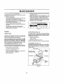
MUFFLER
ENGINE COOLING FINS (See Fig. 15)
Inspect and replace corroded muffler end spark arrestor(if
equipped) as tt couldcreate a f_rehazardand/or damage
Remove any dust, dirt or oll from engine cooling flns Io
prevent engine damage from overheating
Hood and
engine blower housing must be removed to ctean engine
coo_ing fins
SPARK
Remove hood (see "TO REMOVE HOOD" in the Service and Adjustments section of this manual).
•
Remove screws securing air cleaner body and remove (Cover carburetor opening to prevent entry of
dirt)
,
Remove ell fill dipstick and cover opening to prevent
entry of dirt
•
Use compressed air or stiff bristle brush to thoroughly
c_ean engine cooling fins.
Wlth engine
sections
cool,
remove filter and plug fuel line
Place new fuel filter in position in fuel line
reverse above procedure.
Be certain carburetor
are in place
the beginning of each mowing
hours of use, whichever comes
gap setting ts shown in "PRODon page 3 of this manual
1N-LINE
FUEL FILTER
(See Fig, 16)
Fuel flltershould be replaced once each season If fuelfilter
becomes clogged, obstrucling fuel flow to carburetor, replacement is required
Remove screws from blower housing and llft housing
off engine
To reassemble,
PLUGS
Repface spark plugs at
season or after every f00
first. Spark p_ug type and
UCT SPECIFfCAT}ONS"
•
tube, breather tube and gaskets
Be sure there are no fuel line Ieaks and clamps ere
properly positioned
Immediately
wipe up any spilled gasoline,
FUEL FILTER
GASKETS
COOLING FINS \\
CYLINDER
TUBE
\
FIG, t6
CLEANING
CARBURETOR
TUBE
Clean engine, battery,
matler.
SPARK
PLUG
.
Keep finis bed surfaces and wheels free of all gasoline,
oil, etc
Protect painted
JFFLER
seat, finish, etc of oil foreign
sudaces wtfh automotive
type wax,
We do not recommend using a garden hose to clean your
unit unless the electrical system, muffler, air fliter and
carburetor are covered to keep water out Water in engine
can result in a shortened engine _ife
FIG. 15
17
SERVICE AND ADJUSTMENTS
CAUTION;
&
BEFORE PERFORMING
Depress clutch/brake
ANY SERVICE OR ADJUSTMENTS;
pedal fully and set parking braker
Place gearshift lever in "NEUTRAL" position.
Place attachment
clutch in "DISENGAGED"
position,
,
Turn ignition key "OFF" and remove key,
Make sure the blades and all moving parts have completely stopped.
Disconnect spark plug wire from spark plug and place wire where it cannot coma in contact with
plug.
TRACTOR
TO
REMOVE
MOWER
TO INSTALL MOWER (See Fig, 17)
(See Fig, 17)
Raise attachment
Mower will be easier to remove from the right side of unit.
lnstatlparallel link to front axle and mower with hinge
pinE. Secure hinge pins with retainer springs.
Remove retainer spring from clutch rod; pull clutch rod
out of clutch lever
tnatallclutch
spring.
Pult retainer springs out of rear suspension trunniens.
Remove rear suspension trunnlens from lift brackets,
parallel link to mower
Raise lift _ever to raise suspension
out from under tracloh
IMPORTANT:
•
arms
Slide mower
Roll belt over engine pulley, Make sure belt ts Inside all
pultey grooves and Inside belt guides
Raise attachment {ift lever to raise mower.
TO LEVEL MOWER HOUSING
fFAN ATTACHMENT OTHER THAN THE
MOWER IS TO BE MOUNTED TO THE
TRACTOR, THE R.H. AND L,H, SUSPENSION ARMS MUST BE REMOVED
FROM TRACTOR
Adjust the mower while traclor is parked on level ground or
driveway.
Make sure tires are properly inflated (See
"PRODUCT SPECIFICATIONS"
on page 3)° If lires are
over or under inflated, you will not properly adjust your
mower.
SIDE-TOoSiDE
CLUTCH
LEVER*-_._
ADJUSTMENT
Raise attachement
RETAINER
CLUTCH ROD
rod in clutch lever and secure with relainer
Lower attachment lift lever to lower suspension arms°
S_ide trunnlons through lift bracket holes and secure
with retainer springs
Pu_t retainer spdngs from front hinge p{ns
Remove hinge pins attaching
and front axle.
lift lever to its highest positlon,
Slid e mower under tractor with discharge guard to right
side of tractor.
Remove mower blade drive belt from engine pulley
only !,See "TO REPLACE MOWER BLADE DRIVE
BELT throughstepremevingbettfromengine
puiley}.
EPRfNG
•
CLUTCH
ROD
(See Figs 18 and 19)
lilt lever to its highest position.
Measure height from bottom of deck curl to ground
level at front corners of mower. Distance "A" should be
the same.
If distance "A" needs to be changed, snap out access
hofe cover on left side of tractor above footrest.
RETAINEF
SPRING
To raise left side of mower, loosen nut "B" and tighten
nut "C"o
TO lower left side of mower, loosen nut "C" and tighten
nut "B",
When distance "A" is equal securely tighten nuts "B"
and "C"
PARALLEL
BRACKET
RETAINER
SPRING
ENGINE
PULLEY
RepEace access hole cover
HING PINS
FIG,r t7
'18
SERVICE AND ADJUSTMENTS
REAR SUSPENSION ARM
LiFT LEVER
(RAISED
POSITION)
BOTTOM
OF CURL
BOTTOM
EOTTO]_,_
2
OF CU RL
OF CURL
REARSUSPENSIONTRUNNION
--
ii
i
LINE
FIG, 20
---
\
GROUNDLINE
FIG, 18
REAR
SUSPENSION
ARM
SIDETOSIDE
ADJUSTMENT
TRUNNION
LIFT BRACKET
FtGo 21
FIG,, 19
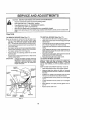
FRONT-TO-BACK ADJUSTMENT(See
Figs 20 and 21) To obtain the best cutting results, the mower housing
should be ad usted so the rear Is approximately 3/4 to 7/8"
higher than the front when the mower s tn its highest
positton_
Check ad ustment on right side of tractor- Measure distance °D' at front and rear flanges of mower housing as
shown
To raise rear of mower, loosen nut "E" on both raar
suspension arms Screw both nuts "F" on both rear
suspension arms an equal number of turns.
When distance "D" is 3/4" to 7/8" higher at rear than
front, retlghten nuts _E"r
Recheck stde-to-sfde
IMPORTANT:
adjustment,
WHEN ADJUSTING
REAR SUSPENSION TRUNNtONS, ALWAYS ADJUST
BOTH EQUALLY
SO MOWER WILL
STAY LEVEL SfDE-TO-StDE,
19
SERVICE AND ADJUSTMENTS
,,.,_.
TO ADJUST
(See Fig. 22)
MOWER
BLADE
DRIVE
tDLER
GUIDE
BELT
BELT
BELT
ENGtNE
LH.
MANDREL
Your tractor has been manufactured with the abi_tly to
readjust the mower blade drive beif to provide you with
longer belt ttfe
With engine off and the lift lever tn the highest position,
move attachment ctutch lever sTowly forward. If the lever
moves significantly forward in the slot before resistance
is felt, adfustmant is necessary
Lower the mower deck for easier access
Remove the bolt, nut and Doshaped washers
rock shaft assembiy
EXTENSION
"SP RiNG
. R,H,
from
Move extension spring from lower to upper end of
slot _n rock shaft assembly and install bolt, nut and
the D-shaped washers (fiat side of washers down)
Tighten boil and nut to secure the D-shaped
ers (llal side down as shown)
NOTE: When Installing
lower end of sloL
TO
REPLACE
(See Figs.
ROCKSHAFT
wash-
a new belt, be sure spring Is in
MOWER
22
BLADE
DRIVE
BELT
23)
and
BRAKE
ROD
The mower blade drive belt may be replaced wtthout
tools Park ihe tractor on level surface. Engage parking
brake. For assistance, there ts a beif Installation guide
decal on the mower housing.
BELT REMOVAL
,
PULLEY
-
Place attachment clutch in "DISENGAGED" position
Move attachment lift lever forward to lower mower to
its lowest position.
NUT
Ro_ beif off engine pulley
Pult belt off both mandrel
FIG. 22
pulleys
Spring bett guide away from idler putfey and pull belt
off idler puIley
Slide belt from under extension
BELT INSTALLATION
BELT
GUIDES
-
Slide belt under extension
PJace belt around
mandrel pulleys
spdng
spring
back side and in groove of both
Spring idler belt guide down and place belt around
rear side of Idler pulley
,
Ro{l belt over engine pultey.
Make sure belt is in al_pulley grooves and inside ell
bett guides
FIG. 23
2O
ENGINE
PULLEY
SERVICE AND ADJUSTMENTS
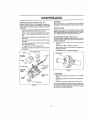
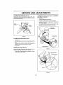
TO ADJUST BRAKE (See Fig. 24)
TRANSAXLE
Your unit is equipped wltll an adjustable brake system
whtch Is mounted on the right side of the transaxie
JUSTMENT
(See Figs, 26 & 27)
The transax[e should be in neutral when the gear shirt lever
ts _n the neutral (lock gate) position, The ad ustmsnt is
preset at the factory; however, if adjustment
s needed,
proceed as re!tows,
If unlt requires more than six (6) feet stoppingdlstance
at
high speed In highest gear, then brake mustbe ad}usted.
Depress clutch/brake pedal and engage parking brake,
Measure dlsLance between
nut "A" on brake rod
brake operating arm and
if distance is other than 1-1/2", disengage parking
brake loosen jam nut and turn nut "A" until distance
becomes 1-I/2", Retighten jam nut against nut'A",
SHIFTER
LINKAGE
AND
AD-
*
Make sure transa×te is tn neautral
nuts on tie rod
Loosen two lock.
•
Turn center rod until gear shift lever falls into neutral
lock gate on fender console,
Tighten locknuts securefy,
Engage parking brake and recheck distance
,
Road test unit for proper stopping distance as stated
above Readjust If necessary, If stopping distance ts
still greater than six (6) feet In highest gear, furlher
maIntenancelsneceesary
Contactyournearest
Sears
Service Center
WITH PARKING BRAKE _ENGAGED'
ARM
FIG. 26
FIG, 24
TO
REPLACE
MOTION
DRIVE
BELT
(See
Fig, 25)
Park the tractor on love] sudace
Engage parking brake
For assistance, there Is s beft installation guide decal on
bottom side of _eft footres[
LOCKNUTS
Remove mower (See "TO REMOVE MOWER" in this
section of this manual}
•
Remove belt from stationary idler and clutching idler
•
Remove belt from engine pulley
•
Ro11bait over top of [ransmiss[on
ROD
TRANSAXLE
TIE F
pulley
Install new belt by reversing above procedure,
IMPORTANT:
REPLACE ONLYWITH
THIS MANUAL
BELTL[STEDtN
FRAME
FIG, 27
CLUTCHING
TRANSAXLE
PULLEY
STATIONARY
IDLER
ENGINE
FIG, 25
21
SERVICE AND ADJUSTMENTS
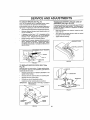
TO ADJUST
STEERING
WHEEL
ALIGNMENT
TO START ENGINE WITH A WEAK BATTERY
(See Figs. 29 & 30)
if steering wheef crossbars are not horizontal (left to right)
when wheels are positioned straight forward, remove
steerlng wheel and reassemble per instructions in the
Assembty Section el this manual.
FRONT
WHEEL
ateexplosive gases, Keepsparks, flame
and
smokingLead,acid
materialsbatteries
away from
batCAUTION;
gener_
teries. Always wear eye protection
when around batteries.
TOE-IN/CAMBER
The front wheel toe4n and camber are _ot adjuslable on
your unit If damage has occured to affect the front wheel
toe4n or camber, contact your nearest Sears Service
Center,
if your battery is too weak to start the engine, It should be
recharged
If "jumper cables" are used for emergency
starting, follow this procedure:
IMPORTANT:
YOUR UNIT JS EQUIPPED WITH A 12
VO LT NEGATIVE GROUND ED SYSTEM.
THE OTHER VEHICLE MUST ALSO BE
A 12 VOLT NEGATIVE
GROUNDED
SYSTEM.
DO NOT USE YOUR TRACTOR BATTERY TO START OTHER VEHICLES
TO ATTACH JUMPER CABLES -
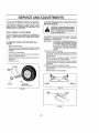
TO REMOVE WHEEL FOR REPAIRS (See
Fig° 28)
Biock up axle securely.
Remove hub cap, retaining ring and washers lo aJlow
wheel removal (rear wheel contains a square key- Do
not lose).
Repatr tire and reassemble.
'
On rear wheels only: align grooves in rear wheei hub
and axle. insert square key,
Replace washers and snap retaining ring securely In
axle groove,
.
Replace hub cap,
'
Connect each end of lha RED cable to the POSITWE
(+) terminal of each battery, taking care not to short
against chassis.
•
Connect one end of the BLACK cable to the NEGATIVE (*) terminal of tully charged baltery.
Connect the other end of the BLACK cable to a panel
belt on the _eft side of the chassis, away from fuel tank
and battery.
TO REMOVE CABLES, REVERSE ORDER •
BLACK cable first from teft side of chassis and fully
charged battery
RED cable last from both batteries
q
HUB CAP
SQUAREKEY
(REARWHEEL ONLY)
"NEGATIVE'
(9
(,)
FIG. 29
FIG. 28
PANEL
_
aOLT__€_)_-.
FIG. 30
22
_//
SERVICE AND ADJUSTMENTS
=
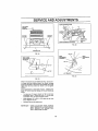
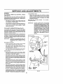
TO REPLACE FUSE (See Fig° 31)
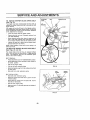
TO REMOVE HOOD AND
(See Figs_ 32 and 33)
.
Raise hood.
Replace with 30 amp automotive-type p_ug_.tnfuse. The
fuse holder is located in the engine compartment, dtrectty
in front of the heat shleld,
GRILL
ASSEMBLY
Unsnap headlight w_reoonnector.
Carefulty remove springsfrom hinge brackels.
Stand at side of tractor. Grasp hood, rift forward and
Hitoff hinge brackets.
To reinstall, slide hood pivot rod into slot in hinge
brackets, andcarefully reinsfall hoodspdngs
HOOD
,HEADLIGHT
HOOD SPRING
FfG, 31
TO
REPLACE
HEADLIGHT
BULB
Raise hood_
Puil butb holder out of the hole In the backside of the
grill,
Replace butb In holder and push bulb holder securely
back tnto the hole in the backside of the grill
=
Close hood,
HINGE BRACKET
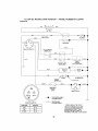
INTERLOCKS AND RELAYS
FIGs 32
Loose or damaged wiring may cause your tractor to run
poorly, stop running, or prevent it from starting,
Check wiring See efectrical wiring diagram tn Repair
parts section of this manuel
HOOD PWOT ROD
HINGE BRACKET
FIG. 33
23
SERVICE AND ADJUSTMENTS
ENGINE
TO
ADJUST
ACCELERATION
THROTTLE
CONTROL
CABLE
(See Fig. 34)
The throttle controJ has been preset at the factory and
adjustment should not be necessary. Check adjuslment as
described below before loosening cable tf adjustment is
necessary, proceed as follows:
High speed stop is factory
damage may result
With engine no!, running, move throttle oontroE lever
from SLOW to CHOKE position Slow[ymavelever
from "CHOKE" to "FAST" position
,
Check that hole in throttle lever and hole In plate line up.
If holes "A" are not a_lgned, loosen clamp screw and
move throtlte cable until holes are aligned, Tighten
clamp screw securely
TO
ADJUST
CARBURETOR
(See
F|g.
IMPORTANT:
34)
The carburetor has been preset at the factory and adjust.,
ment should not be necessary,, However, minor adjust*
ment may be req uired to compensate for differences In fuel,
temperature, altitude or load, If the carburetor does need
adjustment, proceed as felfows:
in general, turning the mixture screws In (clockwise) decreases the supply of fuel to the engine giving a leaner lust/
air mixture,
Turning the mixture screws out (counterclockwise) increases the supply of fuel to the engine giving
a richer lust/air mixture
IMPORTANT;
DAMAGE TO THE NEEDLES AND THE
SEATS IN CARBU RETOR MAY RESULT
IF SCREWS ARE TURNED iN TOO
TIGHT
PRELIMINARY
SETTING -
TEST -
Move throttle control lever from "SLOW" to "FAST"
position. If engine hesitates or dies, turn high speed
mixture screw out (counIarclockwtse) 1/8 turn. Repeat
lest and continue to adjust, if necessary, unlit engine
accelerates smoothly,
adjusted.
NEVER TAMPER WITH THE ENGINE
GOVERNOR, WHICH IS FACTORY SET
FOR PROPER ENGINE SPEED, OVERSPEEDING THE ENGINE ABOVE THE
FACTORY HIGH SPEED SETTING CAN
BE DANGEROUS,
iF YOU THINK THE
ENGINE-GOVERNED
HiGH SPEED
NEEDS ADJUSTING, CONTACT YOUR
NEAREST
AUTHORIZED
SERVICE
CENTER,
WHICH
HAS
PROPER
EQUIPMENT
AND EXPERIENCE
TO
MAKE ANY NECESSARY
ADJUST.,
MENTS.
THROTTLE CABLE
CLAMP SCREW
LEVER
Be sure you have a clean air filter and the throttle
control cable is adjusted propedy (see above)
With engine off turn high speed mixture screw in
(clockwise) c_oslng it finger tight and then turn out
(counterclockwise)
f -112 turns,
Turn idle mixture screw in (clockwise) closing finger
tight and then turn out (counterclockwise)
1 turn.
FINAL SETTING
-
Start engine and allow to warm for five minutes. Make
final adjustments with engine running and shift/motion
control lever in "NEUTRAL" position_
With throttle control tever in "FAST" position, turn high
speed mixture screw In (clockwise) unti! engine begins
to die then turn out (counterclockwise) untll engine runs
rough. Turn screw to a point midway between those
two positions,
With throttle control lever in "SLOW" position, turn idle
mixture screw in (clockwise) unfit engine begins to die
and then turn out (counterclockwise) until engine runs
rough. Turn screw to a point midway between those
two positions
With throttte control lever in "SLOW" position, engine
shouldidle at 2100 RPM If engtne idles too slow, move
throttle control lever above Idle end turn Idle speed
screwfn (clockwise) oneturn. Setthrotttecontrollever
at "SLOW", Repeat until satisfactory idle is altained_
If engine idles too fast in "SLOW" position move throttle
control lever above idle and turn idle speed screw out
(counterclockwise)
one turn, Set throttle control lever
at "SLOW" Repeat untO!satisfactory idle is attained.
Do not adjust -
iDLE
MIXTURE
SCRE3N
HIGH SPEED
MIXTURE
SCREW
FIG_ 34
24
STORAGE
CAUTION:
FUEL SYSTEM
Never store the tractor with
IMPORTANT,'
IT IS IMPORTANT TO PREVENT GUM
DEPOSETS FROM FORMING IN ESSENTIAL FUEL SYSTEM PARTS SUCH AS
L.
ALSO, EXPERI ENCE INDICATES THAT
TRACTOR
FORMATION
OF ACIDS
DURING
STORAGE ACIDIC GAS CAN DAMAGE
THE FUEL SYSTEM OF AN ENGINE
WHILE IN STORAGE
mower
Remove is m°Werstoredfmm
to be
IrrC?pef_rdwol?t_resler_gaen_ i_thoe_
°UghulYn'drer_Ve_t_od_'iggeaa_eo'ol_%Vea_'o_t_r?ais
ve biadea
or rust
preventative,
Store in a clean, dry area_
Cleane en_olnra_t_h_(Sre_n'_)_N,NG"
Drain the fuel tank.
in tha Ma,nta-
Start the engine and lel it run until the fuel lines and
carburetor are empty
Inspect and replace bs!la, ff necessary (See belt replacement instructions In the Service and Adjustment_
section of this manual),
,
Lubricate
manual.
.
Be sure that all nuts, bolts and screws
•
as shown tn the Maintenance section of this
Never use engine or carburetor cteaner producls in the
fuel tank or permanent damage may occur
Use fresh fuel next season
ere securely
_r,S_own
e _ '_sePp_
_t m __ ;g ePsa_
taSr
_° r damage' breakage
gas tank and carburetor
BATTERY
ff using fuel stabilizer
ENGINE OIL
Fully charge the battery for storage,
manuat)
After a period o! time In storage, battery may requira
recharging
CYLINDERS
*
Remove spark plug(s)
,,
Pour one ounce of oil through spark plug ho_e(s) into
cylinder(s)
'
Tou_i_stg_tui_en
okel
Yt° "START" P°Siti°n for a few sec°nds
nance section of this manual)
After cleaning, leave cabfes disconnected and place
cables where they cannot come in contact with battery
terminals.
Replace with new spark plug(s)
Be sure battery drain tube la securety attach ed to drain
in battery tray,
OTHER
Do not store gasoline from one season to another
will cause your unit to rust
IMPORTANT=
NEVER COVER TRACTOR
GINE AND EXHAUSTAREAS
WARM
25
WHILE ENARE STi LL
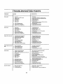
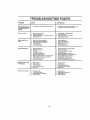
TROUBLESHOOTING
POINTS
PROBLEM
CAUSE
wet netstart
1
2
3
4
&
8
7,
Out of fuel
Engine not "CHOKED" preper;y
Engfne flooded
Bad spark plug
Dirly aft fit{or
Dirty fuel f_Itar
Waler In fuel
t
2
&
4
&
6.
7.
8
g
tO,
Loose or damaged w]dng,
Carburetor oul af adjustment
Engine valves out of adjusLmenl,
8
g10
1
2
3
4
5
8
7
8
Dirty air f_ter,
Bad spark plug
Weak or dead battery
Dirty fuel filter
Stale or didy fuel,
Loose or damaged wldng
Carbu rater oul of adjustment,
Englne valves out of adjustment
Hard to start
Engine wit! not turn over
1
2
3
4
5,
6
7
8
g
tO
Engine clicks but wtg net
start
t
2
3
4
Loss of power
1
2
3
4
5
6
7
B
g
10.
11,
12.
t3,
!4
15,
Excessive vibration
1
2,
3,
CORRECTION
1,
2
3,,
4
5.
6
7.
8
Clutchrorake podaf net dapresaod
Attachment cMch is engaged
Spa_k plug wire Is disconnected
Weak or dead batlery
Blown fuse
Corroded battery terminate
Loose or damaged wiring
Faulty _gntOoeswitch
Faully so}enid or starter
Foully operator presence ewtlah(ea)
Flfl feet tank,
See TO START ENGINE In operation eecDon
Watt severalminutes before attempting to start
Replace spark plug.
Clean#eplace air filler.
Replace feet filer.
Dr_n feet task and carburetor, refill tank wlLhfresh
gaaaiina and replace fuelfiller
Check aft widng.
Contact Sears Service Center,
Contast Se are Service Center,
Claan#aplace air frier.
Reptace spark ptug
Recharge or replace batter/
Replace fuel f}fter
Drain fuel tankend refill
wl_ fresh gasollna
Check a}Iwldng,
Contact Seam Service Center
Contact Sears Service Center
1
2
3
4
G
6
7
8
9
t0
DepressCIulch/bmkepedat,
Disengage attachment clutch
Connect wire to spark ptug
Recharge or repiece batteq/,
Replace fuse
Clean batter./I_rminala
Check alt wiring
Chsckheplace Ignition swkch
Check/replace sofenoldorstader
Contact Sears Servtce Center
Weak or dead battery
Corroded battery terrain!!B.
Loose or damaged wldng
Foully _otanafd or atader
1
2,
3
4,
Recharge or replace baltory
Clean baltary terminals
Check ellwidng,
Cheddreplace aolanoldor starter
Culling too mec:_ grass/too fast
Throttle tn "CHOKE" poelIIoo.
Bulid.,up of grass,leaves end trash under mower
Ditty air filter,
Low ell tavafldirty oli
Faufty spark plug
Didyfuel filler
Stale or dirty fuel
Watarlnfuel
I
2
3
4
5
O
7
B
g
Set In "Higher Cut" positlon#educe speed
Adjuatthrotge control
Clean underside of mower housing
Cleanlrepleaa air fl11_r
Check olIlevel/c,hange ell
Clean and regap or change spark plug
Replace fuel lIltar
Drafn fuel t_k and refillwith fresh gasoline,
Drain fuel lank end carburetor, relill lankw}th #esh
gasoline and replace fue! filler
Connect and _ghtee spark plug wife
Clean engine alrecrean/flns
CleanHepleoe muffler,
Check all wiring,
Contact Seat's Service Canter
Contact Seats Service C_nter
Spark ptug wire loose
Dirty aegina air sareentflns
Dlrty/elagged muffler,
Loose or damaged wiring
Carburetor out of adjustment
Engine valves out of adIustreent
10
I t,
t
2r
13
14
15
Worn, bent or loose blade
Sent blade maedret,
Looee/demaged part(s)
1
2
3
26
Replace blade, Tighten blade boll.
Replace blade mandret,
Tighten loose part(a), Replace damaged parts
'
'L
'
•
TROUBLESHOOTING
,I.I,,L
PROBLEM
,ll,ll,,llll
POINTS
, i
CORRECTION
CAUSE
Engine oongnuoe to run
when operator ]seres seat,
with attachment ctutch
engaged
1
Faultyopereior-eafetypresencec_ntmteys_m
L
POOr
1
2
3
4
Worn, bent or loose blade
Mower deck not tevet,
Build.up of grass, teavee, and trash under mower
Bent blads mandrel
2,
3
4
"F
Obsb_oUon
2
3
Mower drive belt out of adjustment
Worn/damaged
mower drive bolt
4
5
Frozen Idler put{ay
Frozen blade mendral
cut
- uneveil
Mower blades will not
rotate
_ r,
Poor grass discharge
Headlight(e} not worktng
(if eo equipped)
Batterf wll! not charge
I
2
3
4
5
6
7
8
g
tO
Checkwtdng, swltehee endconnectione If not
corrected, con_estSears Service Center.
Replace blade 13ghten blade boil
Levet mower deck.
Oean underside of mower housing
Replese blade mandrel
In clutch mechanism
2
3
4
6
Engine speed tea slow
Travel speed too test
Wet grass
Mowerdeeknotlevei
Low/unevon tire air pressure
Worn, bent or loose blade
Build.up of grass, leaves and trash under mower
Mower drive
bolt worn or out of adjustrr_et
Blades fmpmpe#_tlns_al}ed
improperbiades used
t
2
3
4
5
6
7
B
9
!0
Removemower
obstrucUoo
Adjust
ddve bait.
Replese mower drive bell
Reptess idler pulley
Replace blade mandrat
Flace thmltle conb'olIn"FAST" pesltlon
Shift to _fower speed,
Allow grass to dry before mowing
Level mower deck
ChecktJres for proper atrpressure,
Repleseleharpon blede T_ghten blade boil
Cleon underaideofmower housing
Replace/adjust
mower drivebelt
Relnstaff
bladessharp edge down
Replace w_ blades listed In thla manual
2
3
4
5
Swllch is "OFF"
Bulb(e) burned out
Faulty light swtlch
Loose or damaged wlffng
Blown fuse.
2
3
4
5,
Turn switch "ON"
Replace bulb(s)
Check/replace light ewttoh
Check wiring and connections
Replace fu_e
1
2
3
4
Bad battery celt(s)
Poor C_bte conneelJone
Faulty regulator (if so equipped)
Faulty a_tematot
2
3
4
Replace baffery
Cheek/clean_l connesl$ons
Replace regulator
Replesa eltemaler
27
SERVICE NOTES
28
12.5 HP 38" RIDING
LAWN TRACTOR
- - MODEL
NUMBER
917.254791
SCHEMATIC
BATTERY
"°°
Wt_II"E
O' Z}
_USE30 AMP
:
:
:
STARTE_
OLENOID
_l"r_ .....
iGNITiON
SWITCH
J
CLUTCHtBRAKE
(PEDAL UP)
I
I
......
I
BLACK
BLACK
I
_
I
8L,_CK
!
BLACK
I_
f
SEAT
SWITCH
{NOT OCCUPIED)
ATPMENTCLUTCH
(CLUTCHOFF)
B_CK
IGNITION
UNIT
_._,4psoc,f
_TTERY
DIODE
_'_-)
&.\.
SPARK
PLUG Q--
ALTERNATOR
_N L_NE}
BROWN
HEADLIGHT
SWITCH
(OFF)
HEAD UGHTS
-"'4[_NON-REMOVABLE
CONNECTIONS
IGNITION
POSITION
OFF
SWITCH
--_.)_-_REMOVABLE
CONNECTIONS
WIRING INSULATED
CIRCUIT
M + G
ON
B+L
START
B +S
CLIPS
NOTE: IF WIRING INSULATED
CLIPS WERE REMOVED FOR
SERVICING OF UNIT, THEY
SHOULD BE REPLACED TO
PROPERLY SECURE YOUR WIRING
29
,
REPAIR
PARTS
12.5 HP 38"
RIDING
LAWN TRACTOR
- - MODEL
NUMBER
917.254791
ELECTRICAL
19
28
121
I
41
3O
REPAIR
PARTS
12.5 HP 38" RIDING
LAWN TRACTOR
- - MODEL
NUMBER
917'.254791
ELECTRICAL
KEY PART
NO, NO,
1
2
3
4
5
6
7
8
9
10
1I
12
13
t4
15
16
17
18
19
20
21
22
23
24
25
7662J
127441X
129794
109310X
110712X
104445X
7603J
109596X
STD365402
108824X
8TD551125
73350400
74780408
STD541425
t08423X
11050400
719J
5114J
109553X
4207J
74760412
STD551025
STD541025
12t265X
t02476X
KEY PART
NO. NO,
DESCRIPTION
Bulb, Light
Harness, Light Socket
Harness, Wiring
Key, Molded
Switch, Light
Switch, Interlock
Tray, Bailer/
Clamp, Hose
*Switch, Ignition
Fuse
"Washer, Lock 1/4
Nut, Hex, Jam I/4.20
Bolt, Hex t/4-20 x 1/2 Grade 5
*Nul, Keps I/4-20
Cable Assembly
Washer, Lock, ExtematTooth
1/4
Cover, Term!hal
Cable, Batter!
Switch, Inlerlock
Cable, Batter/
Bolt, Hex 1/4-20x3/4
*Washer
9/32 x 5/8 x t6 Gauge
* Nut, Hex 1/4-20
Battery
Guard, Terminat
A
26
27
28
29
30
31
32
33
34
35
36
123198X
STD551125
72240460
109081X
123620X
124211X
7192J
105687X
121305X
STD601005
74641008
37
38
39
40
41
--
73951000
4171R
121264X
!"{150400
123620X
101539X
--
130898
* STANDARD
Nut, Wing 1/4-20
*Washer, Lock, Heavy He!Ical
Bo_t, Carriage t/4-20x
7-1/2
Solenoid
Cover, Ignition
Nut, Ignition
Cable, Tie
Tube, Plastic
Switch, Plunger
* Screw, Tap Hex Hd. #10 x24
Screw, Slotted Pan Head
#10,.32 x 1/2
Nut,Keps #10-32 x l/2
Ctip, Insulated
Batter/Caps
Set
Washer, Lock, InternalToolh
Cover, Ignition Switch+
Sheet, Instruction, Tractor, t5
Slope
Owner's Manual
HARDWARE
-- PURCHASE
NOTE: All component dimensions
1 _nch = 25.4 mm
B
12
DESCRIPTION
C
13
_14
D
36
_37
31
35
Spring
UNC
1/4
_
LOCALLY
given in U.S inches
T"
rc
UJ
m
Z
.J
ll(
0
0
0
O:
IZ
_z
or)
\
W
ffl
,.r
u
32
"it-.
O_
t-.
in
%.-
C_
e4
n"
U.I
m
,_
_n
:D
Z
_X
-J
_XXXXXXXXXXX_
_oooXXXXXXX
o
ill
0
0
!
!
R
= ®=,@
ro
,<
IZ
K
Z
Q
rr
;o
o @_@@
n
-Ira
< @_
n-
W
if}
<
33
REPAIR
PARTS
12.5 HP 38" RIDING
LAWN
TRACTOR
- - MODEL
NUMBER
917,254791
DRIVE
64
88
/
16
OPT)ONAL
EQUIPMENT
Sp_,r k Arresler
73
34
34
1
REPAIR
PARTS
12,5 HP 38" RIDING
LAWN TRACTOR
- - MODEL
NUMBER
917.254791
DRIVE
KEY PART
NO. NO_
1
129795
2
4
5
6
7
8
9
10
11
t2
14
t05731X
STD551!43
71130720
125907X
122983X
125593X
101326L
t23528X
STD551131
129921
17490620
t5
16
STD551125
127050X
17
18
19
20
21
22
23
24
STD523727
STD541437
12000003
123666X
12000026
109167X
STD623710
17490512
26
27
28
30
31
127275X
73530400
._2-,"-9_X
129797
123793X
32
33
34
35
36
37
38
39
40
41
42
127274X
STD523707
121748X
106933X
127270
71040412
106362X
STD561210
19171216
104777X
17490612
43
44
45
46
47
48
49
50
19131312
129796
109070X
4470J
123674X
127783
123789X
STD523715
KEY PART
NO. NO.
DESCRIPTION
Engine, 12.5 HP, Tecumseh
Model Number 143.416082
Pulley, Engine
*Washer, Lock, Heavy Helical Spring
Bolt, Hex 7/16-20 x 1-1t4
V-Beft, Drive
Muffler
Gasket
Defiecfor, Muffler
Screw, Cap, Hex 5/16-18 x 5/8
*Washer, Lock 5/16
Keeper, BeEt, Engine
Screw, HexWasher Hd., Thd. Roll.
3/8-16 x 1-I/4
*Washer, Lock, Heavy Helical Spring
Transaxle, Tecumseh, 5 Speed,
930 Peerless
*Bolt, Hex 3/8-16x2-314
* Nut, Crownlock 3/8-16
E-Ring
Pulley, Transaxle
Ring Retainer
Bracket, Transax e
*Bolt, Hex 3/8-16 x 1
Screw, Hex Washer Hd, Thd Roll.
5t16-18 x 3t4
Keeper, Belt, LH.
Nut, Nylok t14-28
Shaft, Shifter Assembly
Spring, Compression
Rod, Tie
. Keeper, Belt, RH.
Bolt, Hex 3/8.16 x 3f4
Washer 25132 x 1-5/8x 16 Gauge
Knob, Shift
Rod, Shift
Bolt, Hex 1/4-28x3/4
Washer, Shift Plate
*Pin, Cotter 1/8x 1
Washer 17/32 x 3/4 x16 Gauge
Retainer, Belt
Screw, Hex Washer Hd.,Thd. Roll
3/8-16x 3/4
Washer 13/32 x I3t16x 12 Gauge
Fan, Pump, Oil
Retainer, Belt
Spacer
idler, Flat
Idler, Groove, Plastic
BellcrankAssemb_y
*Boil, Hex 3/8-16x 1-1/2
5I
52
53
54
55
56
57
58
59
60
61
62
63
64
65
66
67
68
69
70
71
72
73
74
76
77
78
79
60
81
82
105709X
1108!2X
12000039
105710X
8TD56!210
127272X
110437X
106888X
73350600
19131316
125638X
124236X
122424X
8883R
121749X
STD571810
t20183X
STD580025
127222X
89192
65139
123969X
106108X
109502X
12000001
121520X
12669tX
110422X
105706X
123205X
17030808
83
84
85
86
87
88
91
95
96
97
96
99
100
101
-=-
123782X
130849
19091210
11050600
7152J
12185tX
104757X
11150400
74760540
19111 tt6
73680500
127285X
2228M
19211816
129783
10863tX
* STANDARD
NOTE;
A
B
D
E
F
DESCRIPTION
G
Spring, Return, Clutch
Washer, Hardened
Ring, Ktlp
Link, CIutch
*Pin, Cotter 118 x 3/4
Bushing, Pivot
Rod, Brake
Spdng, Rod, Brake
Nut, Jam 3/8-16
Washer 13/32 x 13/16 x 16 Gauge
Rod, Brake, Parking
Cap, Plunger
Shaft, Foot Peda{
Cover, Pedal
Washer 25/32 x 1-114x 16 Gauge
*Pin, Rol! 3116 x 1
Bearing, Nylon
Key, Square 2.5 x 1845/!865
Pipe, Ot! Drain
Cap, Valve
Stem, Valve
Tire, Rear
Rim Assembly, Rear
spacer
E-Ring
Strap, Torque, Transaxle
Washer
53 x 1.25 x .059
Spring, Brake
Bearing
Retainer, Belt
Screw, Spider Lock
#8-18 x 1/2 AABTPS
Spring, Torston
Arm, Shift
Washer 9/32 x 3/4 x 10 Gauge
Washer, Lack, External Tooth 3/8
Tube, Tire
Spark Arrestor
Cap, Axle
Washer, Lock, Internal Too h 1/4
Bo_f, He× Fin. 5/16-18 UNC x 2-1/2
Washer 11i32x11116x16Ga
Nut, Crownlock 5/16-18
Strap, Torque, L.H.
Key, Woodruff #9
Washer 21/32 x 1 x 16 Ga
Decal, Logo, Engine
Decal, II
HARDWARE
o - PURCHASE
Att component dimensions
1 inch = 25.4 mm
H
K
L
M
'24
_97
_18
98
(5_43 ._43
@t8
35
_11
@86
LOCALLY
given in U..S inches
REPAIR
PARTS
'12.5 HP 38" RIDING LAWN TRACTOR - - MODEL NUMBER 917.254791
STEERING
AND FRONT AXLE
I
J
36
REPAIR PARTS
12.5
STEERING
HP 38" RIDING
LAWN
TRACTOR
- - MODEL
NUMBER
917,254791
AND FRONT AXLE
KEY PART
NO. NOo
KEY PART
NOo NOo
DESCRIPTION
1
2
3
4
5
6
7
8
9
10
126604X010
74180512
73510500
109816X
424434X
STD522510
!26684X
124417X
126595X010
17490608
Dash
Screw, ]"russ Head 5/16-18x 3/4
Nut, Keps 5/46-18
Nyllner, Snap-In
Control, Throttle
*Screw, Hex, Thd. Cut, 1/4-20x 5/8
Washer l/4xS/Sx16Gauge
Boot, Steering Shaft
Saddle
Screw, HexWasher Hd., Thd Rot!
3/8_t 6 x 1/2
41
42
44
46
46
47
48
49
50
51
52
1t
13
t4
!5
I6
17
18
19
20
22
126471X
100710L
STD541350
100712K
100713N
!00711L
STD551125
71070410
t26938X
STD611005
24
25
26
124373X
124036X
174906t2
53
54
56
56
57
58
59
60
61
63
65
67
69
--
27
28
29
30
31
32
34
35
35
38
39
40
6266H
124034X
124035X
12000029
57079
124038X
104757X
5479J
124033X
49212010
74761060
I05669X
Cllp, Insulated
insert, Steering Whee
*Locknut, Hex, Jam 1/2-20
Washer 2-1/4
Wheal, Steering
Adapter, Steering Wheel
*Washer, Lock 1/4
Screw, Socket Hex 1/4-20x 5/8
Bumper, Heed
*Screw, Hex, Self-Tapping
#10-16 x 1/2 Type ABTPS
Bushing, Steenng
Bracket, Steering
Screw, He× Washer Hd ,Thd. Roll
3/8-16 × 3/4 Type TT
Bearing, Thrust
Gear, Sector
Shaft, Support
R{ng, Klip
Washer, Hardened
Shaft, Steering, Lower
Cap, Axle
Plug, Button
Shaft, Pitmen
Washer 21/32 x !-1/4 x 10 Gauge
Bott, Hex 5/8-11 x3-3/4
Axle, Front
A
B
110438X
73601000
124037X
3366R
105715X
t20754X
19131416
76020412
8TD551t37
73610600
128122
I05656X
I05654X
278H
9040H
106732X
59192
65139
124157X
19272016
59904
STD554231
!2t748X
121232X
425879X
108456X
DESCRIPTION
Spacer, Bearing, Front Axle
Locknut, Flange 5/8-11
Gear, Pin{on
Bearing
Rod, Tie
Bushing
Washer t3/32 x7/8 x 16 Gauge
Pin, Cotter t/8 x 3/4
*Washer, Lock 3/8
Nut,Fin Hex 3/8 x 24UNF
Link, Drag
Spindler L H.
Spfndie, R.H
Fitting, Grease
Bearing, Flange
Rim, Front (Incl. 2 each Key No 56
Cap, Valve
Stem, Valve
Ttre, Front
Washer 27/32 x i-!/4 x 16 Gauge
Tube, Front
*Washer, Lock, Internal Tooth 5/16
Washer 25/32 x 1-5/8 x16Gauge
Cap, Spindle
Decal, Steertng Wheel Cap
Decat, Instruction, Operating
* STANDARD HARDWARE
- - PURCHASE
NOTE; AI{ component dimensions
1 inch = 25.4 mm
D
F
H
26 <_2
@ 65
_3
_3
37
LOCALLY
given In U S Inches
REPAIR PARTS
12_5 HP 38" RIDING
LAWN
TRACTOR
- - MODEL
NUMBER
917.254791
LIFT ADJUSTMENT
16
C
F 9
13 _'__11
10
j
!..
/
B
i
31
i
13
45
44._,
40
43
45
47
38
REPAIR
PARTS
12.5 HP 38" RIDING
LAWN TRACTOR
- - MODEL
NUMBER
917.25479t
LIFT ADJUSTMENT
KEY PART
NO. NOo
I
2
3
4
5
6
7
8
9
10
1t
12
13
14
124429X
106932X
106451X
73680600
106452X
19171516
17021008
106447X
123549X
109202X
101335K
124028X
123487X
17490612
15
16
17
18
19
20
21
22
23
19(}91416
122795X
!21794X
124031X0t2
19211416
STD581062
122365X
122512X
17490412
24
25
26
27
28
29
80
31
32
105736X
5320R
120183X
105839X
105838X
STD551025
122507X
123650>(
122364X
KEY PART
NO, NO.
DESCRIPTION
Lever, Clutch, Mower
Knob
Bolt, Shoulder
Nut, Crowntock 3/8_t6
Bracket, Switch, Interlock
Washer !7/32 x 15/16 x 16 Gauge
Screw, He×,Tapping
#10-24
Support, Lever, Clutch
Cap, Fuel
Tank, Fuel
Une, FtJel
Grommet
Clamp, Hose
Screw, Hex Washer Hd., Thd Rott
3/6_16 x 3/4
Washer 9/32 x 7/8 x 16 Gauge
Panel, Dash, LH
Cover, Access
Panel, Dash, R.H.
Washer 21/32 x 7/8 x t6 Gauge
*E_Rlng
Bulton, Plunger
Spring, Compression
Screw, Hex Washer Hd, Thd. Roll.
1/4.20×3/4
Shield, Heat
Clip, Insulated
Bearing, Nylon
Receptacle, ti4Tum
Retainer, 1/4 Turn
*Washer 9/32 x 5/8 x 16 Ga.
Shaft, Lift
Stud, 1/4Turn
Plunger
B
C
33
34
35
36
37
38
39
40
41
42
43
44
45
47
46
49
60
51
52
63
54
65
57
59
60
61
62
DESCRIPTION
125631X
4939M
I10029X
110447X
110448X
121596X
105848X
121599X
I06308X
STD541050
9t35R
19171516
4921H
106444X
STD523707
109726X
STD561210
t24444X
19131410
1225t4X
105767X
124446X
108236X
110739X
73980600
73360700
73710700
122581X
Y' STANDARD
Grip, Handle
Retainer, Spring
Link, Lift
Trunnion, Lift
Link, Lift, Adjustable
Arm, Suspension, RH
Bolt, Shoulder 3/8.16
Arm, Suspension, L.H
Trunnion, Uft, Lower
*Nut_ Hex 1/2-!3
Retainer, Spring
Washer t7/32 x 15/16 x 16 Gauge
Retatnero Spring
Bracket, Bellcrank
* Bolt, Hex 3/8-t 6 x 3/4
Bellcrank Assembly
* Pin, Cotter 1/6 x 3 4
Rod, Clutch, Primary
Washer 13/32 × 7/6 x 10 Gauge
Rod, Assembly, Lever
Pin, Groove
Spring, E×tention
Bracket, Switch
Washer, Spring
Nut, Ftange_c_k 3/6 x 16
N[._t,Hex, Jam 7/16-20
Nut, Orownlock 7/16-20
Couple, Lift, Lever
HARDWARE
* - PURCHASE
NOTE: All component dimensions
1 inch = 25.4 mm
D
E
'_59
60
39
_4
F
LOCALLY
given In U-S inches
REPAIR
PARTS
12.5 HP 38" RIDING
LAWN
TRACTOR
- - MODEL
NUMBER
917.254791
38" MOWER
44
K
46
44
A
CC
54
/
55
67
48
67
JI
D
G
40
41
4O
REPAIR PARTS
12.5 HP 38" RIDING
LAWN TRACTOR
- - MODEL
NUMBER
9'17.25479'1
38" MOWER
KEY PART
NO. NO.
KEY PART
NO. NO,
DESCRIPT|ON
1
2
3
4
5
6
7
8
9
10
fl
13
14
15
16
17
18
19
20
21
22
24
25
27
28
29
30
31
32
33
34
35
36
106085X
121259X
8417J
73680600
19111216
72140505
t05896X
110452X
I06734X
106735X
106736X
105304X
105662X
105744X
105872X
109835X
STD523707
73680500
109698X
109597X
STD533107
I09503X
109604X
126756X
74760632
127163X
106902X
123688X
106613X
102669X
t21687X
100668L
17490614
37
17490620
38
39
40
121263X
19132012
STD551137
V-Bait
Housing
Runner, RH
Nut, Crownlock 3/8-16
Washer 11/32x3i4x16Gauge
Bolt, Carriage 5/t6..18 x 5/8
Bracket, Deflector
Nut, Push
Spring, Deflector
Rod, Hinge
Shield, Deflector
Cap, Spr{ng
Link, Parailel
Pin, Hinge, Front
Stop, Link
Pin, Htnge, Rear
*Bott 3/8-16 x 3/4
Nut, Crewnleck 5/t6-18
Bracket, Lift, RH
Bracket, Lilt, LH.
*Bolt, Carriage 5/t6-18 ×3/4
Support, Arm
Stop, Deck, Front
Guide, Belt
Bolt 3/8-16 x 2
Arm, ldlar
Spacer, Retainer
Pulley, Idler
Washer, Wear 1/16
Keeper, Bett
MandrelAssembly
Plate, Support, Mandrel
Screw, Hex Washer Head
3/8q6 x 7/8
Screw, Hex Washer Head
3/8-16X 1-t/4
Blade
Washer 13/32 x 1-1/4 x 12 Gauge
* Washer,Lock
3/8
41
42
43
44
45
46
48
49
60
51
52
53
54
55
56
57
58
59
60
61
62
63
64
66
67
68
69
70
71
72
73
---_
-.......
DESCRIPTION
STD623715
108250X
108235X
4921H
6404J
t24066X
108247X
72140606
106243X
!08241X
105857X
108673X
106576X
106483X
108249X
106456X
100672K
100673L
19131814
74760686
7631J
1911t016
72140610
122314X
STD580907
72110506
74760412
109893X
73680400
110445X
STD551037
122215X
105814X
3713J
121343X
* STANDARD
*Bolt, Hax 3/8-24 x 1-I/2 Grade 5
Spring, Extension
Red, Clutch, Mower
Spring, Retainer
Spacer
Rock Shaft Assembly
Rod, Brake, Primary
Bott, Carriage 3/8-16x 3/4
Bracket, Pivot, R.H.
Bracket, Pivot, L H
Bracket, Suspension, Rear, R.H
Bracket, Suspension, Rear, LH
Brake Assembly
Rod, Brake, Secondary, LH
Rod, Brake, Secondary, RH
Bracket, Brake, Pivot
Spacer, Brake
Bracket, Support
Washer I3/32 x 1 x 14 Gauge
Bolt 3/8-16 x 5
Runner, L,H.
Washer 11/32 x 5/8 x 16 Gauge
Bolt 3/8q6 x 1-1/4
Spacer
* Pin,Cotter 3/32 x 1/2
Bolt,Carriage
5/16-!8x3/4
Bolt, Hex 1/4-20x 3/4
Washer, Special
Nut, Crownloek 1/4-20
P_ate, Support, Mandrel, L.H.
*Washer 13/32 x 13/16x 16 Gauge
Mower Assembly, Complete
Decal, V-Belt, Mower Drive
Decal, instruction, Caution
Decal, Warning
Decal, Safety Standard (Not
Serviced)
HARDWARE--
PURCHASE
NOTE; Atl component dimensions
1 inch = 25.4 mm
A
B
C
13
E
_5
_19
_4
_19
_19
F
G
H
_4
@19
J
K
_4
L
LOCALLY
given in US. inches
M
_)_)7070
@ 71
41
REPAIR
PARTS
12.5 HP 38" RIDING
PEERLESS
LAWN
TRACTOR
TRANSAXLE
-- MODEL
- MODEL
NUMBER
NUMBER
917,254791
143,930-009
TRANSAXLE
7
/
-
9
4
74
/
42
REPAIR PARTS
12,5 HP 38" RIDING
LAWN
TRACTOR
PEER LESS TRANSAXLE
- - MODEL
- MODEL
NUMBER
NUMBER
917.254791
143.930-009
TRANSAXLE
KEY PART
NO. NO.
I
2
3
4
5
6
7
8
9
10
11
12
13
14
15
17
!8
20
21
22
23
25
772108
780086
770102
776260
776219
778139
778138
792136
784352
784355
778229
778113A
778221
778068
778260
786139
786102
792077
792078
792079
788061
792073
26
27
28
29
30
31
32
33
34
35
36
37
38
39
40
40A
792125
792035
788040
780072
780108
780001
792001
788051
780105A
780118A
790003
790007
790006
786026
792076
792128
KEY PART
NO. NO.
DESCRIPTION
Cover, Transaxle
Bearing, Need{e
Case, Transaxle
Shaft, Counter
Shaft & PinfonAssembfy, Output
Gear, Output
Gear, Spur, 15Teeth
Key
Coltar, Shifter
Rod & Fork Assembly, Shift
Gear, Bevel, 42 Teeth
Bevel Pinion, Input
Gear, Bava{
Gear, Bare{ Pinion
Gear, Ring
Pin, Drive
Spacer, Neutral
Bail, Steel, 5/16 diameter
Screw, Set 3/8-16x3/8
Spring
Ring, Felt
Screw, Flanged Hex Head, Thread
Forming 1/4-20 x t-1/4
Ring, Retainer (4 req., pkg. of 2)
R}ng, Retainer
Ring, Retainer
Washer, Thrust
Washer, Thrust
Washer
"O" Ring
Seal, Square Cut
Bushing, Flanged
Bushing, Flanged
Disk, Brake
Plate, Brake Pad
Pad, Brake
Pin, Dowel
Washer, Flat
Washer, Fiat
41
42
790047
792073
43
44
45
46
47
48
49
50
51
52
53
54
55
56
57
58
60
61
62
64
65
66
67
792075
790025
776315A
776135
774690
774691
778191
778124A
778123A
778122A
778209
778230
778126A
778127A
778128A
778163
786081
786082
786123
792074
780139
786067
792085
68
69
70
71
72
74
75
76
77
786086
780051
786118
788069
7861t6
786071
786072
780090
788075
NOTE;
,t3
DESCRIPTION
Lever, Brake
Screw, FIanged Hex Head, Thread
Forming 1/4-20 x 1-t/4
Locknut 5/18-24
Holder, Brake Pad
Shaft, Brake, 4-keyed
Shaft, Input
Axle, 11-151t6
Axle, 16.1t2
Gear, Spur, 37 Teeth
Gear, Spur, 80 Teeth
Gear, Spur, 25 Teeth
Gear, Spur, 22 Teeth
Gear, Spur, 19 Teeth
Gear, Spur, 12 Teeth
Gear, Spur, 20 Teeth
Gear, Spur, 25 Teeth
Gear, Spur, 28 Teeth
Gear, Spur, 31 Teeth
Chain, Rolter (#41 chain, 24 links)
Sprocket, 9 Teeth
Sprocket, 18 Teeth
Plug, Hex Head, Threaded 9/16-18
Washer, Thrust
Spacer
Screw, Flanged Hex Head, Thread
Forming 1/4-20 x 2-1/4
Bracket, Brake Lever
Washer, Thrust
Spacer
Seal, Square Cut
Disk
Spacer
Spacer
Washer, Thrust
Ring, Retaining
AII component dimensions given in U S inches
l Inch = 254 mm
REPAIR
PARTS
12.5 HP 38" RIDING LAWN TRACTOR
- - MODEL NUMBER
917.254791
ENGINE TECUMSEH
- MODEL NUMBER143.416082
ENGINE
44
REPAIR
PARTS
12,5 HP 38" RIDING LAWN TRACTOR
- - MODEL NUMBER 917.254791
ENGINE TECUMSEH - MODEL NUMBER 143A16082
ENGINE
KEY PART
NO. NO!
2
14
15
16
17
18
19
20
25
25B
26
35323A
27652
28277
35324
35520
29916
650548
35521
35319
35326
30322
650561
30
31
35
36
37
38
40
35336A
35327
29826
29918
29216
29642
35776
40
35777
40
35_'78
41
35773
4t
35774
4t
35775
42
42
42
43
45
35779
35780
35781
35772
35330A
46
47
48
50
650908
650882
35313
35314A
51
52
60
61
64
35315
31356
35316
35317
30063
65
70
650128
35711A
72
75
80
31927
35319
35712
KEY PART
NO. NO,
DESCRIPTION
Cylinder Assy (lncf Nee 2 & 20)
Pin, Dowel
Washer, Flat
Rod, Governor
Lever, Governor
Clamp, Throttle lever
Screw, Hex washer hd., 8-32 x 5/!6
Spring, Control
Seal, 011
Baffle, Blower housing
Nut & Lockwasher 8-32
Screw, Hex washer hd Dudok,
1/4-20 x 5/8
CrankshaftAssy
(Counterbalance)
Gear, Counterbalance
Screw, Hex washer hal., t0-32 x 3/4
Washer, ET, Lock
Nut, Lock I0-32
Ring, Retaining
Piston, Pin & Ring Assy (Std) (lncl.
Non. 41, 42 & 43)
Piston Pin & Ring Assy. (.010 oversize) (Incl Nee. 4!, 42 & 43)
Piston, Pin & Ring Assy, (.020 oversize) (lncl. No& 41,42 & 43)
Piston & Pin Assy. (Std} (inct No.
43)
Piston & Pin Assy. (010 oversize)
(Ind. No. 43)
. .
Piston & Pin Assy. (020 overslze_
(Incl, No 43)
Ring Set Piston (Sld,)
Ring Set, Piston (.010 oversize)
Ring Set, Piston (°020 oversize)
Ring, Piston ptn retaining
RodAssy,
Connecting (Inct Nee.
46 & 47)
Bolt, Connecting red
Bolt, Connecting rod
Lifter, Valve
Camshaft (Mechanica_
Compression Release) (Inc! No.
48)
WelghtAssy_, Counterbalance
PumpAssy.
Oil
Extension, Btowerhous_ng
*Gasket, Mounting flange
Screw, Hex washer hd. Seres,
1/4-20 x 1/2
Screw, Hex hdo Sems 10-24 x I/2
Flange, Mounting (Incl Nos_ 72, 75,
80)
PIug, eli drain
Seat, OIl
Shalt, Governor
81
82
83
84
86
35479
35321
35322
29193
650833
68
89
90
91
92
93
100
102
103
31767A
32589
6! 1093
35935
650880
65088t
35135
650872
650814
119
120
121
122
t23
124
35854
35307
730218
792035
35288
650738
t25
125
126
126
127
128
129
130
135
35308
35433
35309
35432
650691
650690
650746
650692
34046
141
142
143
144
145
146
33481
35475
35310
33484
650168
32610A
147 33509
148 34410
149 33510
150 33507
151 33505
152 35295
153 35296
154 850878
155 35297
156 35298
157 28264
158 35468
159 35299B
160 35300
16t 650879
45
DESCRIPTION
Washer, Ftat
GearAssy., Governor
Spool, Governor
Ring, Retaining
Screw, Hex washer hd Powerlok,
1/4.20 x 1-3/16
Spacer, Governor gear
Key, Fiywheel
Ftywheel
Fan, Crankshaft
Washer, Lock
Nut, Flywheel
Solid State Assy.
Stud, Solldstateassy
Screw, Terx hex washer hd Sems,
10-24 x 1
*Gasket, Cytlnder head
HeadAssy,
C_linder
Valve Guide Kit (Inct, 2 of No, 122)
Ring, Retaining
Brace, Inlake pipe
Screw, Hexwasher
splnlock hd.
thread forming, 1/4-20 x 5/8
Valve, Exhaust (Std.)
Valve, Exhaust (1/32" oversize)
Valve, Intake (Std.)
Valve, Intake (1t32" overslze)
Washer, Fiat
Washer, BelleviIIe
Screw Hex hd. 8/16-18 x 318
Screw Hex hd. 5/16-18 x 1_3/4
Resistor Spark plug (Champion RL86C or equivalent)
1"*"O" Ring
Tube, Push rod
Housing, Rocker arm
t*"O" Ring
Washer, Flat
Screw, Flanged hex hd., 1/4-20 x
29/32
t*"O" Ring (intake)
t*"O" Ring (Exhaust)
Cap, Valve spring
Spring, Valve
Cap, Valve spring keeper
t*"O" Ring
Guide, Push rod
Stud, Rocker arm
Arm Rocker
Beadng, Rocker arm
1" NutAsay., Lock (lncl. No 162)
Rod, Push
f*"O" Ring Assy, (IncL No. 161)
Cover, Rocker arm housfng
f* Screw, Truss hd. w/sealing
{ockwasher, 8-32 x 1/2
REPAIR PARTS
12.5 HP 38" RIDING LAWN TRACTOR
- - MODEL NUMBER
917.254791
ENGINE TECUMSEH
- MODEL NUMBER143.416082
ENGINE
r
\
46
REPAIR PARTS
12.5 HP 38" RIDING LAWN TRACTOR
- - MODEL NUMBER 917,254791
ENGINE TECUMSEH - MODEL NUMBER 143.416082
ENGINE
KEY PART
NO. NO.
162
t69
170
171
172
173
174
180
181
182
650903
27896A
28423
28424
28425
35350
650128
35301
650128
650517
184 33263
185 35656
!86 35934
t86A35523
200 35624
202 33502
205 65077
207 35525
209A650902
210
211
27_793
28942
223
792028
224
237
239
240
33515A
35286
33629
35402B
243
245
650875
35403
246A 35_404
250 35405
251 650886
251A650825
252
650887
260
261
35793
30063
KEY PART
NO. NO,
DESCRIPTION
t*Nut, HexJam
* Gasket, Valve cover
Body, Brealher
Element, Breather
Cover, Valve spring box
Tube, Breather
Screw, Hex hd. Same, 10-24 × I/2
Extension, Blower housing
Screw, Hex hd. Seres, 10-24 x 1/2
Screw, Hex hd Seres,
1/4-20x 13/16
* Gasket, Carburetor to intake pipe
Pipe, Intake
Link, Governor
Link, Choke
BracketAssy,,Overrtdecontroi
(IncL Nas. 202, 205)
Spring Compression
Screw Fit, hd., 6-32 x 2t/32
Link, Control bracket
Screw, Hex washer hd., Some,
t0-32 x 7/16
Clip, Conduit
Screw, Hexwasher hd Seme,
10-32 x 3/8
Screw, Hex hd- Sems=
5./16-18 x 7/8
*Gasket, intake pipe
Adapter, Air cleaner
* Gasket, Air cleaner elbow
Body Assy, Air cleaner (IncL No.
239)
Screw, FiL hd. Some, 10.,32 x 6-1/4
Etement, Air eteaner (lnct. No
25tA) (paper)
Filter Poty pro-cleaner
Cove;, Air cleaner
Nut, Wing1/4.20
Nut E.TLockwasher,
t/4..20
(SeaIing)
Screw,Hex
washer hd self-drill,
se_f-tap, 1/4-20 x 1
Housing, Blower
Screw,Hex hd Seres, 1/4-20 x 1/2
262
297478
255
286
287
35290
38792
650936
290 30705
292 26460
292A35864
296 342798
305 35574
307 35499
308 33997
308A35437
310 35576
314 650873
316 511113
321
322
323
325
342
610935
610921
610922
27275
650273
361
30063
363
370
380
395
400
401
420
34148
34346
632490
35763A
35865
35332
730225
DESCRIPTION
Screw, Hex hd, Sems,
5/16-24 x 21/32
Cover, Cylinder head ,'"
Screen Debris
'
Screw, Hex washer hd. shoulder
10-32 x 13/32
Line, Fuel
Clamp Fuel line
Clamp Fuel fiiter to fuel line
Filter, Fuel (tncl Nos 292 & 292A)
Tube, Oil Jill
"O" Ring
Clip, Ott ftll tube
Clip, Ott fill tube
Dipstick, Oil
Screw, Hex hd Sems, I/4-20 x3/4
Cell Assy., Alternator (3 Amp D.C )
(Incl, Nos 321,322 & 323)
Diode
Connector,Body
Terminal, Fema{e
Cftp, Wire
Screw, Hex hd Seres,
5116-18 x 5/8
Screw, Hex washer hd. Sems,
1/4-20 x 1/2
Spring, Coil
Decal, Instruction
Carburetor (IncL No. 184]
Starter Motor (12 Volt)
Gasket Set (lncL Items marked *)
"0" Ring Kit (Incl. items marked 1)
SAE30 4-Cycle Engine OU (quart)
RPM Settings:
High Speed: 3350 - 3650
Low Speed: 1950 - 2250
* indicates Par_s Included
Set, Ref No 400.
in Gasket
1"Indicates Parts included in "O" Ring
Kit, Ref No 401
47
REPAIR PARTS
12.5 HP 38" RIDING LAWN TRACTOR
"- MODEL NUMBER
917.254791
ENGINE TECUMSEH
,. MODEL NUMBER143.416082
ENGINE
KEY PART
NO. NO.
I
2
3
4
5
5A
6
7
8
9
i0
tl
12
632490
632471
632244
632517
650506
630766
630738
650417
632472
6324'73
632429A
630746
631027
631021
13
14
631022
632019
KEY PART
NO. NO.
DESCRIPTION
Carburetor
Shaft & Lever Assy, Throttle
Spring, Throttle return
Shutter, Throttle
Screw, Rd, hal, 4-40 x 3/16
Spring, Idle regulating screw
Spring, Main adjustment screw
Screw, Idle regulating
Shaft & Lever Assy, Choke
Spring, Return
Shutter, Choke
*Plug, Welch
*Plug, Welch
* Inlet Needle, Seat & Clip Assy.
ntc{ No 13)
p, Inter needle
Float, Carburetor
48
15
16
21
22
631024
631867
27110
632239
23
24
25
27
29
29A
30
31
32
630740
632281
631028
631184
631971
631183
630739
631775
632347
DESCRIPTION
* Shaft, Float
* Bowl, Float
Gasket, Bowl-to-body
* Adjustment Screw Assy,, Main
adjustment screw ( InclNo's 5A,
21,23, & 30)
"O" Ring
* Screw, Idle adjustment
* Gasket, Bowl-to-body
Washer
Seal, Dust
Seal, Dust
Washer, Flat
Filling, Fuel
Repair Kit(Incl items marked *)
REPAIR PARTS
12,5 HP 38" RIDING
LAWN
ENGINE
TRACTOR
TECUMSEH
- - MODEL
- MODEL
NUMBER
NUMBER
917,254791
t43,416082
ENGINE
16
18
12
10
9
14
7
6
6
,KEY PART
NO, NO,
DESCRIPTION
....
1
2
3
4
8
6
7
8
9
Starting Motor, Complete
Cover, Dust
Ring, Relatner
Retainer, Spring
Spring, Anti-drift
Gear
Nut & Retainer (tncL No, 2)
Nut, Lock
Cap Assy,, Drive end
Armature
35763A
33451
33842
33430
33431
33432
35693
33450
35894
35895
KEY PART
NO, NO.
49
t0
12
14
15
16
35900
35896
35897
35898
35899
17
18
19
650168
650864
590500
DESCRIPTION
Housing Assy
Brush 8, Spring Kit
Washer, Thrust
Bolt, 16-32 x 4-11/64
Cap & Brush Card Assy,,
Commutator End (IncL Nos- 12, 14,
17, & 18)
Washer, Flat
Nut, Hex
Washer Thrust
SERVICE NOTES
i
ill
5O
SLOPE SHEET
0
tD
_l_
¸
SEAl, S
OWNER'S
MANUAL
MODEL NO.
917.254791
CRAFTSMAN
+
12.5 HP OHV
ELECTRIC START
38" MOWER
5 SPEED TRANSAXLE
LAWN TRACTOR
Each tractor has Its own model number_ Each engine has Its owe1mSdel
number
The Model Number for your tractor
located under the seat
will be found on the model plats
The modet number for your engine wll+ be found on the blower housing of
the engine.
All pads Itsted herein may be ordered from any Sears Service
and most Retaii Stores,
HOW TO ORDER
REPAIR PARTS
WHEN ORDERING
ING INFORMATION:
• PRODUCT
REPAIR
PARTS_ ALWAYS
Centre
GIVE THE FOLLOW+
- LAWN TRACTOR
. MODEL NUMBER - 917+254791
+ ENGINE MODEL NUMBER - 143AI6082
• PART NUMBER
• PART DESCRIPTION
Your Seers merchandise has added value when you constder Sears has
service units nationwide staffed with Sears trained techniclafls ,r profes..
stone! technicians specifically trained to insure that we meet _ur ptedge
to you, we service whet we sell
Sears, Roebuck and Co., Chicago,
130898
03+ 1391
1L 60684 U,S,A.
PRtNTED
IN US A.