1
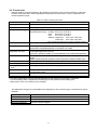
––––
Air-conditioner Control System
Centralized Controller
Model: GB-24A
Instruction Book
Contents
1. Safety Precautions ...................................................1
2. Introduction ...............................................................3
3. Functions ..................................................................4
4. External input/output functions ...................................8
Before using the controller, please read this Instruction Book carefully to ensure correct operation.
Retain this manual for future reference.
This manual describes how to operate the centralized controller. Before using the controller, read the
1 Safety Precautions section carefully to ensure proper installation.
1
Safety Precautions
Safety precautions are provided for your protection and to prevent damage to the controller.
The safety precautions apply to all operators and service personnel.
Safety symbols used in this manual
The following symbols are used in this manual to indicate the type and severity of potential consequences that
may result when given instructions are not followed exactly as stated.
WARNING
Indicates a risk of death or serious injury.
CAUTION
Indicates a risk of injury or damage to the controller.
Retain the Installation Manual and the Instruction Book for future reference. Make sure both the Installation
Manual and the Instruction Book are given to any future air condition system users.
WARNING
The controller must be professionally
installed.
Ask your dealer or an authorized technician
to move the controller.
Improper installation may result in electric shock
or fire or damage to the controller.
Improper installation by an unqualified person may
result in electric shock or fire.
Make sure the controller is securely
mounted so that it will not fall.
Controllers must be disposed of properly.
Contact your dealer for proper disposal
procedures.
To avoid causing damage or fire, do not apply
an AC voltage or a voltage higher than 30VDC
to the M-NET terminal blocks on the
controller.
Do not attempt to modify or repair the
controller.
Modification or improper repair may result in
electric shock or fire.
Consult your dealer when repairs are
necessary.
Never remove the cover during operation.
Touching the charged parts of the controller
may cause severe burns or other personal
injury.
Stop the operation immediately and notify
your dealer if an error code is displayed and
the controller does not operate, or when any
abnormality is noticed.
Continuing the operation may result in damage
to the controller or fire.
If any abnormality is noticed (e.g., burning
smell), stop the operation, turn off the power
supply, and contact your dealer or technical
representative immediately.
Continuing the operation may result in damage to
the controller, electric shock, or fire.
1
CAUTION
Do not use the controller in an environment
high in oil, steam, or sulfuric gas.
These substances may have adverse effects on
the performance of the controller or damage its
parts.
Do not install the controller where there is a
risk of leaking flammable gas.
If the leaked gas accumulates around the
controller, it may ignite and cause an explosion.
Do not wash the unit with water.
Doing so may cause an electric shock or
malfunction.
When installing the controller in a hospital or
communication facility, take appropriate
measures to reduce electrical noise
interference.
Inverter equipment, generators, high-frequency
medical equipment, or radio communication
equipment may interfere with the normal
operation of the controller; or the electrical noise
from the controller may interfere with the medical
practice or cause image distortion and static.
Operate the controller within the temperature
range specification.
The use of controller outside of its specification
may result in serious damage to the controller. Be
sure to check the temperature range specification
in the Instruction Book.
Do not spray insect sprays or sprays with
flammable propellants to the controller.
To avoid the risk of fire or explosion, do not place
flammable sprays near the controller or spray
them directly on the controller.
To reduce the risk of electric shock, install and
wire the unit with the power to the
PAC-SC50/51KUA power supply unit turned
off.
Do not install this controller where an acid or
alkaline solution or special chemical spray is
used frequently to avoid electric shock or
malfunction.
Do not install this controller in a place that
has the potential for steam or dew formation.
Steam or dew formation may cause an electric
shock or a unit malfunction.
Do not touch the PCB (Printed Circuit Board)
with your hand or a tool.
Keep the PCB dust-free to prevent fire or
malfunction.
Do not use the controller for specialized
applications.
This product is designed exclusively for use with
the MITSUBISHI ELECTRIC building air
conditioning control system. The use of this
product with other air-conditioning management
systems or for other purposes may result in
malfunctions.
Use a security device such as a VPN router
when connecting the GB-24A to the Internet
to prevent unauthorized access.
If no security devices are installed, the operation
settings may be changed by an unauthorized
person without the knowledge of the user.
IMPORTANT
Enable the “Automatic restoration after power failure” function on the air conditioning units.
Otherwise, the hold function will prohibit the schedule from being executed, and the units will remain
stopped even after power is restored. Enable this function for the units to automatically resume their
operation after power is restored.
2
2
Introduction
2-1. About this manual
This manual covers the settings that can be made or functions that can be displayed only on the GB-24A.
2-2. Monitoring and operating the air conditioners
To monitor and operate the air conditioners, “GB-24A License Pack” license must be purchased. Purchase
the license from the dealer, and register on the Initial Setting Web or on the Web for Monitor and
Operation.
Refer to Web Browser Operation Manual for monitoring and operating the air conditioners.
The format in which the Web page address for each GB-24A is expressed on the Web browser, as well as
the default user name and password are shown below.
http://[IP address of the GB-24A]/administrator.html
Note: For example, type http://192.168.1.1/administrator.html if the GB-24A IP address is [192.168.1.1].
User
Managers
Default
user name
administrator
Default
password
admin
Notes
● After registering “GB-24A License Pack” Web Monitor,” “Annual Schedule,” “Weekly Schedule,”
“Sending Error Mail,” and “Maintenance Tool Advanced” functions will be available.
● Consult the dealer for information on other functions that require a license (i.e. “Maintenance Tool
(Simple)”).
● Ask the dealer for the Web Browser Operation manual, which covers monitoring and operating the air
conditioners.
● Initial settings, such as making group changes, are covered in the Initial Setting Web manual.
The format in which the Web page address for each GB-24A is expressed on the Web browser, as well
as the default user name and password are shown below.
http://[IP address of the GB-24A]/g-50/administrator.html
Note: For example, type “http://192.168.1.1/g-50/administrator.html” if the GB-24A IP address is [192.168.1.1].
User
Maintenance user
Default
user name
initial
Default
password
init
● It is assumed that the GB-24A will be used on a private network. If connecting the GB-24A to the
Internet, use a security device such as a router with a VPN function to ensure security.
3
3
Functions
Notes
● Refer to the WEB Browser Operation Manual for operating the GB-24A.
● Use the initial setting web to make initial settings via LAN.
3-1. Specifications
Table 3-1. Specifications
Item
Interface
Environmental condition
Dimensions
Weight
Installation Environment
Number of control units
Specifications
M-NET:
30V DC/24V DC;0.13/0.15A
LAN:
Ethernet 10Base-T
Input/output: 12V DC or 24V DC, (External power supply)
Temperature
Operating range: 32 to 104ºF / 0 to 40ºC
Storage range:
-4 to +140ºF / -20 to +60ºC
Humidity
30~90%RH (No condensation)
51/8 (H) ✕ 97/8 (W) ✕ 11/2 (D)in/130 (H) ✕ 250 (W) ✕ 38 (D) mm
2 1/2 lb/1.1kg
In control panel box (indoor)
Install this product indoors.
*This unit is installed and used in a business office, homes or equivalent
environment.
Indoor units, independent OA processing units or LOSSNAY
: 24 units maximum (24 groups maximum)
Number of units (indoor, independent OA processing, or LOSSNAY) in one
group
: 1-16 units
*Note: Indoor units, independent OA processing units, and LOSSNAY
can not register to the same group.
Number of remote controllers in one group
: 1-2
Number of system controllers in one group
: 0-4 (including the number of remote controller in one group)
: 0-3 for groups which have one remote controller.
Number of indoor units interlocked with one OA processing unit or
LOSSNAY
: 0-16 (some types of OA processing unit can only be operated
when interlocked to a maximum of 9 units)
4
3-2. Function list
GB-24A requires a license registration. By registering the license, group or block operation via the Web
browser will be permitted. License registration that permits various functions can be completed on the
license registration page.
Table 3-2. Web monitoring functions
Item
Content
Start/stop
Switching start/stop collectively or for each group
Operation mode
Switching cool/dry/fan/auto/heat/setback collectively or for each group
Temperature setting
Setting room temperature collectively or for each group
Set temperature range Cool/dry: 67ºF-87ºF /19ºC-30ºC
Heat:
63ºF-83ºF /17ºC-28ºC
Auto:
67ºF-83ºF /19ºC-28ºC
Setback: Upper limit: 67ºF-87ºF /19ºC-30ºC
Lower limit: 53ºF-79ºF /12ºC-26ºC
Air velocity
Switching air velocity in four steps collectively or for each group.
Air direction
Switching in four steps vertically and for swing, keep for each group
(Selectable air direction depends on the indoor unit model)
Switching start (Hi/Lo)/stop collectively or for each group when connecting with
interlocked equipment (Lossnay).
(However, ventilation mode can not be selected for the interlocked equipment.)
Selecting the items for which local control is prohibited collectively or for each
group.
(Items include start/stop, operation mode, temperature setting and filter sign.)
Prohibits the scheduled operation from being executed.
Identifies the unit and displays the error.
*Note: Preset temperature range varies on different models.
Start/stop of interlocked
equipment (Lossnay)
Prohibition of local control
Hold
Error display
Filter sign display and
reset
Malfunction history
Annual/weekly schedule
Filter sign display can be reset in each group or collectively.
Malfunction history can be check up to 64 contents in both unit and
communication error.
Using the annual/weekly schedule function by license registration.
Malfunction e-mail history E-mail history can be check up to 64 contents.
* The above specification may be changed depending on the equipment connected or combined.
* The block setting and the registration of block/group names require the initial setting web.
* Without prior notice, the content may be changed.
The table below the types of connectable units. Depending on the model and type, not all functions may be
available.
Model
CITY MULTI
LOSSNAY
Mr. Slim
Room air conditioner
Notes
Requires a M-NET adapter
5
3-3. Setting Functions
Perform initial settings with the Initial Setting Web.
Table 3-3. Initial-setting functions
Item
M-NET address
setting
IP address setting
Initial Setting
Web
GB-24A
Remarks
The default value is 0.
√
√
(Simple setting)
√
Simple settings have priority
over other settings.
√
Presence/absence of
K transmission converter
Connection*1, local operation
prohibition setting, and external
input mode
Function selection
Group registration
√
Registering
interlocked
operation with the
Lossnay unit
√
Switch for start-up
mode
√
Other settings
√
*1: K transmission converter cannot be used. Select “Not used” for the K-control Units setting in the M-NET
Settings window.
1) How to set the IP address with dip switches
IP addresses between 192.168.1.1 and 15 can be set using the 4-pin dip switch on SW2.
Set this switch before turning the power on.
1
2
3
4
OFF OFF OFF OFF
Contents (IP address)
Address that is set with Initial Setting Web.
(Initial IP address setting is 192.168.1.1)
OFF OFF OFF ON Starts from 192.168.1.1
OFF OFF ON OFF Starts from 192.168.1.2
OFF OFF ON
(Inside the cover)
ON Starts from 192.168.1.3
OFF ON OFF OFF Starts from 192.168.1.4
OFF ON OFF ON Starts from 192.168.1.5
OFF ON
ON OFF Starts from 192.168.1.6
OFF ON
ON
ON Starts from 192.168.1.7
ON OFF OFF OFF Starts from 192.168.1.8
ON OFF OFF ON Starts from 192.168.1.9
SW 2
ON
OFF
1 2 3
4
ON OFF ON OFF Starts from 192.168.1.10
ON OFF ON
ON
ON Starts from 192.168.1.11
ON OFF OFF Starts from 192.168.1.12
ON
ON OFF ON Starts from 192.168.1.13
ON
ON
ON OFF Starts from 192.168.1.14
ON
ON
ON
ON Starts from 192.168.1.15
Note
● When setting IP addresses with the Initial Setting Web, set all four dip switches on SW2 to OFF.
6
Notes
● When 15 or fewer GB-24A units are used in the air-conditioning network for, set the IP address via SW2 on the
unit.
● If the set IP address of GB-24A is forgotten, check the IP address that is registered on the monitoring PC (WEB).
GB-24A can be started by changing the setting of SW2 on GB-24A and using an arbitrary fixed
IP address as a temporary IP address. It is recommended to paste a sticker with the IP address on the unit, so
that the IP address of GB-24A is available at all times. Once GB-24A is started up with a temporary IP address,
a new IP address can be assigned to it on the Initial Setting Web.
2) Setting the service switch
The switches must be OFF for normal use. The switch setting change operates when the power is turned
on next time.
SW 1
ON
OFF
1 2 3
1
2
Contents
OFF
OFF
ON
OFF
-
Setting is prohibited.
OFF
ON
-
Setting is prohibited.
Starts with the normal
mode
Remarks
*This setting is for normal use.
*The software can be updated with the
4
ON
ON
Not to be used
Starts with the update
mode
normal mode. If the update fails, or the
software does not work properly use
this setting to update the software
again.
*SW1-3 and SW1-4 are always OFF.
3-4. Service LED display
The LED displays the operation status of the unit as follows.
POWER LAN LINK/ACT
Power supply
LED
LAN
123456
LED1-6
Table 3-4 List of services LED
LED No.
Power supply
LED
LAN
LAN
LED1
LED2
LED3
LED4
LED5
LED6
Items
Contents
Power status
ON
: Power is supplied
/ OFF: Power is cut off
LAN LINK
LAN ACT
Start-up
Operation ON/OFF
Error
(not defined)
(not defined)
M-NET communication
(transmission)
ON
Flash
ON
ON
Flash
Flash
: During LINK
: During communication
: Start-up not completed
: 1 or more units are ON
: Error occurred on 1 or more units
/ OFF: No LINK
/ OFF: No communication
/ OFF: Start-up completed
/ OFF: All OFF
/ OFF: Normal state
: During communication
/ OFF: No communication
7
4
External input/output functions
*External signal input requires the external I/O adapter (Model: PAC-YG10HA), sold separately.
4-1. External input function
(1) The function of external input
• Emergency stop/normal operation, ON/OFF, local remote control prohibit/permit can be controlled for
conditioners on a system with a non-voltage contact signal input from an external input source.
(the dip switches)
• The condition of external input signal is displayed on the operation setting screen for each group.
Table 4-1. Function settings of external input
No.
1
External signal input function
Do not use external input signal (factory setting)
Execute emergency stop/normal with level signal
Remarks
The local remote controller ON/OFF operations, and
the controller ON/OFF operation and prohibit/enable
change operations will be prohibited during
emergency stop.
The local remote controller ON/OFF operations, and
the controller ON/OFF operations and
prohibit/enable change operations will be prohibited.
Set the pulse width while the contact is ON to 0.5 to
1 sec.
2
Perform ON/OFF with level signal
3
4
Perform ON/OFF, prohibit/enable with pulse
signals
*Settings for these functions can be set with the Initial Setting Web.
(2) Level signal and pulse signal
(3) External input specification
CN2
No. 5
No. 6
No. 7
No. 8
No. 9
Lead wire
Orange
Yellow
Blue
Gray
Red
Emergency stop/normal level
signal
ON/OFF,
level signal
ON/OFF, prohibit/enable pulse signal
Emergency stop/normal input
ON/OFF input ON input
Not used
Not used
OFF input
Not used
Not used
Local remote controller operation prohibit input
Not used
Not used
Local remote controller operation enable input
External DC source “+” “12V DC” or “24V DC”
8
(A) For level signal
1. When the emergency stop/normal signal is selected, the status will change from normal to
emergency stop when the external input signal contact changes from OFF to ON, and will change
from emergency stop to normal when the contact changes from ON to OFF. Emergency stop signal
will bring the air conditioners to stop, and canceling the emergency stop will not automatically reset
these units. To return to the previous operation status, they must be manually turned back on.
2. When the ON/OFF signal is selected, the status will change from OFF to ON when the external
input signal contact changes from OFF to ON, and will change from ON to OFF when the contact
changes from ON to OFF.
(B) For pulse signal
1. Even if the ON signal is input during ON, the status will remain ON.
2. If the local remote controller is prohibited, the ON/OFF operation mode and temperature setting
operations by the local remote controller will be prohibited.
3. Set the pulse width (contact ON time) to 0.5 to 1 sec.
4-2. External output function
(1) The function of external output
●The “ON” signal is output when one or more air conditioner are in the ON operation.
●The “Malfunction” signal is output when one or more air conditioner malfunctions.
(2) External output specifications
CN2
No. 1
No. 2
No. 3
Lead wire
Green
Black
Brown
Description of each terminal
Common (External ground)
ON/OFF
Malfunction/normal
9
1. “ON” signal and “Malfunction”
signal will both be shown.
10
11