1
INVERTER
INVERTER
INVERTER
Option unit
FR-PU07(-01)
INSTRUCTION MANUAL
IB(NA)-0600421ENG-B(1202) MEE
Printed in Japan
Specifications subject to change without notice.
FR-PU07(-01) INSTRUCTION MANUAL
HEAD OFFICE: TOKYO BUILDING 2-7-3, MARUNOUCHI, CHIYODA-KU, TOKYO 100-8310, JAPAN
B
Parameter unit
PRE-OPERATION INSTRUCTIONS
1
FUNCTIONS
2
FUNCTION MENU
3
OPERATION
4
CHECK FIRST WHEN YOU
HAVE A TROUBLE
SPECIFICATIONS
5
6
Thank you for choosing the Mitsubishi inverter option unit.
This instruction manual gives handling information and
precautions for use of this equipment. Incorrect handling might
cause an unexpected fault. Before using the equipment, please
read this manual carefully to use the equipment to its optimum.
Please forward this manual to the end user.
This section is specifically about
safety matters
Do not attempt to install, operate, maintain or inspect this
product until you have read through this instruction manual
and appended documents carefully and can use the equipment
correctly. Do not use this product until you have a full
knowledge of the equipment, safety information and
instructions.
In this instruction manual, the safety instruction levels are
classified into "WARNING" and "CAUTION".
WARNING
CAUTION
Assumes that incorrect handling
may cause hazardous conditions,
resulting in death or severe injury.
SAFETY INSTRUCTIONS
1. Electric Shock Prevention
WARNING
• Do not run the inverter with the front cover removed.
Otherwise, you may access exposed high voltage terminals
or charging devices and get an electric shock.
• Before starting wiring or inspection, check that the operation
panel indicator is OFF, wait for at least 10 minutes after the
power supply has been switched OFF, and check that there
are no residual voltage using a tester or the like. The
capacitor is charged with high voltage for some time after
power OFF and it is dangerous.
• Any person who is involved in the wiring or inspection of this
equipment should be fully competent to do the work.
• Always install the inverter before wiring. Otherwise, you may
get an electric shock or be injured.
• Operate the keys with dry hands to prevent an electric shock.
Assumes that incorrect handling
may cause hazardous conditions,
resulting in medium or slight injury,
or may cause physical damage
only.
Note that the
CAUTION level may lead to a serious
consequence according to conditions. Please follow the
instructions of both levels because they are important to
personnel safety.
A-1
2. Additional Instructions
(3) Usage
To prevent injury, damage or product failure, please note the
following points.
(1) Transportation and mounting
CAUTION
Environment
• Do not install and operate the parameter unit (FR-PU07) if it is
damaged or has parts missing.
• Do not stand or rest heavy objects on this equipment.
• Check the inverter mounting orientation is correct.
• The parameter unit (FR-PU07) is a precision device. Do not
drop it or subject it to impact.
• Use the inverter under the following environmental conditions:
Surrounding
air
temperature
-10°C to +50°C (non-freezing)
Ambient
humidity
90%RH or less (non-condensing)
Storage
temperature
-20°C to +65°C*
Ambience
Indoors (free from corrosive gas,
flammable gas, oil mist, dust and dirt)
Altitude,
vibration
Maximum 1000m above seal level,
5.9m/s2 or less at 10 to 55Hz (directions
of X, Y, Z axes)
WARNING
• Since pressing
key may not stop output depending on
the function setting status, provide a circuit and switch
separately to make an emergency stop (power OFF,
mechanical brake operation for emergency stop, etc).
• Make sure that the start signal is off before resetting the inverter
alarm. A failure to do so may restart the motor suddenly.
• Do not modify the equipment.
• Do not perform parts removal which is not instructed in this
manual. Doing so may lead to fault or damage of the inverter.
CAUTION
• When parameter clear or all parameter clear is performed,
each parameter returns to the factory setting. Re-set the
required parameters before starting operation.
(4) Corrective actions for alarm
CAUTION
• Provide safety backup devices, such as an emergency brake,
to protect machines and equipment from hazard if the
parameter unit (FR-PU07) becomes faulty.
(5) Disposal
CAUTION
*Temperatures applicable for a short time, e.g. in transit.
(2) Test operation and adjustment
CAUTION
• Before starting operation, confirm and adjust the parameters.
A failure to do so may cause some machines to make
unexpected motions.
A-2
• Treat as industrial waste.
(6) General instruction
All illustrations given in this manual may have been drawn with
covers or safety guards removed to provide in-depth
description. Before starting operation of the product, always
return the covers and guards into original positions as specified
and operate the equipment in accordance with the manual.
— CONTENTS —
1
INTRODUCTION
1
PRE-OPERATION INSTRUCTIONS
2
1.1
Supporting inverter models ..............................................................................................................2
1.2
Unpacking and Product Confirmation .............................................................................................3
1.2.1
1.2.2
1.3
Installation and Removal of FR-PU07 ..............................................................................................6
1.3.1
1.3.2
1.3.3
1.3.4
1.4
Direct installation to the inverter (A700/F700 series)...................................................................................... 6
Removal from the inverter (A700/F700 series)............................................................................................... 7
Installation using the connection cable (FR-CB2) .......................................................................................... 8
Removal when the connection cable (FR-CB2) is used ............................................................................... 10
Parameters to be Checked First .....................................................................................................11
1.4.1
1.4.2
1.4.3
2
Appearance and parts identification ............................................................................................................... 3
Explanation of keys ........................................................................................................................................ 4
PU display language selection (Pr. 145) ...................................................................................................... 11
PU buzzer control (Pr. 990) .......................................................................................................................... 11
PU contrast adjustment (Pr. 991) ................................................................................................................. 12
FUNCTIONS
2.1
13
Monitoring Function ........................................................................................................................13
2.1.1
2.1.2
Display overview........................................................................................................................................... 13
Using "SHIFT" to change the main monitor..................................................................................................15
I
2.1.3
2.1.4
2.1.5
2.2
Frequency Setting............................................................................................................................20
2.2.1
2.2.2
2.2.3
2.3
II
Calibration of the FM terminal ...................................................................................................................... 32
Calibration of the AM terminal ...................................................................................................................... 33
Adjustment of the Frequency Setting Signals "Bias" and "Gain" ..............................................36
2.6.1
3
Registering the parameters to user group .................................................................................................... 30
Deleting the parameters from user group..................................................................................................... 31
Confirming the parameters registered to user group.................................................................................... 31
Calibration of the Meter (Frequency Meter)...................................................................................32
2.5.1
2.5.2
2.6
Specifying the parameter number to change the set value .......................................................................... 23
Selecting the parameter from functional list to change the set value ........................................................... 24
Selecting the parameter from parameter list to change the set value .......................................................... 26
Selecting the parameter from User List to change the set value.................................................................. 27
Precautions for setting write ......................................................................................................................... 28
User Group Function .......................................................................................................................29
2.4.1
2.4.2
2.4.3
2.5
Direct setting................................................................................................................................................. 20
Step setting................................................................................................................................................... 21
Precautions for frequency setting ................................................................................................................. 22
Setting and Changing the Parameter Values ................................................................................23
2.3.1
2.3.2
2.3.3
2.3.4
2.3.5
2.4
Setting the power-ON monitor (the first priority monitor) .............................................................................. 16
Using "READ" to change the main monitor ..................................................................................................17
Using the parameter to change the monitor (Pr. 52) .................................................................................... 18
Adjustment procedure .................................................................................................................................. 36
FUNCTION MENU
43
3.1
Overview of Function Menu ............................................................................................................43
3.1.1
3.1.2
3.2
Operation Procedures for Functions .............................................................................................49
3.2.1
3.2.2
3.2.3
3.2.4
3.2.5
3.2.6
3.2.7
3.2.8
3.2.9
3.2.10
3.2.11
3.2.12
3.3
Monitor function ............................................................................................................................................ 49
Selection of PU operation (direct input)........................................................................................................ 50
Selection of the PU Jog operation mode ...................................................................................................... 51
Parameters ................................................................................................................................................... 52
Parameter clear ............................................................................................................................................ 55
Alarm history................................................................................................................................................. 57
Alarm clear ................................................................................................................................................... 58
Inverter reset ................................................................................................................................................ 59
Troubleshooting............................................................................................................................................ 60
Terminal assignment (Selectop)................................................................................................................... 64
Option ........................................................................................................................................................... 65
Multiple copies..............................................................................................................................................66
Other Precautions............................................................................................................................71
3.3.1
4
Function menu..............................................................................................................................................43
Function menu transition .............................................................................................................................. 45
Precautions for parameter unit operation .................................................................................................... 71
OPERATION
4.1
72
How to Select the Operation Mode.................................................................................................72
4.1.1
4.1.2
4.1.3
Switching from External operation mode [EXT] to PU operation mode [PU]................................................ 72
Switching from PU operation mode [PU] to External operation mode [EXT]................................................ 72
Switching to the External / PU combined operation mode ........................................................................... 73
III
4.2
How to Operate PU Operation ........................................................................................................74
4.2.1
4.2.2
4.3
Combined Operation (Operation Using External Input Signals and PU)....................................76
4.3.1
4.3.2
4.3.3
5
Normal operation .......................................................................................................................................... 74
PU Jog operation.......................................................................................................................................... 75
Entering the start signal from outside and setting the running frequency from the PU (Pr. 79 = 3) ............. 76
Entering the running frequency from outside and making start and stop from the PU (Pr. 79 = 4) ..............77
Entering the start signal and multi-speed signal from outside and
setting multiple speeds from the parameter unit........................................................................................... 78
CHECK FIRST WHEN YOU HAVE A TROUBLE
5.1
6
79
Troubleshooting...............................................................................................................................79
SPECIFICATIONS
80
6.1
Standard Specifications ..................................................................................................................80
6.2
Outline Drawing and Panel Cutting Drawing.................................................................................81
6.2.1
FR-PU07 outline dimension drawings .......................................................................................................... 81
APPENDIX
82
Appendix 1 Disposing of the equipment in the EU countries...............................................................82
IV
INTRODUCTION
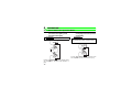
This product is a unit for setting inverter functions (parameters) and has the following features.
· An operation panel can be removed and a parameter unit can be connected.
· Setting such as direct input method with a numeric keypad, operation status indication, and help function are
usable.
· Eight languages can be displayed.
· Parameter setting values of maximum of three inverters can be stored.
The parameter unit screen displays in this instruction manual are examples used with the FR-A700 series.
1
1
1.1
PRE-OPERATION INSTRUCTIONS
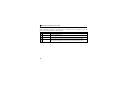
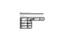
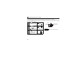
Supporting inverter models
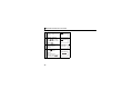
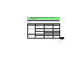
(1) FR-PU07(-01) supporting models
Model
A700 series
F700 series
E700 series
D700 series
500 series
*1
*2
*3
FR-PU07
FR-PU07-01
{
{
{ *2
{ *2
{ *1, *2
×
{ *3
×
×
×
{:supported
× :not supported
Some parameter names displayed are different from those of the FR-PU07.
The FR-PU07 cannot be directly connected to the inverter. To connect to the inverter, the dedicated cable is
required.
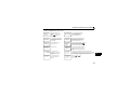
The following functions are available when using FR-PU07-01. To check the compatibility with FR-PU07-01, refer to
the Instruction Manual of the inverter.
Refer to the inverter instruction manual for details of the following functions, changes of the operation key name and
the operation mode indication on LCD. (The functions in this instruction manual are also available with FR-PU07-01.)
•PID display bias/gain setting menu
•Unit selection for the PID parameter/PID monitored items
•PID set point direct setting mode
•Monitor name display on 3-line monitor
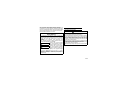
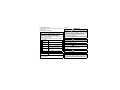
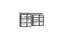
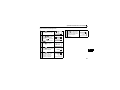
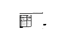
The operation key name and the operation mode indication on LCD of FR-PU07-01 are different with FR-PU07.
(When using FR-PU07-01, assume that the operation key name and the operation mode indication on LCD are
changed as the following table.)
Operation key
FR-PU07-01
FR-PU07
AUTO key,
HAND key
2
EXT key,
PU key
Operation mode indication on LCD
FR-PU07-01
FR-PU07
Indication of AUTO, HAND
READ:List
READ:List
0.00 Hz
0.00 Hz
--- STOP AUTO
--- STOP HAND
Indication of EXT, PU
READ:List
0.00 Hz
--- STOP EXT
READ:List
0.00 Hz
--- STOP PU
Unpacking and Product Confirmation
1.2
Unpacking and Product Confirmation
Take the parameter unit out of the package, check the unit name, and confirm that the product is as you
ordered and intact.
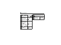
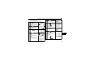
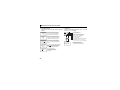
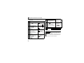
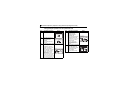
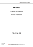
1.2.1
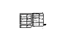
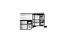
Appearance and parts identification
Unpack the parameter unit, check the name plate on the back, and make sure that the product has not
been damaged before using.
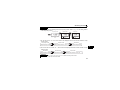
Front
Rear
POWER lamp
Connector for inverter
directly
Lit when the power turns ON.
READ:List
60.00 Hz
STF FWD PU
Connector to the inverter.
Connect directly to PU
connector of the inverter.
(Refer to page 6)
Monitor
Liquid crystal display
(16 characters 4 lines with
backlight)
Interactive parameter setting
Help function
Trouble shooting guidance
Monitor (frequency, current,
power, etc.)
Rating plate
ALARM lamp
1
Connector for PU
cable
Connect using the
connection cable
(FR-CB2
).
Lit to indicate an inverter
alarm occurrence.
(Refer to page 8)
Operation keys
(Refer to page 4)
Bottom
3
Unpacking and Product Confirmation
1.2.2
Explanation of keys
Key
Description
Used to select the parameter setting mode.
Press to select the parameter setting mode.
Used to display the first priority screen.
Used to display the output frequency when making an initial setting.
Operation cancel key.
Used to display the function menu.
A variety of functions can be used on the function menu.
Used to shift to the next item in the setting or monitoring mode.
to
Used to enter a frequency, parameter number or set value.
Used to select the External operation mode.
Used to select the PU operation mode to display the frequency setting screen.
/
· Used to keep on increasing or decreasing the running frequency. Hold down to change the
frequency.
· Press either of these keys on the parameter setting mode screen to change the parameter setting
value sequentially.
· On the selecting screen, these keys are used to move the cursor.
· Hold down
page.
4
and press either of these keys to advance or return the display screen one
Unpacking and Product Confirmation
Key
Description
Forward rotation command key.
Reverse rotation command key.
· Stop command key.
· Used to reset the inverter when a fault occurs.
· Used to write a set value in the setting mode.
· Used as a clear key in the all parameter clear or alarm history clear mode.
· Used as a decimal point when entering numerical value.
· Used as a parameter number read key in the setting mode.
· Used as an item select key on the menu screen such as parameter list or monitoring list.
· Used as an alarm definition display key in the alarm history display mode.
· Used as a command voltage read key in the calibration mode.
1
CAUTION
· Do not use a sharp-pointed tool to push the keys.
· Do not press your fingers against the display.
5
Installation and Removal of FR-PU07
1.3
Installation and Removal of FR-PU07
To ensure safety, install or remove FR-PU07 after switching the power of the inverter OFF.
FR-PU07 cannot be directly installed to the FR-E700, D700 inverter.
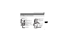
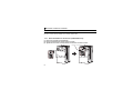
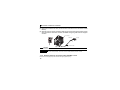
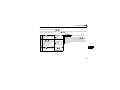
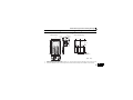
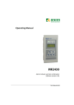
1.3.1
Direct installation to the inverter (A700/F700 series)
(1) Remove the operation panel (FR-DU07).
(2) Insert the parameter unit straight and fit it securely.
(3) Tighten the two screws on the parameter unit to fix the unit to the inverter.
Fixed screw
STF FWD PU
STF FWD PU
6
Installation and Removal of FR-PU07
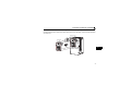
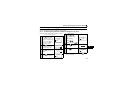
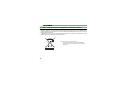
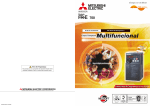
1.3.2
Removal from the inverter (A700/F700 series)
Loosen the fixed screws, hold down the right and left hooks of the FR-PU07, and then pull the parameter
unit toward you.
Press the hooks.
Fixed screw
STF FWD PU
STF FWD PU
1
7
Installation and Removal of FR-PU07
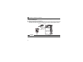
1.3.3
Installation using the connection cable (FR-CB2)
•For the FR-A700/FR-F700
(1) Remove the operation panel (FR-DU07).
(2) Securely insert one end of connection cable into the PU connector of the inverter and the other
end into the connection connector of FR-PU07 along the guides until the stoppers are fixed.
FR-PU07
Stopper
STF FWD PU
Connection cable
CAUTION
Do not connect the connection cable when the front cover is removed.
8
Installation and Removal of FR-PU07
•For FR-E700
(1) Open the PU connector cover.
(2) Securely insert one end of connection cable into the PU connector of the inverter and the other
end into the connection connector of FR-PU07 along the guides until the stoppers are fixed.
Stopper
FR-PU07
PU connector
STF FWD PU
Connection cable
1
Stopper
CAUTION
Do not connect the connection cable when the front cover is removed.
REMARKS
For details of the connection cable (FR-CB2), refer to the connection cable (FR-CB2) instruction manual.
9
Installation and Removal of FR-PU07
•For FR-D700
(1) Remove the inverter front cover. (For the removal of the front cover, refer to the inverter
manual.)
(2) Securely insert one end of connection cable into the PU connector of the inverter and the
other end into the connection connector of FR-PU07 along the guides until the stoppers
are fixed.
PU connector
FR-PU07
Stopper
STF FWD PU
Stopper
Connection cable
CAUTION
Do not connect the connection cable when the front cover is removed.
REMARKS
For details of the connection cable (FR-CB2), refer to the connection cable (FR-CB2) instruction manual.
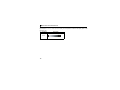
1.3.4
Removal when the connection cable (FR-CB2) is used
Hold down the tab (stopper) at the cable end and gently pull the plug.
10
Parameters to be Checked First
1.4
Parameters to be Checked First
Change the following parameter settings as required.
For the changing procedures, refer to page 23.
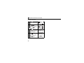
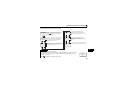
1.4.1
PU display language selection (Pr. 145)
By setting the Pr. 145 PU display language selection value, you can select the language displayed on the
parameter unit.
Pr. 145 Setting
0
1 (initial value)
2
3
4
5
6
7
1.4.2
Display Language
Japanese
English
German
French
Spanish
Italian
Swedish
Finnish
1
PU buzzer control (Pr. 990)
By setting the Pr. 990 PU buzzer control value, you can select to either generate or mute the "beep" which
sounds when you press any of the parameter unit keys.
Pr. 990 Setting
Description
0
1 (initial value)
No buzzer sound
Buzzer sound generated
11
Parameters to be Checked First
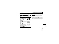
1.4.3
PU contrast adjustment (Pr. 991)
By setting the Pr. 991 PU contrast adjustment value, you can adjust the contrast for the display panel of the
parameter unit.
Pr. 991 Setting
Description
「0」
「63」
「58」
0 to 63
Light
12
Initial value Dark
2
FUNCTIONS
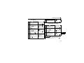
2.1
Monitoring Function
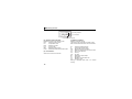
2.1.1
Display overview
(1) Main monitor
READ:List
OL
Hz
120.00
STF
(2) Rotation direction indication
(1) Main monitor
Shows the output frequency, output current, output
voltage, alarm history and other monitor data.
· Using
page 15)
to change to the next screen (Refer to
· Using
to change to the next screen (Refer to
page 49 )
· Using the parameter "PU main display data
selection" (Refer to page 18 )
FWD
PU
(3) Operating status indication
(2) Rotation direction indication
Display the direction (forward rotation/reverse
rotation) of the start command.
STF : Forward rotation
STR : Reverse rotation
--: No command or both STF and STR ON
(3) Operating status indication
Display the running status of the inverter.
STOP : During stop
FWD : During forward rotation
REV : During reverse rotation
JOGf : During Jog forward rotation
JOGr : During Jog reverse rotation
ARAR : At fault occurrence
13
2
Monitoring Function
READ:List
OL
Hz
120.00
STF
FWD
PU
(6) Warning indication
(5) Unit indication
(4) Operating mode indication
(4) Operation mode indication
Displays the status of the operation mode.
EXT
: External operation mode
PU
: PU operation mode
EXTj
: External Jog mode
PUj
: PU Jog mode
NET
: Network operation mode
PU+E : External/PU combined operation mode
(5) Unit indication
Shows the unit of the main monitor.
14
(6) Warning indication
Displays an inverter warning.
The warning type varies with the inverter model.
Refer to the inverter instruction manual for details.
OL
: Overcurrent stall prevention
oL
: Overvoltage stall prevention
RB
: Regenerative brake pre-alarm
TH
: Electronic thermal relay function pre-alarm
ZC
: Zero current detection
PS
: PU stop
FN
: Fan fault
MT
: Maintenance signal output
SL
: Speed limit
CF
: SSCNET communication error
CP
: Parameter copy
Nothing is displayed when there is no inverter
warning.
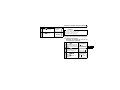
Monitoring Function
2.1.2
Using
"S HIFT"
to change the main monitor
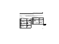
When "0" (initial value) is set in the Pr. 52 DU/PU main display data selection, simply pressing
different monitor screens in sequence.
calls 6
Switch power
ON or press
When output frequency
is the first priority
monitor (Initial setting)
When output current is
the first priority monitor
READ:List
READ:List
0.00 Hz
--- STOP EXT
--- STOP EXT
Output current monitor
0.00Hz
0.00A
0.0V
--- STOP EXT
3-step monitor
When the first priority
monitor is other than
output frequency, output
current and output voltage
0.00 A
Output frequency monitor
First priority monitor and
top two monitors among
output current, output
frequency, and output voltage
are displayed in rows
READ:List
0.0 %
--- STOP EXT
When output voltage is
the first priority monitor
OTHERS
<READ>
Selective monitor
When the first priority
monitor is other than output
frequency, output current
and output voltage
(Example: When electric thermal relay function load
factor is set as the first priority monitor)
READ:List
0.0 V
--- STOP EXT
Output voltage monitor
2
ALARM HISTORY
<READ>
Alarm history monitor
1 UVT 5
2 OC1 6
3
7
4
8
15
Monitoring Function
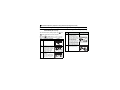
2.1.3
Setting the power-ON monitor (the first priority monitor)
Set the monitor which appears first when power is switched ON or
• When you press
during any monitor screen other than ALARM HISTORY being displayed, that
screen is set as the power-ON screen and will be displayed first.
16
is pressed.
Monitoring Function
2.1.4
Using
"READ"
to change the main monitor
Press
to display the monitoring list while the main monitor is displayed.
Select a monitor from the monitoring list to change the main monitor.
Example: Select the output current peak value monitor. *1 The selected monitor is not set as the first priority
1 Press
.
0.00 A
The parameter unit is in the
monitoring mode.
2
Press
.
The monitoring list appears.
3
Press
/
or
--- STOP PU
1
2
3
4
and press
to shift one
*2
9
10
11
12
Br.Duty %
Therm O/L
Peak I
DC Peak V
Press
. *1
The output current peak is
displayed.
5
Press
Pressing
sets the selected "output current
peak" to be displayed in the first priority monitor
when switched to the monitoring mode from other
operation modes. To give first priority to another
monitor screen, press
with that monitor screen
being displayed. (Refer to page 16)
REMARKS
screen.
4
must be selected again. When you press
to
select the first priority screen, the selected item is
stored in memory.
Frequency
Current
Voltage
Alarm His
to move
the cursor to "Peak I".
Hold down
monitor yet when only
was pressed. Hence,
the selected monitor is erased from memory as
soon as the power is switched OFF or another
operation mode is selected. In this case, the item
READ:List
. *2
The screen in step 4) is set as
the first priority monitor.
READ:List
0.00 A
--- STOP EXT
Subsequently press
to call another
monitor screen.
· The setting can be also made from the function
menu. For details refer to page 43.
· When "Current monitor" or "Power monitor" is selected,
note that any current or power not more than 5% of the
rated inverter current cannot be detected and displayed.
Example:When a small motor is rotated with a largecapacity inverter (a 0.4kW motor is used with a
55kW inverter), the power monitor keeps
displaying 0kW and is inoperative.
17
2
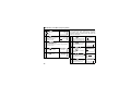
Monitoring Function
2.1.5
Using the parameter to change the monitor (Pr. 52)
To change the third monitor (output voltage monitor), set Pr. 52 DU/PU main display data selection.
(Note that setting "17" (load meter) *2, "18" (Motor excitation current) *1 *2, and "24" (Motor load ratio)
change the output current monitor.
"Output voltage monitor" monitor displays from the first priority monitor using
*1
*2
Cannot be monitored for the FR-F700 series.
Cannot be monitored for the FR-E700, D700 series.
REMARKS
Refer to the instruction manual of each inverter for monitor description.
18
.
Monitoring Function
Factory setting
* The monitor displayed at powering ON is the first priority monitor. Refer to page 16 for the setting method
of the first priority monitor.
First priority monitor
Second monitor
Third monitor
READ:List
READ:List
READ:List
0.00 A
0.00 Hz
0.00 V
--- STOP EXT
--- STOP EXT
--- STOP EXT
(Output frequency monitor)
First
(Output current monitor)
(Output voltage monitor)
1)
Second
2)
Third
1) For the set value of "17, 18, 24", their monitors are displayed at the second monitor instead of output
current monitor.
First priority monitor
Output frequency monitor
Second monitor
Monitor of the set value "17, 18, 24"
Third monitor
Output voltage monitor
2
2) For the set value of "19 to 23, 25·····", their monitors are displayed at the third monitor instead of output
voltage monitor.
First monitor
Output frequency monitor
Second monitor
Output current monitor
Third monitor
Monitor of the set value "19 to 23, 25 ..... "
REMARKS
The setting range of Pr. 52 DU/PU main display data selection differs according to the inverter.
Refer to the inverter instruction manual for details.
19
Frequency Setting
2.2
Frequency Setting
The frequency in PU operation mode and External/PU combined operation mode (Pr. 79 = "3") can be set.
REMARKS
When changing the operation mode from External operation mode to PU operation mode, operation mode can not be
changed if the external starting signal (STF or STR) is ON.
2.2.1
Direct setting
Directly enter a frequency setting using
to
.
• Operation procedure (Changing from 0Hz setting to 60Hz setting)
1
Press
.
The frequency setting screen
appears.
2 Press
and
.
Enter 60Hz. *
3
Press
.
The 60Hz setting is complete.
Freq Set
SET 0.00Hz
0~400Hz
Freq Set
SET 0.00Hz
60.00Hz
0~400Hz
Freq Set
SET 60.00Hz
Completed
*
20
If you entered an incorrect value, press
return to the pre-entry state.
to
Frequency Setting
2.2.2
Step setting
Change frequency continuously using
/
.
You can change the frequency only while you press
/
. Since the frequency changes slowly at first, this setting
can be used for fine adjustment.
1
Press
.
The frequency setting screen
appears.
2
Press
/
You can set any value
between the maximum
frequency (Pr. 1 ) and
minimum frequency (Pr. 2 ).
3
Press
Change of frequency can be made during operation by
0~400Hz
the step setting. However, pressing
to enter
a desired value (60.00Hz).
.
The 60Hz setting is complete.
REMARKS
Freq Set
SET 0.00Hz
Freq Set
SET 0.00Hz
60.00Hz
0~400Hz
/
at
monitor mode may cause actual set frequency to be
higher/lower from the indicated frequency on the
monitor. When performing the step setting at monitor
mode, make sure that output frequency is following the
set frequency.
2
Freq Set
SET 60.00Hz
Completed
21
Frequency Setting
2.2.3
Precautions for frequency setting
1) Pr. 79 Operation mode selection must have been set to switch to the PU operation. (Refer to the inverter
instruction manual for details of Pr. 79 .)
2) In the monitor mode, you cannot make the direct setting (Refer to page 20) to set the running frequency.
Perform the step setting (Refer to page 21) and press
, or press
to display the frequency setting
screen before frequency setting.
Monitor mode
READ:List
30.00 Hz
STF FWD PU
22
Deselect monitor mode
Frequency setting screen
Freq Set
SET 0.00Hz
0~400Hz
Setting and Changing the Parameter Values
2.3
Setting and Changing the Parameter Values
Using the FR-PU07 allows you to read the parameter of inverter or change the set value easily. Refer to
the inverter instruction manual for details of the parameters.
2.3.1
Specifying the parameter number to change the set value
Example: When changing 5s to 180s at the Pr. 8
Deceleration time setting
1
Press
.
(You need not press
when
the parameter unit is already in
the PU operation mode.)
2 Press
.
The parameter unit is in the
parameter setting mode.
Press
.*
.
The present setting appears.
8 Dec.T1
5.0S
180S
0~3600
Or
(2)Step setting
Freq Set
SET 0.00Hz
Press
0~400Hz
.
Display "180" using
6
SETTING MODE
0~9:Ser Pr.NO.
Press
.
The set value is changed.
SETTING MODE
Pr.NO.
8
<READ>
8 Dec.T1
180.0S
2
Press
to display the
next parameter.
9 Set THM
2.55A
0~500
*
8 Dec.T1
5.0S
.
Completed
Select Oper
7
.
Enter the desired parameter
number.
4
Press
Enter the desired value.
The frequency setting screen
appears, and operation mode
changes to PU operation mode.
3 Press
5 (1) Direct setting
If you entered an incorrect value, press
to the pre-entry state.
to return
0~3600
23
Setting and Changing the Parameter Values
2.3.2
Selecting the parameter from functional list to change the set value
Example: When changing 5s to 180s at the Pr. 8
Deceleration time setting
1
Press
.
The frequency setting screen
appears, and operation mode
changes to PU operation mode.
2 Press
.
The parameter unit is in the
parameter setting mode.
3
4
SETTING MODE
0~9:Ser Pr.NO.
Appl.Grp
Pr.List
User List
Param Copy
Press
1
2
3
4
Basic Func
F Command
Acc.Dec
V/F pattern
1
2
3
4
Basic Func
F Command
Acc.Dec
V/F pattern
5 Select a function.
Point the cursor to "Acc.Dec"
using
.
.
7 Select a function.
Using
, point the
cursor to " Accl/Decl T".
8
Select Oper
1
2
3
4
The function list appears.
24
0~400Hz
Press
A function list regarding
acceleration/deceleration is
displayed.
Freq Set
SET 0.00Hz
Select the screen using
and move the cursor to
"Appl.Grp".
.
6
Press
.
A parameter list regarding
acceleration/deceleration
time is displayed.
9
1 Accl/Decl T
2 Accl/Decl P
3 Brake Seq
1 Accl/Decl T
2 Accl/Decl P
3 Brake Seq
7
8
16
20
Acc.T1
Dec.T1
JOG T
Acc/DecF
When moving the cursor to
"Dec.T1" using
and
pressing
, the present set
value is called.
8 Dec.T1
5.0S
0~3600
Setting and Changing the Parameter Values
10 (1) Direct setting
Press
.*
Enter the desired value.
8 Dec.T1
5.0S
180S
0~3600
Or
(2)Step setting
Press
.
Display "180" using
11
Press
.
The set value is changed.
.
8 Dec.T1
180.0S
Completed
12
*
Press
to display the next parameter.
If
is pressed when an incorrect setting value is
input, the display returns to the list display "8".
2
25
Setting and Changing the Parameter Values
2.3.3
Selecting the parameter from parameter list to change the set value
Example: When changing 5s to 180s at the Pr. 8
Deceleration time setting
1
Press
The frequency setting screen
appears, and operation mode
changes to PU operation mode.
.
The parameter unit is in the
parameter setting mode.
3
Change the screen using
.
4 Select a parameter list.
Using
, point the
cursor to "Pr.List".
5
Press
.
Select the parameter list.
The list of the parameters can
be read appears.
26
When moving the cursor
using
.
2 Press
6 Select the parameter.
Freq Set
SET 0.00Hz
at "Dec.T1", the present
set value is called.
0~400Hz
Press
1
2
3
4
Appl.Grp
Pr.List
User List
Param Copy
0
1
2
3
Trq.Bst1
Max.F1
Min.F1
VFbaseF1
.*
Enter the desired value.
8 Dec.T1
5.0S
180S
0~3600
Or
(2)Step setting
Select Oper
Appl.Grp
Pr.List
User List
Param Copy
0~3600
7 (1) Direct setting
SETTING MODE
0~9:Ser Pr.NO.
1
2
3
4
8 Dec.T1
5.0S
and pressing
Press
.
Display "180" using
8
Press
.
The set value is changed.
.
8 Dec.T1
180.0S
Completed
9
*
Press
to display the next parameter.
If
is pressed when an incorrect setting value is
input, the display returns to the list display "5".
Setting and Changing the Parameter Values
2.3.4
Selecting the parameter from User List to change the set value
If a parameter is registered to User List, the parameter can be read from User List and changed. (For
registering the user group, refer to page 29 .)
Example: When changing 5s to 180s at the Pr. 8
6 Select the parameter.
Deceleration time setting
When moving the cursor
8 Dec.T1
1
Press
using
.
The frequency setting screen
appears, and operation mode
changes to PU operation mode.
2 Press
.
The parameter unit is in the
parameter setting mode.
3
Change the screen using
.
4 Select a User List.
Using
, point the
cursor to "User List".
5
Press
.
The list of the parameters
registered to User List
appears.
Freq Set
SET 0.00Hz
at "Dec.T1", the present
set value is called.
0~400Hz
Press
1
2
3
4
Appl.Grp
Pr.List
User List
Param Copy
8 Dec.T1
5.0S
180S
0~3600
Or
(2) Step setting
Press
.
Display "180" using
8
Press
.
The set value is changed.
2
.
8 Dec.T1
180.0S
Completed
9
8 Dec.T1
75 RES Mode
.*
Enter the desired value.
Select Oper
Appl.Grp
Pr.List
User List
Param Copy
0~3600
7 (1) Direct setting
SETTING MODE
0~9:Ser Pr.NO.
1
2
3
4
5.0S
and pressing
*
Press
to display the next parameter.
If
is pressed when an incorrect setting value is
input, the display returns to the list display "5".
27
Setting and Changing the Parameter Values
2.3.5
Precautions for setting write
· Perform parameter setting change during an inverter stop basically in the PU operation mode or
combined operation mode. The parameter setting can not be changed in the External operation mode or
during inverter operation. (Read is performed independently of the operation mode.) Note that some
parameters can be written even in the External operation mode or during operation. Therefore, refer to
the inverter manual.
· As Pr. 77 Parameter write selection = "0" in the initial setting, parameter can be written only during an
inverter stop. (Read is allowed even during operation.) Note that some parameters can be written
always. Refer to the inverter manual for details of Pr. 77.
· In addition to the above case, setting write cannot be performed when:
1) The parameter number selected does not exist in the parameter list; or
2) The value entered is outside the setting range.
· When write cannot be performed and the "Setting Err." appears, press
and make setting once more.
(Example: For Pr. 7 Acceleration time )
7 Acc.T1
Setting Error
20000S
<ESC>
28
User Group Function
2.4
User Group Function
· User group function is a function to display only parameters necessary for setting.
· Among all parameters, maximum 16 parameters can be registered to the user group. When "1" is set in
Pr. 160, only parameters registered in the user group can be accessed for reading and writing. (The
parameters not registered to the user group cannot be read.)
REMARKS
FR-D700 does not have the user group function.
2
29
User Group Function
2.4.1
Registering the parameters to user group
1 Press
.
The parameter unit is in the
parameter setting mode.
SETTING MODE
0~9:Ser Pr.NO.
Select Oper
2 Read the parameters.
Enter the parameter
number to be registered to
the user group with the
number keys and press
to read the parameter
setting.
8 Dec.T1
5.0S
0~3600
3 Set the parameters.
When changing the set
value, enter a new value
with the number keys and
press
to write.
When not changing the
8 Dec.T1
5.0S
180S
0~3600
setting value, press
to
display the setting completion
screen.
4
Press
.
The selecting screen
appears.
30
Add Pr.
User List
Yes:Add
No :Cancel
5 Register.
When moving the cursor to "YES" and pressing
, the registration is executed.
6 The parameter setting
screen appears. To
continue parameter
registration, repeat the
operation from step 2.
SETTING MODE
0~9:Ser Pr.NO.
Select Oper
User Group Function
2.4.2
Deleting the parameters from
user group
1 Press
.
The parameter unit is in the
parameter setting mode.
SETTING MODE
0~9:Ser Pr.NO.
Select Oper
2 Select "User List".
Using
/
, point the
cursor to "3 User List" and
press
.
1
2
3
4
Appl.Grp
Pr.List
User List
Param Copy
Using
/
, point the
cursor to the parameter to be
deleted and press
1
2
3
7
Max.F1
Min.F1
VFbaseF1
Acc.T1
4 Delete.
pressing
deleted.
, the parameter is
2.4.3
1
2
7
8
Max.F1
Min.F1
Acc.T1
Dec.T1
Confirming the parameters
registered to user group
1 Press
.
The parameter unit is in the
parameter setting mode.
Using
/
press
.
, point the
cursor to "3 User List" and
3 Read the parameter.
.
The screen of delete
confirmation appears. When
pointing the cursor to "Yes" and
parameter, repeat the
operation from step 3.
SETTING MODE
0~9:Ser Pr.NO.
Select Oper
2 Select "User List".
3 Select the parameter to be
deleted.
5 To continue deleting
Delete Pr.
User List
Yes:Delete
No :Cancel
You can confirm the
parameters registered to
the user group.
1
2
3
4
Appl.Grp
Pr.List
User List
Param Copy
1
2
3
7
Max.F1
Min.F1
VFbaseF1
Acc.T1
2
REMARKS
If the parameter is not registered to the user group,
"User List Setting Err." will be displayed. Press
return to the screen of step 1.
to
31
Calibration of the Meter (Frequency Meter)
2.5
Calibration of the Meter (Frequency Meter)
The functions vary with the inverter. (Refer to the inverter instruction manual for details of the parameters.)
2.5.1
Calibration of the FM terminal
3
Parameter
Pr. 900 FM terminal calibration
Pr. 54 FM terminal function selection
Pr. 55 Frequency monitoring reference
press
This section provides the way to calibrate the fullscale of meter connected to terminal FM using the
parameter unit.
• Calibrating the meter at the running frequency of
60Hz
1
.
The frequency setting screen
appears, and operation mode
changes to PU operation mode.
2 Press
.
The parameter unit is in the
parameter setting mode.
32
4
Enter
and press
60Hz is set.
Press
.
Forward rotation is performed
at 60Hz. You need not
connect the motor.
0~400Hz
6
Select Oper
.
.
Freq Set
SET 0.00Hz
SETTING MODE
0~9:Ser Pr.NO.
and
The preset frequency is
displayed.
5
Press
Enter
Using
/
, adjust
the meter pointer to a
predetermined position.
The meter pointer moves. (It
takes a long time before the
pointer moves.)
900 FM Tune
Run Inverter
0.00Hz
PU
900 FM Tune
Run Inverter
60Hz
PU
900 FM Tune
MntrF 60.00Hz
<WRITE>PU
Calibration of the Meter (Frequency Meter)
7
Press
.
Calibration is complete.
8 Press
to return to the
main monitor screen.
900 FM Tune
Completed
<MONITOR>
READ:List
60.00 Hz
STF FWD PU
2.5.2
Calibration of the AM terminal
Parameter
Pr. 901 AM terminal calibration
Pr. 158 AM terminal function selection
Pr. 55 Frequency monitoring reference
Pr. 56 Current monitoring reference
This section provides a way to calibrate the meter
connected to terminal AM using the parameter unit.
(1) Calibration procedure 1
(Example: To calibrate the meter at the
running frequency of 60Hz)
1
Press
.
The frequency setting screen
appears, and operation mode
changes to PU operation mode.
2 Press
.
The parameter unit is in the
parameter setting mode.
3
Enter
press
Freq Set
SET 0.00Hz
0~400Hz
2
SETTING MODE
0~9:Ser Pr.NO.
Select Oper
and
.
The preset frequency is
displayed.
901 AM Tune
Run Inverter
0.00Hz
PU
33
Calibration of the Meter (Frequency Meter)
4
Enter
and press
.
60Hz is set.
5
Press
.
Forward rotation is performed
at 60Hz. You need not
connect the motor.
6
Using
/
(2) When calibrating output current
901 AM Tune
Run Inverter
60Hz
PU
901 AM Tune
MntrF 60.00Hz
For the output current or another item, which does
not easily point 100% value during operation,
adjust the reference voltage output, then select the
item to be displayed.
1
2 Press
predetermined position.
The meter pointer moves. (It takes a long time before
the pointer moves.)
7
Press
.
Calibration is complete.
8
Press
to return to the
main monitor screen.
READ:List
STF FWD PU
.
3
Enter
press
0~400Hz
Select Oper
and
158 AM set
1
.
The present Pr. 158 setting
appears.
4
Enter
and press
The setting of reference
voltage output is complete.
5 Press
.
The parameter unit is in the
parameter setting mode.
34
Freq Set
SET 0.00Hz
SETTING MODE
0~9:Ser Pr.NO.
The parameter unit is in the
parameter setting mode.
901 AM Tune
Completed
<MONITOR>
60.00 Hz
.
The frequency setting screen
appears, and operation mode
changes to PU operation mode.
<WRITE>PU
, adjust the meter pointer to a
Press
.
158 AM set
21
Completed
SETTING MODE
0~9:Ser Pr.NO.
Select Oper
Calibration of the Meter (Frequency Meter)
6
Enter
press
.
The present Pr. 901 setting
appears.
7
Enter
The setting of maximum
running frequency is
complete.
Press
Using
901 AM Tune
Run Inverter
60Hz
PU
/
901 AM Tune
MntrF
1000
<WRITE>PU
.
SETTING MODE
0~9:Ser Pr.NO.
The parameter unit is in the
parameter setting mode.
11
Enter
press
.
Forward rotation is performed
at 60Hz.
You need not connect the
motor to make adjustment.
9
901 AM Tune
Run Inverter
0.00Hz
PU
and press
.
8
10 Press
and
Select Oper
and
158 AM set
21
.
The present Pr. 158 setting
appears.
12
Enter
and press
.
The setting of output current
is complete.
The output current for 10VDC
is the setting value of Pr. 56
Current monitoring reference
(initial value: rated inverter
current).
158 AM set
2
Completed
2
, adjust the
voltage across terminals
AM-5 and press
.
Setting is complete.
The output voltage displayed
is the value at 100% output.
This voltage is not stored if
you do not press
901 AM Tune
Completed
<MONITOR>
.
35
Adjustment of the Frequency Setting Signals "Bias" and "Gain"
2.6
Adjustment of the Frequency Setting Signals "Bias" and "Gain"
The functions vary with the inverter model. (Refer to the inverter instruction manual for details of the
functions.)
2.6.1
Adjustment procedure
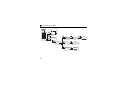
There are three ways to adjust the bias and gain of the frequency setting voltage (current).
(1) Adjust only the bias and gain frequencies and not adjust the voltage (current) (Refer to page 37)
(2) Adjust any point by applying a voltage across terminals 2-5 (starting a current across terminals 4-5)
(Refer to page 39)
(3) Adjust any point without a voltage being applied across terminals 2-5 (without a current being applied
across terminals 4-5) (Page 41)
Parameter
Pr. 902 Terminal 2 frequency setting bias frequency
Pr. 903 Terminal 2 frequency setting gain
Pr. 904 Terminal 4 frequency setting bias frequency
Pr. 905 Terminal 4 frequency setting gain
36
Adjustment of the Frequency Setting Signals "Bias" and "Gain"
(1) Adjust only the bias and gain frequencies and
not adjust the voltage
• Setting of the frequency setting voltage bias
1
Press
.
The frequency setting screen
appears, and operation mode
changes to PU operation mode.
2 Press
.
The parameter unit is in the
parameter setting mode.
3
Enter
press
Enter
Press
.
The bias frequency is set at
10Hz.
f
0~400Hz
0
SETTING MODE
0~9:Ser Pr.NO.
Select Oper
902 Ext2bias
10.00Hz
10Hz
V
Completed
If the voltage is being applied
across terminals 2- 5 at this
time, the bias setting is as
shown above.
and
.
The present Pr. 902 setting
appears.
4
Freq Set
SET 0.00Hz
5
.
Voltage need not be applied
across terminals 2-5.
902 Ext2bias
0.00Hz
Set<WRITE>
Ext<READ>
2
902 Ext2bias
10Hz
Set<WRITE>
37
Adjustment of the Frequency Setting Signals "Bias" and "Gain"
• Setting
of the frequency setting voltage gain
6 Press
.
The present setting appears.
7
Enter
.
Voltage need not be applied
across terminals 2-5.
8
Press
903 Ext2gain
60.00Hz
Set<WRITE>
Ext<READ>
903 Ext2gain
50Hz
Set<WRITE>
.
The bias frequency is set at
50Hz.
At this time, set the gain on
the assumption that the 5V
(10V) in the inverter is the set
voltage.
903 Ext2gain
50.00Hz
Completed
f
50Hz
10Hz
0
5V
(10V)
V
The adjustment of the frequency setting voltage
bias and gain is complete.
38
REMARKS
1
2
The current input (Pr. 904) can also be adjusted
using a similar procedure.
The Pr. 903 Terminal 2 frequency setting gain remains
unchanged if the Pr. 20 Acceleration/deceleration
reference frequency setting is changed.
Adjustment of the Frequency Setting Signals "Bias" and "Gain"
(2) Adjust any point by application of voltage to
across terminals 2-5
• Setting of the frequency setting voltage bias
1
Press
.
The frequency setting screen
appears, and operation mode
changes to PU operation mode.
2 Press
.
The parameter unit is in the
parameter setting mode.
3
4
Enter
.
Press
twice.
The present Pr. 902 setting
appears.
When the set voltage is
changed, the % value also
changes.
This example assumes that a
1V voltage is applied.
The value selected in Pr. 73
(5V in this example) is 100%.
5
.
Set the bias frequency at
10Hz.
f
Freq Set
SET 0.00Hz
10Hz
0 1V
0~400Hz
6
SETTING MODE
0~9:Ser Pr.NO.
Press
7
SETTING MODE
Pr.No.
902
<READ>
8
1)
2)
1) The previous
setting is
displayed.
2) The present set
voltage across
terminals 2-5 is
displayed in %.
) moves to the
Apply a 0V voltage.
In this example, 0V is applied
as 10Hz is set for 0V.
(Indicated % on the right
changes.)
Press
902 Ext2bias
10.00Hz
0.5%
EXT
20.0%
V
.
The cursor (
set voltage.
Select Oper
902 Ext2bias
5.00Hz
0.5%
Ext
20.0%
Enter
902 Ext2bias
10.00Hz
0.5%
Ext - 0.2%
902 Ext2bias
10.00Hz
0.5%
Ext - 0.2%
2
.
The bias frequency is set at
10Hz for 0V input.
Setting is completed as
shown below:
f
10Hz
0
V
902 Ext2bias
10.00Hz
- 0.2%
Completed
0.0% of analog input
value may not be
displayed in some
cases.
39
Adjustment of the Frequency Setting Signals "Bias" and "Gain"
•
Setting of the frequency setting voltage gain
9
Press
, then
.
The present Pr. 903 setting
appears.
When the set voltage is
changed, the % value also
changes.
The value selected in Pr. 73
(5V in this example) is 100%.
10
11
Enter
Press
The cursor (
set voltage.
12
40
.
.
) moves to the
Apply a 5V voltage.
In this example, 5V is applied
to set 50Hz for 5V input.
903 Ext2gain
60.00Hz
97.1%
Ext
80.0%
13
903 Ext2gain
50.00Hz
97.1%
Ext
80.0%
903 Ext2gain
50.00Hz
97.1%
Ext
80.0%
.
The gain frequency is set at
50Hz for 5V input.
Setting is completed as
shown below:
1)
2)
1) The previous
setting is
displayed.
2) The present set
voltage across
terminals 2-5 is
displayed in %.
903 Ext2gain
50Hz
97.1%
Ext
80.0%
Press
f
50Hz
The value displayed
may not be just
100.0% in some
cases.
10Hz
0
(0%)
903 Ext2gain
50.00Hz
99.6%
Completed
5V
(100%)
V
The adjustment of the frequency setting voltage
bias and gain is complete.
REMARKS
1
2
3
The current input (Pr. 904, Pr. 905 ) can also be
adjusted using a similar procedure.
The Pr. 903 Terminal 2 frequency setting gain remains
unchanged even if the Pr. 20 Acceleration/
deceleration reference frequency setting is changed.
A narrow calibration (command) value set using Pr.
902 and Pr. 903 (Pr. 904 and Pr. 905) will result in "Incr
I/P" and disable write.
Adjustment of the Frequency Setting Signals "Bias" and "Gain"
(3) Adjust any point without application of voltage
to across terminals 2-5
• Setting of the frequency setting voltage bias
1
Press
.
The frequency setting screen
appears, and operation mode
changes to PU operation mode.
2 Press
.
The parameter unit is in the
parameter setting mode.
3
4
5
.
Set the bias frequency at
10Hz.
6
Freq Set
SET 0.00Hz
Enter
Press
.
The cursor ( ) moves to the
set voltage.
Voltage need not be applied
across terminals 2-5.
0~400Hz
SETTING MODE
0~9:Ser Pr.NO.
7
Select Oper
Enter
.
Press
.
twice.
The present Pr. 902 setting
appears.
When the set voltage is
changed, the % value also
changes.
The value selected in Pr. 73
(5V in this example) is 100%.
SETTING MODE
Pr.No.
902
<READ>
902 Ext2bias
5.00Hz
0.5%
Ext -0.5%
8
1)
2)
1) The previous
setting is
displayed.
2) The present set
voltage across
terminals 2-5 is
displayed in %.
Press
902 Ext2bias
10.00Hz
-0.5%
Ext -0.5%
902 Ext2bias
10.00Hz
- 0%
Ext -0.5%
Input 0V to set bias.
Enter
902 Ext2bias
10Hz
-0.5%
Ext -0.5%
.
The bias frequency is set at
10Hz.
Setting is completed as
shown below:
f
2
902 Ext2bias
10.00Hz
0.0%
Completed
10Hz
0
V
41
Adjustment of the Frequency Setting Signals "Bias" and "Gain"
• Setting of the frequency setting voltage gain
9
Press
, then
.
The present Pr. 903 setting
value appears.
When the set voltage is
changed, the % value also
changes.
The value selected in Pr. 73
(5V in this example) is 100%.
10
Enter
.
Set the gain frequency at
50Hz.
11
1)
2)
f
50Hz
10Hz
0
(0%)
5V
(100%)
903 Ext2gain
50.00Hz
100.0%
Completed
V
The adjustment of the frequency setting voltage
bias and gain is complete.
1
.
Enter
.
Input 5V to set gain.
42
.
The gain frequency is set at
50Hz.
Setting is completed as
shown below:
1) The previous
setting is
displayed.
2) The present set
voltage across
terminals 2-5 is
displayed in %.
903 Ext2gain
50Hz
97.1%
Ext
80.0%
Press
REMARKS
Press
The cursor ( ) moves to the
set voltage.
Voltage need not be applied
across terminals 2-5.
12
903 Ext2gain
60.00Hz
97.1%
Ext
80.0%
13
903 Ext2gain
50.00Hz
97.1%
Ext
80.0%
2
3
903 Ext2gain
50.00Hz
100.0%
Ext
80.0%
The current input (Pr. 904, Pr. 905) can also be
adjusted using a similar procedure.
The Pr. 903 Terminal 2 frequency setting gain remains
unchanged even if the Pr. 20 Acceleration/
deceleration reference frequency setting is changed.
A narrow calibration (command) value set using Pr.
902 and Pr. 903 (Pr. 904 and Pr. 905) will result in "Incr
I/P" and disable write.
3
FUNCTION MENU
3.1
Overview of Function Menu
Press
in any operation mode to call the function menu, on which you can perform various functions.
Hold down
and press
to shift one screen.
Menu screen page 1
1
2
3
4
Press any of the
3.1.1
Menu screen page 2
MONITOR
PU Oper
Pr.list
Pr.Clear
5
6
7
8
+
,
,
Alarm Hist
AlarmClear
INV.Reset
T/Shooting
and
Menu screen page 3
+
9
10
11
12
S/W
Selectop
Option
FRCpy set
keys to switch to the corresponding mode.
Function menu
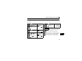
Function Menu
Description
Refer To
Page
1. MONITOR
The monitor list appears, and you can change from one monitor to another and set
the first priority monitor.
49
2. PU Oper
You can select the PU operation mode via direct input (direct setting with the number
keys) or select the Jog operation mode from the PU, and displays how to operate the
keys.
50
3. Pr.List
The parameter menu appears, and you can perform "parameter setting", "list
display", "parameter change list display" and "initial value list display".
52
4. Pr.Clear
The parameter clear menu appears, and you can perform "parameter clear" and "all
clear".
55
3
43
Overview of Function Menu
Function Menu
5. Alarm Hist
6. AlarmClear
7. Inv.Reset
Description
This function displays history of past eight faults (alarms).
This function clears all the fault (alarm) history.
This function resets the inverter.
8. T/Shooting
The inverter displays the cause of mismatch between inverter operation and control/
setting or the cause of an inverter fault.
9. S/W
This function displays the software control number of the inverter.
10. Selectop
This function displays the signals assigned to the I/O terminals of the control circuit
and the ON/OFF states of the signals.
11. Option
12. FRCpy set
This function displays the option fitting states of the option connectors 1 to 3.
The function can perform the "parameter copy" (read, write, verification).
REMARKS
The functions vary with the inverter model and may be invalid for some inverters.
44
Refer To
Page
57
58
59
59
64
65
66
Overview of Function Menu
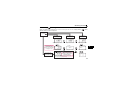
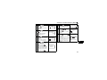
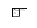
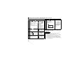
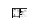
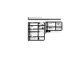
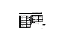
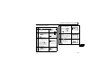
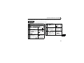
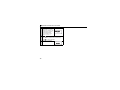
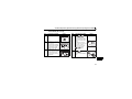
3.1.2
Function menu transition
1 MONITOR
2 PU Oper
3
4
5
6
7
8
9
10
11
12
1
2
3
4
5
6
7
8
9
10
11
12
13
14
15
16
Frequency
Current
Voltage
Alarm His
F Command
RPM
Shaft Trq
DC Link
Br.Duty %
Therm O/L
Peak I
DC Peak V
I/P Power
O/P Power
I/P Signal
O/P Signal
1 PU:Directly
2 JOG:Jogging
*1
*2
*3
Frequency [Hz]
Current [A]
Voltage [V]
Fault description * The latest 8 faults are displayed
Frequency setting (shows the frequency already set)[Hz]
Running speed (shows the motor speed or moving speed)[r] *1
Motor torque (torque produced by the motor) [%] *2
Converter output voltage(DC voltage in converter output) [V]
Regenerative brake duty [%] *3
Electronic thermal relay function load factor [%]
Output current peak [A]
Converter output voltage peak (maximum value of converter output voltage) [V]
Input power (input side power amount currently used) [kW] *1
Output power (output side power amount currently used) [kW]
Input signal (ON-OFF states of STF, STR, etc.) * ON
OFF
Output signal (ON-OFF states of RUN, FU, etc.) * ON
OFF
Operation in PU operation mode at running frequency set by numeric keys.
PU Jog operation mode
3
Cannot be monitored for the FR-E700 and FR-D700 series.
Cannot be monitored for the FR-F700 and FR-D700 series.
Can be monitored for the FR-F700 series with the 75K or higher.
45
Overview of Function Menu
1
2
3
4
1
2
3
4
5
6
7
8
9
10
11
12
Setting Mode
Pr.List
Set Pr.List
Def.Pr.List
Select Oper
0
1
2
3
Pr.List
Pr.Clear
Alarm His
AlarmClear
Trq Bst1
Max.F1
Min.F1
VFbaseF1
SET Pr.LIST
15 JOG F 15.00
79 Oper
1
125 2Freq 50.00
DEF.Pr.LIST
0 Trq B
6.0
1 Max.F 120.00
2 Min.F
0.00
1 Clear Pr.
2 Clear All
1
2
3
4
OHT
SER
OV2
OV2
5
6
7
8
OV2
0V3
OV3
OV3
ALARM CLEAR
Exec<WRITE>
Cancel<ESC>
46
SETTING MODE
0~9:Ser Pr.No.
1
2
3
4
Appl.Grp
Pr.List
User List
Param Copy
0 Trq Bst1
6.0%
0~30
15 JOG F
15.00Hz
0~400
0 Trq Bst1
6.0%
0~30
Clear Pr.
Exec<WRITE>
Cancel<ESC>
Clear Pr.
Clear All Pr.
Exec<WRITE>
Cancel<ESC>
Clear All Pr.
* The latest 8 faults are displayed.
ALARM CLEAR
Completed
Completed
Completed
Overview of Function Menu
INV.RESET
Exec<WRITE>
Cancel<ESC>
[Estimated cause]
1
2
3
4
5
6
7 INV.Reset
8 T/Shooting
9 S/W
10
11
12
1
2
3
4
M.Not Run
M.Spd Error
M.A/Dec Err
M.Curr.High
M.NOT RUNNING
NO I/P Power
or Phase Loss
INV.Output
0.00Hz
0.00A
0.0V
<SHIFT>
Set
5.0S
0 60.00Hz
Set
5.0S
60.00Hz 0
INV.Output
0.00Hz
0.00A
0.0V
<SHIFT>
V/f Setting
Error?
See Pr.3,14,
19,47,113
Stll Pv.ON?
Set Too Low?
Load Too Big?
Pr.22 Error?
Low Impedance
Motor?
Reduce TrqBst
Pr.0,46,112
<S/W>
7889*
3
47
Overview of Function Menu
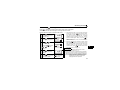
Settings of Pr. 178 to
Pr. 196 are displayed.
Terminal Name
1
2
3
4
5
6
7
8
9
10 Selectop
11 Option
12 PRCpy set
RL
RM
RH
RT
:
:
:
:
ON
OFF
0
1
2
3
<option>
OP1: ---OP2: ---OP3: A7NC
1 Copy area 1
2 Copy area 2
3 Copy area 3
Copy area 1
1 Read VFD
2 Write VFD
3 Verifing
48
Name:000
:Select Char
READ:Decide Char
WRITE:DecideName
000
Overwrite area 1
WRITE:Executing
ESC:Cancel
000
Area 1 to VFD
WRITE:Executing
ESC:Cancel
Param Copy
Writing
Completed
Please Reset
000
Verify Area 1
WRITE:Executing
ESC:Cancel
Param Copy
Verifying
Completed
Param Copy
Reading
Completed
Operation Procedures for Functions
3.2
Operation Procedures for Functions
3.2.1
Monitor function
The monitoring list appears and you can change from one monitor screen to another and set the first
priority screen.
1 Press
5
.
The function menu is called.
2 Make sure that the
cursor is located at "1
MONITOR".
1
2
3
4
MONITOR
PU Oper
Pr.List
Pr.Clear
If not, move the cursor with
/
3
.
The monitor screen selected
by the cursor appears.
Press
to give the first
priority to this monitor screen.
READ:List
0.00 A
--- STOP PU
REMARKS
.
· The monitoring list can be called only with pressing
Press
.
The monitoring list is called.
4
Press
Press
or
/
Frequency
Current
Voltage
Alarm His
1
2
3
4
Frequency
Current
Voltage
Alarm His
to
move the cursor to the
desired item.
Hold down
1
2
3
4
and press
in the monitoring mode. (Refer to page 17)
· "4 Alarm His" can not be set to the first priority
monitor.
· Some monitoring items are not displayed depending
on the connected inverter. To check the available
monitoring items, refer to the setting range of Pr.52
DU/PU main display data selection of the inverter.
to shift one screen.
49
3
Operation Procedures for Functions
3.2.2
Selection of PU operation (direct input)
You can select the PU operation mode to set PU operation frequency.
1 Press
.
The function menu is called.
2
Using
, move the cursor
to "2 PU Oper".
3
Press
1
2
3
4
MONITOR
PU Oper
Pr.List
Pr.Clear
1
2
3
4
MONITOR
PU Oper
Pr.List
Pr.Clear
The menu on the right
appears.
is located at "1 PU:
Directly".
5
Press
50
and press
SET
.
The frequency setting is
complete.
7
Press
· Press
time.
.
.
The PU operation mode is
selected and the frequency
setting screen appears.
to
/
to perform
Freq Set
60.00Hz
Completed
READ:List
60.00 Hz
STF FWD PU
REMARKS
1 PU:Directly
2 JOG:Jogging
If not, move the cursor with
/
using
forward or reverse rotation
with the set frequency.
.
4 Make sure that the cursor
6 Enter the set frequency
SET
Freq Set
0.00Hz
0~400Hz
to call the frequency setting screen any
Operation Procedures for Functions
3.2.3
Selection of the PU Jog operation mode
You can select the PU Jog operation mode to set PU jog frequency.
1 Press
.
The function menu is called.
2
Using
, move the cursor
to "2 PU Oper".
3
Press
.
The menu on the right
appears.
4
Using
, move the cursor
to "2 JOG: Jogging".
5
Press
6 Enter the set frequency
1
2
3
4
1
2
3
4
MONITOR
PU Oper
Pr.List
Pr.Clear
MONITOR
PU Oper
Pr.List
Pr.Clear
1 PU:Directly
2 JOG:Jogging
to
and press
PU/JOG
5.00Hz
SET
.
Completed
The PU Jog frequency setting
is complete.
7
Hold down
/
to
READ:List
perform forward or reverse
rotation with the PU Jog set
frequency.
5.00
Hz
STR JOGr PUj
REMARKS
1 PU:Directly
2 JOG:Jogging
· Press
to call the PU Jog frequency setting
screen any time after pressing
.
The PU Jog operation mode
is selected, and the frequency
setting screen appears.
using
.
3
PU/JOG
0.00Hz
SET
0~400Hz
51
Operation Procedures for Functions
3.2.4
Parameters
When selecting the parameter on the function menu, the parameter menu is displayed, and you can
perform the following operations for the parameters.
Display
1 Setting Mode
2 Pr. List
3 Set Pr. List
4 Def.Pr. List
52
Description
Switches to the parameter setting mode to read and write the parameter setting.
Displays the parameters list.
You can select the parameter from the list to read and write the parameter setting.
Lists the parameters whose setting is changed from initial value.
You can select the parameter from the list to read and write the parameter setting.
Displays the parameters and initial value list.
You can select the parameter from the list to read and write the parameter setting.
Operation Procedures for Functions
(1) "1 Setting Mode"
1 Press
.
The function menu is called.
2
Using
, move the
cursor to "3 Pr. List".
3
Press
.
The parameter menu
appears.
4
Press
2
1
2
3
4
MONITOR
PU Oper
Pr.List
Pr.Clear
1
2
3
4
MONITOR
PU Oper
Pr.List
Pr.Clear
1
2
3
4
Setting Mode
Pr.List
Set Pr.List
Def.Pr.List
SETTING MODE
0~9:Ser Pr.NO.
Select Oper
(2) "2 Pr.List"
1 Call the parameter menu
similarly to above steps 1
to 3.
1
2
3
4
Setting Mode
Pr.List
Set Pr.List
Def.Pr.List
, move the
cursor to "2 Pr. List".
3
Press
1
2
3
4
Setting Mode
Pr.List
Set Pr.List
Def.Pr.List
0
1
2
3
Trq Bst1
Max.F1
Min.F1
VFbaseF1
.
The parameter menu
appears.
4
Press
/
to move
the cursor to the desired
parameter.
Press
and
together to shift to the next
page.
.
The parameter unit switches
to the setting mode.
Refer to page 23 to set the
parameters.
Using
5
Press
.
The parameter indicated by
the cursor is read, and the
parameter unit is in the
parameter setting mode.
Refer to page 23 to set the
parameters.
Press
0 Trq Bst1
6.0%
3
0~30
to move to the next parameter.
53
Operation Procedures for Functions
(3) Display of "3 Set Pr.List"
1 Call the parameter menu
2
similarly to steps 1 to 3 of
page 53.
1
2
3
4
Setting Mode
Pr.List
Set Pr.List
Def.Pr.List
Using
1
2
3
4
Setting Mode
Pr.List
Set Pr.List
Def.Pr.List
/
, move the
cursor to "3 Set Pr. List".
3
Press
.
The change list appears.
When the parameter has
been changed from the initial
value, the new value is
displayed.
4
Press
1 Call the parameter menu
2
3
0~120
1
2
3
4
Setting Mode
Pr.List
Set Pr.List
Def.Pr.List
Using
1
2
3
4
Setting Mode
Pr.List
Set Pr.List
Def.Pr.List
/
, move the
Press
.
The initial value list appears.
4
1 Max.F1
0.00Hz
similarly to steps 1 to 3 of
page 53.
cursor to "4 Def. Pr. List".
SET Pr.LIST
1 Max.F1 0.00
18 Max.F2 0.00
125 2Freq 50.00
.
The parameter indicated by
the cursor is read, and the
parameter unit is in the
parameter setting mode.
Refer to page 23 to set the
parameters.
54
(4) Display of "4 Def.Pr.List"
The initial values of parameters are displayed.
Press
DEF.Pr.LIST
0 Trq B
6.0
1 Max.F 120.00
2 Min.F
0.00
.
The parameter indicated by
the cursor is read, and the
parameter unit is in the
parameter setting mode.
Refer to page 23 to set the
parameters.
0 Trq Bst1
6.0%
0~30
Operation Procedures for Functions
3.2.5
Parameter clear
You can perform the "parameter clear" and "all parameter clear".
Switch to the PU operation mode before performing any operation.
• Clear Pr. .......................... Returns (initializes) the parameters to the factory settings with the exception of
the some parameters (Pr. 75 and calibration values in Pr. 900 to Pr. 905 ).
• Clear All........................... Initializes all parameters with the exception of Pr. 75.
(1) Parameter clear
1 Press
.
The function menu is called.
2
Using
/
, move the
cursor to "4 Pr. Clear".
3
Press
.
The parameter menu
appears.
5
1
2
3
4
1
2
3
4
MONITOR
PU Oper
Pr.List
Pr.Clear
MONITOR
PU Oper
Pr.List
Pr.Clear
1 Clear Pr.
2 Clear All
6
"Clear Pr." is selected, and
the confirmation screen for
clearing execution is
displayed.
Press
Clear Pr.
Exec<WRITE>
Cancel<ESC>
.
The parameters are
initialized.
When canceling the
Clear Pr.
COmpleted
initialization, press
on
the confirmation screen.
3
4 Select the "Clear Pr.".
/
, move the
cursor to "1" and press the
Using
1 Clear Pr.
2 Clear All
.
55
Operation Procedures for Functions
(2) All parameter clear
1 Call the parameter menu
similarly to steps 1 to 3 of
page 55.
1 Clear Pr.
2 Clear All
2 Select the "Clear All".
/
, move the
cursor to "2 Clear All" and
Using
press the
3
4
.
"Clear All" is selected, and
the confirmation screen for
clearing execution is
displayed.
Press
Clear All Pr.
Exec<WRITE>
Cancel<ESC>
.
The parameters are
initialized.
When canceling the
initialization, press
on
the confirmation screen.
56
1 Clear Pr.
2 Clear All
Clear All Pr.
Completed
Operation Procedures for Functions
3.2.6
Alarm history
Shows the history of past eight faults.
1 Press
.
The function menu is called.
2
Using
/
/
3
Press
and press
Press
.
.
The running frequency at fault
occurrence is displayed.
5
Press
5
6
7
8
Alarm His
AlarmClear
INV.Reset
T/Shooting
1
2
3
4
OHT
SER
OV2
OV2
6
Press
when displaying
the operation mode for fault
occurrence in steps 4 and 5
to display the operation data
for the preceding fault
occurrence.
2nd Prev.ERR
PU Leave Out
0.00Hz
to shift one screen.
The fault history appears.
4
MONITOR
PU Oper
Pr.List
Pr.Clear
, move the
cursor to "5 Alarm His".
Hold down
1
2
3
4
5
6
7
8
OV2
OV3
OV3
OV3
LATEST ERR
3
OH Fault
0.00Hz
.
The output current, output
voltage and cumulative
energization time at fault
occurrence is displayed.
LATEST ERR
0.00A
0.0V
7hr
57
Operation Procedures for Functions
3.2.7
Alarm clear
Clears all the fault history.
1 Press
.
The function menu is called.
2
Using
/
/
3
Press
and press
.
the confirmation screen for
clearing is displayed.
Press
Alarm His
AlarmClear
INV.Reset
T/Shooting
ALARM CLEAR
Exec<WRITE>
Cancel<ESC>
.
The fault history is cleared.
When canceling the clear,
press
on the
confirmation screen.
58
5
6
7
8
to shift one screen.
"AlarmClear" is selected, and
4
MONITOR
PU Oper
Pr.List
Pr.Clear
, move the
cursor to "6 AlarmClear".
Hold down
1
2
3
4
ALARM CLEAR
Completed
Operation Procedures for Functions
3.2.8
Inverter reset
Resets the inverter.
1 Press
.
The function menu is called.
2
Using
/
/
3
Press
and press
.
the confirmation screen for
reset is displayed.
Press
5
6
7
8
Alarm His
AlarmClear
INV.Reset
T/Shooting
REMARKS
· If the inverter's protective function is activated to
bring the inverter to trip (output shutoff), execute the
inverter reset only by pressing
.
· A similar reset operation may also be performed by
switching power ON again or by switching the RES
signal ON. (Refer to the inverter instruction manual
for details.)
to shift one screen.
"INV. Reset" is selected, and
4
MONITOR
PU Oper
Pr.List
Pr.Clear
, move the
cursor to "7 INV. Reset".
Hold down
1
2
3
4
INV.RESET
Exec<WRITE>
Cancel<ESC>
.
The inverter is reset, and the
parameter unit switches to
the monitoring mode.
When canceling the inverter
3
READ:List
0.00
Hz
--- STOP EXT
reset, press
on the
confirmation screen.
59
Operation Procedures for Functions
3.2.9
Troubleshooting
If the inverter appears to operate improperly, perform the following operation to display the most likely
cause of the fault.
This operation may also be performed during inverter operation (PU operation, External operation) or
during trip (protection activated).
1 Press
.
The function menu is called.
2
Using
Hold down
/
Press
and press
Press
.
or
to
move the cursor to the
desired item.
60
5
6
7
8
Alarm His
AlarmClear
INV.Reset
T/Shooting
1
2
3
4
M.Not Run
M.Spd Error
M.A/Dec Err
M.Curr.High
1
2
3
4
M.Not Run
M.Spd Error
M.A/Dec Err
M.Curr.High
to shift one screen.
The fault menu appears.
4
MONITOR
PU Oper
Pr.List
Pr.Clear
, move the
/
cursor to "8 T/Shooting".
3
1
2
3
4
5
Press
.
The estimated cause of the
fault is displayed. (Refer to
page 61)
M.SPEED ERROR
SetF>Max.F1/F2
60.00Hz
Pr.1/18
Operation Procedures for Functions
Troubleshooting guidance
1) M.NOT RUNNING (Motor does not run)
M.NOT RUNNING
ALARM
Indicated
<SHIFT>
The protective function is
activated to bring the inverter
to trip.
Press
to display the
cause of the trip.
M.NOT RUNNING
Max. F1<StartF
Pr. 1 Pr. 13
The inverter cannot start because
the inverter starting frequency
(Pr. 13 ) is higher than the
maximum frequency (Pr. 1 ).
M.NOT RUNNING
NO I/P Power
or Phase Loss
The inverter's main circuit power
has decreased or a phase in the
power supply is lost. Check the
power supply.
M.NOT RUNNING
EnableFR Set
See Pr. 78
The inverter cannot start because you
attempted to run the motor in the
direction in which forward or reverse
rotation is inhibited as set in Pr. 78.
M.NOT RUNNING
STF, STR
both are OFF
or ON
Both start signals STF and
STR are ON or OFF.
M.NOT RUNNING
Current Limit
Activated
<SHIFT>
The inverter cannot start since the current
limit function is activated. Press
to
display the estimated cause that the
current limit function was activated.
M.NOT RUNNING
MRS is ON
MRS signal is ON.
M.NOT RUNNING
Under
PID Control
The inverter does not start because the
inverter need not start the motor as a
result of the arithmetic operation of PID
control.
M.NOT RUNNING
SetF<StartF
Pr. 13
The inverter starting
frequency (Pr. 13 ) setting is
higher than the frequency
currently set.
M.NOT RUNNING
The inverter will not restart since the automatic restart after
instantaneous power failure select signal CS is OFF. It is estimated
that an instantaneous power failure has occurred or the inverter in
the commercial power supply switch-over operation mode.
M.NOT RUNNING
AU is OFF
The current input select
M.NOT RUNNING
NO Command
From PU
signal AU remains OFF.
(not ON)
CS is OFF
See Pr. 57
Neither of
and
are
pressed in the PU operation
mode.
61
3
Operation Procedures for Functions
2) M.SPEED ERROR
3) M.A/Dec Err
(Speed does not match the running frequency
(Actual acceleration/deceleration time is longer
setting)
than the Pr. 7/Pr. 8 setting)
M. SPEED ERROR
SetF<MaxF1/F2
60.00 Hz
Pr.1/18
Since the running frequency setting is
higher than the maximum frequency
(Pr. 1 ) setting, the running frequency
remains at the maximum frequency.
M. SPEED ERROR
SetF< MinF1
60.00Hz
Pr.2
Since the running frequency setting is
lower than the minimum frequency (Pr. 2 )
setting, the running frequency has been
increased to the minimum frequency.
M. SPEED ERROR
Fjump Working
See Pr. 31 36
SetF= 60.00Hz
Since the running frequency setting is
within the frequency jump setting range
(Pr. 31 to 36 ), the running frequency has
jumped.
M. SPEED ERROR
Current Limit
Activated
<SHIFT>
The current limit function was activated and
forced the running frequency to reduce.
Press
to display the cause that the
current limit function was activated.
M. SPEED ERROR
Under
PI Control
As a result of arithmetic
operation of PID control, the
running frequency differs from
the set value.
62
Set
5.0S
0 60.00Hz
Set
5.0S
60.00Hz 0
Acceleration time setting
(Pr. 7 ) is displayed.
Frequency reached in the above set
time (Pr. 20 Acceleration/deceleration
reference frequency ) is displayed.
Deceleration time setting
(Pr. 8 ) is displayed.
Frequency from which deceleration is made
in the above set time (Pr. 20 Acceleration/
deceleration reference frequency ) is displayed.
Stll Pv. ON?
Set Too Low?
Load Too Big?
Pr. 22 Error?
Estimated cause that actual
acceleration/deceleration time is
longer than the setting is displayed.
Operation Procedures for Functions
4) M.Curr.High
(Inverter output current is larger than normal)
INV.Output
60.00Hz
10A 182.4V
<SHIFT>
First, the running frequency, output current and
output voltage of the inverter are displayed.
Press
to display the estimated cause of
large output current. Trq. Bst
Setting Err?
See Pr. 0, 46,
112
Since the torque boost setting may be
inappropriate, check the following relevant
parameters: Related parameters: Pr. 0, 46, 112
Low Impedance
Motor?
Reduce TrqBst
Pr.0,46,112
The motor in use may be a special motor other
than the general-purpose 3-phase induction
motor. If so, reduce the torque boost setting.
Related parameters: Pr. 0, 46, 112
V/F Setting
Error?
See Pr. 3, 14,
19, 47, 113
Since the V/F pattern setting may be
inappropriate, check the following relevant
parameters: Related parameters: Pr. 3, 14, 19,
47, 113
Low Trq
Motor?
Reduce TrqBst
Pr.0,46,112
The motor in use may be a constant-torque motor
(motor for inverter). If so, reduce the torque boost
setting. Related parameters: Pr. 0, 46, 112
Load Too Big?
OutPut
Phase Loss?
The load may be too heavy. An open phase may
have occurred between the inverter and motor.
3
REMARKS
<When the fault could not be identified>
When the cause of the fault is not specified even after performing the operation mentioned
above, the current running frequency, output current and output voltage at the point are
displayed on the screen.
INV.Output
60.00Hz
0.00A 182.8V
<SHIFT>
Press
to display the estimated cause related.
63
Operation Procedures for Functions
3.2.10 Terminal assignment (Selectop)
The signals assigned to the control circuit terminals and their ON-OFF state are displayed.
If the plug-in options FR-A7AX, FR-A7AY and FR-A7AR are mounted, the terminal state of the plug-in
option can be also confirmed.
1 Press
.
The function menu is called.
2
Using
/
/
3
and press
9
10
11
12
S/W
Selectop
Option
PRCpy set
to shift one screen.
Indicates Pr.178 to Pr.196
Indicates
terminal
RL
RM
RH
RT
: 0
: 1
: 2
: ---
Indicates signal is ON
Indicates signal is OFF
Indicates that no
function is not assigned
REMARKS
· Plug-in options cannot be mounted to FR-D700.
Press
.
The signals assigned to the
control circuit terminals and
their ON-OFF states are
displayed.
64
MONITOR
PU Oper
Pr.List
Pr.Clear
, move the
cursor to "10 Selectop".
Hold down
1
2
3
4
RL
RM
RH
RT
:
:
:
:
0
1
2
3
Operation Procedures for Functions
3.2.11 Option
Displays what options are fitted to the option connectors.
1 Press
.
The function menu is called.
2
Using
/
/
3
Press
MONITOR
PU Oper
Pr.List
Pr.Clear
9
10
11
12
S/W
Selectop
Option
PRCpy set
, move the
cursor to "11 Option".
Hold down
1
2
3
4
and press
to shift one screen.
.
Numbers OP1 to OP3
correspond to numbers 1 to 3
of the option slot on the
inverter side.
For the inverter with only one
option slot, mounted option is
displayed next to OP1.
The plug-in option which is
mounted on the inverter is
displayed.
<option>
OP1: ---OP2: ---OP3: A7NC
3
REMARKS
Plug-in options cannot be mounted to FR-D700.
65
Operation Procedures for Functions
3.2.12 Multiple copies
(1) Copying the parameter settings
Parameter settings of an inverter can be read. The settings of maximum three inverters can be stored in
the FR-PU07. You can also copy the stored parameter settings to another inverter of the same series.
Confirm for setting
· Is the PU operation mode selected? → If not, press
· Is the inverter stopped? → If it is running, press
to select the PU operation mode.
to stop it.
· Is the Pr. 77 setting of the copy destination inverter correct? → Set "0 or 2" in Pr. 77.
· Is the inverter of the copy destination the same series as that of the copy source? → Select the inverter of the same series.
Example:{ FR-A720-0.4K → FR-A720-0.75K
Parameters can be copied only to the
× FR-A720-0.4K → FR-F720-0.75K
same series inverters.
CAUTION
Turning power OFF during parameter copy (read, write) as below, processing is not completely ended.
Perform parameter copy again.
· Turn OFF the inverter power.
· Remove the FR-PU07 from the inverter.
· Pull out the PU cable.
66
Operation Procedures for Functions
• Reading the parameter settings of the inverter
and storing them to FR-PU07.
1 Connect the FR-PU07 to the copy source inverter.
2 Press
.
1 MONITOR
The function menu appears.
2 PU Oper
3 Pr.List
4 Pr.Clear
3 Select the "PRCpy set".
Using
/
, move the
cursor to "12 PRCpy set" and
press
4
.
9
10
11
12
S/W
Selectop
Option
PRCpy set
Select the copy area.
The copy area selection
screen is displayed. Then,
move the cursor to any one of
1 to 3 and press
.
(Parameter settings of each
inverter (three inverters in
total) can be copied to the
area 1, 2 or 3.)
6 Give a name.
You can name each of copy
areas 1 to 3. Select the
characters with
and set them with
.
Name:012
:Select Char
READ:Decide Char
WRITE:DecideName
Press
to set the name for
the area.
7 Write to the copy area of
FR-PU07.
The screen for confirming the
overwriting of the data in the
FR-PU07 is displayed.
8 Press
1 Copy area 1
2 Copy area 2
3 Copy area 3
/
012
Overwrite area 1
WRITE:Executing
ESC:Cancel
.
The parameter settings of the
inverter are stored.
When canceling, press
Param Copy
Reading
Completed
.
3
5 Select the "READ".
Using
/
, move the
cursor to "1 Read VFD" and
press
.
Copy area 1
1 Read VFD
2 Write VFD
3 Verifing
67
Operation Procedures for Functions
• Writing the parameter setting stored in FR-PU07
to the inverter
1
6
Connect the FR-PU07 to the copy destination
inverter.
2 Press
.
The function menu appears.
1
2
3
4
MONITOR
PU Oper
Pr.List
Pr.Clear
9
10
11
12
S/W
Selectop
Option
PRCpy set
7
press
.
press
1 Copy area 1
2 Copy area 2
3 Copy area 3
.
5 Select the "WRITE".
Using
/
, point the
cursor to "2 Write VFD" and
press
68
.
8
012
Area 1 to VFD
WRITE:Executing
ESC:Cancel
.
Param Copy
Writing
Completed
Please Reset
Reset the inverter. (Refer to page 59)
CAUTION
· Overwriting the data of the FR-PU07 deletes the
previous data.
4 Select the copy area.
Point the cursor to the copy
area that stores the
parameter settings to be
written to the inverter, and
Press
The parameter settings
stored in the FR-PU07 are
copied to the copy destination
inverter.
3 Select the "PRCpy set".
Using
/
, move the
cursor to "12 PRCpy set" and
Writing the parameter
settings is selected, and the
confirmation screen for
writing is displayed.
Copy area 1
1 Read VFD
2 Write VFD
3 Verifing
REMARKS
· The parameter settings of three inverters can be
stored in areas 1 to 3.
· Read and write cannot be stopped during execution.
· If power is switched OFF, parameter data stored in
the parameter unit remains unerased.
Operation Procedures for Functions
(2) Verifying the parameters
All the parameter settings stored in the FR-PU07 are verified with those which are stored in the inverter.
REMARKS
Verification cannot be performed between different inverter series.
1
Refer to page 67 and copy the parameter settings of
the verify source inverter to the FR-PU07.
2
3 Press
6 Select the "Verifying".
Using
/
, point the
cursor to "3 Verifing" to press
Connect the FR-PU07 to the inverter to be verified.
.
The function menu appears.
1
2
3
4
MONITOR
PU Oper
Pr.List
Pr.Clear
9
10
11
12
S/W
Selectop
Option
PRCpy set
.
7
4 Select the "multiple
copies".
Using
/
, move the
cursor to "12 PRCpy set" and
press
.
5 Select the copy area.
Point the cursor to the copy
area that stores the
parameter settings required
verification, and press
8
Verification of the parameter
settings is selected, and the
confirmation screen for
verification is displayed.
Press
Copy area 1
1 Read VFD
2 Write VFD
3 Verifing
012
Verify Area 1
WRITE:Executing
ESC:Cancel
.
Start verification of parameter
settings stored in the FRPU07 and parameter settings
of the inverter.
Param Copy
Verifying
Please Wait
3
1 Copy area 1
2 Copy area 2
3 Copy area 3
.
69
Operation Procedures for Functions
9
10
If an error is detected during
verification, the
corresponding Pr. is shown.
Note that only "Verify Err" will
be displayed if an incorrect
value has been entered
directly (f setting) or set in
either Pr. 173 or Pr. 174 .
Press
Param Copy
Verify Err
Pr. 2
Min.F1
.
When verification is stopped with verification error,
press
to continue verification.
11 Verification is complete.
Param Copy
Verifying
Completed
70
Other Precautions
3.3
3.3.1
Other Precautions
Precautions for parameter unit operation
Note the following items when operating the parameter unit to prevent setting from being disabled or
incorrect values from being entered.
• Precautions for the digit count and decimal point of input value
The maximum number of input digits is six including a decimal point. If you enter a value in excess of 6
digits, the most significant digit is ignored.
12345.6 → 2345.6
(Input)
↑ Ignored
3
71
4
OPERATION
4.1
How to Select the Operation Mode
4.1.1
Switching from External
operation mode [EXT] to PU
operation mode [PU]
Confirmation
4.1.2
Switching from PU operation
mode [PU] to External operation
mode [EXT]
Confirmation
Make sure that the external input signal (STF, STR) is OFF.
READ:List
0.00 Hz
Make sure that the external input signal (STF, STR)
is OFF and that the operation command indication
is "- - -".
--- STOP EXT
READ:List
0.00 Hz
--- STOP PU
Freq Set
SET 0.00Hz
0~400Hz
READ:List
0.00 Hz
--- STOP EXT
READ:List
0.00 Hz
--- STOP PU
Pressing
switches to the PU operation mode
and changes the operation mode indication to
[PU].
72
Pressing
switches to the External operation mode
and changes the operation mode indication to [EXT].
How to Select the Operation Mode
4.1.3
Switching to the External / PU combined operation mode
Changing the Pr. 79 Operation mode selection setting to "3" or "4" switches to the External / PU combined
operation mode. "PU+E" is displayed in the operation mode indication position.
READ:List
0.00 Hz
--- STOP PU+E
The relationship between the running frequency and the start signal is as indicated in the following table.
Description
Running frequency setting
Pr. 79
Setting
Start signal
Parameter unit
3
4
· Direct setting and
/
key setting
External signal input
· Multi-speed selection (Pr. 4 to Pr. 6, Pr. 24 to Pr. 27 )
· 4 to 20mADC across terminals 4-5
External signal input
· 0 to 5/10VDC across terminals 2-5
· 4 to 20mADC across terminals 4-5
· Multi-speed selection (Pr. 4 to Pr. 6, Pr. 24 to Pr. 27 )
· JOG frequency (Pr. 15 )
External signal input
· Terminal STF
· Terminal STR
Parameter unit
·
·
4
REMARKS
If the operation mode cannot be switched properly, check the following:
· Make sure that the external input signal is OFF. If it is ON, the operation mode (STF or STR signal) cannot be
switched properly.
· Confirm the Pr. 79 Operation mode selection setting.
Refer to page 72 and the inverter instruction manual )
73
How to Operate PU Operation
4.2
How to Operate PU Operation
4.2.1
Normal operation
During motor operation, the speed can be changed
by simply executing Step 2.
Step
1
Operation Procedure
Switch power ON.
Make sure that the monitor
appears.
Image
1. Power on
Operation mode check
Step
4
Operation Procedure
Press
.
Image
4. Stop
The motor is decelerated to
a stop.
Stop
ON
READ:List
0.00 Hz
--- STOP PU
2
Set the running
frequency.
2. Running frequency setting
<Direct setting>
Set the running frequency
using direct setting or step
setting. (Refer to page 20)
3
Press
or
.
The motor starts running.
The parameter unit
automatically enters the
monitoring mode and shows
the output frequency.
74
REMARKS
· When performing PU operation to run the motor,
pressing the start key (
Freq Set
SET 0.00Hz
0~400Hz
3. Start
(or)
READ:List
60.00Hz
STF STOP PU
or
) after setting the
running frequency switches to monitor mode
automatically.
How to Operate PU Operation
4.2.2
PU Jog operation
Step
Hold down
or
to perform operation, and
release it to stop.
Jog operation cannot be performed in the following
cases:
· During motor operation
· The Pr. 15 Jog frequency is less than the Pr. 13
Starting frequency.
Example: To operate at the PU Jog running
frequency of 8Hz
Step
1
2
Operation Procedure
Switch to the PU
operation mode.
If the operation mode
indication is not [PU], refer
to page 72 and switch to the
PU operation mode.
The frequency for Jog
operation can be set with Pr.
15 Jog frequency and the
acceleration/deceleration
time with Pr. 16 Jog
acceleration/deceleration time
both in the parameter unit.
(Refer to page 23 for the
parameter setting method.)
<Initial value>
· Pr. 15 5Hz · Pr. 16 0.5s
3
4
READ:List
.
Press
or
.
The display changes to the
monitor screen. Hold down
the key to perform operation
and release it to stop.
Operation mode check
0.00 Hz
, then
Image
3. Jog operation mode selection
SET
PU/JOG
8.00Hz
0~400Hz
.
ON
--- STOP PU
Press
The PU Jog operation mode
is selected, and the PU Jog
frequency setting screen
appears on the display.
To change the frequency,
enter the value and press
Image
1. Power on
Operation Procedure
5
Press
.
The inverter exits from the
Jog operation mode and
returns to the ordinary PU
operation mode.
4. Operation
(or)
5. Exit from jog operation mode
Freq Set
SET 0.00Hz
0~400Hz
2. Parameter setting
REMARKS
· The Jog operation mode may also be selected from
. (Refer to page 51)
75
4
Combined Operation (Operation Using External Input Signals and PU)
4.3
Combined Operation (Operation Using External Input Signals and PU)
4.3.1
Entering the start signal from outside and setting the running frequency
from the PU (Pr. 79 = 3)
The external frequency setting signals and
and
Step
4
of the parameter unit are not accepted.
The operation command
indication changes to "STF" or
"STR" and the operation status
indication changes to the output
(FWD or REV) indication.
Stop with
is valid when Pr. 75 Reset selection/
disconnected PU detection/PU stop selection = "14 to 17".
Step
1
Operation Procedure
Switch the power ON.
Image
· If the forward and reverse
rotation switches are both set to
ON, the inverter will not start.
Also, if these switches are both
set to ON during operation, the
motor is decelerated to a stop.
1. Power on
ON
2
Set "3" in Pr. 79 Operation
mode selection .
5
2. Operation mode selection
The External/PU combined
operation mode is selected
and the operation mode
indication on the display
changes to "PU + E".
3
Set the running
frequency.
Set the start switch (STF
or STR) to OFF.
Image
4. Start
Forward rotation
Reverse rotation
--- STOP PU+E
3. Running frequency setting
<Direct setting>
<Step setting>
READ :List
ON
60.00
Hz
STF STOP PU+E
5. Stop
Forward rotation
Reverse rotation
The motor stops running.
Stop
OFF
READ:List
0.00 Hz
Set the running frequency
using direct setting or step
setting. (Refer to page 20)
76
Operation Procedure
Set the start switch (STF
or STR) to ON.
Combined Operation (Operation Using External Input Signals and PU)
4.3.2
Step
1
Entering the running frequency from outside and making start and stop
from the PU (Pr. 79 = 4)
Operation Procedure
Switch the power ON.
Step
Image
4
1. Power on
ON
2
Set "4" in Pr. 79 Operation
mode selection.
Enter the external
frequency command. Select
the multi-speed signal or
turn the frequency setting
potentiometer.
Press
or
parameter unit.
Image
of the
The motor starts running,
and the state of the output
frequency is shown on the
display.
4. Start
(or)
·The starting terminals (STF,
STR) of the inverter are invalid.
·The inverter may also be
started by pressing the PU
2.Operation mode selection
The External/PU combined
operation mode is selected
and the operation mode
indication on the display
changes to "PU + E".
3
Operation Procedure
READ:List
60.00
Hz
STF STOP PU+E
READ :List
0.00
or
Hz
--- STOP PU+E
and then
inputting the frequency
command.
3. Running frequency
ON
High speed
Middle speed
Low speed
or
5
Press
of the
parameter unit.
5. Stop
Stop
The motor is decelerated to
a stop.
4
77
Combined Operation (Operation Using External Input Signals and PU)
4.3.3
Step
1
Entering the start signal and multi-speed signal from outside and
setting multiple speeds from the parameter unit
Operation Procedure
Switch the power ON.
Step
Image
4
1. Power on
ON
2
Select the multi-speed
signal required for
operation.
When high speed has been
selected (RH signal ON),
changing the Pr. 4 Multi-speed
setting (high speed) value
varies the speed.
2. Multi-speed signal selection
ON
High speed
Middle speed
Low speed
Switch the RH, RM or RL
signal ON.
3
· If the forward and reverse
rotation switches are both set to
ON, the inverter will not start.
Also, if these switches are both
set to ON during operation, the
motor is decelerated to a stop.
78
Image
4. Running frequency
High speed
Middle speed
Low speed
to
·The other multiple-speed
settings not being used may
also be changed during
operation.
Set the start switch (STF
or STR signal) to ON.
The operation command
indication changes to "STF"
or "STR", the operation
status indication changes to
the output (FWD or REV)
indication, and the motor
starts running.
Operation Procedure
Change the multi-speed
frequency during
operation from the
parameter unit.
5
3. Start
Forward rotation
Reverse rotation
Switch off the multi-speed
signal (RH, RM or RL
signal) and set the start
switch (STF or STR
signal) to OFF.
The motor stops running.
ON
READ:List
60.00
Hz
STF FWD EXT
5. Stop
High speed
Middle speed
Low speed
Forward
rotation
OFF
Reverse
OFF rotation
5
5.1
CHECK FIRST WHEN YOU HAVE A TROUBLE
Troubleshooting
If a fault occurs and the inverter fails to operate properly, locate the cause of the fault and take proper
corrective action by referring to the troubleshooting below. If the corresponding information is not found in
the table, the inverter has problem, or the component parts are damaged, contact your sales
representative.
Status
Possible causes
Connection fault of the
parameter unit
The LCD or backlight of the The setting of Pr. 991 PU
parameter unit does not light. contrast adjustment is changed
from the initial value.
The inverter is in the standby
status.
During inverter reset
The "MITSUBISHI" display
remains on and it will not
Connection fault of a cable or
accept operation.
connector
Check point
Corrective action
Check that the parameter unit
is connected properly.
Check the connection of
Or check that the PU cable is the parameter unit and
inserted far into the PU
the PU cable.
connector.
Return the Pr. 991 setting
Check the Pr. 991 setting.
to the initial value using
the operation panel.
Check whether the PU cable Check the connection of
is disconnected.
the PU cable.
Check whether the RES
Turn OFF the RES signal
signal of the inverter is ON.
of the inverter.
Check whether RES signal is
Turn OFF the RES signal.
ON
Check that no cable damage Replacement of a cable
nor connection fault of a
Check for a connector
connector is found.
connection
79
5
6
SPECIFICATIONS
6.1
Standard Specifications
Item
Surrounding air temperature
Ambient humidity
Storage temperature
Ambience
Altitude, vibration
Power supply
Connection
Display
Data retention
Number of write times
Mass
*1
Specifications
-10°C to +50°C (non-freezing) *1
90%RH or less (non-condensing)
-20°C to +65°C *2
Indoors (free from corrosive gas, flammable gas, oil mist, dust and dirt)
Maximum 1000m above sea level for standard operation.
5.9m/s2 or less at 10 to 55Hz (directions of X, Y, Z axes)
Power is supplied from the inverter.
Installed to the inverter or connected to the inverter by the cable.
LCD (liquid crystal display, 16 characters 4 lines)
Onboard EEPROM
Maximum 100,000 times
Approx. 200g
*2
At the low temperatures of less than about 0°C, the liquid crystal display (LCD) may be slower in operation.
At high temperatures, the LCD life may become shorter.
Temperatures applicable for a short time, e.g. in transit.
1.
2.
Do not expose the liquid crystal screen to direct sunlight.
During transportation, avoid applying load to the liquid crystal display.
CAUTION
80
Outline Drawing and Panel Cutting Drawing
6.2
Outline Drawing and Panel Cutting Drawing
6.2.1
FR-PU07 outline dimension drawings
<Outline drawing>
<Panel cutting drawing>
(14.2)
25.05
(11.45)
2.5
83
40
40
*1
Mounting
hole
51
50
*1
4-R1
*1
57.8
67
56.8
135
*1
26.5
80.3
*1
*2
26.5
4- 4 hole
(Valid screw depth 5.0)
M3 screw *2
(Unit : mm)
When installing the FR-PU07 on the enclosure, etc., remove screws for fixing the FR-PU07 to the inverter or fix the
screws to the FR-PU07 with M3 nuts.
Select the installation screws of which length will not exceed the effective depth of the installation screws threads.
81
6
APPENDIX
Appendix 1 Disposing of the equipment in the EU countries
• The symbol shown below, which is printed on the product for EU countries, means that electric and
electronic equipment, at their end-of-life, should be disposed of separately from your household waste.
• Please, dispose of this equipment at your local community waste collection/recycling centre if it is to be
disposed of in EU countries.
• In the European Union, there are separate collection systems for used electrical and electronic product.
• Please, help us to conserve the environment we live in.
Note:This symbol is for EU countries only.
This symbol is according to the directive 2006/66/EC
Article 20 Information for end-users, Article 21 Labelling,
and Annex II.
82
MEMO
83
REVISIONS
*The manual number is given on the bottom left of the back cover.
Print Date
May 2010
Feb. 2012
*Manual Number
Revision
IB(NA)-0600421ENG-A First edition
IB(NA)-0600421ENG-B Addition
y FR-F700-EC series
84
IB(NA)-0600421ENG-B
INVERTER
INVERTER
INVERTER
Option unit
FR-PU07(-01)
INSTRUCTION MANUAL
IB(NA)-0600421ENG-B(1202) MEE
Printed in Japan
Specifications subject to change without notice.
FR-PU07(-01) INSTRUCTION MANUAL
HEAD OFFICE: TOKYO BUILDING 2-7-3, MARUNOUCHI, CHIYODA-KU, TOKYO 100-8310, JAPAN
B
Parameter unit
PRE-OPERATION INSTRUCTIONS
1
FUNCTIONS
2
FUNCTION MENU
3
OPERATION
4
CHECK FIRST WHEN YOU
HAVE A TROUBLE
SPECIFICATIONS
5
6