1
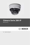
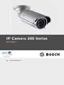
IP Camera 200 Series
NTC-265-PI
en
Installation Manual
IP Camera 200 Series
Table of Contents | en
3
Table of Contents
1
Safety
5
1.1
Safety precautions
5
1.2
Important safety instructions
6
1.3
FCC & ICES compliance
7
1.4
UL certification
8
1.5
Bosch notices
8
1.6
Copyrights
9
2
Introduction
2.1
Features
10
2.2
Unpacking
11
3
Installation
12
3.1
Assembly
12
3.2
Mounting
13
3.3
Network (and power) connector
14
3.4
Power connection
15
3.4.1
DC power connection
15
3.5
I/O connector
16
3.6
Audio connectors
17
3.7
Camera set-up
18
3.7.1
Camera positioning
19
3.8
Resetting the camera
20
4
Browser connection
21
4.1
System requirements
21
4.2
Establishing the connection
22
4.2.1
Password protection in camera
22
4.3
Protected network
22
5
Troubleshooting
23
5.1
Resolving problems
23
5.2
Customer service
23
Bosch Security Systems
10
Installation Manual
AM18-Q0610 | v1 | 2012.02
4
en | Table of Contents
IP Camera 200 Series
6
Maintenance
24
6.1
Repairs
24
6.1.1
Transfer and disposal
24
7
Technical Data
25
7.1
Specifications
25
7.1.1
Accessories
26
AM18-Q0610 | v1 | 2012.02
Installation Manual
Bosch Security Systems
IP Camera 200 Series
Safety | en
1
Safety
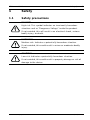
1.1
Safety precautions
5
DANGER!
High risk: This symbol indicates an imminently hazardous
situation such as "Dangerous Voltage" inside the product.
If not avoided, this will result in an electrical shock, serious
bodily injury, or death.
WARNING!
Medium risk: Indicates a potentially hazardous situation.
If not avoided, this could result in minor or moderate bodily
injury.
CAUTION!
Low risk: Indicates a potentially hazardous situation.
If not avoided, this could result in property damage or risk of
damage to the device.
Bosch Security Systems
Installation Manual
AM18-Q0610 | v1 | 2012.02
6
en | Safety
1.2
IP Camera 200 Series
Important safety instructions
Read, follow, and retain for future reference all of the following
safety instructions. Heed all warnings on the unit and in the
operating instructions before operating the unit.
1.
Cleaning - Generally, using a dry cloth for cleaning is
sufficient but a moist, fluff-free cloth or leather shammy
may also be used. Do not use liquid cleaners or aerosol
cleaners.
2.
Heat Sources - Do not install the unit near any heat
sources such as radiators, heaters, stoves, or other
equipment (including amplifiers) that produce heat.
3.
Water - Never spill liquid of any kind on the unit.
4.
Lightning - Take precautions to protect the unit from
power and lightning surges.
5.
Controls adjustment - Adjust only those controls specified
in the operating instructions. Improper adjustment of
other controls may cause damage to the unit.
6.
Power sources - Operate the unit only from the type of
power source indicated on the label.
7.
Servicing - Unless qualified, do not attempt to service this
unit yourself. Refer all servicing to qualified service
personnel.
8.
Replacement parts - Use only replacement parts specified
by the manufacturer.
9.
Installation - Install in accordance with the manufacturer's
instructions and in accordance with applicable local codes.
10. Attachments, changes or modifications - Only use
attachments/accessories specified by the manufacturer.
Any change or modification of the equipment, not
expressly approved by Bosch, could void the warranty or,
in the case of an authorization agreement, authority to
operate the equipment.
AM18-Q0610 | v1 | 2012.02
Installation Manual
Bosch Security Systems
IP Camera 200 Series
1.3
Safety | en
7
FCC & ICES compliance
FCC & ICES Information
This equipment has been tested and found to comply with the
limits for a Class B digital device, pursuant to part 15 of the
FCC Rules. These limits are designed to provide reasonable
protection against harmful interference in a residential
installation. This equipment generates, uses, and can radiate
radio frequency energy and, if not installed and used in
accordance with the instructions, may cause harmful
interference to radio communications. However, there is no
guarantee that interference will not occur in a particular
installation. If this equipment does cause harmful interference
to radio or television reception, which can be determined by
turning the equipment off and on, the user is encouraged to try
to correct the interference by one or more of the following
measures:
–
reorient or relocate the receiving antenna;
–
increase the separation between the equipment and
receiver;
–
connect the equipment into an outlet on a circuit different
from that to which the receiver is connected;
–
consult the dealer or an experienced radio/TV technician
for help.
This device complies with part 15 of the FCC Rules. Operation
is subject to the following two conditions:
1.
this device may not cause harmful interference, and
2.
this device must accept any interference received,
including interference that may cause undesired operation.
Intentional or unintentional modifications, not expressly
approved by the party responsible for compliance, shall not be
made. Any such modifications could void the user's authority to
operate the equipment. If necessary, the user should consult
the dealer or an experienced radio/television technician for
corrective action.
Bosch Security Systems
Installation Manual
AM18-Q0610 | v1 | 2012.02
8
en | Safety
IP Camera 200 Series
The user may find the following booklet, prepared by the
Federal Communications Commission, helpful: How to Identify
and Resolve Radio-TV Interference Problems. This booklet is
available from the U.S. Government Printing Office,
Washington, DC 20402, Stock No. 004-000-00345-4.
1.4
UL certification
Disclaimer
Underwriter Laboratories Inc. ("UL") has not tested the
performance or reliability of the security or signaling aspects of
this product. UL has only tested fire, shock and/or casualty
hazards as outlined in UL's Standard(s) for Safety for Closed
Circuit Television Equipment, UL 2044. UL Certification does not
cover the performance or reliability of the security or signaling
aspects of this product.
UL MAKES NO REPRESENTATIONS, WARRANTIES, OR
CERTIFICATIONS WHATSOEVER REGARDING THE
PERFORMANCE OR RELIABILITY OF ANY SECURITY OR
SIGNALING RELATED FUNCTIONS OF THIS PRODUCT.
1.5
Bosch notices
Disposal - Your Bosch product was developed and
manufactured with high-quality material and components that
can be recycled and reused. This symbol means that
electronic and electrical appliances, which have reached the
end of their working life, must be collected and disposed of
separately from household waste material. Separate collecting
systems are usually in place for disused electronic and
electrical products. Please dispose of these devices at an
environmentally compatible recycling facility, per European
Directive 2002/96/EC
More information
For more information please contact the nearest Bosch Security
Systems location or visit www.boschsecurity.com
AM18-Q0610 | v1 | 2012.02
Installation Manual
Bosch Security Systems
IP Camera 200 Series
1.6
Safety | en
9
Copyrights
The firmware 4.1 uses the fonts "Adobe-Helvetica-Bold-RNormal--24-240-75-75-P-138-ISO10646-1" and "AdobeHelvetica-Bold-R-Normal--12-120-75-75-P-70-ISO10646-1" under
the following copyright:
Copyright 1984-1989, 1994 Adobe Systems Incorporated.
Copyright 1988, 1994 Digital Equipment Corporation.
Permission to use, copy, modify, distribute and sell this
software and its documentation for any purpose and without
fee is hereby granted, provided that the above copyright
notices appear in all copies and that both those copyright
notices and this permission notice appear in supporting
documentation, and that the names of Adobe Systems and
Digital Equipment Corporation not be used in advertising or
publicity pertaining to distribution of the software without
specific, written prior permission.
This software is based in part on the work of the Independent
JPEG Group.
Bosch Security Systems
Installation Manual
AM18-Q0610 | v1 | 2012.02
10
en | Introduction
IP Camera 200 Series
2
Introduction
2.1
Features
The Bosch NTC-265-PI 720p infrared IP bullet camera is a readyto-use, robust network camera. This camera offers a cost
effective solution for a broad range of applications. The robust
aluminum camera body is IP66 rated, offering water and dust
proofing for demanding environments. The built-in active
infrared illuminator ensures effective vision under extreme lowlight conditions. The camera easily integrates with the Bosch
DVR 700 Series recorder and can also be used with an iSCSI
server connected via the network to store long-term recordings.
Features include:
–
High performance active infrared illuminator inside the
camera for extreme low-light environments
–
Tri-streaming: Two H.264 streams and one M-JPEG stream
–
HD 720p Progressive scan for sharp images of moving
objects
–
Robust IP66-rated camera design
–
Two-way audio and audio alarm
–
Power over Ethernet (IEEE 802.3af compliant)
–
Tamper and motion detection
–
Conforms to the ONVIF standard for wide compatibility
AM18-Q0610 | v1 | 2012.02
Installation Manual
Bosch Security Systems
IP Camera 200 Series
2.2
Introduction | en
11
Unpacking
Unpack carefully and handle the equipment with care.
The packaging contains:
–
IP camera with lens
–
Torx screwdriver
–
Camera fixing screw kit
–
Installation paper sticker
–
Quick installation guide
–
CD ROM
–
Bosch Video Client
–
Documentation
–
Tools
If equipment has been damaged during shipment, repack it in
the original packaging and notify the shipping agent or supplier.
WARNING!
Installation should only be performed by qualified service
personnel in accordance with the National Electrical Code or
applicable local codes.
CAUTION!
The camera module is a sensitive device and must be handled
carefully.
Bosch Security Systems
Installation Manual
AM18-Q0610 | v1 | 2012.02
12
en | Installation
IP Camera 200 Series
3
Installation
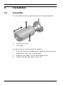
3.1
Assembly
The sun hood on the camera/housing unit can be adjusted.
1.
2.
Adjustment screw
Sun hood
To adjust the sun hood proceed as follows:
1.
Using the special screwdriver bit supplied, loosen the top
adjustment screw (1) in the housing.
2.
Slide the sun hood (2) to the desired position.
3.
Tighten the top adjustment screw (1).
AM18-Q0610 | v1 | 2012.02
Installation Manual
Bosch Security Systems
IP Camera 200 Series
3.2
Installation | en
13
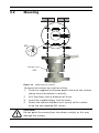
Mounting
Ø
6
m
m
x4
M4 (Ø3.3 mm)
x4
Figure 3.1
Mounting the camera
To mount the camera to a wall or ceiling:
1.
Stick the supplied installation paper sticker to the surface
taking care to orientate it correctly.
2.
Drill four holes with a diameter of 6 mm.
3.
Insert the supplied plugs into the holes.
4.
Attach the camera and base unit securly to the surface
using the two supplied M4 screws.
CAUTION!
Do not point the camera/lens into direct sunlight as this may
damage the sensors.
Bosch Security Systems
Installation Manual
AM18-Q0610 | v1 | 2012.02
14
en | Installation
3.3
IP Camera 200 Series
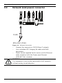
Network (and power) connector
RJ45
Ethernet (PoE)
Figure 3.2
Network connection
–
Connect the camera to a 10/100 Base-T network.
–
Use a shielded UTP Category 5e cable with RJ45
connectors.
–
Power can be supplied to the camera via the Ethernet
cable compliant with the Power-over-Ethernet
(IEEE 802.3af) standard.
CAUTION!
This equipment is only to be connected to PoE networks
without routing to outside plant.
AM18-Q0610 | v1 | 2012.02
Installation Manual
Bosch Security Systems
IP Camera 200 Series
3.4
Installation | en
15
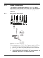
Power connection
The camera can accept power from both the DC12V power
input and the Ethernet input at the same time. You can remove
either one of the power sources without interrupting camera
operation.
3.4.1
DC power connection
5 mm
(0.2 in)
22AWG
12 VDC
Figure 3.3
DC power connection
Connect power from a 12 VDC class 2 power supply as follows:
1.
Use AWG22 wire; cut back 5 mm (0.2 in) of insulation.
2.
Remove the 2-pole connector from the camera cable tree.
3.
Loosen the screws and insert the wires.
4.
Tighten the screws and reconnect the 2-pole connector to
the power connector of the camera cable tree.
Bosch Security Systems
Installation Manual
AM18-Q0610 | v1 | 2012.02
16
en | Installation
3.5
IP Camera 200 Series
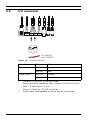
I/O connector
5 mm
(0.2 in)
In: AWG30
Out: AWG20
Figure 3.4
I/O connector pins
Function
Wire
Color
Relay out
AWG20
Grey
AWG20
Red
AWG30
Orange
AWG30
Brown
Alarm input
–
Cut back 5 mm (0.2 in) of insulation.
–
Relay switching capability: Max. voltage 24 VAC or 24 VDC.
–
Alarm in: Short or +5 VDC activation.
–
Alarm input configurable as active low or active high.
Max. 1 A continuous, 12 VA.
AM18-Q0610 | v1 | 2012.02
Installation Manual
Bosch Security Systems
IP Camera 200 Series
3.6
Installation | en
17
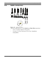
Audio connectors
Line - L
GND
Line - R
Figure 3.5
Audio connectors
Connect audio devices to the Line In and Line Out connectors.
–
Line in: 9 kOhm typical, 200 mVrms
–
Line out: 16 Ohm minimum 200 mVrms (earphone
compatible)
Bosch Security Systems
Installation Manual
AM18-Q0610 | v1 | 2012.02
18
en | Installation
3.7
IP Camera 200 Series
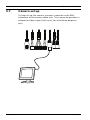
Camera set-up
To help set up the camera, connect a monitor to the BNC
connector of the camera cable tree. This connector provides a
composite video signal (with sync) for installation purposes
only.
AM18-Q0610 | v1 | 2012.02
Installation Manual
Bosch Security Systems
IP Camera 200 Series
3.7.1
Installation | en
19
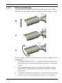
Camera positioning
The camera position can be adjusted along three axes. When
adjusting ensure that the picture display on the monitor is level.
Set the camera to the desired position using the supplied Torx
screwdriver:
1.
For vertical adjustment (1), loosen the locking screw and
move the camera housing to the desired angle. Tighten the
screw.
2.
For horizontal adjustment (2), loosen the locking screw
and rotate the camera housing around the base. Tighten
the screw.
3.
To obtain a horizontal horizon (3), rotate the camera body
as necessary to align the picture shown on the monitor.
Bosch Security Systems
Installation Manual
AM18-Q0610 | v1 | 2012.02
20
en | Installation
3.8
IP Camera 200 Series
Resetting the camera
If the camera cannot be connected because the IP address has
changed, short circuit the reset connector for approximately
7 seconds to recall the factory default values. The factory
default IP address is 192.168.0.1
AM18-Q0610 | v1 | 2012.02
Installation Manual
Bosch Security Systems
IP Camera 200 Series
4
Browser connection | en
21
Browser connection
A computer with Microsoft Internet Explorer can be used to
receive live images from the camera, control cameras, and
replay stored sequences. The camera is configured over the
network using a browser or via the Bosch Video Client
(supplied with the product).
4.1
System requirements
–
–
Microsoft Internet Explorer version 7.0 or higher
Monitor: resolution at least 1024 × 768 pixels, 16 or 32 bit
color depth
–
Intranet or Internet network access
The Web browser must be configured to enable Cookies to be
set from the IP address of the unit.
In Windows Vista, deactivate protected mode on the Security
tab under Internet Options.
To play back live video images, an appropriate ActiveX must be
installed on the computer. If necessary, the required software
and controls can be installed from the product disk provided.
a.
Insert the disk into the optical drive of the computer.
If the disk does not start automatically, open the root
directory of the disk in Windows Explorer and double
click BVC-installer.exe
b.
Follow the on-screen instructions.
To get full support for recordings and snapshots, install the
MPEG_ActiveX from the product disk to your computer.
Bosch Security Systems
Installation Manual
AM18-Q0610 | v1 | 2012.02
22
en | Browser connection
4.2
IP Camera 200 Series
Establishing the connection
The camera must be assigned a valid IP address to operate on
your network. The default address pre-set at the factory is
192.168.0.1
1.
Start the Web browser.
2.
Enter the IP address of the camera as the URL.
Note:
If the connection is not established, the maximum number of
possible connections may already have been reached.
Depending on the device and network configuration, up to 25
web browsers, or 50 Bosch VMS connections are supported.
4.2.1
Password protection in camera
A camera offers the option of limiting access across various
authorization levels. If the camera is password-protected, a
message to enter the password appears.
1.
Enter the user name and the associated password in the
2.
Click OK. If the password is correct, the desired page is
appropriate fields.
displayed.
4.3
Protected network
If a RADIUS server is used for network access control (802.1x
authentication), the camera must be configured first. To
configure the camera for a Radius network, connect it directly
to a PC via a crossed network cable and configure the two
parameters, Identity and Password. Only after these have been
configured can communication with the camera via the network
occur.
AM18-Q0610 | v1 | 2012.02
Installation Manual
Bosch Security Systems
IP Camera 200 Series
Troubleshooting | en
5
Troubleshooting
5.1
Resolving problems
23
The following table is intended to help identify the causes of
malfunctions and correct them when possible.
Malfunction
Possible causes
Solution
No image
Faulty cable connections. Check all cables, plugs,
transmission to
contacts and
remote location.
connections.
No connection
The unit's configuration.
Check all configuration
established, no
parameters.
image transmission. Faulty installation.
Check all cables, plugs,
contacts and
connections.
5.2
Customer service
If a fault cannot be resolved, please contact your supplier or
system integrator, or contact Bosch Security Systems
Customer Service directly.
The Installer should write down all information regarding the
unit so that it can be referenced for warranty or repair. The
version numbers of the firmware and other status information
can be seen when the unit starts or by opening the Service
menu. Note down this information and the information found
on the camera label before contacting customer service.
Bosch Security Systems
Installation Manual
AM18-Q0610 | v1 | 2012.02
24
en | Maintenance
IP Camera 200 Series
6
Maintenance
6.1
Repairs
CAUTION!
Never open the casing of the camera. The unit does not contain
any user serviceable parts. Ensure that all maintenance or
repair work is performed only by qualified personnel (electrical
engineering or network technology specialists). If in doubt,
contact your dealer's technical service center.
6.1.1
Transfer and disposal
The camera should only be passed-on together with this
installation guide. The unit contains environmentally hazardous
materials that must be disposed of according to law. Defective
or superfluous devices and parts should be disposed of
professionally or taken to your local collection point for
hazardous materials.
AM18-Q0610 | v1 | 2012.02
Installation Manual
Bosch Security Systems
IP Camera 200 Series
Technical Data | en
7
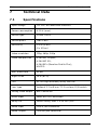
Technical Data
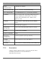
7.1
Specifications
Input voltage
+12 VDC or Power-over-Ethernet
Power consumption
6.72 W (max)
Sensor type
¼-inch CMOS
Sensor pixels
1280 x 800
Sensitivity
0.3 lx (IR off)
25
0 lx (IR on)
Video resolution
720p, 480p, 240p
Video compression
H.264 MP 720p30;
H.264 MP SD;
H.264 BP+ (Baseline Profile Plus);
M-JPEG
Max. frame rate
30 fps
Night vision
25 m (82 ft)
LED
32 LED high efficiency array, 850 nm
Lens type
Varifocal 2.7 to 9 mm, F1.2 to close, D/N switch
Analog video output
BNC connector
Alarm Input
Short or 5 VDC activation
Relay Out
Switch rating: Max. 1 A 24 VAC/VDC
Audio Input
Line in jack connector
Audio Output
Line out jack connector
Bosch Security Systems
Installation Manual
AM18-Q0610 | v1 | 2012.02
26
en | Technical Data
Audio
IP Camera 200 Series
Two-way, full duplex
communication
Audio compression
G.711, L16, AAC (live and recording)
Unit Configuration
Via web browser or PC surveillance software
Protocols
HTTP, HTTPs, SSL, TCP, UDP, ICMP,RTSP, RTP,
Telnet, IGMPv2/v3, SMTP,SNTP, FTP, DHCP
client, ARP, DNS,DDNS, NTP, SNMP, UPnP,
802.1X, iSCSI
Ethernet
10/100 Base-T, auto-sensing, half/full duplex,
RJ45
PoE
IEEE 802.3af compliant
Dimensions
100 x 100 x 291 mm (3.94 x 3.94 x 11.46 in)
(H x W x D)
Weight
1.6 kg (3.53 lb) approx.
Ingress Protection
IP66
Operating
-20 ºC to +50 ºC (-4 ºF to +122 ºF)
Temperature
Storage
-20 ºC to +70 ºC (-4 ºF to +158 ºF)
Temperature
Humidity
7.1.1
Less than 90% relative humidity (non-condensing)
Accessories
Contact a Bosch representative in your area for the latest
available accessories or visit our website at
www.boschsecurity.com
AM18-Q0610 | v1 | 2012.02
Installation Manual
Bosch Security Systems
Bosch Security Systems
www.boschsecurity.com
© Bosch Security Systems, 2012