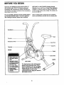
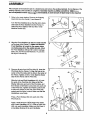
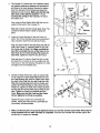
1
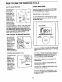
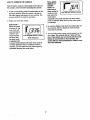
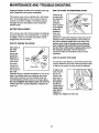
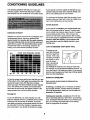
USER'S MANUAL
Model No. 831.288710
E_X
F-- C_ U
E: RC
I S
I P
M E
[e|liSBiRe|
E
N
T
_ |
HELPLINE!
1-800-736-6879
SEARS, ROEBUCK AND CO., HOFFMAN ESTATES, IL 60179
TABLE OF CONTENTS
IMPORTANT PRECAUTIONS .............................................................
BEFORE YOU BEGIN ...................................................................
ASSEMBLY ...........................................................................
HOW TO USE THE EXERCISE CYCLE ......................................................
MAINTENANCE AND TROUBLE-SHOOTING
.................................................
CONDITIONING GUIDELINES .............................................................
PART LIST ...........................................................................
EXPLODED DRAWING .................................................................
HOW TO ORDER REPLACEMENT PARTS ...........................................
FULL 90 DAY WARRANTY
.......................................................
2
2
3
4
6
8
9
10
11
Back Cover
Back Cover
BEFORE YOU BEGIN
Thank you for selecting the new LIFESTYLER ° DT
450 exercise cycle. The DT 450 blends advanced
engineering with contemporary styling to provide you
with effective, low-impact workouts in the convenience
and privacy of your home.
HELPLINE at 1-800-736-6879, Monday through
Saturday, 7 a.m. until 7 p.m. Central Time (excluding
holidays). To help us assist you, please mention the
product model number when calling. The model number is 831.288710.
For your benefit, read this manual carefully before
you use the exercise cycle. If you have questions
after reading the manual, please call our toll-free
Before reading further, please look at the drawing
below and familiarize yourself with the labeled parts.
Handlebars
Console
Resistance Knob
Seat Post
Seat Pin
Flywheel
FRONT
Pedal
Side Shield
• Mbuseoflhlsproduct
may resultinsedous
Injur/.
• Read user'smanual
andfollowallwarnings
and operatingInstructionspriorto use.
• Do notallowchildren
onor aroundmachine.
labelif
BACK
LEFT SIDE
The decal shown at the left has been
placed on the exercise cycle. If the
decal is missing, or if it is not legible,
please call our toll-free HELPLINE at
1-800736-6879 to order a free
replacement decal. Apply the decal in
the IocaUon shown.
3
ASSEMBLY
Place all parts of the exercise cycle in a cleared area and remove the packing materials. Do not dispose of the
packing materials until assembly is completed. Assembly requires a phlUlps screwdriver
and an adjustable wrench _
(not Included). A small amount of liquid soap Is also required.
:1. Refer to the inset drawing. Remove the Shipping
Insert (54) from the Frame (1) and discard it.
Turn the Rear Stabilizer (2) so that the slot is down,
and insert the Rear Stabilizer into the Frame (1).
Attach the Rear Stabilizer with four M5 x 10ram
Machine Screws (32).
2.
Align the Front Stabilizer (5) with the saddle bracket
on the front of the Frame (1). Make sure that the
Front Stabilizer is turned so the square holes
are facing away from the saddle bracket. Attach
the Front Stabilizer with two M8 x 40mm Carriage
Bolts (18), two M8 Curved Washers (14), and two
M8 Nylon Locknuts (9).
2 \
14
5._.
Square
Holes
18
3,
Remove all parts from the'Pivot Axle (3). Insert the
Pivot Axle into the Frame (1). Align the hole in the
center of the Pivot Axle with the hole in the center of
the Frame. Tighten an M5 x 10mm Machine Screw
(32) into the Frame and the Pivot Axle.
Slide the Left and Right Handlebars (40, 41) onto
the ends of the Pivot Axle (3). Slide an M8 Flat
Washer (38) onto each end of the Pivot Axle, and
then thread an M8 Nylon Locknut (9) onto each end
of the Pivot Axle. Tighten each Nylon Locknut until
at least two threads on the end of the Pivot AXle
extend past the Nylon Locknut. Make sure that the
Handlebars move freely.
3
42
38 9
50
Press a Pivot Endcap (50) onto each end of the
Pivot Axle (3).
Apply a small amount of liq_uidsoap to the upper
end of each Handlebar (40, 41). Slide a Foam Gdp
(42) onto each Handlebar. Make sure that there is
a Handlebar Endcap (8) in each Handlebar.
4
,
4. The Console (7) requires two "AA" batteries (included); alkaline replacement batteries are recommended. Refer to the inset drawing. Remove the battery
door from the back of the Console and insert two
\
Console
Plate
baftedes into the Console. Make sure that the negative ends of the batteries (marked "-") are
touching the springs in the Console. Re-attach
the battery door.
'-_28
Next, plug the Reed Switch Wire (28) fully into the
socket on the back of the Console (7).
/
Slide the Console onto the console plate. Note: The
Console is held by friction; it does not snap into
place.
5.
Batteries
Battery Door
Press the Frame Bushing (4) into the Frame (1).
(Note: The Frame Bushing may be pre-assembled.)
Next, insert the Seat Post (10) into the Frame.
5
11
_=
Align one of the holes in the Seat Post (10) with the
hole in the Frame (1). Insert the Seat Pin (31) into
the Frame and the Seat Post. Make sure that the
Seat Pin Is Inserted into one of the holes in the
Seat Post; do not insert the Seat Pin under the
Seat Post. Tighten the Seat Pin into the Frame.
Slide the Seat (11) onto the Seat Post (10) so that
the Seat Post is inserted as far as possible into the
hole shown in the inset drawing. Straighten the Seat
and tighten the two indicated nuts.
6.
Identify the Right Pedal (22), which is marked with
an =R." Remove only the Right Pedal Nut (47) and
the Pedal Bushing (46) from the Pedal. Next, insert
the shaft of the Pedal into the right Pedal Arm (49).
Slide the Pedal Bushing back onto the Pedal, and
position the Pedal Bushing so that it slides into the
Pedal Arm. Tighten the shaft of the Pedal clockwise
into the right arm of the Crank (20) as firmly as possible. Tighten the Pedal Nut clockwise onto the
Pedal. Make sure that the Pedal and the Pedal
Nut are tightened as firmly as possible.
6
47
Repeat this step to attach the Left Pedal (not
shown), turning the Pedal and the Left Pedal Nut
(not shown) counterclockwise.
7.
Make sure that all parts are properly tightened before you use the exercise cycle. Note: There may be
some hardware left over after assembly Is completed. Cover the floor beneath the exercise cycle to protect the floor or carpet from damage.
5
HOW TO USE THE EXERCISE CYCLE
HOW TO ADJUST THE SEAT
BATTERY INSTALLATION
For effective exercise, the seat
must be at the
proper height. As
you pedal, there
should be a slight
bend in your
knees when the
pedals are in the
lowest position. To
adjust the seat,
first hold the seat
and turn the seat
Before the console can be operated, two "AA" batteries must be installed, If you have not installed batteries, see assembly step 4 on page 5.
DESCRIPTION OF THE CONSOLE
The console features five modes that provide instant
exercise feedback dudngyour workouts. The modes
are described below.
Post
Pin
pin ocuntemlockwise to remove it. Next, align a different hole in the seat post with the hole in the frame,
and insert the seat pin Into the frame and the seat
post, Make sure to insert the seat pin into the seat
post; do not insert the seat pin under the seat
post. "lighten the seat pin into the frame.
Speed Display
l ,oc,_,l
HOW TO ADJUST THE PEDALING RESISTANCE
Mo_e/_
To vary the intensity of your exercise, the pedaling
resistance can be
adjusted. To
increase the resistance, turn the
resistance knob
clockwise; to
decrease the
resistance, turn the
knob countemlockwise.
Indicators@
_
OISTA,
NCEC_S
Display
• Scan mode---Displays the speed, time, distance, and
calodes modes, for five seconds each, in a repeating
cycle.
LEVELING THE EXERCISE CYCLE
The exercise cycle
features
• Time mode--Displays the elapsed time. Note: If you
stop pedaling for five seconds or longer, the time
mode will pause and a stop symbol will appear in
the upper right-hand comer of the display.
adjustable endcaps on the front
stabilizer, If the
• Speed mode--Displays your pedaling speed, in
miles per hour,
exercise cycle
rocks when it is
used, _m one or
both of the endcaps until the
rocking motion is
eliminated.
• Distance mods--Displays the total distance you
have pedaled, in miles.
Stabilizer
• Calories mode--Displays the approximate number
of calodes you have burned.
The console also features a speed display.As you
increase your pedaling speed, additional indicators
will appear in the bar.
6
HOW TO OPERATE THE CONSOLE
Time, speed,
distance, or
calories
mode--To
select one of
these modes for
continuous dis-
Note: If there is a piece of clear plastic on the face of
the console, remove it before operating the console.
1. To turn on the power, press the mode button or simply begin pedaling. When the power is turned on,
the entire display will appear for two seconds. The
console will then be ready for operation.
play, press the
mode button
I 1
Ir==',coI
I' io. "l
SCAN TIME SPEED OmTANCE CALORIE8
repeatedly. The mode indicators will show which
mode is selected. Make sure that the scan mode is
not selected.
2. Select one of the five modes:
Scan mode-When the power
is turned on, the
scan mode will
3. To reset the display, hold down the mode button for
two seconds. After the display is reset, the scan
mode will be selected.
automatically be
selected. One
mode indicator
will show that
the scan mode
is selected, and
a second mode indicator will show which mode is
currently displayed. Note: If a different mode is
selected, you can select the scan mode again by
repeatedly pressing the mode button.
f!' ,-,.-,,- 1 I
'c-
7
4. To turn off the power, simply wait for about four minutes. Note: The console has an "auto-off" feature. If the pedals are not moved and the rnode
button is not pressed for four minutes, the
power will turn off automatically in order to conserve the batteries.
MAINTENANCE AND TROUBLE-SHOOTING
HOW TO ADJusT THE RESISTANCE STRAP
Inspect and tighten all parts of the exercise cycle regulady. Replace any worn parts immediately.
If there is not
The exercise cycle can be cleaned with a soft, damp
cloth. Avoid spilling liquid on the console. Keep the
console out of direct sunlight or the display may be
damaged. Remove the batteries when storing the
exercise cycle.
enough pedaling resistance
when the
resistance
knob is turned
Slotted
Tab
Resistance
to the highest
setting, the
resistance
strap may
need to be
BATTERY REPLACEMENT
If the console does not function properly, the batteries
should be replaced. See assembly step 4 on page 5.
In addition, make sure that the reed switch wire is
plugged fully into the console.
adjusted. To adjust the resistance strap, first turn the
resistance knob counterclockwise to the lowest setting. Next, locate the slotted tab on the front of the
exercise cycle. Gdp the longest part the resistance
strap undemeath the slotted tab and pull It towards
the slot. When a little slack is created, pull the end of
the resistance strap tight. Tum the crank for a
moment to make sure that there is not too much
resistance.
HOW TO TIGHTEN THE CRANK
If the arms of
the crank
become
loose, they
__Slotted
should be
tightened in
Cran_
Crank
order to prevent excessive wear.
Nut_
Loosen the
crank nut on
Crank Arm
the left arm of
the crank.
Place the end of a standard screwddver in one of the
slots in the slotted crank nut. Lightly tap the screwddver with a hammer to turn the slotted crank nut
HOW TO ADJUST THE CHAIN
The exercise cycle features a chain that must be kept
properly adjusted. If the chain causes excessive noise
or slips as you pedal, the chain should be adjusted.
To tighten the
chain, loosen,
but do not
remove, the
axle nuts on
both sides of
the flywheel.
Pull the flywheel forward
Nut
slightly. Make
sure that the
flywheel is
straight and retighten the axle nuts.
counterclockwise until the arms are no longer loose.
Do not overtighten the slotted crank nut. When the
slotted crank nut is propedy tightened, retighten the
crank nut.
8
CONDITIONING GUIDELINES
The following guidelines will help you to plan your
exercise program. Remember that proper nutdtion
and adequate rest am essential for successful results.
If your goal is to bum fat, adjust the intensity of your
exercise until your heart rate is near the lowest number in your training zone as you exercise.
For maximum fat burning, adjust the intensity of your
exercise until your heart rate is near the middle number in your training zone as you exercise.
Aerobic Exercise
If your goal is to strengthen your cardiovascular system, your exercise must be =aerobic." Aerobic exercise is activity that requires large amounts of oxygen
for prolonged periods of time. This increases the
demand on the heart to pump blood to the muscles,
and on the lungs to oxygenate the blood. For aerobic
exercise, adjust the intensity of your exercise until
your heart rate is near the highest number in your
training zone.
EXERCISE INTENSITY
Whether your goal is to burn fat or to strengthen your
cardiovascular system, the key to achieving the
desired results is to exercise with the proper intensity.
The proper intensity level can be found by using your
heart rate as a guide. The chart below shows recommended heart rates for fat burning, maximum fat
burning, and cardiovascular (aerobic) exemise.
BPM
HEART RATE TRAINING
HOW TO MEASURE YOUR HEART RATE
To measure your
heart rate, first exercise for at least four
minutes. Then, stop
exercising and place
two fingers on your
wrist as shown.
Take a six-second
heartbeat count,
and multiply the result by 10 to find your heart rate.
For example, if your six-second heartbeat count is 14,
your heart rate is 140 beats per minute. (A six-second
count is used because your heart rate will drop rapidly
when you stop exercising.)
ZONES
IliMtEIgW
•, iimililgllm
,%e 2o
30
40
50
60
7o
80
WORKOUT GUIDEUNES
To find the proper heart rate for you, first find your age
at the bottom of the chart (ages are rounded off to the
nearest ten years). Next, find the three numbers
above your age. The three numbers are your =training
zone." The lowest two numbers are recommended
heart rates for fat burning;the highest number is the
recommended heart rate for aerobic exercise.
Each workout should include the following three
important pads:
A warm-up, consisting of 5 to 10 minutes of stretching and light exercise. A proper warm-up increases
your body temperature, heart rate, and circulation in
preparation for exercise.
Burning Fat
Training zone exercise, consisting of 20 to 30 minutes of exercising with your heart rate in your training
zone. (During the first few weeks of your exercise program, do not keep your heart rate in your training
zone for longer than 20 minutes.)
To bum fat effectively, you must exercise at a relatively low intensify level for a sustained pedod of time.
Dudng the first few minutes of exercise, your body
uses easily accessible carbohydrate calodes for energy. Only after the first few minutes of exercise does
your body begin to use stored fat calodes for energy.
9
A cool.down, with 5 to 10 minutes of stretching. This
will increase the flexibility of your muscles end will
help to prevent post-exercise problems.
EXERCISE FREQUENCY
may complete up to five workouts each week, if
desired. CAUTION: Be sure to progress at your
own pace and avoid overdoing it. Incorrect or
exceaalve training may result In Injury to your
health,
To maintain or improve your condition, plan three workouts each week, with at least one day of rest between
workouts. After a few months of regular exercise, you
i
Remember, the key to success is make exercise a
regular and enjoyable part of your everyday life.
i
PART LIST--Model No. 831.288710
Key No. Qty.
Description
R0801A
Key No. Qty.
Description
1
2
3
4
5
6
7
1
1
1
1
1
2
1
Frame
Rear Stabilizer
Pivot Axle
Frame Bushing
Front Stabilizer
Front StablUzer Endcap
Console
30
31
32
33
34
35
36
1
1
5
2
1
1
2
M5 x 15mm Screw
Seat Pin
M5 x 10mm Machine Screw
M8 Custom Flat Washer
Resistance Spdng
Sprocket
M8 x 43ram Bolt .
8
9
10
11
12
13
14
15
16
17
18
19
20
21
22
23
24
25
26
27
28
29
2
6
1
1
1
2
2
6
1
1
2
1
1
1
1
1
1
4
1
4
1
2
Handlebar Endcap
M8 Nylon Locknut
Seat Post
Seat
Right Side Shield
Bronze Bushing
M8 Curved Washer
M5 x 10mm Self-tapping Screw
Flywheel
Resistance Strap
M8 x 40ram Carriage Bolt
Crank Bearing Assembly
Crank
Left Pedal
Right Pedal
Chain
Resistance Cable/Knob
7116" Flat Washer
Flywheel Axle
3/8" Axle Nut
Reed Switch/Wire
3/8" Axle Nut
37
38
39
40
41
42
43
44
45
46
47
48
49
50
51
52
53
54
#
#
#
2
4
2
1
1
2
6
2
1
2
1
1
2
2
2
1
1
1
1
t
1
Pedal Arm Bushing
M8 Flat Washer
Round Endcap
Left Handlebar
Right Handlebar
Foam Grip
Pivot Bushings
1/2" Flat Washer
Left Side Shield
Pedal Bushing
Right Pedal Nut
Left Pedal Nut
Pedal Arm
Pivot Endoap
M5 Flat Washer
Wire Clip
Resistance Control Housing
Shipping Insert
User's Manual
13mnY15mm Multi-puq0ose Tool
13mm/19mm Multi-purpose Tool
Note: "#" refers to a non-illustrated part. Specifications are subject to change without notice. See the back cover
of this manual for information about ordering replacement parts.
10
EXPLODED DRAWING--Model
No. 831.288710
ROSOlA
29
28
8
25
27
42
26
13 \
8
27
5O
9
9
43
19
20
15
32
52
31
51_
32
45
2
15
39
34
2O
21
49
49
18
11
All replacement parts are available for Immediate purchase or
special order when you visit your nearest SEARS Service Center.
To request service or to order parts by telephone, call the toll-free
numbers listed at the left.
Model No. 831.288710
QUESTIONS?
When requesting help or service, or ordering parts, please be
prepared to provide the following information:
If you find that:
• you need help assembling or
operating the LIFESTYLER" DT
450
• a part is missing
• or you need to schedule repair
service
• The MODEL NUMBER of the product (831.288710)
• The NAME of the product (LIFESTYLER ® DT 450 exercise
cycle)
• The KEY NUMBER and DESCRIPTION of the PART (see the
PART LIST and the EXPLODED DRAWING on pages 10 and 11).
call our toll-free HELPLINE
1-800-736-6879
Monday-Saturday, 7 am-7 pm
Central Time (excluding holidays)
REPLACEMENT
PARTS
If parts become worn and need to
be replaced, call the following tollfree number
1-800-FON-PART
(1-800-366-7278)
FULL 90 DAY WARRANTY
i ,
I
For 90 days from the date of purchase, if failure occurs due to defect in material or workmanship in this
SEARS BIKE EXERCISER, contact the nearest SEARS Service Center throughout the United States
and SEARS will repair or replace the BIKE EXERCISER, free of charge.
This warranty does not apply when the BIKE EXERCISER is used commercially or for rental puq_oses.
This warranty gives you specific legal dghts, and you may also have other rights which vary from state
to state.
SEARS, ROEBUCK AND CO., DEPT. 817WA, HOFFMAN ESTATES, IL 60179
Part No. 177533 R0801A
Printed in Taiwan © 2001 Sears, Roebuck and Co.