1
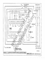
w
in w
fo .w
@ a
w dk
ad in
ki .co
n. m
co
m
•
BRA 350/ 400/ 450
Universal Radial Arm Saw
w
Instruction Manual
BE CAREFUL
THIS MACHINE CAN BE DANGEROUS
IF IMPROPERLY USED
w
in w
fo .w
@ a
w dk
ad in
ki .co
n. m
co
m
Always use guards.
Keep clear until rotation has ceased.
Always operate as instructed
and in accordance with good practice.
Read instruction manual before installing,
operating or maintaining machine.
-I-!
Manufactured by: A L Dalton Ltd
Crossgate Drive
Queens Drive Ind Est
Nottingham
NG21 LW
United Kingdom
~~? ;~~~
.
015
w
Telephone Number: 0870 850 9111
Fax Number: 0870 240 0575
Website: www.wadkin.com
Email: [email protected]
MODEL TYPE:
YEAR:
SERIAL NO:
VOLTS:
HP:
PH:
HZ:
The fol lowing machine has undergone ' Conformity Assessmen t" and has undergone Self
Assessment in accordance with:-
w
in w
fo .w
@ a
w dk
ad in
ki .co
n. m
co
m
Schedule IV of the Supply of Machinery (Safety) Regulations 1992
and Amendment No. 2063
COMPANY
Wadkin Ultracare limited
Frank.s Road
Hilltop Industrial Park
Bardon
Leicestershire
LE67 lIT
RESPONSIBLE PERSON
Mr J P Smith (Director)
MACHINE DESCRIPTION
Cross Cut Saw
MODEL
BRA
w
TYPE
DIRECTIVES COMPLIED WITH
Supply of Machinery (Safety) Regulations 1992
Amendment No. 2063 1994
Draught Proposal CENfTC 142
ISO 9001 Part 1
SIGNED ON BEHALf OF WADKIN
UL TRACARE LTD .
~
... ................... .....
...... .................
PREFACE
w
in w
fo .w
@ a
w dk
ad in
ki .co
n. m
co
m
IMPORTANT
It is our policy and that of our suppliers to constanlly
review the design and capacity of our products. With this
in mind we would remind our customers that while the
dimensions and pertormance data contained herein are
correct at the time of going to press, It is possible that due
to the incorporation of the latest developments to enhance
performance, dimensions and suppliers may vary from
those illustrated.
w
Th is manual is written as a general guide . A typical
machine is shown to illustrate the main features. For
reason of clarity certain guards, safety devices and
machine p~rts may not be shown on particular illustrations
but MUST be fixed to the machine, correctly set and
working before operating.
Failure to comply With instrucllons in this
manual may invalidate the guarantee.
HEALTH AND SAFETY
The CE mark on this maehillC signifies that
an EC dedaration of oonformily is drawn up
indicating that the machine ia manufactured
in accordance with the Essential Health and
Sa fety Requirements of the 'Supply of
Machinery (Safely) Regulations 1992.'
follows:
regulation 6 · malntell3.noo
regulation 7 - specific risks
regulaMn
a - information and insttuc~ons
w
in w
fo .w
@ a
w dk
ad in
ki .co
n. m
co
m
The 'requirements 101 supply of relevent
machinery' in the General Requ irement 01 the
Reguletions are not only that the machine
satlslies the relevant assentla l health and
safety requi re men ts, Dut also that 'the
manulacture ..... carries out the necessary
research or lests on components , fittings or
the complete machine 10 determine wh(lth\!r
by its design or construction Ih\! machine is
capabts of bslng erected and put Into service
safely.'
Tho Provision and Uso 01 Work Equipment
Regulations also indude requirements as
PGr sons who install this machine have duties
under Ihe 'Provisi on and Use 01 Work
Equipment Regulations 1992'. An indication
o f these duties Is given In the following
extracts, but lt1e user should be familiar with
the lull Implications ollhe regulations.
REGULATION 5 requires that;
Every employer shall ensure Ihat work
equipment is 50 constrocted Of adapted as to
be suitable for the purpose lor which it is
used or provided.
w
In selecting work equipment, every employer
shall heve regard to the working conditions
and to the risks to heallh end safety 01
pe rs ons whleh exist in Iho prom i"o" or
undertakings in which tha\ work equ ipment is
to be used and any additional risk posed by
the USII of that work equ ipment.
Every employer shall ensure that work
equipment is used only for the operations lor
which, and under cond itions lor which, it is
suitable.
In lhls regulation 'suitabte' means suitable in
any respect whi(:h it is reasonab ly
foreseaable will affect health or safely of any
person.
regulation 9 - train ing
Note:-
Attention is drawn 10 those requirements of
the 'Woodworking Machines Regulations
1974' which are 1"101 replaced by the Supply of
M achln ~ry (Safety) Re9ulations or oth~r, ~.g.:
Regulation 13 of the Wooctworking Machinery
Rsgulation, - 'Training', still appj ies.
Whilst the prime duly for Bf1suring health and
safely res ts with emptoyers, employoes too
have legal duties, particularly under sections
7 and a of the Health and Safety at Work Act.
They Include:
Tak ing reasonabl ~ CSr8 for their own heallh
and safety and that 01 oth ers who may be
affected by what they do or don't do;
co-operating with Iheir employer
and safely:
on
health
nol interfering with Of misusing anythi ng
provided for their health, safely and welfare.
Those dutie6 on employaes have been
supp le mented by rogu la\ion 12 ot the
Management of Health and Safely at Work
Regu lalions '992. One 01 the new
raquirements is that employees should use
correctly all work items provided by the ir
employer in acco rdance with their training
and Ihe Instructions they receive to enabte
them to use the items safely.
Noise
Du s t
Noise levels can vary widely lrom machine to
machine depending 0fI the condilions 01 use.
Persons e~po5ed 10 high noise levels, even
for a short time, may e~perience lemporary
paftial hearing loss and continuous e~posure
to high levels can resu lt i n permanent
hearing damage.
Wood dust can be harmful to hea lth by
and skin contact
and
inhala ti on
cOrlcentratlons cf small particles in the air
can form an explosive mixture.
w
in w
fo .w
@ a
w dk
ad in
ki .co
n. m
co
m
The COlltrol 01 Substances Hal:ardous to
Heatth Reg ulations (COSHH) 1989 place
legal duties on employers to ensure that:-
The Noi~e at Work RegulatiOns 19139 piece
legal oolies on employers to prevent damage
to hearing.
There are three action levels Of noise delined
in regulatiOfl 2:
The first action lowl:·
a daily personal noise
85dB(A)
e~posure
(LEP'd) of
The second action level;·
a daily personal noise exposure (LEP'd) 01
9()(jB(A)
The peak action level:·
A peak sound pressure of 200 pascals
(14006 re 2Opa)
The exposure level is obviously influenced by
the emission level of all the equipment in use,
w
Emissions levels fOl machines are provided
in the particular madline instruction manual.
These levels are measured in accordallce
with ISO 7960 under certain speclflea test
conditions , they do not necessarily represent
the hlghesl noise level, which is influenced by
many !actors, e,g. number ot epindles in
operalion, type and condition of work piece,
spindle speeds etc.
For regu lations and information on re levant
personal protective equipment i. e. ear
defenders, employers should reler to the
Pe rson a l Protective Equ ipment al Work
Regulations 1992.
the exposure of his employees to SUbSIElnces
hazardous to health is either prevented Of,
where this is flOt reasonably prac ticable,
adequately controlled.
.. .. ad e quate control to e~posure of
employees to a sub$tance hazardous to
health Shall be secured by measures other
than the provision of personal protective
equ ipment.
where the measures taken in accordance
with the para9raph above do not prevant or
provide adequate contro l of, exposure to
subs tances hal:ardous to tile health of
emptoyees, then In addition to tacking those
mothods, tho employor shall provide thoso
emp loyees with suc h suitab le personal
protective equipment as will adequately
control their expo sure to substances
hazardous to health.
In st r uc lfons for Use
Machinery manufactures el e required by tile
Supply of Machinery Safety Regulations to
provide eomprehens ive 'Instruct ions for Use"
of equ ipment, it is important that this
Information Is transmitted to the person using
the machine.
LIFTING AND TRANSPORTATION
Tran~p<)natlOn
L)' n1CnSlOnS and
Welghts_
UNLOAD ING
w
in w
fo .w
@ a
w dk
ad in
ki .co
n. m
co
m
Fig.1
Ensure thm all lifting cquipmenl used
is capable ofl iftillg the weight of the
machine a. a min imum.
The machme may be movC{1 uSlIlg a
fork lift tmck wilh the fork~ positi oned
under the saw table, full width.
No lt: - The forks must be positioned
from the side Oflhc machine (Fig. 1) in
order 10 prevent damage to the rCaI
guard.
AitCnl,,(ively it may be crone lifted . "I'D
l ift, plnce a "l i ng through the motor
stirrup ensuring lhe motor slide lock is
engaged to prevent unit movcment
( Fig.2 & 3 ). Slowly lift th e mach ine
ensuring it does not tilt and the slillg is
not ~Iipping
Move
Fig.2
Ih~ m"~hi,,c c"r~ru l ly
(0 the
site avoiding jolting Or
vibration.
w
pr~p~rcd
WARN I NC: Do not wa lk or stand
undCrnCJlh a raised ITIllch in e.
Fi gJ
I)\l PAC K1 NG
Remow the packaging mate rial from
all the i t~llls '''Id check that no (k'lllage
hHS octurret! d um,!; trm,s, t.
Ascertain that the Illachinc IS complele
with all fittings, rcquc~tcd accessorie s
and 1001 kit.
BRA ClWSSCIJT SAW
RADIAL ARM CROSSCUT SAW BRA 350
Maximum diameter of saw
350 mm
133/4 In
Maximum saw projection
108mm
4 114 in
Width will croa,cut with
Staildard arm
Width
a' 90 '
415
x 108 mm
Height of wor1oc table
Diameter 01 aaw spindle
Power of motor (Intermittent)
POWtir of motor (Intennittenl)(Optional)
Speed of motor, 50 hertz
Speed of motor. 60 hertz
Maximum 0VftnI1 height
Floor space
Net we ight (apprOK.)
Gron weight (approx,)
Shipping dlm&nllon, (appro~ .)
114 in
18314~l in
x 108 mm
s3/4x41 /4 in
288 x 25 mm
11 114 xl ,n
227
w
in w
fo .w
@ a
w dk
ad in
ki .co
n. m
co
m
Standard arm at 45'
x4
x 25 mm
480
wt. croueut with
16 114
..' ...
1105 mm
31x 1/2 in
30 mm
3 Kw
4.5 Kw
3000 rpm
3600 rpm
1790 mm
"mm
1170 x 1600 mm
210 kg
316 kg
0,99 CIJ m
70 ' 1!5 in
.,,.
46~63 1n
6951b
35 cu It
RADIAL ARM CROSSCUT SAW BRA 400
Maximum diameter 01 $ilW
400 mm
15 3/4 In
Maximum aaw projection
133 mm
39Q. 133 mm
5 1/sin
15 114K5 1/Sin
4SO~25 mm
17 s/S x 1 in
IIOxH3mm
41/4 X S1/Sin
260x25mm
10 1/4X 1 in
' '"mm
mm
31 1/2in
Width will Cl06SCU\ wlVl
Standard arm at 90'
Width will crosscut with
w
Standard arm a14S'
Height of wart< l8bte
Diameter of saw spindle
Power of motorj Intermittant)
Spee<J of motor, 50 hertz
Speed of motor, 60 hertz
Maximum overall height
,- .....
Nel weight (approx.)
Gross weight (eppl'Ox.)
Shipping dimef"ions (approx.)
4.5 Kw
3(lOO rev/min
3600 rev/mln
1790 mm
1170x 1650 mm
240 kg
346 kg
0.99cum
" mm
' ..
70 1/2 in
46x63in
52SIb
761 It)
35 CIJ n
iNSTRUCTIONS FOR FmlNG WOOD TABLE AND WEDGES TO BRA MACHINE
2 - MB)( 60 long
STAYS - - ,
2 · M8l( 60 long
~~~,:~ r~"'~~0-~=TR1E=:OAR :F:MA~C:HT'N:E:y=t,~~n ~~~;~:
ti'-;'?;:':::::;:~'~
'~'~:::~WOODP"'CKING
~
BLOCK
w
in w
fo .w
@ a
w dk
ad in
ki .co
n. m
co
m
WEDGE -~
~:.-=0r~'~~ri'~~'f'
W
O
O
D
PACKI
N
@
"'-OCK
1 • S dill x 25 long
GROVERLOK
DOWEL
1 . 5 aia X 2t; long
---,+.+---.Jlj.---!:J--- -...,!:4k,---
GROVERLOK
DOWEL
, I
:+:
:t :
11
:'-1
;->+"ty_
: I
6-M6p~~~8
I1
I1
I I
, I
SCREWS
1
-
, I
I
I I
I LtI.. 1,____ _ iJ
, ' ___ ....o...J
... , _ ____ J .. I
r L- _ _ _ _ _ _ _ _ _ _ _ _ _ ... I
1'
SHOATARM
TADLE
'----~ • I
I I
!..J
I_J
LONG ARM
~,---f---
VIEW LOOKING DOWN ON BASE
TABLE
FIG . 1
Refe r 10 FIG. 1
Place wood table against 2 ofIS dia x 25 long groYl!f1ock dowels.
w
I.
2.
3.
FastaJ1 13b18 In position by 6 off Ma x 35 long pan MAd SC' 8W5. (suppllfld complete with M6
nuts and washers).
RemOve gro~6r1oc1( doWels.
4. Position fence and packing pieces behind table.
S.
Place wood packing blocks over 8 dia holes on stays of base.
6.
Fit left hand and righl hand lable wedges in position wlItl4 011 Me x 60 ~g pan heed screws.
(supplied comp lete with Ma nuts and washerl), (Do not lasten tighUy).
7.
FII lable wedges In between packing pieces and left hand and right hancl table weO\Iel.
8.
l ock up 4 off MS x 60 long pan head screws.
INSTALLATION
~,oo
Remove protective coating lram bright parts
by applying a cloth soaked in paraffin ,
turpentine or some othe r $olvenl.
START
~
I
f
1 OiL TRIP
lA
,
L
',
1
V
w
in w
fo .w
@ a
w dk
ad in
ki .co
n. m
co
m
When the mach ine is cased for export the
carriage and motor unit are removed tram the
arm, the arm is removed from the p~lar, the
pillar and toot assembly is removed from the
base along with the legs. All thesa items are
pad<ed individually in tOO casQ. Rem<MII and
assemble as shown In FIg. 1.
.~
~
~'M
•
STOP STAllr
•
•
"""
"",31 " ' - ~ CII09"Im
4. Connect the tine toOOs to tho appropriato
terminals. See Fig. 2 for 3 phase 911pply
and Fig. 3 for 1 phase 811pply.
I.,
FlO 2 _
H,
5. Check all connections lUll sound.
V V
J"
u
1\
.
'"'"............
WIRING DETAILS
w
The motor and control gear have been wired
in before despatch. All that is required is to
conneC1 the power supply to the sta rter.
Polntt to noli whin connecting to pOWer I Upply:
1. Check the voltage, phase and Irequeney
correspond to those on lf1e motor plate.
allO th e cor,ect coils and heate.s ara
fined IQ the starter.
2. It Is Important that the coffecl cable Is
us&d 10 give the correct voltage 10 the
Slarter, IllS running on low voltage w ill
damage the motor.
3.
Chac~ the main line fuses ara of Ihe
correct capacity. See list beJow.
6. Chock the rotation of the motor for correct
directloo. 11 this Is Incorrect 10. 3 phase
$upply reverse any tw(I of the line lead
connections .
.-". - , -- "
, ,
,, "",
""''''
". , '"
'''' ,, ,,
"""'"
''''''''' , ,
'''''''
s.W.Go TInntoI
"""
"
""
"
3<J
"
"'"
""
L UBRICATI ON
It Is advisable to keep a~ bright parts covered
with a thin lilm of oil to prevent rlJ$ting.
The slide rods and rol lers should also be kept
clear of any sawdust and chippings for ease
of operati on.
w
in w
fo .w
@ a
w dk
ad in
ki .co
n. m
co
m
Type 01oil recommended:
POWER EM.125
Type 01 grease recommended:
SH ELL ALVAN IA 3
.':::=====:--:"i...0.,,,-_,,.."""-,,""'o,,- .__J
lit
-,
\,J:',~_-_-_-_-t-_-_-_-_-_-_+l ~
"'.
FOUNDATION
w
See Fig. 5 for bolt positions and clearance
requ ired. When installing, the machine must
be levelled ...p by means of packing pieces
under the feet. The machine tab le sho ... td be
slightly high at the front end. This will ensure
thAt the saw ... n~ remains in the back position
when not in use (see page 14).
This does not affect the accuracy of the
mach ine.
Foundation bolts are not supplied with the
machine except by speCial Order.
w
in w
fo .w
@ a
w dk
ad in
ki .co
n. m
co
m
F1TTING SAWBLADES
WOOD TABLE
The wood table is made In SlJch a way to give
lout /en(:$ po&llions. The IeI'K:8 GIll el$ity be
moved from one poalUon to another by
kn ocking out the wedg es and placin g the
table strip" 10 wit whk:h8ver IQncu po!:Iiticn le
required.
Isolat.
2
Open sawguard door(2 quart. r turn screwa)
3
Fit long arm hexagon wrench Inlo s pind le end
and remove the spindle Iocknut(LH.ihread) and
ramove front taw flange and sawblade.
"
Enlure aplndl. and saw flanges I r. cleln. fit
blade to I plndle and up 10 the rur saw flange.
Chec k tna blade teeth are pointing In the comIc
dlrectlon .(refer to label on door).FIt front " ange
and lock aaw nut.
S
Close and faalen sawguard ctoor. Switch on
machlns la olator and check bladal a running
correctly bofors commsnclng work.
PO$IT1ON 1
This enable. a ma~imum timber size 01 14"
wide )( 41 12" deep (356mm )( 114mm) to be
crosscut with the arm at 90'".
POSmoN2
this anabl es a maxlmlJ(Jl timber alze 01 1
wide)( l ' (l&ep (432mm x 25mm) to crosscut
wllh Ihe arm at 90".
r
w
POSmoN 3
This Is the most cofwenl , nt lenc, position
"","en cutting compound al'l9les with !ha arm
SWUI'I9 to the left 01 the openItor.
~chlne
1
.lectrically
Note: fC .Regulations allowl only TCT IiIwbladaa
to be us.d o n Cro..cut machlnss.
All adjustmemt emd alignmftnts listed below
been carafulty sal and checked and the
who le maehinft thor oughly tested before
despatch from the works.
have
w
in w
fo .w
@ a
w dk
ad in
ki .co
n. m
co
m
Should any adjustment be nece ssa ry
procaad in accordance with tha ralative
instructions giVOiK'l.
SAW AUGNMENTS
LEVElUNG TABLE
To chKk the tab le 'or .I!g!lmfnt to th. I lm ,he
undtr mtntlontdproetdutethoukl biI .... aad:
t . Aemove the sawguard end
blade from the
motor.
2. Er"lSure tha motor locating latch ' A' in Fig.
w
J.
9, the s~rrup localfng latch ' S' and the
carriage locking screw ' C' In Fig. 16 Is
Sflcurely locked.
Secure a small dla. rod between saw
Hanges as Shown in Fig. 6 then raise or
lower arm until end of the rOd almost
touc:ha!i table.
Lilt arm locating latch "C' in Fig. 9 end
swing arm to extreme ends of the table
chccllin glhat dO(lnlrlCO \)(llWoon rod Ilnd
table remains constant .
Silould the table need adjustment remove
table packing pieces and fence. adjust
teble supports by loosening hexagon
head bolts and movi ng up 01 do wn
whictM:M:lr is required. When Sflt tighlElll
all bolts.
Replace fence in position required and
rcpjaca packing pieces and wedges.
4.
S.
6.
1. SIW square 10 lIbIe
To check thia alIgnmElll~ place a steer square
agelnst the saw as ,ho wn in tig. 1. It
edjustment is necenery. disen gage the
mOlOr locating lalch "A". loesen motor pivot
locking handle ' 8" and adjust sawbl ade until
sql.llle. Lock in It'Ils position with leyer ' 8',
then adjust aeretight hexagon nuts 'C' and
hexagon Iocknuls "0' until latch "A" locate.
accurately in IhII motor Ioca!lng ring.
"ne.
2. U.. DllnrleI to
To check th is elignment place a pencil
t>etween the saw flanges. as Shown in Fig. 8
end scribe a line on the tabie. Ctleck It'Iis is
at 90' to thll IIIne8 by m", .. n~ ot a st 8al
squa r8. If adjustment is nac8ssary. loosen
arm locking lever "A" in Fig. 8. and disengage
11\0 p~tcr locating hatch "8'", adjlJst arm unlif
square, lock in position; then sdjU5t aerOOght
heKSQOIl nuts "C" and heKa gon Iodmuts "0"
unlil the "8" locates accuratety in the pila •.
w
in w
fo .w
@ a
w dk
ad in
ki .co
n. m
co
m
w
3. s.wtIIadlln rlllltlon to fence
To check this ailgnmont placo 0 stool rule or
some olher similar slra lght odgo bolw(!an the
saw flangos as shown In Fig. 9 and a slasl
squaro against the fonco. Rototo the stool
rule from front to rear. 11 adjustment Is
necessary loosen stirrup Iocklng hondlo "0",
and djsengage the stirrup locating latch "S",
sct oorrectly, then relock In pos ition with teller
"0 ". Adjust the aerotl ght nuts "e" and
hUllgon loeknuts OF" until the lateh "S"
locates a<:curalety In the slot In the stirrup.
w
in w
fo .w
@ a
w dk
ad in
ki .co
n. m
co
m
COLUMN ADJU STMENTS
Movement in the arm may be traood to the
pillar. To take up any play which may develop
adjust the specral socket head cap screw "A"
in Fig. 12. After adjustment!M pillar rise and
f a ll should be checked 10 ensu re the
movement is not too tight
w
•
RI SE AND FALL OF THE ARM
The arm rise and lall is by means of the
handle "A" in Fig. 14. The handle turns a
screw in El brass nut which is <U1chored to the
foot. The total travel 0 1 the arm is 14"
(356mm).
w
in w
fo .w
@ a
w dk
ad in
ki .co
n. m
co
m
IMPORTANT
WHEN ORDERING REPLACEMENT PARTS,
PlEASE aUOTe PART NUMBER AND
SERIAL NUMBER OF MACHINE.
For Replacement parts, Tools and Acces sories, Contact:
w
Wadkin ULTRACARE Ltd
Franks Road
Hilltop Industrial Park
Bardon
Leic s. LE67 1TT
B
Fl 63FE
1"
!se" FUSE '
(FROM 3!lh SUPPl1)
;>
CF2
5,A
w
in w
fo .w
@ a
w dk
ad in
ki .co
n. m
co
m
~ rll
3IL2 SIl3
)
CF1 SA
rb
"0
AlZ3
0
"w
2-4
L,,/
•
~~
07 08 S1 52
9..J 'l..J 'IJ,-,V
-
IDeBsl
"
" ""
13
~
[ -6
-t l
00
P1P2
. ..... .__ .__
OVE~LOAD
9S
Rf:SET
[
[
4------;
~
11 l2 U
""
V
l
- , oB
'-"-t STOP
hl-j
w
"
AlA..l lAI... 24V • .......,R
._-_..•..- ---". ...
,
0 0 0 0 0 0 00 0 0
T2 T3
.,
IWTO
ov
•r
l
" "
(ROOVl: LN. HlRJ,lOTOI'I$
START
.-
111"2 6fT3
FrrTfJl WlTtw rc nsu..srORS)
1.. PBP sw
1
3 1 5.5k'N PRODUCTION BRAKE FOR 400V Jph MOTORS . WADKlNS
I _ ",,,,,ro-;rr..
(Tor.;c,TVRr
n)l!H\IH" M~ p ~'~.!'J ,..1111111f1 ·"I_),."W'J(U~ .~fllroc
NOISE EMISSION VALUES
The figures quo led in the noise emission
chart are em ission levels and are nO!
necessarily safe working levels,
Machine criteria
The machine was free standing on a
concrete f loor, no t boiled down and not
mounted on any vibration dampening,
w
in w
fo .w
@ a
w dk
ad in
ki .co
n. m
co
m
A flexible pipe con nected the mact1ine to the
dust extraction.
Whilst there is a correlation between
emission levels and e){posure levels. this
cannot be I.lsed reliably 10 determine whether
er net furlher precautions are required 10
ach ieve sElle working levels.
There was no enclosure around the mact1ine.
Machine cunlng criteria
The machine was fitted with a 400mm main
saw rotating at 3000 rpm. The saw blade
had 48 carb ide tipped teeth and a cutting
width of 3,2mm, The blade thickness was
2.2mm.
Facters that illfluence the Elctual leyel of
exposure 10 the werk 10lce include the
durati on of ~posure, Ihe characteristics of
the work room, sources ef noise etc, i.e, the
number of machines and othe r adjacent
prrn;esses. Also the parmissible axposu,e
lavels can vary from country to COl.lntry,
Emissien levels, however, will enable the user
of the mact1ine to make a beller evaluation of
the 'hazard and risk'.
Feed rate:
4·8 Mlmin
Saw blade projection: 30mm
Tooling criteria
Material criteria
Material,
Moisture content:
Board thickness:
Board length:
pmticlo board
(3 leyer construction)
8-14%
16mm
800-600mm
processed down to.
final width of 150mm
The BRA crosscut saws have been designed
to accept 350mm or 400mm diameter saw
blades Suitable to sit on a 30mm splndte.
The saw should ha~ a 'pin hole' location.
Never exceed the specified
ma~imum
of the saw blades.
w
Preliminary
machining:
NOISE EMISSION CHART
MODEL: BRA
TYPE: 400 50HZ 415V
DECLARED NOISE EMISSIONVALUES in accordance with IS0487t
Idling
Ope,ating
Declared A-weighted emission 50\.1nd level (LpAd)
in dB re 20uPa at the operators position
78.97
88.82
Environmental correction facto, (K)
va ll.les determined accordin g to specifio test code IS07oo0 Annex A
speed
Only tools made in conformity to pr EN847· 1
, hall be used on !he machine.
w
w
in w
fo .w
@ a
w dk
ad in
ki .co
n. m
co
m
It should also be no tad that H.S.S . BOW
blades may be prohibite d by law In eertal ,..
countries and the oporator shou ld ascertai,..
rhe position on this point
w
in w
fo .w
@ a
w dk
ad in
ki .co
n. m
co
m
w
Telephone Number: 0870 850 9111
Fax Number: 0870 240 0575
Website: www.wadkin.com
Email: [email protected]