1
Owner's Manual
I:RRFTSMRN"
8H.P.
CHIPPER VAC
Model No. 486.24515
..:.
•
•
•
•
•
CAUTION:
Before using this product,
read this manual and follow
all Safety Rules and
Operating Instructions.
Sears, Roebuck and Co., Hoffman
PRINTED
IN U.$,A.
Estates,
IL 60179 U.S.A.
Safety
Assembly
Operation
Maintenance
Parts
SAFETY
RULES
.......................................................
3
FULLSIZE
HARDWARE
CHART .................... 5,6,14
CARTON CONTENTS ..............................................
6
ASSEMBLY
...............................................................
7
OPERATION
...........................................................
17
MAINTENANCE
......................................................
20
LIMITED ONEYEAR
WARRANTY
SERVICE AND ADJUSTMENTS ............................ 21
STORAGE ............................................................... 21
TROUBLESHOOTING ............................................ 22
REPAIR PARTS ILLUSTRATION ......... 23,24,26,27
REPAIR PARTS LIST ............................. 23,25,26,27
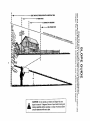
SLOPE GUIDE ........................................................ 31
PARTS ORDERING/SERVICE ................. Back Page
ON
For one year from the date of purchase,when this Chipper Vac is maintainedand lubricated accordingto the operating
and maintenanceinstructionsinthe owner'smanual, Searswillrepairany defectin materialor workmanshipfree ofcharge.
If this Chipper Vac is used for commercial or rental purposes,this warranty applies for only 90 days from the date of
purchase.
This warrantydoes not cover repairs necessary because of operator negligence or abuse, including the failure to maintain
the equipment according to instructions contained in the owner's manual.
WARRANTY SERVICE IS AVAILABLE
IN THE UNITED STATES.
BY CONTACTING
THE NEAREST
SEARS SERVICE CENTER/DEPARTMENT
This warranty applies only while this productis in the United States.
This warranty gives you specific legal rights, and you may also have other rights which vary from state to state.
Sears, Roebuck and Co. D/817 WA. Hoffman Estates, Chicago, IL 60179
The model number and serial numbers will be found on a
decal attached to the Chipper Vac.
You should record both the senal number and the date of
purchase and keep in a safe place for future reference.
MODELNUMBER:
SERIALNUMBER:
DATE OFPURCHASE:
486.24515
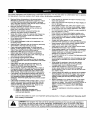
Any power equipment can cause injury if operated improperly or if the user does not understand how to operate
the equipment. Exercise caution at all times, when using power equipment.
•
•
•
•
•
•
•
•
•
•
•
•
•
•
•
•
Read and follow all instructionsin this manual before
attempting to assemble or operate this equipment. Failure
to comply with these instructions may result in personal
injury. Keep this manual in a safe place for future reference
and for ordering replacement pads.
Reed this operating and service instruction manual
carefully. Be thoroughly familiar with the controlsand
proper use of this power vacuum.
Read the vehicle owners manual and vehicle safe
operation rules before using this equipment.
Never allow children under 16 to operate this Chipper Vac.
Children 16 years and older should only operate under
close parental supervision.
Do not allow anyone to operate this equipment without
proper instructions.
Do not allow passengers to ride on this equipment or on
the towing vehicle.
Keep the area of operationclear of all persons, particularly
small children, Also keep area clear of pets.
Check fuel before starting engine, Do not fillfuel tank
indoors, or when engine is running, or while engine is hot.
Wipe off any spilledfuel before starting engine.
Engine and muffler get hot. Do nottouch!To avoid fire
hazard, keep cleanof debris and other accumulations,
Never store Mow-N-Vac with fuel in tank. Allow engine to
coot before storing in any enclosure.
Do not change engine governor settings.
Do not operate engine if air cleaner or cover is removed,
except for adjustment. Removal of these pa,_scould create
a fire hazard.
Keep hands, feet, face, long hair and clothing out of
chipper inlet, vac inlet and discharge area. There are
ROTATING BLADES inside these openings.
Before cleaning, repairing or inspecting,make certain all
moving parts come to a complete stop. Disconnect spark
ptugwire and keep wire away from plug to prevent accidental starting. Keep throttlecontrol lever in stop position.
If the Chipper Vac should become blocked with debris at
any point, shut engine off and wait until the impetler comes
to a complete stop before attempting to remove the
obstruction.Disconnect spark plug wire to prevent accidental starting.
If the cutting mechanism strikes a foreign object, or if your
ChipperMac shouldstart to vibrate abnormally, stop the
engine immediately, disconnectthe spark plug wire and
move the wire away from the spark plug. Allow the machine to stop and take the following steps.
a. Inspect for damage.
b. Repair or replace any damaged parts.
c. Check for loose parts and tighten to assure
continued safe operation.
•
Check all bolts for tightness at frequent
insure safe operation.
•
Check vinyl hard top boot frequently
worn or damaged.
•
Never operate Chipper Vac unless deck adapter, hose,
hose adapter (nozzle), discharge chute (elbow), chipper
chute and top cover are properly attached in their place.
•
Do not remove top cover or attempt to empty contents of
cart while engine is running.
•
Never attempt to change hose adapter (nozzle) or to
install remote hose attachment when engine is running.
•
Keep all shields and guards (e.g. chipper chute, discharge
chute (elbow) and hose adapter (nozzle) in place and
securely attached.
•
Always wear safety glasses or other suitable eye
protection when operating or maintaining this equipment.
Wear protective gloves when feeding material into the
chipper chute. Avoid loose fitting clothing.
Keep face and body clear of the chipper chute to avoid
accidental bounce back of any material.
•
•
for wear.
to help
Replace
if
•
When feeding material into this equipment, be extremely
careful that pieces of metal, rocks bottles, cans or other
foreign objects are not incJuded. Personal injury or
damage to the machine could result.
•
DO not stand behind cart in exhaust discharge area while
engine is running.
Do not operate this equipment while intoxicated or while
taking drugs or medication
that impairs the senses and
reactions.
•
•
When using this equipment, start with the vehicle
transmission in first (low) gear and then gradually
increase speed only as conditions permit.
•
Operate this equipment at reduced speed on rough
terrain, along creeks and ditches and on slopes to
prevent tipping or loss of control. Do not drive too close
to a creek or ditch.
•
Vehicle braking and stability are affected by the addition
of this equipment. Do not fill the Chipper Vac to its full
capacity without checking the capability of the towing
vehicle to safely pull and stop with the Chipper Vac
attached.
•
Before operating on any grade (hill) refer to the safety
rules in the vehicle owner's manual concerning safe
operation on slopes. Also refer to the SLOPE GUIDE on
page 31 of this owner's manual. Do not operate on
slopes in excess of 10 degrees. STAY OFF STEEP
SLOPES.
•
Follow the maintenance
manual.
Look for this symbol to point out important safety precautions.
Your safety is involved.
&
intervals
instructions
It means--Attention!!
outlined in this
Become alert!!
I
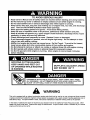
DANGER:
This Chipper Vac was built to be operated according
this manual. As with any type of power equipment, carelessness
tot can result in serious injury. This unit is capable of amputating
objects. Failure to observe the following safety instructions could
to the rules for safe operation in
or error on the part of the operafingers and hands and throwing
result in serious injury or death.
I
I
TO AVOID SERIOUS INJURY
Read Owner's Manual and all safety labels on machine before starting and using machine.
Do Not remove top cover or attempt to empty contents of cart while engine is running.
Do Not stand behind cart in exhaust discharge area while engine is running.
Keep hands, feet, face, long hair and clothing out of chipper inlet, vac inlet, and discharge
area. There are ROTATING BLADES inside these openings.
Wear approved safety glasses and gloves. Avoid loose fitting clothes.
Keep the area of operation clear of all persons, particularly small children and pets.
Keep all shields and guards (e.g. upper chipper chute extension, discharge chute, nozzle
assembly) in place and securely attached.
Check discharge boot frequently for wear. Replace if worn or damaged.
If unit becomes clogged or jammed, shut off engine right away. Do Not attempt to clear
clog or jam with engine running.
Muffler and engine get hot and can cause burns. Do Not Touch. To avoid a fire hazard,
keep leaves, grass and other combustible debris off hot muffler and engine.
Do Not attempt to remove or attach vac nozzle or optional Hose Kit with engine running.
Do Not operate unit unless nozzle or optional Hose Kit is secured in place.
Do Not fill gas tank while engine is running. Allow engine to cool at least 2 minutes
before refueling.
ROTATING CU'I-FING BLADES.
KEEP HANDS AND FEET OUT
OF OPENINGS WHILE MACHINE
&
MUFFLER & ADJACENT
MAY EXCEED 150 o F
AREAS
WARNING
This unit is equipped with an internal combustionengine and should not be used on or near unimproved forest-covered,
or grass-covered land unless the engine's exhaust system is equipped with a spark an'ester meeting applicable local or
state laws (if any). If a spark arrester is used, it should be maintained in effectiveworking order by the operator.
In the State of California the above is required by law (Section 4442 of the California Public Resources Code). Other
states may have similar laws. Federal laws apply on federal lands. A spark arrester muffler is available at you nearest
engine authorized service center.
SHOWN
FULL SIZE
A
NOT SHOWN
P
Q
V
FULL SIZE
W
_/X
Y
AC
AB
%
AD
G
AE
AF
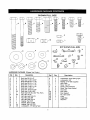
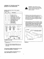
HARDWARE PACKAGE (ChipperVac Carton)
Ref.
A
E
C
D
E
F
G
H
I
J
K
L
M
N
O
P
Q
R
Qty.
3
4
5
2
1
2
2
6
28
4
38
9
5
1
1
6
24
36
Description
Bolt, Hex 3/8-16 x 3"
Bolt, Hex 1/4-20 x 2-3/4"
Bolt, Hex 3/8-16 x 1-1/2"
Bolt, Hex 3/8-16 x 1-1/4"
Bolt, Hex 1/2-13 x 1-1/4"
Bolt, Hex 1/4-20 x 1-1/4"
Bolt, Hex 1/4-20 x 1"
Bolt, Hex 5/16-18 x 3/4"
Bolt, Hex 1/4-20 x 3/4"
Bolt, Hex 5/16-18 x 3/4" Thd. Form.
Nut, Hex 1/4-20
Nut, Hex Lock 5/16-18
Nut, Hex Lock 3/8'
Nut, Hex Lock 1/2-13
Washer, Fiat 7/16"
Washer, Nylon 21/64"
Washer, Rat 1/4" STD
Lockwasher, 1/4" Spring Type
Ref.
S
T
U
V
W
X
y
Z
AA
AB
AC
AD
AE
AF
Qty.
4
5
3
1
1
5
2
2
2
2
1
3
1
1
Description
Lockwasher, 5/16" Spring Type
Lockwasher,3/8"
Washer, 5/16" Bell (cupped)
Hitch Plate
Strap, Tarp 25"
Clamp, Cart Extension
Strap, Tarp (Less Hooks)
Hook #32
Door Latch
Door Support
Pin, Hair Cotter
Knob
Angle Stop
Hitch Pin
Ref.
SHOWN
FULL SIZE
F
A
B
C
Qty.
)°
E
F
G
H
j /D
I
14
25
2
27
14
4
2
2
2
Description
Sit. Truss Hd. Bolt, 5/16" x 3/4"
Hex Bolt, 1/4" x 1/2"
Hex Bolt, 1/4" x 1-3/4"
Hex Nut, 1/4-20 Thread (SEMS)
Hex Nut, 5/16-18 Thread (SEMS)
Flat Washer, 1"
Cotter Pin, 1/8" x 1-1/2" Lg.
Hub Cap
Spacer Tube, 2" Lg.
Bag contains extra 1/4" x
1/2" bolts and 1/4" nuts
Not Shown Full Size
G
r
i
HARDWARE PACKAGE (Cart Body Carton)
_1
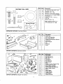
CARTON
_
CONTENTS
_6
9
CONTENTS
Description
1
2
3
2
1
1
Corner Cap
Latch Lock Assembly
Latch Stand Bracket
4
5
1
1
Tailgate Reinforcement
Front Panel
6
7
1
1
Wheel Support
Axle
8
9
2
2
Cart Body
Wheel
Ref.
1
2
3
4
5
6
7
8
9
10
11
12
13
14
15
16
17
18
19
Qty.
1
1
1
1
1
1
1
1
1
1
1
• 1
1
1
2
1
1
1
1
Bracket
(Cart Body Carton)
O
CARTON
Ref. Qty.
(Chipper
Vac Carton)
6
Description
Front Panel
Side Panel (R.H.)
Side Panel (L.H.)
Rear door
Cross Brace
Poly Hard Top
Deck Adapter
Elbow
Chipper Chute w/Tamper Plug
Hose Adapter (Nozzle)
Engine Base Assembly
Hose Hanger Rod Assembly
Hose Hanger Bracket
Hose
Hose Clamp
Tongue (Rear)
Tongue (Front)
Hitch Bracket
Adapter Bracket
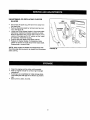
This unit is shipped WITHOUT GASOLINE or OIL. After
assembly, see separate engine manual for proper fuel
and engine oil recommendations.
•
TOOLS REQUIRED FOR ASSEMBLY
(1)
(1)
(2)
(2)
(2)
Screwdriver
Pliers
7/16" Wrenches
1/2" Wrench
9/16" Wrenches
(2)
3/4" Wrenches (only if figure 24 on page 14 is used)
REMOVAL
•
•
OF PARTS
CARTON
1/4" x 1/2"
. HEX BOLT
THE CHIPPER
*_'" "'_'_/
5116"x 3/4"
._-,_"
SLO'I-FED BOLT
VAC
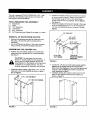
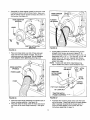
Position cart body halves upright on a smooth level
surface such as a garage floor or a paved driveway.
See figure 1.
&
•
FROM
1/4" HEX NUT
Remove the hardware pack and all loose pars from
the carton. Be sure the carton is empty before
discarding.
Lay out atl the pars as shown in the carton contents,
Keep contents of hardware packages separated.
ASSEMBLING
•
•
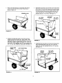
Position the tailgate reinforcement bracket on outside
of cart as shown in figure 2. Fasten to the bottom of
the cart body using six 5/16" x 3/4" slotted head
screws and 5/16" hex nuts (SEMS). Do not tighten.
See figure 2.
Fasten the tailgate reinforcement bracket to the sides
of the cart body using four 1/4" x 1/2" hex bolts and
1/4" hex nuts (SEMS) as shown in figure 2. Do not
tighten.
CAUTION: Do not leave the cart unattended in upright position during assembly. A
falling cart can cause personal injury! Pay
close attention to the stability of the cart while
it remains in an upright position. For best
stability, assemble on a smooth level surface.
Assemble halves together using three 1/4" x 1/2" hex
bolts and 1/4" hex nuts (SEMS) as shown in figure 1.
Do not tighten.
1/4" x 1/2" HEX BOLT
5/16" HEX
NUT (SEMS)
TAILGATE
REINFORCEMENT
BRACKET
FIGURE 2
•
•
At this time, with the cart body halves pulled together,
tighten the sixslotted head screws assembled in
figure 2 and then tighten the four hex bolts assembled
in figure 2. Do not tighten the three hex bolts that
were assembled in figure 1.
Carefully reverse the position of the cart so that it
rests on the tailgate reinforcement bracket, as
shown in figure 3.
1/4" HEX NUT (SEMS)
o
o
•
d
)
FIGURE 1
FIGURE 3
Assemble the front panel over the end of the cart
using six 1/4" x 1/2" hex bolts and 1/4" hex nuts
(SEMS) as shown in figure 4. Leave two holes open
in the bottom of the panel as shown in figure 4. With
the cart body halves pulledtogether, tighten the four
bolts in the bottom of the front panel, then tighten the
bolt in each side.
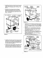
Assemble the latch stand bracket to the cart using
four 1/4" x 1/2" hex bolts and 1/4" hex nuts (SEMS).
TIGHTEN. See figure 6.
LATCH STAND BRACKET
1/4" x 1/2"
HEX BOLT
\
At this time tighten the three bolts on the bottom of
the cart which were assembled in figure 1.
LEAVE HOLES OPEN FOR
LATCH STAND BRACKET
1/4" x 1/2"
HEX BOLTS
1/4" HEX NUT (SEMS)
FIGURE6
1/4" HE](
NUT (SEMS)
1/4" HEX
NUT (SEMS)
FIGURE 4
To prevent accidental tipping during the following
assembly procedures, lower the cart to rest upside
down on the top flanges, so that the wheel support is
facing up as shown in figure 7.
Assemble the wheel supportto the bottom of the cart
using eight 5/16" x 3/4" slottedhead screws and
5/16" hex nuts (SEMS) as shown in figure 5. Heads of
screws go to the inside of cart. Tighten.
SLO'n'ED SCREW
5/16" x 3/4"
WHEEL
SUPPORT
\
FIGURE
5/16" HEXNUT (SEMS) _
FIGURE 5
7
•
Assemble the front tongue over the top of the rear
tongue using three 3/8" x 3" hex bolts, 3/8" lock
washers and 3/8" hex lock nuts. See figure 8.
Position the tongue on the bottom of the cart as
shown in figure 11. Assemble the axle through the
wheel support and the tongue. Fasten the axle to
the wheel support using two 1/4" x 1-3/4" hex bolts
and 1/4" hex nuts (SEMS). Tighten.
(3)3/8" x 3"
TONGUE
_,/HEX
(REAR)
_
BOLTS
IMPORTANT: Make sure the tongue is securely locked
to the latch stand bracket by the latch lock assembly.
TONGUE
1/4" x 1-3/4"
HEX BOLT
(3)
WASHERS
_'-_-.-.
AXLE
(3) 3/8" HEX
LOCK NUTS
"_
(DRAW BAR)
FIGURE 8
•
Assemble the hitch bracket to the front tongue using "'
two 3/8" x 1-1/4" hex bolts, 3/8" lock washers and 3/8"
hex nuts. Tighten. See figure 9.
3/8" x 1-1/4"
_
HEX BOLT "'"_1
HITCH BRACKET
/
TONGUE
..
.
3/8
LOCK
_"_I_
TONGUE
WAS H ER _..._........_
NUT---_
LOCK
FIGURE
•
•
114" HEX
NUT
(SEMS)
/
FIGURE 11
9
Assemble the latch lock assembly to the tongue using
two 1/4" x 2-3/4" hex bolts, two 1/4" lock washers and
two 1/4" hex nuts. Fasten to the two front holes in the
forward grouping of four holes as shown in figure 10.
Assemble the angle stop to the tongue using two 1/4"
x 2-3/4" hex bolts, two 1/4" lock washers and two 1/4"
hex nuts. Fasten to the two front holes in the rear
grouping of four holes as shown in figure 10.
HE)( BOLT
•
•
Assemble a spacer tube onto each end of the axle as
shown in figure 12.
Assemble a flat washer, a wheel (valve stem facing
out), and another flat washer onto the axle as
shown in figure 12. Secure the wheel with a cotter
pin, spreading the ends so that a hub cap can fit
over the pin. Assemble the hub cap by pressing it
onto the flat washer. Repeat on other end of axle.
SPACER TUBE
LATCH LOCK
ASS'Y.
ANGLE
TONGUE
WHEEL
FLAT
WASHER
\
1/4" LOCK
WASHER
WASHER
FLAT
WASHER
t
HUB CAP
1/4" HEX
NUT
FIGURE
10
FIGURE
12
CoI-rER PIN
•
Set the cart right side up on its wheels and place a
corner cap over each front corner of the cart as
shown in figure 13.
CORNER
AssembLe front panel over the ends of the side panels
and on top of the cart bed flange and the comer caps.
Leaving the top holes in the front pane{ empty, fasten
it to the cart body and the side panels using six 1/4"
x 3/4" hex bolts, six 1/4" flat washers, six 1/4" lock
washers and six 1/4" hex nuts. See figure 15.
CAPS
1/4" LOCK
WASHER
1/4" FLAT
WASHER
1/4" x 3/4"
HEX BOLT
FIGURE 13
FRONT
PANEL
Positionthe right side panel on top of the cart bed
flange and the front comer cap. Align holes in side
panel with holes in corner cap and holes in top of cart
bed flange. Fasten together using two 1/4" x 3/4" hex
botts, two 1/4" flat washers, two 1/4" lock washers and
two 1/4" hex nuts. Repeat on other side. See figure 14.
RIGHT SIDE
PANEL
FIGURE 15
•
Assemble the cross brace to the two top holes at the
rear of each side panel using four 1/4" x 3/4" hex
bolts, four 1/4" lock washers and four 1/4" hex nuts.
See figure 16.
LEFT SIDE PANEL
1
CROSS
BRACE
1/4" HE)( NUT
1/4" LOCK
WASHER
1/4" HEX NUT
FIGURE 14
FIGURE 16
10
1/4" x 3/4"
HEX BOLT
I
Installthepolyhardtopoverthefrontandsidepanels.
Fastenusingfourteen
1/4"x3/4"hexbolts,1/4"flat
washers,
1/4"lockwashers
and1/4"hexnuts.See
figure17.
5/16" HEX
LOCKNUT
NYLON
WASHER
CROSS
BRACE
Assemble the five clamps onto the cart flanges,
placing one in f_ont center and two on each side,
positioned approximately 12" from each end. Use a
3/8" x 1-1/2" hex bolt to secure each clamp from the
bottom. See figure 17.
•5/16" x 3/4 •
HE)( BOLT
POLY HARD TOP
1/4" HEXNUT
1/4"LOCK
WASHER
BOLT
DOOR
BRACKET
; -HEXNUT
FIGURE 18
•
CLAMP
CLAMP
3/8" x 1-1/2"
•
FRONT
•
FIGURE 17
Assemble one short tie strap to each side of rear door
using one 1/4" x 1-1/4" hex bolt, two 1/4" fiat washers,
one 1/4" lock washer and one 1/4" hex nut. Assemble
an "S" hook through the loose end of each strap. See
figure 19.
Assemble a 1/4" x 1" hex bolt with a 1/4" hex nut to
outside of hole on each side of cart bed and secure
from inside with a 1/4" lock washer and a 1/4" hex
nut. See inset in figure 19.
Assemble door to rear of cart by resting bottom of
door on door support brackets and rotaUng top of door
forward to meet cross brace. Latch top of door on
each side. See figure 19.
Hook both the fie straps onto the 1/4" x 1• hex bolts
which were just assembled. See figure 19.
._CROSS
Assemble a door latch at each end of the cross brace
using a 5/16" x 3/4" hex bolt, a nylon washer and a
5/16" hex lock nut. Place nylon washer between door
latch and cross brace. Tighten so that latch is snug
but will still rotate. See figure 18.
BRACE_.
, _ ,,
_f
"_,;1/4"'FLJ_T_-_'_?
Assemble door support brackets underneath the rear
of the cart bed by removing the hex nuts from the
bolts shown in figure 18. Fasten the brackets to the'
cart using the same hex nuts which were removed.
STRAP
.....
1/4 xl
' --'_ ""
T"'_"-'_I/4
DOOR
t_" _,
HEX BOLT
LOCK
1/4
• FLAT
; ,, WASHOR
HEX NUT
FIGURE
11
19
""_u-_1/4" LOCK WASHER
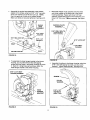
Mount the chipper chute assembly onto the three
weld bolts located on the back side of the blower
housing assembly. Fasten with three 5/16" bell
washers (cupped side against chute assembly) and
three 5/16" lock nuts. Tighten securely. See figure
22.
Assemblethe engine base assembly to the welded
angles on the tongue using four 5/16" x 3/4" hex bolts,
5/16" lock washers and 5/16' hex lock nLRs. NOTE:
Use the upper set of holes in the welded angles.
Make sure bolts are securely tightened. See figure 20.
CHIPPER CHUTE
ASSEMBLY
ENGINE
BASE
5EMBLY
5/16" WELD BOLTS
,
(FOUND ON BACK
5/16" LOCK
WASHER
I'
5/16" HEX LOCK NUT------.._
16" x 3/4"
HEX BOLT
RF.AR
/
l
.--'"_'_
5/16" LOCK NUT
5116" BELL
WASHER
WELDEDANGLES
FRONT
i
FIGURE 20
'FIGURE22
To assemble the hose hanger bracket to the blower
housing,you mustfirst remove two self tapping
screws from the holes in the blower housing as shown
in figure 21. Using these same screws, attach the
hose hanger bracket to the blower housing.
•
Assemble the eibow to the blower housing, using four
5/16" x 3/4' self tapping hex bolts, and four nylon
washers. Tighten bolts securely. See figure 23.
5/16" x 3/4" SELF
TAPPING SCREWS
NYLON
WASHER
HOSE
HANGER
BRACKET
5/16" x 3/4"_
(SELF TAP)
HEXBOLT [
FIGURE 23
FIGURE 21
12
• Assemble
thehoseadapter
(nozzle)
to the front of the
housing and secure with the three knobs, Make sure
that the switch actuator bracket contacts the switch on
HOSE HANGER
ASSEMBLY
the housing. See figure
24_
HOSEAOAPTER
(NOZZLE)
RUBBER
TIE STRAP
/_F--"-'o
SWITCH ACTUATOR
BRACKET
_,
FIGURE 26
FIGURE 24
•
A hitch plate is furnished for tractors having square
(straight) hitch frames, as shown in figure 27, to
prevent binding of Mow-N-Vac hitch in tight turns. It is
assembled with a 1/2" x 1-1/4" hex bolt, a 7/16" flat
washer and a 1/2" lock nut. Tapered hitch frames,
shown at the bottom of figure 27, do not require the
added hitch plate.
NOTE: Tractors with light (thin) metal &ames may
require added hitch plate to avoid excessive wear.
Place one hose clamp over end of hose and push
hose onto the hose adapter (nozzle). Secure by
tightening screw on hose clamp. Do not collapse
hose adapter when tightening. See figure 26.
HOSE ADAPTER
1/2" x 1-1/4"
HEX BOLT
(NOZZLE)
HOSE CLAMP
TRACTOR
HITCH FRAME
HITCH
PIN
1
(SQUARE)
HITCH
PLATE
HOSE
HAIRPIN
i/,
7/16.
FLAT WASHER
,j,,_
COTTER
_, I ,_,
1/2" LOCK NUT
TRACTOR HITCH
FRAME (TAPERED)
•
_..- ._
_
",
'
. ""
_;.::'
FIGURE 27
FIGURE 25
•
"
Place the hose hanger assembly into welded tube on
blower housing assembly. See figure 26.
Wrap the rubber tie strap under the hose and secure
the hooks to the hose hanger assembly. See figure
26.
Assemble the remaining hose clamp over the loose
end of the hose. Fasten the hose to the deck adapter
after it has been mounted to the mower deck. To
mountthe deck adapter to the mower deck see
instructionsbeginningon page 14.
13
ASSEMBLY
(#62468)
OF THE DECK ADAPTER
TO THE
MOWER
Contents of Hardware
See Figure 28.
Key
Qty.
A
B
C
D
E
F
G
H
I
d
K
2
3
2
3
3
3
12
3
1
1
1
DECK
CAUTION: Mower deflector must be
replaced when Mow-N-Vac deck adapter
is removed. Do Not operate mower unless
adapter or deflector is in place and
properly mounted.
&
Pack for Deck Adapter:
Description
Hex Bolts, 5/16" x 1"
Hex Bolts, 1/4" x 3/4"
Carriage Bolts, 5/16" x 3/4"
Hex Lock Nuts, 5/16-18 Thread
Hex Lock Nuts, 1/4-20 Thread
Fiat Steel Washers, 1/4" Std.
Flat Washers, 5/16" Std.
Nylon Washers, 21/64
Mounting Strap
Angle Bracket
Mounting Bracket
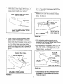
Identi_ your mower deck (see fold outs) and cut out
the correct discharge opening template for your
mower deck size. If there is no template for your deck
size you can make your own template by marking
around a piece of cardboard held against the edge of
the discharge opening.
Tape the template to the face of the adapter, locating
template approximately 1/2" from front and 1/4" down
from top of adapter. Keep as close to top as possible.
See figure 29. Mark outline of template on face of
adapter usingwhite crayon, nail or scriber. Drill a
starting hole inside the outline, then use a saber saw
or key hole saw to cut out the opening. See figure 29.
1/4" DOWN
IMPORTANT:
F
NOT SHOWN FULL SIZE
I
j
1/2" FROM FRONT
FIGURE 28- FULL SIZE
NOTE: Not all of the hardware will be used for any one
particular fit up.
•
FIGURE 29
Remove the mower discharge deflector from your
mower deck. Save the deflector and hardware for
remounting.
IF YOU HAVE A MURRAY TRACTOR WITH A 38" OR
40" DECK, SKIP DIRECTLY TO PAGE 16.
IF YOU HAVE A MURRAY TRACTOR WITH A 46"
DECK, SKIP DIRECTLY TO PAGE 16.
14
Keep cut-off as close to
the top edge as possible.
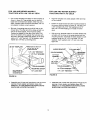
Position the adapter over the deck opening, and check
for fit of cutout as shown in figure 30. Trim cutout, if
necessary, to allow tilting of adapter, keeping the fit as
close as possible for best vacuum suction.
•
Assemble the adapter bracket to the deck using two
5/16" x 1" hex bolts, 5/16" fiat washers and 5/16" lock
nuts. See figure 32.
NOTE: It may be necessary to use extra 5/16" flat
washers to shim under the bracket next to the deck
surface. Ten extra washers have been furnished as
shims, See figure 32.
NOTE: Make sure adapter clears gauge
wheels on mower deck
°.o,o,
,'
i
ADAPTER
Curl on deck may be located outside of
adapter or inside depending on deck
opening design
.( 2 ) 5/16" LOCK NUTS
®/
'_-_
_(21
-_.._
_
5/16" FLAT
WASHERS
BRACKET
5/16" x 1' HEX BOLT jf_
FIGURE 30
5/16" flat washers
used as needed for
shims to adjust for
variations In decks,
FIGURE 32
•
Holding the adapter bracket and the deck adapter
together, position the deck adapter on the mower
deck. Keeping the edge of deck adapter as close as
possible to the offset in the adapter bracket, see if the
slot in the adapter bracket can be aligned with one or
two of the deflector holes in your mower deck's
discharge opening. If the bracket can not be located
correctly using existing holes, it will be necessary to
drill one or two 5/16" diameter holes in the deck. See
figure 31.
With deck adapter positioned correctly over the
discharge opening, use the adapter bracket as a
template and drill three 9/32" diameter holes in the top
of the deck adapter. See figure 33.
Bolt deck adapter to bracket using three 1/4" x 3/4"
bolts, nylon washers, 1/4" flat washers and 1/4" lock
nuts. Nylon washers should be against the inside of
the deck adapter. See figure 33.
DECK ADAPTER
Use existing holes or drill 5/16"
diameter hole or holes,
(3) t/4- H£X
LOCK NUTS
ADAPTER BRACKET
ADAPTER
BRACKET
(3) NYLON
WASHERS
_)I_"STEEL
MOWER DECK
WASHERS
_)1_'x3/4"
DECK ADAPTER
HEXBOLTS
FIGURE 33
MOWER DECK
•
Keep edge of adapter as close
as possible to offset in bracket
FIGURE 31
15
Assemble end of hose and a hose clamp over the
round opening of deck adapter and tighten clamp.
GO DIRECTLY TO THE OPERATION INSTRUCTIONS ON PAGE 17.
FOR 1990 AND NEWER MURRAY
TRACTORS
WITH A 38" OR 40" DECK
FOR 1990 AND NEWER MURRAY
TRACTORS
WITH A 46" DECK
Cut out two templates and place on deck adapter as
shown in figure 34. Tape smaller one on top and
larger one on the side and bottom. After they are in
place, carefully mark around the templates, then cut
out adapter to obtain correct opening.
•
Fasten the angle bracket and the mounting bracket to
the mower deck as shown in figure 35. Use two 5/16"
x 3/4" carriage belts, 5/16" flat washers and 5/16"
lock nuts. The bolt heads go on inside of mower
deck.
Bolt end of mounting strap to the 5/16" bolt on the
mower deck. The other end of the strap will bolt to a
hole in the deck adapter, which must be drilled.
Position the adapter on the deck, then drill a 5/16"
hole in the bottom of the adapter that will align with
the hole in the strap. Fasten the adapter to the strap
using a 1/4" x 3/4" hex bolt, 1/4" fiat washer, nylon
washer and 1/4" hex nut. See figure 34.
38"/40" TEMPLATE
Tape 46" template onto deck adapter. Mark and then
cut out adapter.
Drill two 5/16" diameter holes in the deck adapter that
will align with the holes in the angle bracket and the
mounting bracket. Assemble the deck adapter to both
brackets using two 1/4" x 3/4" hex bolts, 1/4" flat
washers, nylon washers and 1/4" lock nuts. See
figure 35.
TEMPLATE TO CUT OUT SLOT
CUT OUT SLOT IN TOP
OF DECK ADAPTER
\.
ANGLE BRACKET
1/4" x 3/4" HE_ BOLT
NYLON WASHER
1/4" FLAT WASHER
_
/
MOUNTING
1/4" FLAT
1/4" x 3/4"
NYLON WASHER
_IYLONWASHER
"MOUNTING STRAP
BOLTTHIS END OF
STRAP TO 5/16" BOLT
ON MOWER DECK
1/
1/4" LOCK NUT
1/4" x 3/4" HEX BOLT-_-,--%_
FIGURE 35
FIGURE 34
•
Assemble end of hose and hose clamp over the round
opening of deck adapter and tighten clamp. GO
DIRECTLY TO THE OPERATION INSTRUCTIONS
WHICH ARE LOCATED ON PAGE 17,
Assemble end of hose and hose clamp over the round
opening of deck adapter and tighten clamp. GO
DIRECTLY TO THE OPERATION INSTRUCTIONS
WHICH ARE LOCATED ON PAGE 17.
16
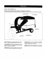
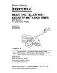
KNOW YOUR
CHIPPER
VAC
Read this owner's manual and safety rules before operating your Chipper Vac.
Compare the illustrationbelow with your Chipper Vac to familiarize yourselfwith the various controlsand their locations.
HARD TOP BOOT
PLUG TAMPER
TARP STRAP
LATCH LOCK
HARD TOP BOOT Connects the plastic elbow to the
hard top, directing discharged material into the cart.
CHIPPER CHUTE
CHIPPER CHUTE Used to hand feed yard vegetation,
including branches up to 3" in diameter, into impeller
housing for chipping and shredding.
PLUG TAMPER Fits down into the chipper chute as a
guard when not in use. Pushes material down into the
chute for chipping and shredding.
LATCH LOCK Locks the cart bed down to the tongue.
Releases to allow cart to be tipped back for dumping.
TARP STRAP Hooks onto the side of the cart to hold
the rear door securely up against the rear of the cart.
17
BEFORE
•
•
•
STARTING
HOW TO USE YOUR
Your Chipper Vac engine is shipped withoutoil or
gasoline. Service the Chipper Vac engine with oil and
gas as instructed in the separate engine manual.
Inspect the Chipper Vac to make sure all covers (rear
door, hard top boot, elbow, hose adapter, hose and
deck adapter are property attached.
Check tires for proper inflation (12 - 14 Ibs).
&
•
with
the engineNever
running,
or while
engine
WARNING:
fill fuel
tank the
indoors,
or
is hot. Do not smoke while filling tank.
•
•
•
HOW TO STOP YOUR CHIPPER
VAC
• To stop engine, move the throttle control lever to the
OFF position.
• Disconnect spark plug wire from plug to prevent
accidental starting while equipment is unattended or
is being worked on.
•
•
•
•
CHIPPER
VAC
CAUTION:
Vehicle braking and stability
may be affected withthe addition of an
accessory or an attachment. Be aware of
changing conditions on slopes.
Inspect the Chipper Vac to make sure all covers (rear
door, hard top boot, elbow, chipper chute with tamper
plug, hose adapter (nozzle), hose and deck adapter
are properly attached.
Check tires for proper inflation(12 - 14 Ibs).
Check oil and gas in Chipper Vac engine.
Begin operation at low speed, adjusting forward
speed to match grass height and/or moisture condition to prevent clogging.
Do not attempt to vacuum up any material other than
vegetation found in a normal yard, such as light
branches, leaves, twigs, etc.
To empty cart, shut off tractor engine and set
brake.
Shut off Chipper Vac engine.
Remove rear door from cart.
CAUTION:
areas
are holtThe muffler and adjacent
sure that no one is near the cart before
CAUTION: To avoid possibleinjury, be
releasing the latch.
HOW
TO START
YOUR
CHIPPER
VAC
•
i_
•
•
•
•
•
•
•
•
engine withoutNever
all covers
WARNING:
start being
or runproperly
the
attached to the blower housing and cart.
•
Check oil and gas in Chipper Vac engine.
Attach spark plug wire to spark plug.
Move choke lever on engine to CHOKE position.
(A warm engine may not require choking.)
Move throffle control lever on engine to FAST position.
Grasp starter handle and pull rope out slowlyuntil
engine reaches start of compression cycle (rope will
pull stightly harder at this point). Let the rope rewind
slowly.
Pull rope with a rapid, continuous, full arm stroke.
Keep a firm grip on starter handle. Let rope rewind
slowly. Do not let starter handle snap back against
starter.
Repeat instructions in two preceding paragraphs until
engine fires. When engine starts, move choke control
gradually to RUN position.
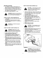
Release the latch holding cart down to the tongue by
pulling up on the latch lever. See figure 36.
Using a rake or suitable tool, pull the grass clippings
and/or leaves out of cart.
After cart is emptied, secure cart to tongue with
latch and reattach the rear door and the hard top
boot.
1
FIGURE 36
&
18
WARNING:
Should your Chipper Vac
become clogged, shut off tractor and
Chipper Vac engines. Before attempting
to unclog, remove wire from spark plug to
prevent accidental starting.
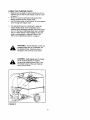
USING THE CHIPPER CHUTE
• Material such as stalksor heavy branches up to 3" in
diameter may be fed intothe chipperchute as shown
in figure 37.
• Be sure to wear eye protection and gloves when
feeding material into the chipper chute.
• Use the tamper plug, not your hands, to force material
down through the chipper chute.
For best performance, it is important to keep the
chipper blades sharp. If the compositionof the
material being discharged changes (becomes stnngy,
etc.) or if the rate of discharge slows down considerably, it is likelythat the chipper blades are dull and
need to be sharpened or replaced. Refer to the
Service and Adjustments section, on page 21.
&
WARNING:
Do not attempt to feed an_i
material larger than 3" in diameter into
the chipper chute. Personal injury or
damage to the machine could result.
&
DANGER: Keep hands out of chipper
chute. Rotating blades in impeller
housing can cause serious injury. Use
the tamper plug to help push material
clowninto the chute.
FIGURE 37
19
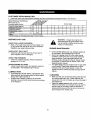
CUSTOMER
RESPONSIBILITIES
Read and follow the maintenance schedule and the maintenance procedures listed in this section.
i MAINTEN AN C ES C HEDULE
_'__o_J
Fill
in dates
as you
complete
regular
service.
_,_'_
/,"_'_.,_,,,,_
Check for loose fasteners
X
Check soft vinylboot
Check tire pressure
Check enoin_oil level
X
X
X
Lubricate
Clean
X
Maintain enoine oer instructions
BEFORE
EACH
_o_ =_
ServiceDates
X IX
below and in enoine manual.
USE
&
CHECK FOR LOOSE FASTENERS
• Make a thorough visual check of the Chipper Vac
for any bolts and nuts which may have loosened.
Retighten any loose bolts and nuts.
ENGINE
CHECK SOFT VINYL BOOT
• Check the soft vinyl boot (on front of hard top) for
wear. Replace if worn or damaged.
•
•
CHECK T1RE PRESSURE
•
Check tire pressure regularly. Recommended
pressure is 12-14 Lbs.
CHECK
•
ENGINE
tire
OIL LEVEL
•
Check oil level before each use. Maintain engine oil
as instructed in the separate engine manual.
LUBRICATION
•
•
WARNING:
Always stop engine and
disconnect spark plug wire before cleaning, lubricating or before performing any
repairs or maintenance.
At the beginning of each season, lubricatethe latch,
latch pivot bolt, and the axle where the hitchtongue
pivots,with a lightmachine oil.
At least once a season, grease or oil the wheel
bearings. Use automotive wheel bearing type grease
or 20 weight oil.
MAINTENANCE
Check oil level before each use. Maintain engine oil
as instructed in the separate engine manual
Service air cleaner every 25 hours under normal
conditions.Clean every few hours under extremely
dusty conditions.Poor engine performanceand
flooding usuallyindicatesthat the air cleaner should
be serviced. To service the air cleaner, refer to the
separate engine manual.
The spark plug shouldbe cleaned and the gap reset
once a season. Spark plug replacement is recommended at the start of each season. Check the
engine manual for correctplug type and gap specifications.
CLEANING
•
•
2O
Make sure the cart, the side and front panels and top
are cleaned after each use. Grass clippingsand
leaves left in the cart will mildew and cause damage if
not cleaned out.
Clean the engine regularly with a cloth or brush. "
Keep the coolingfins on the engine housing clean to
permit properair circulationwhich is essentialto
engine performanceand life. Be sure to remove all
dirt and debris from muffler area.
SHARPENING
BLADES
•
•
•
•
•
OR REPLACING
CHIPPER
HEX
LOCK NUTS
Disconnect the spark plug wire and move away from
the spark plug.
Remove the access plate by removingtwo hex lock
nuts. See figure 38.
Locate one of the chipperblades in the access plate
opening by rotating the impellerassembly by hand.
Remove the blade using a 3/16" alien wrench on the
outsideofthe blade and a 1/2" wrench on the impeller assembly, inside the housing.
Remove the other blade in the same manner.
Replace or sharpen blades. If sharpening, make
certain to remove an equal amount from each blade.
Reassemble in reverse order.
NOTE: Make certain the blades are reassembled with
the sharp edge facing upward, as viewed from the access
plate opening.
•
•
•
•
FIGURE 38
Clean the engine and the entire unit thoroughly.
Refer to engine manual for correct engine storage
instructions.
If stohng in an unventilated or metal storage shed,
coat metal parts with light oil or silicone to prevent
rust.
Store unit in a clean, dry area.
21
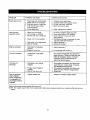
PROBLEM
POSSIBLE CAUSE(S)
CORRECTIVE ACTION
Engine fails to start
1.
2.
3.
4.
Spark plug wire disconnected.
Safe_ switch not contacted.
Fuel tank empty, or stale fuel.
Fuel shut-off valve closed
(if so equipped).
5. Faulty spark plug.
1.
2.
3.
4.
1. Spark plug wire loose
2. Unit running on CHOKE.
3. Blocked fuel line or stale fuel.
1. Connect and tighten spark plug wire.
2. Move choke lever to OFF position.
3. Clean fuel line; fill tank with clean
fresh gasoline.
4.
Disconnect fuel line at carburetor to drain
fuel tank. Refill with fresh fuel
5.
Adjust carburetor.*
6. Service air cleaner.*
Loss of power;
operation erratic.
5. Clean, adjust gap or replace.
4. Water or dirt in fuel system.
5. Carburetor out of adjustment.
6. Dirty air cleaner.
Engine overheats
Too much vibration
Unit does not
discharge
1. Carburetor not adjusted
properly.
2. Engine oil level low.
1. Adjust carburetor.*
2. Fill crankcase
Loose parts or damaged
impeller.
with proper oil.
Stop engine immediately and disconnect
spark plug wire. Tighten all bolts and nuts.
Make all necessary repairs. Lfvibration
continues, have unit servicedby an
authorized service dealer.
1. Discharge chute (elbow)
clogged.
1. Stop engine immediately and disconnect
spark plug wire. Clean inside of housing
and discharge chute (elbow).
2. Stop engine immediately and disconnect
spark plug wire. Remove lodgedobject.
3. Empty cart.
2. Foreign object lodged in
impeller.
3. Mow-N-Vac cart is full.
Rate of discharge
when chipping
slows considerably,
or compositionof
discharged matedal
changes.
Connect wire to spark plug.
Correctly install hose adapter nozzle.
Fill tank with clean, fresh fuel.
Open fuel shut-off valve.
Chipper blades dull.
Sharpen or replace chipper blades.
*Refer to the engine manual packed with your unit.
NOTE: For repairs beyond the minor adjustments listed above, please contact your nearest authorized service
dealer.
22
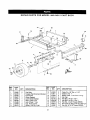
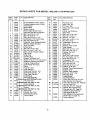
REPAIR
PARTS
FOR MODEL
486.24515
CART
BODY
2
/
14
14
16
3
\
5
6
REF.
NO.
PART
NO.
QTY.
1
2
3
4
5
6
7
8
9
23985
62458
23492
23507
23297
62455
23488
23484
46272
2
1
1
1
1
1
1
2
2
DESCRIPTION
Cart Body
Tailgate Reinforcement
Front Panel
Wheel Support
Latch Stand Bracket
Ass'y, Latch Lock
Axle, Wheel 1" Dia.
Cap, Front Corner
Wheel, 15/6.00 x 8.00
Bracket
REF.
NO.
PART
NO.
10
11
12
13
14
43093
43601
44678
43014
43175
15
16
17
18
1509-69
46978
43814
46980
23
QTY.
2
4
2
2
25
2
27
14
14
DESCRIPTION
Cotter Pin, 1/8" Dia. x 1-1/2"
Washer, Fiat 1"
Spacer Tube, 1-1/4" O.D. x 2" Lg.
Hub Cap
Hex Bolt, 1/4-26 x 1/2" *
Hex Bolt, 1/4-20 x 1-3/4" *
Hex Nut, 1/4-20 Thread (SEMS)
Sit. Truss Hd. Bolt, 5/16-18 x 3/4" Lg.*
Hex Nut, 5/16-18 Thread (SEMS)
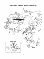
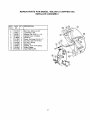
REPAIR
PARTS
FOR MODEL
486,24515
CHIPPER
VAC
4O
41
21
18,19,20,14
\
35,36
I
42
41
28
72
37
/
7
38
54
32
57
/
53
52-
\
17
33
79
83
12
10
/
51
3O
,#
/
58
5
29
30
11':
64
10
66
47
\
ADAPTER
#62468
71
7-/
_s'r
/84
73
24
REPAIR
REF.
NO.
PART
NO.
1
2
3
4
5
6
63025
63155
23475
24080
24078
63226
7
8
9
10
11
12
13
14
15
16
17
18
19
2O
21
22
23
24
25
27
28
29
3O
31
32
33
34
35
36
37
QTY.
PARTS
FOR MODEL
DESCRIPTION
486.24515
REF.
NO.
1
1
1
1
2
1
Tongue Weldment Ass'y. (Rear)
Tongue Weldment Ass'y. (Front)
Hitch Bracket
Engine Base
Brace, Housing
Hose Hanger Bracket Ass'y.
(See also item #23 on page 20.)
43182
18 Bolt, Hex 5/16-18 x 3/4"
43063
4
Bolt, Hex 5/16-18 x 1"
43085
4
Bolt, Hex 5/16-18 x 1-1/2"
43086
16 Lockwasher, 5/16" Spring Type
43064
30 Nut, Hex Lock 5/16-18
63375
1 Assembly, Hose Adapter (Nozzle)
781-0635
1
Bracket, Switch (Actuator)
728-3001
6
Rivet, Pop 5/32"
"
681-0068
1
Chute Ass'y.
43012
5
Bolt, Hex 1/4-20 x 3/4"
43013
10 Nut, Hex Lock 1/4-20 Thd.
63376
1
Ass'y, Chute, Chipper (Upper)
735-0249
1
Flap, Chute
781-0633
1
Strap, Flap
731-1617
1
Tamper, Plug
t520155481 1
Engine, Tecumseh 8 HP
1522-1
2
Screw, #10-12 x 1/2" (not shown)
24097
1
Deflector, Exhaust (not shown)
719-0330A 1
Adapter, Engine Mount
63227
1
Hose Hanger Rod Ass'y.
46420
1
Elbow
43792
1
Hose (6" x 84")
43793
2
Hose Clamp 6"
23834
1
Side Panel Cart Ext. R.H.
23833
1
Side Panel Cart Ext. L.H.
23835
1
Front Panel Cart Ext.
23836
1 Cross Brace
63217
1
Hard Top Assembly
(Incll Ides ems 36,37,38,39,40,41,42.)
46421
1 Top, Poly Hard
(Av= liable only with item no, 35)
23837
1
Screen Support
(Av; liable only with item no. 35)
38
44792
39
40
41
42
(Av= lable only with Item no. 35)
43882
21 Rivet, 3/16"
43910
21 Washer, Fiat 3/16"
23842
4
Boot Mounting Strap
46480
1
Hard top Boot
I 1
Screen
PART
NO.
QTY
43
44
45
46
47
48
49
5O
51
52
53
54
55
56
57
58
60
61
62
63
64
65
66
67
68
69
70
71
72
73
74
75
76
77
78
79
44790
43790
44849
44850
43884
23478
2354O
43012
43661
43088
1509-90
43178
43177
23789
1543-69
23838
43351
43262
43352
23655
43796
43343
43574
43003
43768
43082
43087
43081
24098
43830
23560
43080
23825
23826
23827
46703
8O
81
Y12-0421
_12-301C
3
3
82
F36-024_
3
83
84
25
CHIPPER
1
1
2
2
1
5
1
34
2
36
2
41
36
2
9
2
1
1
1
1
4
1
3
5
5
5
2
12
1
1
1
2
1
1
1
4
1
62468
1
47533
1
VAC
DESCRIPTION
Poly Rear Door
Strap, Tarp 25"
"S" Hook, #32
Strap, Tarp (Less Hooks)
Hitch Pin
Clamp, Cart Extension
Hitch Plate
Bolt, Hex 1/4-20 x 3/4"
Bolt, Hex 1/4-20 x 1"
Washer, 1/4" STD
Bolt, Hex 1/4-20 x 1-1/4"
Nut, Hex 1/4-20
Lockwasher, Spring 1/4"
Door Latch
Washer, Nylon 21/64"
Door Support
Bolt, Hex 1/2-13 x 1-1/4"
NUt, Hex Lock 1/2-13
Washer, Flat 7/16"
Angle Stop
Bolt, Hex 1/4-20 x 2-3/4"
Pin, Hair Cotter 1/8" #4
Bolt, Hex 3/8-16 x 3"
Lockwasher,3/8"
Bolt, Hex 3/8-16 x 1-1/2"
Nut, Hex Lock 3/8"
Bolt, Hex 3/8-16 x 1-1/4"
Washer, 5/16" STD
Bracket, Chute Reinforcement
Adapter, Deck
Bracket, Deck Adapter
Bolt, Carr. 5/16" x 3/4"
Mounting Strap
Angle Bracket
Mounting Bracket
Screw, Self Tap 5/16-18 x 3/4"
(See also Item #5 Page 20)
Knob (See also Item #10 Page20)
NUt,Hex Lock 5/16"
(See also Item#12 Page 20)
Washer, Bell (cupped) 5/16"
(See also Item#19 Page 20)
Impeller HousingAssembly
(See pages 20 and 21)
Deck Adapter Kit (Includes parts
shown in box on page 18.)
Owner's Manual
REPAIR
REF,
NO.
1
2
3
4
5
6
7
8
9
10
11
12
PART
NO.
QTY.
629-0241
681-0059
681-0_60
710-0382
46703
7100772
710-1268
4384O
43262
712-0421
43064
712-3010
1
1
1
2
14
3
2
3
2
3
2
3
PARTS
FOR MODEL 486.24515
IMPELLER
HOUSING
DESCRIPTION
REF.
NO.
Harness, Wire
Housing Ass'y. Inner
Housing Ass'y. Outer
Screw, Hex 1/2-13 x 5"
Screw, Self Tap 5/16" x 3/4"
Bolt, Hex 5/1 6-24 x 2"
Screw, Self Tap #10-1 6 x 3/8"
Bolt, Hex 5/1 6-1 8 x 1-1/4"
Nut, Hex Lock 1/2-1 3 Thd.
Knob
Nut, Hex Lock 5/16-18
Nut, Hex Lock 5/1 6-1 8 Thd.
13
14
15
16
17
18
19
20
21
22
23
24
26
PART
NO.
CHIPPER
IQTY
723-0438
725-1700
725-3166
726-0272
731-1613
43086
736-0242
781-0598 i
781-0599
781-0627
63228
712-3046
1
1
1
1
1
3
3
1
1
1
1
3
VAC
DESCRIPTION
Seal, Rubber
Cover, Switch
Snap Mount Switch
Clamp
Cover, Switch
Washer, Lock 5/16" Spring Type
Washer, Bell 5/16" (cupped)
Blade, Flail Housing
Blade, Flail Housing
Cover, Chipper
Hose Hanger Bracket. Aas_.
Nut, Hex Jam 5/16-18 Thd.
REPAIR
REF.
NO.
2
3
4
5
5
7
8
9
10
11
12
13
PART
NO.
PARTS
FOR MODEL 486.24515
IMPELLER
ASSEMBLY
QTY. DESCRIPTION
710-1273
43003
736-0247
681-0052
711-0833B
710-1054
44738
715-0166
719-0329
43086
742-0544
781-0735
1
1
1
1
3
4
4
3
3
4
2
3
Bolt, Hex 3/8-24 x 2-3/4"
Lockwasher, 3/8"
Washer, Flat 13/32" x 1-1/4"
Impeller Ass'y. Complete
Clevis Pin
i Screw, Flat Head 5/16-34 x 1"
Nut, Hex Lock 5/16-24 Thd.
Pin, Roll - Spring
Blade-Flail
Washer, Lock 5/16" Spring
Blade-Chipper
Clip, Retaining Pin
27
CHIPPER
VAC
NOTES
28
NOTES
29
30
I
I _
..........
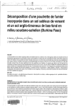
SIGI'n" AND HOLDTHIS LEVEL WITH A VERTICALTREE
:
•. :...
,
•......
:
......
I
.....
:-_ ......
_co..=,o__.u,.n,._
I
I
................ :..
, --<
(_c
:3"
_=
<'_
o. AFE.CE
Post
eo=eooeeee
I
°°°*°e*eo,
"11 (D
I
I
I1_
10 °
3o
CAUTION:
Do not operate your tractor and Chipper Vac on a
slope in excess of 10 degrees. Be sure of your tractor's towing and
braking capabilities before operating on a slope. Avoid any sudden
turns or maneuvers while on a slope.
R_
0
-I