1
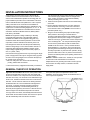
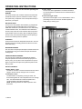
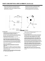
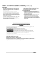
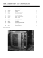
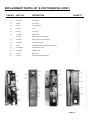
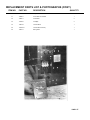
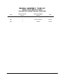
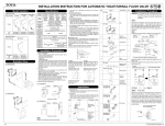
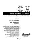
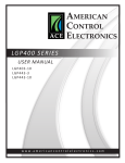
INSTALLATION, SERVICE AND
PARTS MANUAL FOR
ET4 ELECTRIC HALF SIZE
CONVECTION OVEN
VULCAN-HART COMPANY, P 0. BOX 696, LOUISVILLE, KY 40201 -0696, TEL. (502) 778-2791
IMPORTANT
OPERATING, INSTALLATION AND SERVICE PERSONNEL
Operating information for this equipment has been prepared for use by qualified and/or authorized operating
personnel
All installation and service on this equipment is to be performed by qualified, certified, licensed and/or
authorized installation or service personnel, with the exception of any marked with a ? in front of the part
number
Service may be obtained by contacting the Factory Service Department, Factory Representative or Local
Service Agency
DEFINITIONS
QUALIFIED AND/OR AUTHORIZED OPERATING PERSONNEL
Qualified or authorized operating personnel are those who have carefully read the information in this manual
and are familiar with the equipments functions or have had previous experience with the operation of the
equipment covered in this manual
QUALIFIED INSTALLATION PERSONNEL
Qualified installation personnel are individuals, a firm, corporation or company which either in person or
through a representative are engaged in, and are responsible for
1. The installation of gas piping from the outlet side of the gas meter, or the service regulator when the meter
is not provided, and the connection and installation of the gas appliance Qualified installation personnel
must be experienced in such work, be familiar with all precautions required, and have complied with all
requirements of state or local authorities having jurisdiction Reference in the United States of America National Fuel Gas code ANSI Z223 1 (Latest Edition) In Canada-Canadian Standard CAN1-B149 1 NAT
GAS (Latest Edition) or CAN1-B149 2 PROPANE (Latest Edition)
2. The installation of electrical wiring from the electric meter, main control box or service outlet to the electric
appliance Qualified installation personnel must be experienced in such work, be familiar with all
precautions required, and have complied with all requirements of state or local authorities having
jurisdiction Reference In the United States of America-National Electrical Code ANSI NFPA No 70 (Latest
Edition) In Canada-Canadian Electrical Code Part 1 CSA-C22 1 (Latest Edition)
QUALIFIED SERVICE PERSONNEL
Qualified service personnel are those who are familiar with Vulcan equipment who have been endorsed by
the Vulcan-Hart Corporation All authorized service personnel are required to be equipped with a complete set
of service parts manuals and stock a minimum amount of parts for Vulcan equipment
SHIPPING DAMAGE CLAIM PROCEDURE
For your protection, please note that equipment in this shipment was carefully inspected and packed by
skilled personnel before leaving the factory. The transportation company assumes full responsibility for safe
delivery upon acceptance of this shipment
If shipment arrives damaged:
1. VISIBLE LOSS OR DAMAGE — Be certain this is noted on freight bill or express receipt and signed by
person making delivery
2. FILE CLAIM FOR DAMAGES IMMEDIATELY — Regardless of extent of damage
3. CONCEALED LOSS OR DAMAGE — If damage is unnoticed until merchandise is unpacked, notify
transportation company or carrier immediately, and file "concealed damage" claim with them This should
be done within (15) days of date of delivery is made to you Be sure to retain container for inspection
We cannot assume responsibility for damage or loss incurred in transit We will, however, be glad to furnish
you with necessary documents to support your claim
PLEASE RETAIN THIS MANUAL FOR FUTURE REFERENCE
IMPORTANT NOTES FOR ALL VULCAN APPLIANCES
1. These units are produced with the best possible workmanship and material. Proper installation is vital if best performance and
appearance are to be achieved. Installer must follow the installation instructions carefully.
2. Information on the construction and installation of ventilating hoods may be obtained from the “Standard for the installation of
equipment for the removal of smoke and grease laden vapors from commercial cooking equipment,” NFPA No 96 (latest
edition) available from the National Fire Protection Association, Battery March Park Quincy MA 02269.
3. For an appliance equipped with a flexible electric supply cord, the cord is equipped with a three prong (grounding) plug. This
grounding plug is for your protection against shock hazard and should be plugged directly into a properly grounded three-prong
receptacle. Do not cut or remove the grounding prong from this plug If the appliance is not equipped with a grounding plug, and
electric supply is needed, ground the appliance by using the ground lug provided (refer to the wiring diagram).
(FOR GAS APPLIANCES ONLY)
4. Do not obstruct the air flow into and around the appliance This air flow is necessary for proper combustion of gases and for
ventilation of the appliance Provisions for ventilation of incoming air supply for the equipment in the room must be in accordance
with National Fuel Gas Code ANSI Z223 1 (latest edition)
5. Do not obstruct the flow of flue gases from the flue duct (when so equipped) located on the rear (or sides) of the appliance. It is
recommended that the flue gases be ventilated to the outside of the building through a ventilation system installed by qualified
personnel.
6 For an appliance equipped with casters, (1) the installation shall be made with a connector that complies with the Standard for
Connectors for Movable Gas Appliances, ANSI Z21. 69 (latest edition), and Addenda, Z21.69a (latest edition), and a quickdisconnect device that complies with the Standard for Quick-Disconnect Devices for Use With Gas Fuel, ANSI Z21. 41 (latest
edition), and Addenda, Z21. 41 a (latest edition) and Z21. 41 b (latest edition) and (2) adequate means must be provided to limit
the movement of the appliance without depending on the connector and the quick-disconnect device or its associated piping to
limit the appliance movement If disconnection of the restraint is necessary, reconnect this restraint after the appliance has been
returned to its originally installed position.
7 The appliance and its individual shutoff valve must be disconnected from the gas supply piping system during any pressure
testing of that system at test pressures in excess of 1/2 psig (3.45 k Pa)
8 The appliance must be isolated from the gas suppiy system by closing its individual manual shutoff valve during any pressure
testing of the gas supply system at test pressures equal to or less than 1/2 psig (3 45 k Pa)
CAUTIONS
FOR YOUR SAFETY
DO NOT STORE OR USE GASOLINE OR OTHER FLAMMABLE VAPORS AND LIQUIDS
IN THE VICINITY OF THIS EQUIPMENT OR ANY OTHER APPLIANCE.
1. KEEP THE APPLIANCE FREE AND CLEAR FROM ALL COMBUSTIBLE SUBSTANCES.
2. IN THE EVENT A GAS ODOR IS DETECTED, SHUT UNIT(S) DOWN AT THE MAIN
SHUTOFF VALVE AND CONTACT THE LOCAL GAS COMPANY OR GAS SUPPLIER
FOR SERVICE.
3. POST IN A PROMINENT LOCATION, INSTRUCTIONS TO BE FOLLOWED IN THE EVENT
THE SMELL OF GAS IS DETECTED. THIS INFORMATION MAY BE OBTAINED FROM A
LOCAL GAS SUPPLIER.
INSTALLATION, SERVICE & PARTS MANUAL FOR
ET-4 ELECTRIC HALF SIZE CONVECTION OVEN
All Vulcan equipment is produced with the best possible
workmanship. Proper usage and maintenance will result in
many years of satisfactory performance.
INDEX
The manufacturer suggests that this entire manual be
thoroughly read and all instructions provided within be carefully
followed.
DESCRIPTION
PAGE
DEFINITIONS OF PERSONNEL (Installation, Service & Parts)
and SHIPPING DAMAGE CLAIM PROCEDURES
(Inside Front Cover)
IMPORTANT NOTES
116021-1
INDEX
116021 - 2
CAUTIONS
116021-2
INSTALLATION INSTRUCTIONS
116021-3
GENERAL THEORY OF OPERATION
116021-3
OPERATING INSTRUCTIONS
116021-4
PREHEATING, LOADING, UNLOADING & CLEANING
116021-5
COOKING CHART
116021-5 & 6
OPERATORS TROUBLE SHOOTING
116021-7
SERVICE PERSONNEL TROUBLE SHOOTING
PARTS DESCRIPTION AND REPLACEMENT
REPLACEMENT PARTS LIST & PHOTOGRAPHS
REVISION PAGE
116021-8 & 9
116021 - 9 thru -11
116021 - 12 thru -17
(Inside Back Cover)
CAUTIONS AND NOTATIONS
NOTE:
A complete set of wiring diagrams are packaged in a separate envelope and sent out with the unit. A wiring diagram decal may also
be found on the back of the unit next to the electrical supply line.
OPENING OVEN DOOR:
Opening oven door will automatically cut "off" fan and heating elements. However, hot air gathered within the oven cavity may be
thrusted outwards when the door is opened.
CAUTION:
DO NOT stand directly in front of oven while opening door.
When opening door, operator should pull handle outward while simultaneously stepping back away from the front of the unit.
Load oven as quickly as possible to conserve heat. Center pans on racks.
NOTE:
All Vulcan electric convection ovens are equipped with an electrical rating plate indicating unit model number, serial number, unit
voltage, motor volts, motor amps, unit phase and heater kilowatts. The rating plate may be found mounted on the cover of the
terminal box located to the lower right hand corner of body back when facing unit from the front.
116021-2
INSTALLATION INSTRUCTIONS
Vulcan electric convection ovens are U.L. listed under file
number E75870 and are manufactured for use on electrical
service of the characteristics specified on the rating plate. For
proper installation procedures in the United States of America,
refer to: National Electrical code (ANSI/ N F P A No. 70 (latest
edition) Information on the construction and installation of
ventilating hoods may be obtained from the "Standard For The
Vapors From Commercial Cooking Equipment", N. F. P. A. No
96 (latest edition) available from The National Fire Protection
Association “Attention Publication Services", Battery March
Park, Quincy, MA 02269
NOTE: This equipment is design certified by a nationally
recognized testing laboratory to the appropriate national
standards as indicated on the equipment rating plate. Any
modification made without written permission of Vulcan-Hart
Corporation voids the certification and warranty of this unit.
Units designed for 208 or 240 volts will operate satisfactorily
within the voltage range of 197 to 218 and 228 to 252 volt A C
respectively Units designed for 220/380 or 240415 volt AC
require voltage supplies with ground and neutral (3-phase, 4wire, or 1-phase, 3-wire)
Units wired for three(3) phase service may be changed to single
phase or single phase units may be changed to three (3) phase
as shown on the wiring diagram and connection decal (Except
for 3-phase motor construction )
1. Remove crating with care. Remove all wood blocking,
packing, material and accessories.
2. Unit has been factory equipped and electrically connected for
use with the specific electric supply indicated on rating plate.
Check electric supply available. If the two voltages don't
agree, contact your dealer or Vulcan-Hart immediately
without proceeding to the next step.
3. Install unit in final position if this was not done while making
connection.
4. Using a carpenter's level placed on oven rack, adjust the
feet on the bottom of each leg, so that oven is level from
front to back and side to side. (NOTE: Level oven when in
permanent position only )
5. Bring the conduit containing the proper size field supply
wires (select the size and type of the field wires in
accordance with National Electric Code, suitable for carrying
the equipment's rated amps and voltage. For equipment
rated over 100 amps, 75°0 field wires must be used) to back
13
of the unit through the l -/32” hole provided in body back
and connect the phase leads (as well as neutral lead in
220/380 or 240 /415 volt A. C. units) to the field terminal
block identified by X, Y Z sections, and connect the green
grounding lead to the labeled ground lug Oven should now
be ready for operation To place the unit in operation, simply
push the master switch to the 'on" position and set the thermostat to the desired position (See operating instructions for
further details )
NOTES: In 220/380 or 240/415 A.C. models, the oven operates
on either 220 or 240 volts between the neutral wire,
independent from the grounding wire which is used to ground
the oven frame for safety reasons, is included in the main
supply leads.
GENERAL THEORY OF OPERATION
Figure 8.0 Air Flow Pattern: Shows the air flow pattern inside
the Vulcan-Hart Half Size Convection Oven The blower pulls
the air from inside the oven cavity and forces it toward the front
and back of the cavity. The forced air is then deflected through
the fan cover, towards the left side of the oven in both the front
and back. The air carries the heat from the heating elements
located behind the fan cover and distributes it throughout the
oven cavity. In general, the blower operates continuously,
while the thermostatically controlled heating elements (3
elements) are energized only when there is a demand for heat
and de-energize when the desired temperature is reached.
In the parts description and replacement section in the
installation, service and parts manual, the detailed function of
each component is explained.
A PLunger action door switch, mechanically linked with the door
shuts off both the heat and the blower when the door is opened
and will automatically reset when the door is eluded.
FIG. NO. 8.0 AIR FLOW
PATTERN
116021-3
OPERATING INSTRUCTIONS
WARNING: The oven is hot. Use care when operating and
cleaning the oven.
GENERAL
The Vulcan method of air circulation and the thermostat make
possible the Vulcan system of controlled convection cooking.
This system lets you adjust the oven for the product result you
desire from your recipes.
AIR CIRCULATION
The ET4 oven cavity shall be direct heated by (3) independent
oven elements rates at 2,000 watts each for a total input of
6,000 watts. Heated air is circulated over the oven elements by
a 9 5/32" diameter airotor. The heated air is then delivered to
the oven cavity via the fan cover and the air flow scoops to the
top and bottom of the oven cavity. After circulating throughout
the oven cavity, the air is drawn through the center opening of
the fan cover and the process is repeated.
CONTROLS
The thermostat controls the temperature that the air in the oven
will reach and cuts the heating elements off when air is at the
thermostat setting.
RECIPE ADJUSTMENT
The oven does not require special recipes. Excellent results can
be obtained from any good commercial recipe with reduced
cooking times.
TEMPERATURE ADJUSTMENT
The oven will cook or bake full or partial loads at standard
recipe temperatures when the thermostat is properly set. As
with any oven, you may wish to use a temperature of up to 25°
higher or lower than the recipe for the particular product result
that you prefer.
USE OF CONTROLS:
1. Master Switch - Item 1
The main on-off switch connects and disconnects the electric
supply to the unit controls, turning the unit "on and off".
2. Thermostat - Item 2
The thermostat is a snap-acting on-off type control. The
thermostat regulates the oven temperature from 150° through
450°. Turn dial clockwise to increase temperature and
counterclockwise to decrease temperature.
NOTE: All heating elements are under supervision of the
thermostat.
116021-4
3. Timer - Item 3
The one hour timer is graduated in one minute increments.
Turn dial clockwise to increase time and counterclockwise to
decrease time.
4. Thermostat Light - Item 4
When the thermostat light is "on" it indicates that the oven is
pre-heating or has not recovered to the dial temperature
setting during a cooking cycle.
PREHEATING, LOADING, UNLOADING & CLEANING
(STANDARD AND ROAST & HOLD OVENS)
Set the timer to the required time (see separate cooking chart).
When the preset time is up, the timer buzzer will sound, turn the
timer pointer to the "hold" position which is to the left of the "0"
minute mark.
Check the product for proper consistency and unload, or set for
additional time as required.
UNLOADING (See Caution Page)
Arrangements should be made so that adequate counter space
is available for the products to be unloaded from the oven
Rapid unloading will conserve heat, and this is essential if you
are reloading for high production. On multiple loading, close the
doors between each load and allow the oven to recover its
preset temperature. Unloading is easier if the racks are pulled
forward for better access to the pans; or if a bakers peal is
used.
CARE AND CLEANING
Stainless steel oven front may be cleaned with a damp cloth.
Stubborn soil may be removed with detergent. (Do Not Use
"Dawn".)
CAUTION: Scouring power should not be used except with
great care. Scouring powder is extremely difficult to remove
completely. It can build up accumulations that will damage the
oven. It will scratch and fog glass and can even damage and
remove corrosion resistant finishes.
Nickel plated racks and rack supports may be removed for
cleaning.
The fan cover is also removable for cleaning. Normally this is
not necessary, but will be helpful if batter or liquid is accidently
spilled into the fan area. It is recommended that fan cover be
removed at least twice yearly in order to remove debris trapped
behind the linings.
After processing some foods at low temperatures, odors may
linger in the oven. These odors may be cleared by setting the
thermostat at 450°F., then allow the oven to operate unloaded
for 30 to 45 minutes.
REQUIRED LUBRICATION
Motor bearings are packless, sealed and lubricated for life.
COOKING CHART
IMPORTANT
Recommended temperatures, times and number of racks are
intended as a guide only. Adjustments must be made to
compensate for variations in recipes, ingredients, preparation
and personal preference in product appearance.
A pan full of water may be placed in the oven bottom. This
water supplies humidity to reduce shrinkage. Water should be
added if necessary during roasting.
RECOMMENDED TEMPERATURES AND TIMES FOR
ROASTING
Meat roasting is most satisfactory at temperatures of 225° to
325°F for beef, lamb, poultry and ham; 325°F for fresh pork as
recommended by USDA and American meat Institute.
Cooking time and shrinkage may vary with roasting temperature, cut and grade of meat and degree of doneness.
Smaller cuts will generally show greater time savings than large
cuts at a given temperature.
Roasting pans should be no deeper than necessary to hold
drippings, usually 2" to 2 1/2".
RECOMMENDED TEMPERATURES & TIMES FOR ROASTING
ROASTING TEMPERATURE CHART
PRODUCT
TEMPERATURE
APPROXIMATE TIMES
Standing Rib
Roasts - oven ready
250°F
3 to 4 hours-rare
4 to 4 1/2 hours-medium
Rolled Rib Roasts
20to22lbs.
275°F
4 hours-medium
Veal Roast-15 Ibs.
300 F
4 hours - medium well
Turkeys-15 to 20 Ibs
300°F
3 hours
Meat Loaf-8to10 Ibs.
350°F
45 to 60 minutes
COOKING CHART (CONTINUED
BAKING TEMPERATURES CHART FOR STANDARD BAKING PANS 1 x 12 1/2 x 17 1/2
PRODUCT
TEMPERATURE
APPROX. TIMES
RACK POSITION*
Biscuit Products
3 Pan Bake
375°F
10 to 12 Mm
2,5 & 8
Biscuit Products
4 Pan Bake
375°F
11 to 13 Min
2,4,6 & 8
Biscuit Products
5 Pan Bake
375°F
13 to 15 Min
1,3,5,7 & 9
Cake Products
3 Pan Bake
315°F
22 to 24 Min
2,5 & 8
Cake Products
4 Pan Bake
315°F
24 to 26 Min
2,4,6 & 8
Cake Products
5 Pan Bake
315°F
26 to 28 Min
1,3,5,7 & 9
*NOTE: Rack positions are counted from bottom to top of oven cavity.
RECOMMENDED TEMPERATURES AND TIMES FOR
BAKING
IMPORTANT: When established, oven times and temperature
control settings should be noted on your recipe.
NOTES ON SPECIAL PROCEDURES FOR BAKING
In baking, the oven, its design, and proper functioning are of
great importance, but product quality and satisfactory results
are also dependent on the recipe, the ingredients used, and the
accuracy and the care with which the ingredients are measured
and the recipe instructions followed.
YEAST BREAD: Cooking starts immediately in the convection
oven. Yeast breads do not usually rise as much in a convection
oven. It is, therefore, usually necessary to allow curing and
rising times of up 2 1/2 to 3 times the increase of volume for
best cooking results.
PIES: When baking pies in your convection oven place pies on
a sheet or bun pan This procedure helps the bottom crust to
bake, makes handling easier, reduces the possibility of boil over
spoiling and enhances appearance of the pies cooked in the
lower racks.
RECOMMENDED USE OF CONTROLS
TIME REDUCTION
Because of the many variations in recipes, ingredients and
individual tastes, we do not give exact times for different
products.
The cooking charts are intended and should be used as a guide
only. When first cooking a product, check at one half recipe
time, the product may then be done or additional cooking time
may need to be estimated again
116021-6
Forced air convection cooking is faster than conventional oven
cooking and therefore over cooking is more common. Care
must be taken not to cook products faster than is practical for
the best results. Since forced convection supplies heat to the
surface of the product, the thicker or more massive a product is
for its type, the longer it will take to absorb enough heat to
cook.
POWER OUTAGE NOTE: In case of a power outage, the unit
will automatically shut down. When power is restored to the
lines, the unit will resume its normal cooking function, after the
unit thermostat light indicates that the unit has recovered to its
proper cooking temperature. However, if the unit is left
unattended during a power outage, push the master power
switch to the "off" position. When power is restored to lines,
push power switch to the "on" position, wait for the oven to preheat then resume normal cooking operations.
OPERATORS TROUBLE SHOOTING GUIDE
PROBLEM
CAUSE
REMEDY
UNEVEN BROWNING OR OVER-
TEMP. SETTING TOO HIGH, WRONG RACK
REDUCE TEMPERATURE CONTROL SETTING.
COOKING AT EDGE OF PANS.
POSITIONS USED FOR PRODUCT LOAD.
REDUCE NUMBER OF RACKS BEING USED. (SEE
SEPARATE COOKING CHART.) CHECK RACK
POSITIONS.
PULLING TO THE EDGE OF PAN OR
OVEN OUT OF LEVEL OR WARPED SHEET
HAVE OVEN LEVELED, ON THE RACKS, SIDE TO
SPILLING.
PANS.
SIDE AND FRONT TO BACK. THE RACK SHOULD
CHECK DEAD LEVEL SIDE TO SIDE AND FROM
LEVEL TO 1/8“ LOW AT THE FRONT, FROM
FRONT TO BACK. PANS USED FOR BAKING
BATTER PRODUCTS SHOULD BE KEPT
SEPARATED FROM GENERAL PURPOSE PANS. IF
ANY PAN SHOWS A TENDENCY TO WARP, IT
SHOULD BE REMOVED FROM THE BAKING
GROUP.
OVERBROWNING BEFORE DONE OR
SHRINKING AND OVER BROWNING AT
EDGES.
TEMPERATURE SETTING TOO HIGH.
REDUCE TEMPERATURE CONTROL SETTING,
INCREASE COOKING TIME. (SEE SEPARATE
COOKING CHART.)
EXCESSIVE SHRINKAGE.
FORGETTING TO MAINTAIN WATER IN OVEN
PUT A PAN OF WATER IN OVEN OR ADD WATER
OR THE USE OF TOO HIGH A ROASTING
TEMPERATURE.
TO PAN. LOWER THE ROASTING TEMPERATURE.
SERVICE PERSONNEL
TROUBLE SHOOTING GUIDE (ALL ELECTRIC CONVECTION OVENS)
This section provides a guide for trouble shooting and covers
some of the more common problems with the equipment. The
servicing personnel, as with any other equipment, need to
become familiar enough with the circuit and the components in
order to be able to follow a logical sequence of trouble shooting,
and repair malfunctions not mentioned in the following
paragraphs.
THE INSTRUMENTS NECESSARY FOR TROUBLE
SHOOTING WOULD BE:
1. A.C. voltmeter to measure line voltages up to 480 volt
2. A.C.ammeter to measure line currents up to 50 amp for 208
volt, 1-phase model.
3. Accurate thermometer to measure oven temperature up to
500"F.
PROBLEM
1. No blower, no heat.
In the following paragraphs, the voltmeter is used to measure
the voltage between 2 phases on 208 volt and between one
phase and neutral on 220/380 and 204/415 volt supplies. Do
not measure the voltage to the chassis ground. For the sake of
simplicity, when the measured voltage is referred to as 208 volt,
it is assumed that the supply is 208 volt. When supply is 240 or
220, the measured voltage rating of the oven matches exactly
(within the allowable supply tolerance) that of the field supply
Refer to the appropriate wiring diagram.
With the main power on oven circuit breakers "on' the master
switch turned to 'on' position and the oven door closed:
CORRECTION PROCEDURE
Step A—Measure the voltage between leads 42 and of the master switch.
If 208 volts, measure voltage across 21 and 48.
If 208 volts, check for a bad connection to the switch terminal.
If no voltage, check for a tripped 15-amp fuse or a bad connection to the breaker.
Check for proper connections to the door switch on leads number 13 & 14.
Turn the thermostat knob to about 350°F. If the oven indicator light is lit, follow step A.
Step A — Check for defective thermostat.
Step B — See if the heater contactor is energized (Listen for clicking sound or look at the
contactor’s plunger movement).
2. The blower is "on.
If contactor is operating, follow A, if not, follow B.
A Measure the voltage between the phases on the load side of the contactor If 208 volts look for
defective heating elements or connecting leads If no voltage, check the voltage on the supply
side of the contactor If 208 volts, the contactor is defective If no voltage, check the main
circuit breakers and supply voltage connections.
B Check the voltage on the contactor coil terminals. If 208 volts, but the contactor does not pull
in, the contactor is defective. If no voltage, check the voltage across terminals 7 and 8 of the
temperature control. If 208 volts, look for a bad connection on leads 60 and 7. If no voltage,
check for defective temperature controller.
3. The oven heats up slowly with
no food in it.
Check for tripped breakers; supply voltage, defective contactor or heating elements. Compare the
amp reading on each phase lead with the expected nominal. They should match closely.
4. The oven heats up properly
when empty, but as soon as the
food is put in it the temperature
drops and the oven never
recovers.
Meals containing excessive moisture can cause the temperature drop. Also, excess load can
cause temperature drop. The K. W. rating of the oven may not be adequate to properly handle the
type of quantity of the food in the oven.
5 The oven temperature does not
correspond with the thermostat
setting.
Place a temperature measuring device on the center rack Allow the thermostat to cycle at least 3
times If the thermostat setting and thermometer reading do not correspond with the allowable
tolerance, recalibrate the thermostat.
116021-8
SERVICE PERSONNEL TROUBLE SHOOTING GUIDE
(ALL ELECTRIC CONVECTION OVENS) Continued
PROBLEM
CORRECTION PROCEDURE
6 The oven temperature keeps
increasing beyond the setting of
the thermostat.
If the thermostat indicator light cycles on and off, check for a defective contactor (contacts
weldings). If the thermostat light remains "on", check for a defective thermostat (contacts
welding).
7 With master switch "off", the
oven heats up.
Check for defective contactor (contacts welded shut) or for shorted heating elements to ground
(the short could either be internally within the element or externally through the connecting leads
of the elements).
8 The motor turns off and
automatically comes back on after
a few minutes.
The internal thermal protector of the motor is sensing.
A High current-check for clockwise rotation of shaft, for any binding on the shaft of the blower
wheel (the wheel should rotate freely by hand touch ) If none of the above, the motor may be
defective.
B. High ambient-check for hot air leakage from inside the oven to the side through the element
seal or motor housings. Check to see if hot air is blowing on the motor from the adjacent
equipment. Check for proper ventilation in the area.
NOTE: Occasionally the over current affects the fuse circuit (15 amp breaker) before it does the
thermal protector, and the circuit fuse will keep blowing out.
PARTS DESCRIPTION & REPLACEMENT
WARNING: Disconnect the electrical power at the disconnect
switch and place a tag on the disconnect switch before
beginning any service, cleaning or maintenance procedures.
A. Switch Panel
In order to replace the components on the switch panel, it
should be taken out by removing the two screws at both top
corners.
1 Master Switch: The main on-off S. P. S. T. (single pole,
single throw) switch, providing the supply voltage to the
controls. To replace the switch, compress the spring clips
on the top and bottom of the switch while forcing it out the
front of the switch panel.
2 Oven Indicator Light: Light "on" indicates that the oven
has not reached the thermostat dial setting and is calling
for heat. Light "off" indicates that the set temperature has
been reached and that the heating elements are deenergized.
To replace, follow item 1 procedure.
3 Temperature Control: S. P. S. T. (single pole, singlethrow) relay controls the temperature of the oven from
150°F to 450°F. The normally opened contacts of the
thermostat provide power to the coil of the heating
element contactor as long as the heat is needed. Once
the set temperature is reached, the contacts open, deenergizing the contactor coil.
To replace the temperature control, disconnect all wires
from the contactor. Remove the knob and the two
mounting screws and pull the thermostat off the back of
the panel.
a For a calibration check, use a calibrated potentiometer
with the thermocouple located in the center of the center
rack. Set the dial to a mid-range temperature and allow
the oven to cycle at least three times.
b Allow the oven temperature to stabilize
c. After the stabilizing period, the instant the contactor
actuates (as noted by the thermostat "on" light turning
on), the oven temperature should be plus or minus 10°F
(6°C ) of the thermostat setting.
d. If it is within ± 10°F (6°C ) you are finished calibrating. If
not, follow steps E through H for recalibration.
e Loosen the set screw in the temperature control knob
Rotate knob without moving shaft and set the knob to
match the potentiometer reading.
f. Retighten the set screw. CAUTION: Do not over-tighten
g Turn the dial to the desired temperature.
h. Repeat steps A through C.
116021-9
PARTS DESCRIPTION & REPLACEMENT (Continued)
A. Switch Panel (Continued)
4. Timer (one-hour model) The normally open and common
contacts of the electric timer are connected together
energizing the timer motor when the knob is set to the
desired position. Once the timer completes its set interval
(returns to the zero mark) the
common terminal disconnects from the timer motor
(shuts the motor off) and connects with the buzzer
The buzzer will continue to sound until the knob is
manually turned to "hold' position where all
contacts are opened (timer motor and buzzer
turned off) (Figure No 16 rear view component)
FIG. NO. 16.0 REAR VIEW SCHEMATIC
COMPONENT
phase motors, interchange any two supply leads to convert
B. Blower Motor
counterclockwise to clockwise rotation.
The blower motor has internal thermal protection, and its
sealed bearings do not require any lubrication. The
mounting of the blower assembly is as follows.
C. Oven Heating Elements
The three heating elements are mounted on the right cavity
Remove fan cover by loosening (2) 10-24 screws in front of
side behind the fan cover and can be serviced as follows:
fan cover. Loosen and remove (1)10-24 screw and nut from
Remove the two screws holding the fan cover. Slide fan
thermistor probe, letting probe rest on cavity bottom.
cover forward then slightly outward into the oven cavity.
Remove fan cover from oven cavity.
Loosen & remove (1) 10-24 screw, nut and washer from
Loosen setscrew on the airotor with an allen wrench. Pull
thermistor probe, letting probe rest on cavity bottom. Pull
airotor forward off the motor shaft with a wheel puller.
the fan cover forward and out of the oven cavity. Remove
Remove switch panel as described in section A" on page
switch panel by removing (2) screws at both top corners
116021 –19. Remove the panel in the outer right body side
Remove the panel in the outer right body side by accessing
by accessing (2) 10-24 screws through control compartment
(2) 10-24 screws through the control compartment in top and
in top and bottom flanges of the outer right body side panel.
bottom flanges of the outer right body side panel. From
Remove the four nuts holding the motor mounting plate from
inside control compartment, remove (2) #10-32 nuts and
inside control compartment.
washers from appropriate element to be removed. Next,
from inside the oven cavity, remove (2) 10-24 screws holding
Pull the motor assembly forward and out of the control
the element brackets of the appropriate element to be
compartment. Remove the junction box cover and the
removed. From inside the oven cavity, remove the element
supply leads.
from the right cavity side. Replace element.
NOTE: The motor is suitable for connection of two different
NOTE: Make sure foil gasket is positioned between the
voltage supplies. Check the connection instruction inside the
element bracket and the right cavity side when reinstalling
motor junction box cover to assure proper connection for the
element.
available voltage supply.
The direction of rotation is clockwise as viewed from in front
of the fan cover. The 1-phase motors are internally designed
for C W (clockwise) rotation On 3-
116021-10
PARTS DESCRIPTION & REPLACEMENT (Continued)
D. Door Switch
With the oven door closed, the normally open contact of the
door switch is closed providing power to the element and
motor controls. When the door opens, the normally open
contact is de-energized and the element contactor and the
blower are turned off.
Remove switch panel as described in section "A".
To adjust or replace the door switch, remove the two #8
mounting screws on left side of control compartment and
remove micro switch cover. This will expose (2) 2 3/8" dia.
holes in right inner body side. The micro switch is accessed
through bottom 2%" dia. hole.
To replace door switch, remove nut on micro switch shank
which protrudes through the front frame. This will allow
removal of defective micro switch and replacement of new
one through lower 2%" dia. access hole.
NOTE: In order for proper door switch actuation, the relative
location of spacer washers behind front frame should be
noted on defective door switch and their position closely
approximated upon new door switch installation.
E. Power Panel Assembly
1. Contactor. The 4-pole (208, 240 volt models) and 3-pole
(220/380 & 240/415 volt models) contactors when
energized by the thermostat and the load control, provide
power to the heating elements.
2. Buzzer. Signaled by the timer, the buzzer sounds when
the pre-set time is completed.
To replace, cut both wires approximately 3" from the
buzzer and strip the ends. Remove the bracket holding
the defective buzzer. Install the new buzzer equipment
with its mounting bracket and lead, and connect the wires
with wire nuts.
REPLACEMENT PARTS LIST AND PHOTOGRAPHS FOR
ELECTRIC CONVECTION OVENS WARNING ALL SERVICE
PERSONNEL
When servicing this equipment, use only certified controls duplicating those originally supplied on this
equipment by Vulcan-Hart Corporation.
DO NOT SUBSTITUTE Components with different model numbers.
DO NOT SUBSTITUTE Components with different manufacturing names.
DO NOT SUBSTITUTE Components with rebuilt controls without authorization from Vulcan-Hart
Corporation. Any unauthorized substitution of controls as stated above may be safety hazard and will
automatically void the warranty and the certification associated with this equipment.
REPLACEMENT PARTS ORDERS
The following information must accompany a replacement parts order or it cannot be filled.
A. Model and serial number.
B. Type of gas.
C. Unit voltage, amperage and motor phase.
D. Appliance finish — black, gray, stainless steel, etc.
This information may be found on the unit rating plate. Parts may be ordered from your dealer, service
agency, or parts distributor. For further information concerning parts ordering location, contact Vulcan-Hart
Corporation, 3600 North Point Blvd., Baltimore, Maryland 21222.
116021-11
REPLACEMENT PARTS LIST & PHOTOGRAPHS
ITEM NO.
PART NO.
DESCRIPTION
1
115952-G1
Oven Door Handle Assembly (Including Strike Plate)
1
2
115710-G1
Oven Door Assembly
1
3
115689-1
Top Channel Finishing Piece
1
4
115695-G2
Body Top Assembly
1
5
111294-2
Door Window
1
6
115690-1
Bottom Channel Finishing Piece
1
7
115758-D
Decal Control Panel Standard
1
8
115747-G1
Control Panel Assembly (NS)
1
9
115704-G2
Body Side, Outer Right Assembly
1
10
115694-2
Body Side, Left (NS)
1
11
115692-G2
Panel, Outer Right Body Side
1
12
103981-2
Hinge Pin (NS)
2
13
104629-2
Hinge Pin Bearing
2
7A
115758-D1
Decal Control Panel, Roto-Digital (NS)
1
14
115778-1
Adjustable Legs (NS)
4
56
116027-1
Silicone Gasket, Door Latch
1
NS = Not Shown By Photo
QUANTITY
REPLACEMENT PARTS LIST & PHOTOGRAPHS (CONT.)
ITEM NO.
PART NO.
DESCRIPTION
QUANTITY
15
115728-1
Oven Cavity Top
1
16
115729-G1
Oven Cavity Bottom
1
17
115730-G1
Oven Cavity, Right Side
1
18
115732-G1
Oven Cavity, Left Side
1
19
102558-4
Capillary Clip Standard *Different No. For Roto-Digit Probe)
1
20
115682-1
Oven Rack Support, Right Side
2
21
115682-2
Oven Rack Support, Left Side
2
22
113951-1
Clip Rack Support
8
23
115683-1
Oven Rack
5
24
115745-G1
Door Seal Assembly Sides
2
25
115746-G1
Door Seal Assembly, Top & Bottom
2
26
111496-F5
Micro Switch
1
27
115701-G1
Fan Cover Assembly
1
28
115809-1
Cover Piece, Fan
1
29
115780-9
Airoto CC ½” Bore 9 1/8” O.D.
1
30
S06089
Scrulug
1
31
113994-2
Motor
1
32
115823-1
Spacers, Fan Cover Piece
33
115727-G1
Oven Cavity Back
1
34
115814-1
Element, Inner 208V
1
34A
115814-2
Element Center, 208V
1
34B
115814-3
Element, Outer 208V Select As Required
1
34C
115814-4
Element, Inner 240V
1
34D
115814-5
Element, Center 240V
1
34 E
115814-6
Element, Outer 240V
1
35
113840-1
Temperature Switch
1
55
114141-5
Thermistor Probe (Standard)
1
55A
116471-2
Thermistor Probe (Rota-Digital) (NS)
1
57
116462-G1
Motor Mounting Plate Assembly
1
58
115844-2
Air Scoop
2
59
115762-1
Door Liner
1
60
115227-2
Gasket, Door Liner
1
61
116286-1
Insulation, Motor Mounting Plate
1
12
REPLACEMENT PARTS LIST & PHOTOGRAPHS (CONT.)
116021-14
REPLACEMENT PARTS LIST & PHOTOGRAPHS (CONT.)
ITEM NO. PART NO.
DESCRIPTION
QUANTITY
8
115747-G1
Control Panel Assembly
1
36
111496-B4
Power Switch
1
37
116280-1
Thermostats
1
38
114524-1
Thermostat Knob
1
39
111690-2
Timer
1
40
111242-1
Timer Knob
1
41
111496-E4
Heating Light
1
7
115758-D
Decal, Control Panel (Standard)
1
7A
115758-D1
Decal, Control Panel (Roto-Digital)
1
42
111496-B3
Rocker Switch (Red)
2
43
116471-1
Roto-Digit Computer Board With Setting Display
1
44
414254-00001
Computer Setting Knob
1
45
111496-E12
On/Ready Light
1
46
111499-1
Buzzer, 230V
1
66
111500-11
Transformer Roto-Digit 220V/10V
1
116021-15
REPLACEMENT PARTS LIST & PHOTOGRAPHS (CONT.)
ITEM NO.
PART NO.
DESCRIPTION
31
113994-2
Motor
1
47
116461-1
Motor Mount Insulation
1
48
417934-G1
Porcelain Block
1
49
111497-D3
Contactor
1
63
115705-G1
Inner Right Body Side Assembly
1
64
115696-G1
Body Bottom Assembly
1
116021-16
QUANTITY
REPLACEMENT PARTS LIST & PHOTOGRAPHS (CONT.)
ITEM NO.
PART NO.
DESCRIPTION
QUANTITY
50
115757-G1
Body Back
1
51
115688-1
Cover Plate Terminal Box
1
52
113807-1
Fuse Holder
2
53
113799-2
Fuse(NS)
2
54
110472-8
Terminal Block
1
62
115738-G1
Terminal Box Assembly
1
65
113810-1
Rating Plate
1
116021-17
MANUAL ASSEMBLY: 116021-G1
INSTALLATION, SERVICE & PARTS
ET4 ELECTRIC CONVECTION HALF SIZE OVEN
SIGN
MANUAL 116021-G1
SUB NO.
SHEET PART NUMBER
AFFECTED
DATE
DML
0
116021-1 through-23
06-04-87
DML
1
116021-1 through-18
04-01-89
DML
2
116021-16
12-10-90
116021-18