1
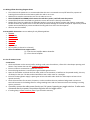
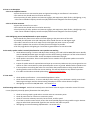
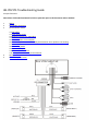
JBL PRV175 Troubleshooting Guide Prospec Electronics Note: Please click underlined words for links to particular parts in this document and our website. 1 2 3 Wiring Compatible Accessories List of common issues 4 5 3.1. No power 3.2. Intermittent Power 3.3. Buttons/controls not responding 3.4. USB issues 3.5. Poor reception or no reception 3.6. No audio, speaker audio is unevenly distributed or some speakers not working 3.7. Low audio 3.8. Fluctuating Audio 3.9 Moisture in Display 3.10 Bluetooth Won’t Work 3.11 Extra yellow wire on 12 pin wire harness Reset procedure External amplifier issues 1.0. Wiring Follow the wiring diagram above • • • • • • The red wire is the power wire. It recommended that this wire is connected to an on/off switch for purposes of lowering the current draw on the battery while the radio is not in use. Red ACC wire must be connected to 12V+ for the radio to turn on. Note: the PRV175 has EPROM, which means the radio loses power, it will still retain the presets. Ground (black) must be connected to a good 12V- source. Best source is directly to the battery. Speaker wires must be installed to the individual speaker’s terminals as labeled, positive and negative, respectively. Do NOT combine any speaker wires as this will cause permanent damage to the radio’s output IC. Tape off any unused speaker wires individually to prevent accidental shorting which can also harm the output IC. Antenna must be installed. 2.0 Compatible Accessories- see our website for the following add ons. • SEAMINI • SEAUSBMINI • MIL-RF9-UART • MIL-REM50 • JBLMC20 • REX20-6 • Any antenna • Any amplifier (2 channel or 4 channel) • Note: the JBLPRV175 can support either: (1) 1 two channel amplifier AND a subwoofer (2) 1 four channel amplifier 3.0. List of common issues 3.1 No Power Check each button on the control pad for sticking. Under normal conditions, a faint click is heard upon pressing each button. If any button does not click, initiate a warranty claim. Ensure red wire is connected to a good 12V+ source. Ensure black ground wire is connected to a good reliable ground source. Open the fuse holder and check the fuse. Note, while in most situations, a bad fuse can be spotted visually, this may not always be the case. The best method would be to use a multi-meter or a test light. Ensure the battery/power supply is putting out at least 12V while under load. The radio requires at least 11V to operate normally. Check all connections for corrosion, looseness, or other condition that can produce a bad ground. Corrosion or terminal looseness is the leading cause for most grounding issues and can cause excessive heat resulting in melting wires or terminals. If possible, connect the radio power directly to a 12V system, bypassing any toggle switches. If radio works connected directly to power, the problem might be with the toggle switch. If nothing helps, initiate a warranty claim if you are within warranty 3.2 Intermittent Power 3.2.1 Powers on and off constantly Check voltage under load. At least 11V must be maintained consistently to operate the radio normally. If voltage cannot be maintained, load test the battery or power supply. Check all connections for corrosion, looseness, or other condition that can produce a bad ground. 3.2.2 • Check wire harness by wiggling the wire harness on the radio and the vehicle side. If the whole pin comes out, bend the holders on the pin so that the pin will stay in the plug (see below image). If the wire comes out of the pin, initiate a warranty claim so we can re-pin the radio. Powers off and on while vehicle is moving Inspect all connections including the radio’s harness for looseness. Wiggle connections while the radio is operating to produce the symptom and narrow down the loose connection. If radio cuts in and out while wiggling the wires on the radio side of the wire harness, initiate warranty claim. 3.3 Buttons/controls not responding Press each button to ensure a click is heard signifying the button is mechanically operational. If one or more buttons do not click, initiate a warranty claim. Detach any additional equipment connected to the radio such as remotes, remote adaptors, and extensions. If the stereo returns to normal operation, plug one attachment in at a time until the discovering the defective part. Check all remote connections for water intrusion or corrosion including the MC20/REM50 themselves. This includes any extensions connected to the radio or remote. If any connections are corroded, replace the corresponding part. The best corrective measure to prevent this from happing again is to seal this connection with an adhesive shrink tube and heat gun. If these materials are not readily available, make sure all connections are higher than the mounting location of the remote and radio so any water entering these areas does not follow along the cable and into the connection. Also make sure these connections are in dry areas. Reset the microprocessor-see 4 for reset procedure. 3.4 USB issues 3.4.1 iPod/iPhone not charging or playing – these devises are not supported. To play iPod/iPhone, use the headphone jack and connect to the AUX inputs of the JBLPRV-175. Recommended additional purchases are the SEAMINI or SEAUSBMINI. 3.4.2 MP3 player is not charging or playing – not all mp3 players will play via USB. The difference is in the software of the mp3 player. Recommended additional purchases are the SEAMIN2 or SEAUSBMINI. 3.4.3 Flash Drive/ Thumb drive not playing Only MP3 or Windows Media files are supported. These files can be recognized by viewing their file extension on a computer; i.e., the file “My Favorite Song” will be followed by a “.” and the extension “mp3” or “wma”. Some computer operating systems have extension view disabled. The feature can usually be enabled in the computer’s folder properties. ITunes music files will not play as these are not in mp3 format. Software converters can be purchased to convert these files as others to mp3 format. Do not exceed a bit rate of 128 Kbps when converting. Only drives formatted to FAT are supported. Most flash drives come this way standard. Some flash drives com preloaded with proprietary software or other media organizational software that will prevent the PRV175 from reading the contents. Best practice is to completely format the drive to erase all contents before loading music files. Supported formats must not exceed a bit rate of 128 Kbps. Check USB outlet for corrosion or rust. 3.5 Poor or no Reception 3.5.1 For an amplified antenna Ensure the antenna is connected to power and ground according to manufacturer’s instructions. The antenna wire should never be coiled or wound up. Check proximity of radio, speakers and antenna to gages, GPS equipment, depth finders, LED lighting, or any other source of Radio Frequency Interference (RFI) and Electronic Magnetic Interference (EMI). 3.5.2 For all other antennas Inspect the antenna for torn wires The antenna wire should never be coiled or wound up Check proximity of radio, speakers and antenna to gages, GPS equipment, depth finders, LED lighting or any other source of Radio Frequency Interference (RFI) and Electronic Magnetic Interference (EMI). 3.5.3 LED lighting causes low FM/AM audio or poor reception Never bundle the power source wires of the LED lighting to the power wires of the radio. If needed, the LED power wires and radio power wires should intersect at a 90 degree angle. The radio’s antenna must be as far away from the LED lights and power source as possible. The radio’s speakers also must be as far away from the LED lights as possible. If all fails, upgrade the LED lighting to a brand that is guaranteed not to emit RF or EMI. 3.6 No audio, speaker audio is unevenly distributed or some speakers not working Check Balance settings. To access and adjust these settings, press and hold the MODE/SEL button. Quickly press the MODE/SEL button again and again until the desired setting is displayed. Use the volume buttons to adjust to zero for FAD and BAL. Center the adjustment between left/right. Check speaker connections. Ensure each speaker wire is routed to the appropriate speaker terminal for which it is intended. Inspect all speaker wires for exposed wire and tape up as necessary. Make sure they cannot ground to one another or make contact with any other potential power source or ground. NEVER combine speaker wires. If some speakers are working but others are not and the above methods do not help, swap the known working speakers with the ones that are not working. This will help determine any defective speakers. If no audio and the above methods yield nothing, initiate a warranty claim. 3.7 Low Audio Check speaker specifications – recommended impedance is 4ohm Check sound enhancements - To access and adjust these settings, press SEL button. Quickly press the SEL button again and again until the desired setting is displayed. Use the volume buttons to adjust. LED lighting can cause low FM/AM audio – see section 3.5.3 3.8 Fluctuating audio or FM signal - Audio level constantly raises and lowers when the engine is started or revved. This issue is more frequently caused by power fluctuations than radio failure. Check to ensure ground is good and no corrosion exists at connection points. Check all power wire for corrosion at connection points. Check for corrosion at battery terminals, bus terminals, and fuse panel. If in a boat or another motor vehicle, ensure the recommended plugs are being used the engine. Resistor plugs can often block unwanted RF signal that can interfere with radio reception. LED lighting can cause fluctuating FM/AM audio – see section 3.5.3 3.9 Moisture in Display 3.9.1 Water seen inside display after washing the mounting area Radio is not designed to withstand pressurized streams of water. When rinsing the radio or around the radio, a very low pressure spray is recommended. Monitor the display for possible evaporation without harm to the radio. Monitor the radio for strange or erratic behavior. If the issue persists, internal damage has occurred – seek to repair or replace. 3.9.2 Slight fog after operation – normal in colder weather. Allow radio to run for 1-2 hours; this will burn off moisture. 3.9.3 Heavy condensation The condensation may evaporate without harm to the radio. See “slight fog after operation.” Monitor the radio for strange or erratic behavior. If the issue persists, internal damage has occurred – seek to repair or replace. 3.10 Bluetooth Won’t Work ATTENTION: PLEASE SEE OUR PAIRING GUIDE ON THE PRV-175 FOR THE MOST POPULAR BLUETOOTH DEVICES HERE 3.10.1 Bluetooth Won’t Pair Make sure your Bluetooth device is turned on and set to PAIR first Make sure the JBLPRV-175 is on BT MUSIC. Hold down the MODE/SEL button until BT PAIR appears. Then, select the PRV-175 on your Bluetooth device. Note: It might require multiple pairing attempts before the radio pairs. Turn all other Bluetooth devices off so the radio doesn’t get confused with what Bluetooth device to pair to. Turn the pairing on the Bluetooth device first before pairing is turned on the radio. Reboot your Bluetooth device. Turn off the Wi-Fi on your Bluetooth device. Reset your radio using the reset procedure in 4. Try with another Bluetooth device. If your Bluetooth device will not reconnect, check your PO on the radio for AL01543814. If you have this PO, please contact us for a software update. Initiate warranty claim if nothing above works. Note: Bluetooth will only work with Bluetooth streaming in but not out. This means that phones can stream Bluetooth music in, but Bluetooth headphones that stream out will not work. 3.11 Extra yellow wire on 12 pin wire harness Since the PRV175 has an auto memory, the radio doesn’t need a yellow memory wire and therefore, does not have a connection for it. 4 Reset Procedure Power the radio off. Then press TUNE BACK, and then TUNE FORWARD in rapid succession 3 times each. The radio will then show SYS CLR. Note: this will clear the presets. Disconnect the 12 pin connector plug from the power and ground for 30 seconds. 5 External Amplifier Issues 5.1 Strong hiss –reduce the input gain on the amplifier until the hiss is reduced to an acceptable level while still maintaining performance. Note, if both amplifier and stereo output can produce distortion, the input gain is much higher than it needs to be. In most situations, reduced gain levels will not produce detectable performance conditions. Put an RCA filter in between the radio “Line Out” connection and the amp. 2 of these can be put on the connection to remove the feedback. 5.2 Amplifier volume fluctuates or amplifier turns off and on • Check the grounds to both amplifier as well as radio. Corrosion on any the contacts will reduce the ground. • Check system voltage while operating radio and amplifier. If the voltage fluctuates and drops below 11.5 volts, load test the battery, check the charging system, and check all power and ground wires and contacts for looseness or corrosion. • Ground the amplifier’s chassis to the stereo’s chassis. 5.3 Audio is extremely low - check the amplifier’s gain setting and increase if necessary.