1
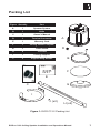
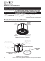
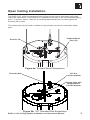
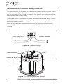
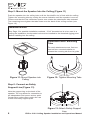
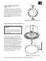
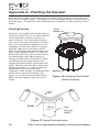
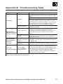
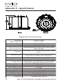
EVID C12.2 User Manual
Table of Contents
Table of Contents ............................................................................................................. TOC
Safety First ....................................................................................................................... TOC
Packing List ............................................................................................................................ 1
EVIDTM C12.2 Models ............................................................................................................. 2
Product Feature Identification ............................................................................................... 2
Pendant Mount Installation ..................................................................................................... 3
Ceiling Tile Installation ............................................................................................................ 4
Step 1 - Cut the Hole ..................................................................................................... 4
Step 2 - Install C-Ring and Tile Rails .............................................................................. 4
Step 3 - Attach Wiring to the Terminal Connector ......................................................... 5
Step 4 - Secure the Cable to the Speaker .................................................................... 7
Step 5 - Mount the Speaker into the Ceiling .................................................................. 8
Step 6 - Connect an Auxilary Support Line .................................................................. 8
Step 7 - Adjust Tap Selector .......................................................................................... 9
Step 8 - Insert the Grille ................................................................................................. 9
Appendix A - Painting the Speaker ...................................................................................... 10
Appendix B - Troubleshooting ............................................................................................. 11
Appendix C - Specifications ................................................................................................ 12
Notes ................................................................................................................................... 13
Safety First
Suspending any object is potentially dangerous and should only be attempted by individuals who have a thorough knowledge of the techniques and regulations of rigging objects
overhead. Electro-Voice® strongly recommends that all speakers be suspended taking into
account all current national, federal, state and local regulations. It is the responsibility of
the installer to ensure that all speakers are safely installed in accordance with all such
regulations. When speakers are suspended, Electro-Voice® strongly recommends that the
system be inspected at least once a year. If any sign of weakness or damage is detected,
remedial action should be taken immediately. The user is responsible for making sure that
the supporting surfaces, and any additional hardware used, is capable of supporting the
loudspeaker. Any hardware used to suspend a loudspeaker array that is not provided by/
associated with Electro-Voice® is the responsibility of others.
TOC
EVIDTM C12.2 Ceiling Speaker Installation and Operations Manual
Packing List
Figure Quantity
Part
A
1
Speaker System
B
1
Grille
C
1
Owner's Manual
D
1
Terminal Connector
E
1
Warranty Card
F
1
Ceiling Cutout Template
G
1
Paint Shield
H
2
Tile Rails
I
1
C-Ring Support
J
2
Support Ring Screws
A
D
B
F
E
C
G
I
J (x2)
H (x2)
Figure 1: EVID C12.2 Packing List
EVIDTM C12.2 Ceiling Speaker Installation and Operations Manual
1
EVIDTM C12.2 Models
Model
Part No.
Description
12" Coaxial Speaker System, Consists of CE-12 and
EVID 920-8B Assembled, 64W Transformer with ASC*
12" Enclosure for EVID 920-8B, Includes 64W
CE-12 301921-100
Transformer with ASC*
High-Efficiency 12" Coaxial Driver, 100 dB
EVID
901922-100
920-8B
Sensitivity, 200W Power Handling
C12.2
301920-000
*Automatic Saturation Compensation
Product Feature Identification
Steel
Backcan
Tap
Selector
Pendant
Mount
Tabs (x3)
Mounting Tab
Screws (x4)
Figure 2: Bottom of Speaker
Removable Input
Terminal Connector
3/8” Threaded
Rigging Point
Seismic Tab
Strain Relief Fitting
Terminal Cover
Plate
Grille Safety
Tether
Rotating Mounting
Tabs (x4)
Grille
Figure 3: Top of Speaker
2
EVIDTM C12.2 Ceiling Speaker Installation and Operations Manual
Open Ceiling Installation
The EVID C12.2 must be suspended from the back of the can in both open ceiling and
ceiling tile applications, using either the 3 pendant mount tabs or the 3/8” threaded rigging
point. To prevent rattles, rotate the 4 mounting tabs towards the can, then tighten the
mounting tab screws.
The seismic tab may be used in addition to the pendant mounts as a redundant safety
point.
Pendant Mount
Tabs (x3)
Seismic Tab
Figure 4a: Pendant Mount Suspension
3/8” Nut
(Loctite Applied)
Threaded Rod
Rigging Plate with
Integrated Nut
(Loctite Applied)
Figure 4b: 3/8” Threaded Rod Suspension
EVIDTM C12.2 Ceiling Speaker Installation and Operations Manual
3
Ceiling Tile Installation
Step 1: Cut the Hole (Figure 5)
Cut out the hole by tracing the cardboard template or with a circular cutter set to the
appropriate cutout size. If the wire has been pre-installed, pull the wiring through the cutout
hole.
Figure 5: Cut Ceiling Hole
Step 2: Install C-Ring and Tile Rails (Figure 6)
For suspended ceiling installations, insert the C-ring through the hole cut in the ceiling tile.
Place the C-ring around the hole with the tabs located as shown in Figure 6. Insert the tile
rails through the cut hole in the ceiling tile. Snap the two rails into the two tabs in the C-ring
and align the rails so that the ends extend OVER the T-channel grid on the side of the tile.
Secure the rails onto the C-ring tabs by inserting a screw though each tab into the rail, as
shown in Figure 6.
Figure 6: Secure Rails to C-Ring
4
EVIDTM C12.2 Ceiling Speaker Installation and Operations Manual
Installation Note: Tile Rails and C-Ring
The tile rail accessory is designed to fit either standard 24-inch-wide or
600-mm-wide tiles. It is important to note that the tile rail pieces do not
actually attach to the T-grid struts.The ends of the rails sit OVER the Tgrid strut. Normally, the tile supports the rails. The tile rails are prepunched at regular intervals with holes along their length.This allows the C-ring to be
positioned at any point along the rail. If the tile comes out or falls apart, the ends of
the support rails fall onto the T-grid, which prevents the speaker assembly from
falling. Always use all included support hardware when installing into suspended
ceiling tiles to make sure the installation is secure. For sheetrock ceiling installations,
the tile rail is not needed, but the C-ring should be used to reinforce the ceiling
material and to spread out the pressure from the speaker hold-down tabs. Guide the
C-ring through the cut hole in the ceiling, and place it on the back side of the hole
before inserting the speaker.
Installation Note: Ceiling Tile Caution
When mounting the C12.2 into 2'x2' or 2'x4' suspended ceiling tiles or
sheetrock ceilings, DO NOT install the C12.2 without using either the 3/
8” threaded rod rigging point or the pendant mounts. Ceiling tiles are not
designed to support any substantial weight and will cause the tile to sag
and distort, even with the tile bridge installed. If the cables are used, they MUST be
strung taut. The threaded rod or cables MUST support most of the weight of the
speaker to ensure that the C12.2 does not deform the ceiling.
Step 3: Attach Wiring to the Terminal Connector (Figure 7)
Insert the bare end of wire into the appropriate connector terminals as described below
and screw down the hold-down screw until tight, using a small screwdriver.
er
riv
wd
cre
S
Figure 7: Tighten with Screwdriver
EVIDTM C12.2 Ceiling Speaker Installation and Operations Manual
5
Installation Note: Connector Wiring Guidelines
The input connector’s 4 terminals are numbered and marked on the connector. Pins 1
and 2 are positive (+); pins 3 and 4 are negative (–). (Pin 1 is connected to Pin 2 and
Pin 3 is connected to Pin 4 inside the speaker.) Pins 1 and 4 are used as daisy-chain
connections to other loudspeakers.
For wiring in parallel, connect the wire pair of the subsequent speaker to pins 1 and 4.
When one input connector is removed, subsequent speakers will also be
disconnected. See Figure 8.
When all wiring has been completed to the connector, plug the connector into the
socket in the speaker’s terminal cup. See Figure 9. Tighten all screws to eliminate
vibration.
From amplifier or
previous speaker
To next speaker
Figure 8: Parallel Wiring
Horizontal Screw
Input Connector
Hold-Down Screw
Strain Relief Screws
Terminal Block
Figure 9: Plug Connector into Socket
6
EVIDTM C12.2 Ceiling Speaker Installation and Operations Manual
Step 4: Secure the Cable to the Speaker (Figure 10)
Fully loosen the horizontal screw shown in Figure 9, then the strain relief screws. Run the
wires through the opening in the fitting and plug the input connector into the speaker’s
terminal block. Then tighten the strain relief fitting as follows:
If plenum cable is used, slide the cable through the strain relief fitting on the terminal cover
plate (Figure 10). Hold the strain relief fittings tight around the cable. Tighten the strain
relief screws first, then the horizontal screw. In the cases of insulated speaker wire and
plenum cable, it is often possible to provide acceptable strain relief force by simply
tightening the strain relief screws onto the terminal cover plate.
Figure 10: Secure Cable through Fitting
EVIDTM C12.2 Ceiling Speaker Installation and Operations Manual
7
Step 5: Mount the Speaker Into the Ceiling (Figure 11)
Push the speaker into the ceiling hole until the front baffle rim is flush with the ceiling.
Tighten the mounting tabs by turning the screw clockwise until the speaker is secure.
Please note that the first clockwise quarter turn rotates the attachment tabs outward.
The remaining turns tighten the tabs down onto the back of the ceiling surface (see
Figure 12).
Installation Note:
See Page 3 for possible installation methods. If 3/8” threaded rod is to be used in a
ceiling tile installation, the threaded rod must be installed to the threaded rigging point
before installing into the ceiling.
Installation Note: Mounting
Tabs
For each attachment screw, first turn
one half turn counterclockwise to
release the counting tab from its guide.
Figure 11: Mount Speaker into
Ceiling
Figure 12: Tighten Mounting Tabs
Step 6: Connect an Safety
Support Line (Figure 13)
Note the support ring on the back of the
speaker. The ring allows for connection to
an independent and secure anchor point.
Construction codes often require the use
of this secondary support point.
Figure 13: Attach Safety Support
Line
8
EVIDTM C12.2 Ceiling Speaker Installation and Operations Manual
Step 7: Adjust Tap Selector
(Figure 14)
The tap selector switch is located on the
front baffle. Adjust the speaker to the
appropriate tap setting before installing the
grille. In some 70V/100V constant voltage
installations it is advisable to leave the
grilles off if final speaker audio level
balance adjustments are to be made later.
After the levels are adjusted the grilles can
then be installed.
Figure 14: Adjust Tap Selector
Step 8: Attach the Grille (Figure 15)
Installation Note: Grille Safety
Feature
EVID grilles features a unique safety
tether to prevent the grille from falling if
the grille is removed or comes loose
after installation.
First, install the grille’s safety tether by
pushing the grille fastener into the hole in
the front of the baffle (see Figure 15).
Second, press the grille into place until the
front of the grille is flush with the rim of the
baffle. Make sure the grille is securely
seated to prevent it from vibrating loose. If
you need to remove the grille, the easiest
way is to insert two bent paper clips or
other pointed objects into holes in the
grille, then apply slow even pressure to
pull down on the grille until that section of
the grille comes out slightly. Continue the
same procedure around the perimeter of
the grille, loosening a portion at a time
until the grille is removed.
Figure 15: Attach the Grille
EVIDTM C12.2 Ceiling Speaker Installation and Operations Manual
9
Appendix A - Painting the Speaker
If the speaker is installed in an area where the interior design requires a color match, the
EVID C12.2 is simple to paint. The speaker can accommodate almost any type of latex or
oil based paint. The bezel/rim can be painted before installation or after mounting into the
ceiling.
Paint
Shield
Painting Process
Clean the rim and grille with mineral spirits or
other light solvent. Do not use harsh solvents
such as gasoline, kerosene, acetone, or
other chemicals. If you use these cleaners
you may permanently damage the enclosure.
Also, don’t use abrasives products such as
sandpaper or steel wool. Either by rolling or
spraying, apply two or more thin coats of
paint. If you are spraying, hold the spray can
at the angles shown in Figure 17. If you are
painting the grille also, you must first remove
the internal grille cloth. Spray painting is
strongly recommended. If the grille is rolled
or brush painted, the grille may become
clogged with paint and the sound quality will
suffer. After the paint has dried, replace the
internal grille cloth. If you wish to paint the
speaker along with the ceiling after
installation, insert a plastic or cardboard paint
shield into the front of the speaker (see
Figure 16) to mask the drivers and internal
baffle, paint the speaker, then remove the
shield.
Speaker
Figure 16: Installing Paint Shield
Before Painting
180˚
45˚
Baffle
45˚
180˚
Can
(do not
paint)
Figure 17: Spray-Painting Angles
10
EVIDTM C12.2 Ceiling Speaker Installation and Operations Manual
Appendix B - Troubleshooting Table
Problem
Possible Causes
Action
Make sure the amplifier channel is being fed an input
signal (preferably via a "signal input" indicator on the
amp).
Check that the amplifier channel's volume is turned up.
Amplifier
Connect the speaker and cable, which had no output
No Output
to another amplifier channel, making sure an imput
signal is fed to the new ampl channel. If you then get
output, the problem was the amplifier channel. If not,
then the problem may be in the cable or speaker.
Replace the cable(s) connecting the loudspeaker
Speaker Cable(s)
system and amplifier.
Check all cabling for proper connector contact. A bad
connection can result in intermittent contact or
dramatically increased resistance, which in turn can
Faulty Connection
Questionable or
cause reduced output or noises unrelated to the
Intermittent Output
signal.
such as Crackling
Check the power tap setting under the speaker grille to
Improper Power Tap
ensure the setting is appropriate for the installation
Setting
and amplifier chosen.
A Faulty Electronic
Since loudspeakers cannot generate these sounds by
Constant Noise
Device in the Signal themselves, you may have a faulty electronic device in
such as Buzzing,
Chain
the signal chain.
Hissing or
P
o
o
r
S
y
s
t
e
m
Humming
Check and correct the system grounding, as required.
Grounding
When two speakers are hooked up out of polarity (out
of phase), the low frequencies cancel each other out.
Out-of-Polarity
Try reversing the polarity of one of the speakers either
Poor Lowby turning around a dual-banana plug at the amplifier
Hookup Between
Frequency Output
Multiple Speakers
or by reversing the tip/sleeve leads on the jack.
Whichever condition results in greater low-frequency
output is the in-polarity condition.
If none of the suggestions below solves your problem, contact your nearest Electro-Voice
service center or Electro-Voice distributor.
EVIDTM C12.2 Ceiling Speaker Installation and Operations Manual
11
Appendix C - Specifications
Figure 18: Dimension Drawings
Dimensions
(Depth x Diameter):
333mm x 414mm
(13.12" x 16.31")
Cutout Diameter:
Weight:
390mm (15.35")
13.3 kg (29.3 lbs)
Cabinet Construction:
Transducer:
EVID 920-8B, 12 in. (305 mm) High-Efficiency Coaxial
Driver
Mounting System:
Integrated 4-Point Toggle Anchors, Integrated 3-Point
Pendant Mount, Additonal Secondary Mount
Available Colors:
Grille Construction:
White Baffle (Paintable Surface) with Black Rear Can
Powder Coated Steel with Safety Tether
Acoustic Design:
Ported Cabinet, Two-Way Design, Internally Damped,
Passive Crossover, 64W Transformer with ASC
Frequency Response:
Power Handling (8 ohms):
Power Handling (70V):
Power Handling (100V):
Sensitivity (SPL 1W/1m):
Input Configuration:
70V Power Taps:
100V Power Taps:
Accessories:
12
Powdercoated Steel Enclosure and UL94V-0 Rated
Baffle and Bezel
75 Hz - 20 kHz
100W RMS
Up to 64W
Up to 64W
100 dB
8 Ohm; 70V/100V
4W, 8W, 16W, 32W, 64W
8W, 16W, 32W, 64W
Tile Bridge, Mounting Ring
EVIDTM C12.2 Ceiling Speaker Installation and Operations Manual
Notes
EVIDTM C12.2 Ceiling Speaker Installation and Operations Manual
13
12000 Portland Avenue South
Burnsville, MN 55337
Phone: 952/884-4051
Fax: 952/884-0043
www.electrovoice.com
© Telex Communications, Inc. 12/2007
Part Number LIT000072 Rev C
U.S.A. and Canada only. For customer orders,
contact the Customer Service department at
800/392-3497 Fax: 800/955-6831
Europe, Africa and Middle East only. For customer orders,
contact the Customer Service department at
49 9421-706 0 Fax: 49 9421-706 265
For warranty information, contact the Service Repair department at:
616/695-6831 or 800/685-2606
For technical assistance, contact Technical Support at:
866/78AUDIO
Specifications subject to change without notice.