1
2006 North America DC Drives Catalog
2006 North America DC Drives Catalog
simore
Digital Chassis Converters
SIMOREG 6RA70
DC MASTER
Overview
1/2
1/2
Introduction
A word about Siemens
How the general information is organized
1/3
1/3
1/4
1/5
1/5
1/6
1/6
1/6
1/7
Customer service United States
Welcome to Siemens US
Siemens policies/protocols
Siemens return goods policy
Siemens return goods process – Accomodation
Siemens return goods process – Siemens error
Optional warranties
Siemens technical services
Siemens emergency access
Standard terms and conditions of sale
1/8
1/8
1/8
1/8
1/8
1/8
1/9
Customer Service Canada
Welcome to Siemens Canada Ltd.
Siemens after sales support
Siemens technical service
Siemens repairs and returns
Siemens extended warranty
Siemens technical training
General terms and conditions of sale
1/10
SIEMENS Family of Applied Drives
1/11
SIMOREG History
1/12
Application
Siemens DC Drives Catalog · 2006
1/1
1
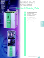
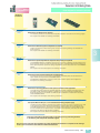
SIMOREGTM 6RA70 DC MASTER
Overview
6RA70
DC MASTER
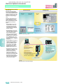
Introduction
■ A word about Siemens
Siemens AG
1
The parent company of Siemens Energy & Automation is
Siemens AG, headquartered in
Munich, Germany. Various Siemens divisions provide a broad
spectrum of products, systems, and services worldwide.
These include:
electronic components, medical electronics, power engineering, and automation
products and systems, as well
as public and private telecommunications networks.
Siemens’ worldwide sales exceed $75 billion in 2001, ranking it among the world’s largest
electrical companies. Siemens
ranks second in manufacturing. Siemens employs approximately 480 000 people in 193
countries, 500 manufacturing
facilities in 50 countries on 6
continents. A leading edge
company, Siemens annually
reinvests between 8 – 10 % of
sales in research and development activities, ranking in the
number one position in this category, along with companies
like Intel.
Siemens Energy &
Automation, Inc.
One of the largest Siemens
companies in the U.S. is Siemens Energy & Automation, Inc.
with over 12 000 employees and
annual sales in excess of $2 billion.
Siemens Energy & Automation
is headquartered near Atlanta,
Georgia and has 28 U.S. manufacturing facilities. SEA’ s facilities throughout the U.S. manufacture, market, and service a
wide variety of electrical and
electronic equipment and systems that protect, regulate, control, distribute electric power,
convert electric power to mechanical energy, and automate
various manufacturing and
industrial processes. SEA
produces 85 % of its products
domestically, and markets them
worldwide.
Siemens U.S.A.
The Siemens family of more
than twenty companies, subsidiaries, affiliates, and joint
ventures in the United States is
well established and growing
with annual sales in excess of
$16.2 billion. Siemens employs
more than 85 000 people in the
U.S., in ninety-three domestic
manufacturing facilities and
more than two-hundred thirty
sales and service locations.
1/2
Siemens DC Drives Catalog · 2006
Siemens Energy & Automation
products are sold in two general
market segments:
industrial and construction. Our
business units are organized
into four primary operating divisions:
Strategic Machinery Division,
Process Industries Division,
Industrial Products
Division, and Industrial
Services Division.
Strategic Machinery Division
business unit
The Strategic Machinery Division develops, engineers, manufactures, markets, and
services adjustable speed drive
and automation products. Our
adjustable speed drive and automation products are among
the finest in the world. Siemens
DC drives have historically offered consistently superior performance and high quality, due
to our commitment to continuous improvement in product
technologies and production
processes.
■ How the general information is
organized
General information
Welcome to Siemens
Siemens policies/protocols
Siemens return goods policy
Siemens repairs & returns for
warranty
Siemens technical services
Siemens emergency access
Standard terms and conditions
of sale
SIMOREG 6RA70 DC MASTER
Overview
6RA70
DC MASTER
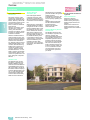
■ Welcome to Siemens US
If you are a new Siemens Drive
Products customer, we thank
you for doing business with us.
We will work hard to earn your
trust and serve your company
as if it were our own! If you are
currently doing business with
us, we thank you for the opportunity to grow with you.
Your primary contact point in
the United States for the 6RA70
DC MASTER and all other
Siemens drive products are the
Regional Sales Offices in the
following locations:
Customer service United States
Atlanta
5405 Metric Place
Suite 100
Norcross, GA 30092
Phone: 7 70-4 52-34 00
Fax: 6 78-2 97-84 09
■ Siemens policies/protocols
Minimum order
SE&A will assess a $25 handling fee on all orders valued at
less than $400.
Dallas
Freight
501 Fountain Parkway
2nd Floor
Grand Prairie, TX 75050
Phone: 8 17-6 40-49 29
Fax: 8 17-6 40-96 40
All of our original product
shipments are F.O.B. point of
shipment. For standard product
orders greater than $1 000 shipping from SE&A distribution
centers, charges are freight allowed via method selected by
SE&A. For orders less than
$1 000, motors, and non-standard product freight charges
are pre-paid and added to the
invoice. All air freight charges
are the responsibility of the customer. Also, a customer account number is required for
third party billing of freight
charges.
Chicago
1901 N. Roselle Road
Suite 210
Schaumburg, IL 60195
Phone: 8 00-3 33-77 32
Fax: 8 88-3 33-82 06
Houston
13105 NW Freeway
Suite 950
Houston, TX 77040
Phone: 7 13-6 90-30 00
Fax: 7 13-6 90-12 10
Kansas City
6201 College Blvd
Suite 385
Overland Park, KS 66211
Phone: 9 13-4 98-42 00
Fax: 9 13-4 98-42 40
Los Angeles
10655 Business Center Dr
Suite C1
Cypress, CA 90630
Phone: 7 14-2 52-30 00
Fax: 7 14-5 27-72 30
Philadelphia
323 Norristown Road
Suite 210
Amber, PA 19002
Phone: 8 00-3 88-80 67
Fax: 2 15-2 83-47 02
Emergency/Expedite fees
When customers require urgent
delivery, several methods of expedited delivery are available.
Each is noted below along with
the associated charges:
NEXT FLIGHT OUT –
This service provides same day
service where possible. In all
cases, the expedited surcharge
is $300. The customer is responsible for the associated
freight charges.
AFTER HOUR SERVICE –
Orders placed for same day
shipment after 5:00 pm eastern
time and weekends/holidays
are subject to a $300 surcharge. The customer is responsible for the associated
freight charges.
SPARE PARTS FROM INTERNATIONAL LOCATIONS –
Siemens Energy & Automation
supports all Siemens Drive
Products in the USA, regardless
of their country of origin. However, certain products may require
shipment from an international
emergency warehouse to meet
customer delivery requirements. In such cases the minimum order value for such items
is $300 net. If the order does not
total $300, an additional charge
will be added to bring the total
order to $300. (The normal $25
surcharge will not apply). Siemens features an international
emergency warehouse that can
ship many parts within 24 hours.
Most parts can arrive in the United States within 2 – 4 days. Your
Costomer Service or Sales Representative can check to see if
your part is in stock in the emergency warehouse.
CUSTOMER PICK UP –
All customer pick up orders will
be ready 2 hours after order is
received, and must be picked
up within 24 hours. There is no
additional charge for this service.
Returns
Standard products fall under
the SE&A standard product return guidelines (below). Drive
systems in cabinets, built to
specification, motors, or other
non-standard items do not fall
under this policy. Contact your
Sales or Customer Service Representative should you have
questions regarding return policy.
Siemens DC Drives Catalog · 2006
1/3
1
SIMOREG 6RA70 DC MASTER
Overview
6RA70
DC MASTER
Customer service United States
■ Siemens return goods policy
1
A Return Goods Request/
Authorization (RGA) is required
to accompany all products returned to Siemens Energy &
Automation, Inc. (Siemens).
This insures that the returned
product is properly identified
and credited to your account.
Unauthorized returns will be
refused and returned to the
customer with no liability to Siemens.
To provide our customers maximum opportunity for inventory
control, we have established
three classes of product returns:
• Accommodation return
• Siemens error return
• Non-Conforming product
warranty return
Product built to a customer’s
specifications cannot be returned for credit or exchange,
subject to return only when
material in Siemens’ opinion
has express economic value
for potential resale. If returned
product is a result of error(s) on
the part of Siemens, a full credit
to your account will be allowed
including freight charges. All
other returns, freight and handling will be prepaid by customer.
In all cases except when alleged personal injury/product
liability is involved, your account will be credited and a
credit memo will be issued
within 15 working days from
receipt of material. Credit is
determined either from the
original invoice if referenced,
or current stock pricing – less
restocking charges, cash discount application and repack-
1/4
aging fees where applicable.
Shipments returned without
referencing a returned goods
authorization (RGA) number will
be refused by Siemens.
Siemens reserves the right to
rebill within 90 days from our
receipt of material based on
results of a physical inspection
of the product.
All claims for loss, damage or
delays in transit are to be transacted by the consignee directly
with the carrier. The issuance of
this RETURN GOODS
AUTHORIZATION shall not be
construed as an acceptance of
any responsibility or liability on
the part of the Company or as a
waiver of any right to make a determination as to the Company’s
responsibility.
Return goods authorizations will
be automatically cancelled and
have no further effect unless the
returned goods are received by
the Company within 60 days after the date of issuance.
Accommodation return
Accommodation returns provide Siemens customers the
opportunity to return product ordered in error or in excessive
quantities. Products eligible for
return must be of current design
and revision level, unopened,
unused, undamaged, in the
original “as-shipped” package
and securely packed to be
received by Siemens without
damage. Software may only
be returned when the seal has
not been broken. Customized,
engineered and/or energized
products may not be returned
without prior approval and in
Siemens’ opinion have express
economic value for potential
resale.
Siemens DC Drives Catalog · 2006
Accommodation returns are
subject to a 10 % restocking
charge. If cleaning or repackaging is necessary, an additional
15 % per item repackaging
charge will be deducted from
any credit issued. After inspection of the returned product,
your account will be credited for
the full invoice value of the merchandise, less applicable
charges.
Customer should not deduct
credit for products returned
from payments. Credit will be
processed within 15 days of receipt of material. The customer
is responsible for costs, including freight and handling, for
returned product to Siemens.
Siemens error return
Siemens error returns provide
customers the opportunity to
return material within 60 days
of shipment in the event of a
Siemens order or shipment
error. Original purchase order,
invoice number and date must
be referenced. Products must
be unopened, unused, undamaged, in the original “asshipped” package or in static
protection, and securely
packed to be received by Siemens without damage. Software
may only be returned when seal
has not been broken.
A return goods authorization
(RGA) number will be issued as
authorization to return the product(s) to Siemens. After receipt
and inspection of the returned
product, a credit will be issued
for the full invoice value of the
merchandise, or a replacement
part provided. If the returned
product(s) packaging is
deemed not saleable, a 15 %
per item charge will be deducted from the credit issued.
Product should be returned collect by a Siemens approved
freight carrier or freight charges
may be assessed. Freight
charges will be credited if the
entire shipment is returned due
to Siemens error.
Non-Conforming product
warranty return
Non-Conforming product warranty returns enable Siemens
customers to return product to
the factory for replacement, exchange or credit if found to be
non-conforming in accordance
with the conditions of the Company’s product warranty.
It is at Siemens discretion
whether to replace, repair or issue a credit for non-conforming
products. The warranty at no
cost is conditional, and will
be determined by a technical
validation of the warranty once
the non-conforming item is received in our repair department
or authorized service center.
Please note, if you should fail to
return the non-conforming part
within 10 days upon instructions
from Siemens, you will be invoiced in full for the replacement part.
Product should be returned collect by a Siemens approved
freight carrier, or freight charges may be assessed.
SIMOREG 6RA70 DC MASTER
Overview
6RA70
DC MASTER
■ Siemens return goods
process – Accomodation
A Return Goods Request/
Authorization (RGA) is required
to accompany all products returned to Siemens. This insures
that the returned product is
properly identified and credited to your account. Unauthorized returns will be refused
and returned to the customer
with no liability to Siemens.
Accommodation return
Accommodation returns provide Siemens customers the
opportunity to return product
ordered in error or in excessive
quantities.
Procedures
A. Customer contacts Customer Service or inside sales
person to initiate return of
material.
B. Products must be unopened,
unused, undamaged, in the
original “as-shipped” package or in static protection,
and securely packed to be
received by Siemens without
damage. Software may only
be returned when seal has
not been broken.
C.Siemens Energy & Automation will process your request and a return goods
authorization (RGA) number
will be issued as authorization to return the product(s)
to Siemens.
D.A copy of your approved
RGA and shipping instructions will be faxed to you.
E. Customer ships product to
designated Siemens location. A Return Goods Request/Authorization (RGA)
is required to accompany
all material returned to
Siemens.
F. The customer is responsible
for costs, including freight
and handling, for returned
product to Siemens.
G.For all material returned in
conformance with this policy, a credit will be issued
promptly by Siemens within
15 days of receipt of material.
H.Customers should not take a
deduction for material returned until Siemens has issued the above mentioned
credit.
I. All returned materials are
subject to inspection by
Siemens. Returns not complying with this policy will be
returned to their sending location.
Customer service United States
J. Stock products are subject to
a 10 % restocking charge.
Customized and engineered
products are subject to a negotiated restocking charge.
K. An additional 15 % re-packaging charge will be applied
for returned material not suitable for resale, or returned in
broken inner cartons requiring inspection and re-packaging. No re-packaging
charge of any kind will be
applied when material is returned in undamaged, original inner/outer cartons
suitable for resale.
■ Siemens return goods
process – Siemens error
A Return Goods Request/
Authorization (RAG) is required
to accompany all products returned to Siemens. This insures
that the returned product is
properly identified and credited
to your account. Unauthorized
returns will be refused and returned to the customer with no
liability to Siemens.
Siemens error return
Siemens error returns provide
customers the opportunity to
return material within 60 days
of shipment in the event of a
Siemens order or shipment error.
Procedures
A. Customer contacts Customer
Service or inside sales person
to initiate return of material.
Original purchase order number or invoice number must
be available for reference.
B. Products must be unopened,
unused, undamaged, in the
original “as-shipped” package or in static protection,
and securely packed to be
received by Siemens without
damage. Software may only
be returned when seal has
not been broken.
C.Siemens will process your
request and a return goods
authorization (RGA) number
will be issued as authorization
to return the product(s) to
Siemens.
D.A copy of your approved
RGA and shipping instructions will be faxed to you.
E. Customer ships product to
designated Siemens location.
A Return Goods Request/Authorization (RGA) is required
to accompany all material
returned to Siemens.
F. Material should be returned
following the Routing/Preferred Carrier instructions
located on the shipping instructions. If these instructions are not followed freight
charges may be assessed.
G.For all material returned in
conformance with this policy,
a credit will be issued by within 15 days of receipt of material or a replacement part
provided.
H.Customers should not take
a deduction for material returned. Siemens will issue a
credit within 15 days of receipt of material.
I. All returned materials are subject to inspection by Siemens.
Returns not complying with
this policy will be returned to
their sending location.
J. An additional 15 % re-packaging charge will be applied
for returned material not suitable for resale, or returned in
broken inner cartons requiring inspection and re-packaging. No re-packaging
charge of any kind will be
applied when material is returned in undamaged, original inner/outer cartons
suitable for resale.
■ Siemens return goods
process – Non-Conforming
(Warranty)
A Return Goods Request/
Authorization (RAG) is required
to accompany all products returned to Siemens. This insures
that the returned product is
properly identified and credited
to your account. Unauthorized
returns will be refused and returned to the customer with no
liability to Siemens.
Non-Conforming product
return (Drives)
Non-Conforming product warranty returns enable Siemens
customers to return product to
the factory for replacement, exchange or credit if found to be
non-conforming in accordance
with the conditions of the Company’s product warranty.
C.If the return is an emergency,
e.g. your equipment is down,
and the warranty can be validated commercially, for approved product categories
Siemens will ship a replacement part to you at no charge.
If you should fail to return the
non-conforming part within
10 days upon instructions
from Siemens, you will be invoiced in full for the replacement part.
D.A copy of your approved
RGA and shipping instructions will be faxed to you.
E. Customer ships product to
designated Siemens location.
A Return Goods Request/Authorization (RGA) is required
to accompany all material
returned to Siemens.
F. Material should be returned
following the Routing/Preferred Carrier instructions
located on the shipping instructions. If these instructions are not followed freight
charges may be assessed.
G.Conforming products will be
shipped back to the customer.
H.For all material returned in
conformance with this policy,
a credit will be issued by
Siemens after an evaluation
of the received material or a
replacement part provided.
I. Customers should not take a
deduction for material returned.
J. All returned materials are subject to inspection by Siemens.
Returns not complying with
this agreement will be returned to their sending location.
Procedures
A. Customer contacts Technical
Support (1-8 00-3 33-74 21) to
initiate return of material. A list
of products requested to
return and alleged failure
scenarios are communicated
to Siemens for processing.
B. Siemens will process your
request and a return goods
authorization (RGA) number
will be issued as authorization
to return the product(s) to
Siemens.
Siemens DC Drives Catalog · 2006
1/5
1
SIMOREG 6RA70 DC MASTER
Overview
6RA70
DC MASTER
Customer service United States
■ Optional warranties
Repair, replacement, and
warranty service
1
All claims for warranty repair or
replacement must initially be
made to Drives Technical Service at 1-8 00-3 33-74 21.
Should the problem not be
solved over the phone, an RGA
will be issued to return the
defective part. If the warranty
can be validated commercially
(ship date falls within warranty
period) a replacement part can
be shipped if available. SE&A
will pay for best way freight on
such replacements. The customer is responsible for expedited freight delivery.
Once the defective product
has been returned, a technical
evaluation will be performed to
validate the warranty. Should
the unit be found to not meet
warranty requirements, and
purchase order will be requested from the customer.
If your warranty has expired,
you may still want to take advantage of our excellent repair
and replacement service.
Highly trained technicians perform incoming tests to determine the exact failure, repair
the equipment, and fully test
prior to shipment back to the
customer. However, if you
elect, we may be able to send
you a remanufactured part for
60 % of the list price of a new
part less your applicable discount on an exchange basis.
Remanufactured parts carry a
ninety (90) day warranty. Your
Sales or Customer Service
Representative can tell you
which parts are included in our
repair and replacement program. Should you take advanMonths from
Standard
warranty
tage of this program, please
note that the original part must
be returned to SE&A within ten
(10) days, or an invoice will be
issued for the additional 40 %.
Replacement warranty
Should a remanufactured replacement of a defective item
be the solution to a warranty
claim, the remanufactured part
shall be under warranty for the
duration of the warranty of the
original item or ninety (90) days,
whichever is longer. A remanufactured part (other than original
warranty replacement) carries a
ninety (90) day warranty.
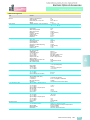
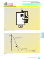
Extended warranty
Drive products offers an extended warranty for all products
sold. An extended warranty of
12 months is offered with a surcharge of 5 % of the net price
of the product. This extended
warranty offer is only available if
ordered prior to time of original
shipment from Siemens.
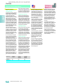
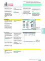
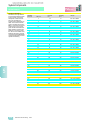
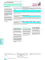
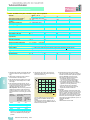
Deferred warranty
Siemens also offers a deferred
warranty for all products sold.
Commissioning must also be
purchased to inspect the condition of the drive and supervise
the start up. This deferred warranty offer is only available if
ordered prior to time of original
shipment from Siemens. The
deferred warranty is offered for
those applications that will have
a delayed installation period,
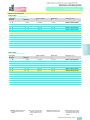
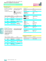
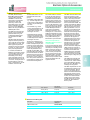
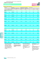
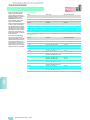
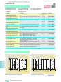
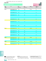
but only require a 12 month warranty from the date of commissioning. The chart below is a
listing of the warranty periods
and fees for the deferred warranty and the extended warranty programs.
6 month
deferred
warranty
12 month
deferred
warranty
Installation
12
12
12
Manufacturing
18
24
30
% of net
0%
1%
2%
1/6
Siemens DC Drives Catalog · 2006
■ Siemens technical services ■ Siemens emergency access
The Technical Service Group is
responsible for technical service support for customers, field
service, and sales engineers.
Requests for parts, equipment
commissioning, emergency
service, or routine maintenance
are coordinated and scheduled
through this group.
Service coordination and technical support for a wide variety
of drive products, including
both domestic and international
supplied units, are available
from this team. Interfacing with
the Siemens Service Organization, other Siemens Divisions,
and supplier service facilities,
this group is the single point of
contact in effectively providing
remote technical and field service support.
Over the past year, an internal
survey showed that greater than
95 % of the problems called in
were resolved over the telephone. This level of technical
expertise has significantly reduced the number of on-site
service calls.
Technical Service is available
24-hours, 7 days a week by dialing 1-8 00-3 33-74 21; ask for
Drives Technical Services and
the call will be channeled automatically through a call center
which activates the appropriate
personnel for both parts and
technical support.
The Drive Products Business
Unit has an emergency spare
parts depot at Atlanta Hartsfield
International Airport. Same day
delivery requirements are often
serviced out of this Depot as
well as after hour shipments
including weekends and holidays. This has allowed us to
expedite emergency shipment,
saving several hours in the
process.
To activate our Emergency/
After Hours Service, simply dial
1-8 00-3 33-74 21 and ask for
Drives Technical Service and
the call will be automatically
transferred to our message service, who will in turn page the
On-Call Representative.
Tell the operator there is an
emergency and you would like
to contact after hour’s personnel
for spare parts or technical
service, and we will return your
call immediately.
SIMOREG 6RA70 DC MASTER
Overview
6RA70
DC MASTER
Customer service United States
■ Standard terms and conditions of sale (9/1/2001)
Siemens Energy & Automation, Inc. ("Seller")
1. WARRANTY
(a) Seller warrants that on the date of shipment the goods are of the kind and
quality described herein and are free of nonconformities in workmanship and
material. This warranty does not apply to goods delivered by Seller but manufactured by others.
(b) Buyer's exclusive remedy for a nonconformity in any item of the goods shall
be the repair or the replacement (at Seller's option) of the item and any affected
part of the goods. Seller's obligation to repair or replace shall be in effect for
a period of one (1) year from initial operation of the goods but not more than
eighteen (18) months from Seller's shipment of the goods, provided Buyer
has sent written notice within that period of time to Seller that the goods do
not conform to the above warranty. Repaired and replacement parts shall be
warranted for the remainder of the original period of notification set forth
above, but in no event less than 12 months from repair or replacement. At its
expense, Buyer shall remove and ship to Seller any such nonconforming
items and shall reinstall the repaired or replaced parts. Buyer shall grant Seller access to the goods at all reasonable times in order for Seller to determine
any nonconformity in the goods. Seller shall have the right of disposal of
items replaced by it. If Seller is unable or unwilling to repair or replace, or if
repair or replacement does not remedy the nonconformity, Seller and Buyer
shall negotiate an equitable adjustment in the contract price, which may include a full refund of the contract price for the nonconforming goods.
(c) SELLER HEREBY DISCLAIMS ALL OTHER WARRANTIES, EXPRESS OR
IMPLIED, EXCEPT THAT OF TITLE. SPECIFICALLY, IT DISCLAIMS THE
IMPLIED WARRANTIES OF MERCHANTABILITY, FITNESS FOR A PARTICULAR PURPOSE, COURSE OF DEALING AND USAGE OF TRADE.
(d) Buyer and successors of Buyer are limited to the remedies specified in this
article and shall have no others for a nonconformity in the goods. Buyer
agrees that these remedies provide Buyer and its successors with a minimum adequate remedy and are their exclusive remedies, whether Buyer's or
its successors' remedies are based on contract, warranty, tort (including
negligence), strict liability, indemnity, or any other legal theory, and whether
arising out of warranties, representations, instructions, installations, or nonconformities from any cause.
(e) Note: This article 1 does not apply to any software which may be furnished
by Seller. In such cases, the attached Software License Addendum applies.
2. PATENTS
Seller shall pay costs and damages finally awarded in any suit against Buyer or
its vendees to the extent based upon a finding that the design or construction of
the goods as furnished infringes a United States patent (except infringement occurring as a result of incorporating a design or modification at Buyer's request),
provided that Buyer promptly notifies Seller of any charge of infringement, and
Seller is given the right at its expense to settle such charge and to defend or control the defense of any suit based upon such charge. Seller shall have no obligation hereunder with respect to claims, suits or proceedings, resulting from or
related to, in whole or in part, (i) the use of software or software documentation,
(ii) compliance with Buyer's specifications, (iii) the combination with, or modification of, the goods after delivery by Seller, or (iv) the use of the goods, or any
part thereof, in the practice of a process. THIS ARTICLE SETS FORTH SELLER'S
ENTIRE LIABILITY WITH RESPECT TO PATENTS.
3. PERFORMANCE; DELAYS
Timely performance by Seller is contingent upon Buyer's supplying to Seller,
when needed, all required technical information and data, including drawing approvals, and all required commercial documentation. If Seller suffers delay in
performance due to any cause beyond its reasonable control, the time of performance shall be extended a period of time equal to the period of the delay and
its consequences. Seller will give to Buyer notice within a reasonable time after
Seller becomes aware of any such delay.
4. SHIPMENT, TITLE AND RISK OF LOSS
Unless the delivery terms of this contract expressly provide for F.O.B. destination, shipping/delivery will be F.O.B. Seller's point of shipment with title to the
goods and risk of loss or damage passing to Buyer at that point. Buyer will be
responsible for shipment during transit and for filing any damage or loss claims
directly with the carrier. Seller may make partial shipments.
5. TAXES
Any applicable duties or sales, use, excise, value-added or similar taxes will be
added to the price and invoiced separately (unless an acceptable exemption
certificate is furnished).
6. TERMS OF PAYMENT
(a) Unless otherwise stated, all payments shall be in United States dollars, and
a pro rata payment shall become due as each shipment is made. If shipment
is delayed by Buyer, date of notice of readiness for shipment shall be
deemed to be date of shipment for payment purposes.
(b) On late payments, the contract price shall, without prejudice to Seller's right
to immediate payment, be increased by 1 1/2 % per month on the unpaid balance, but not to exceed the maximum permitted by law.
(c) If any time in Seller's judgment Buyer is unable or unwilling to meet the terms
specified, Seller may require satisfactory assurance or full or partial payment
as a condition to commencing or continuing manufacture or making shipment, and may, if shipment has been made, recover the goods from the carrier, pending receipt of such assurances.
7. NONCANCELLATION
Buyer may not cancel or terminate for convenience, or direct suspension of manufacture, except with Seller's written consent and then only upon terms that will
compensate Seller for its engineering, fabrication and purchasing charges and
any other costs relating to such cancellation, termination or suspension, plus a
reasonable amount for profit.
8. NUCLEAR
Buyer represents and warrants that the goods covered by this contract shall not
be used in or in connection with a nuclear facility or application. If Buyer is unable to make such representation and warranty, then Buyer agrees to indemnify
and hold harmless Seller and to waive and require its insurers to waive all right
of recovery against Seller for any damage, loss, destruction, injury or death
resulting from a "nuclear incident", as that term is defined in the Atomic Energy
Act of 1954, as amended, whether or not due to Seller's negligence.
9. LIMITATION OF LIABILITY
Neither Seller, nor its suppliers shall be liable, whether in contract, warranty,
failure of a remedy to achieve its intended or essential purposes, tort (including
negligence), strict liability, indemnity or any other legal theory, for loss of use,
revenue or profit, or for costs of capital or of substitute use or performance,
or for indirect, special, liquidated, incidental or consequential damages, or for
any other loss or cost of a similar type, or for claims by Buyer for damages of
Buyer's customers. Seller's maximum liability under this contract shall be the
contract price. Buyer and Seller agree that the exclusions and limitations set
forth in this article are separate and independent from any remedies which
Buyer may have hereunder and shall be given full force and effect whether or not
any or all such remedies shall be deemed to have failed of their essential purpose.
10. GOVERNING LAW AND ASSIGNMENT
The laws of the State of Georgia shall govern the validity, interpretation and enforcement of this contract, without regard to its conflicts of law principles. The
application of the United Nations Convention on Contracts for the International
Sale of Goods shall be excluded. Assignment may be made only with written
consent of both parties; provided, however, Seller may assign to its affiliate without Buyer's consent.
11. ATTORNEY FEES
Buyer shall be liable to Seller for any attorney fees and costs incurred by Seller
in enforcing any of its rights hereunder.
12. DISPUTES
Either party may give the other party written notice of any dispute arising out of
or relating to this contract and not resolved in the normal course of business. The
parties shall attempt in good faith to resolve such dispute promptly by negotiations between executives who have authority to settle the dispute. If the matter
has not been resolved within 60 days of the notice, either party may initiate nonbinding mediation of the dispute.
13. STATUTE OF LIMITATIONS
To the extent permitted by applicable law, any lawsuit for breach of contract,
including breach of warranty, arising out of the transactions covered by this contract, must be commenced not later than twelve (12) months from the date the
cause of action accrued.
14. PRICES
In the event of a price increase or decrease, the price of goods on order will be
adjusted to reflect such increase or decrease. This does not apply to a shipment
held by request of Buyer. Goods already shipped are not subject to price increase or decrease. Orders on a bid or contract basis are not subject to this
article. Seller's prices include the costs of standard domestic packing only. Any
deviation from this standard packing (domestic or export), including U.S. Government sealed packing, will result in extra charges. To determine such extra
charges, consult Seller's sales offices. Orders of less than $400 will be charged
a $25 handling fee.
15. ADDITIONAL TERMS OF PAYMENT
(a) Invoice payment terms are as shown on latest discount sheets as issued
from time to time. Cash discounts are not applicable to notes or trade acceptances, to prepaid transportation charges when added to Seller's invoices or to discountable items if there are undisputed past due items on the
account. Portions of an invoice in dispute should be deducted and the balance remitted with a detailed explanation of the deduction. Cash discounts
will only be allowed on that portion of the invoice paid within the normal discount period.
(b) Freight will be allowed to any common-carrier free-delivery point within the
United States, excluding Alaska and Hawaii, on shipments exceeding $1 000
net or more providing Seller selects the carrier. On shipments to Alaska and
Hawaii, freight will be allowed to dockside at the listed port of debarkation
nearest the destination point on shipments of $1 000 net or more. Buyer shall
pay all special costs such as cartage, stevedoring and insurance. Special
freight allowances are as shown on latest discount sheets as issued from
time to time. Cataloged weights are estimated, not guaranteed. Seller assumes no responsibility for tariff classifications on carriers.
16. CHANGES IN LAWS AND REGULATIONS
Seller's prices and timely performance are based on all applicable laws, rules,
regulations, orders, codes, standards or requirements of governmental authorities effective on the date of Seller's proposal. Any change to any law, rule,
regulation, order, code, standard or requirement which requires any change
hereunder shall entitle Seller to an equitable adjustment in the prices and any
time of performance.
Siemens DC Drives Catalog · 2006
1/7
1
SIMOREG 6RA70 DC MASTER
Overview
6RA70
DC MASTER
Customer service Canada
■ Welcome to Siemens
Canada Ltd.
1
As a subsidiary of Siemens AG,
Siemens in Canada draws on
the global network of innovation to generate revenues of
more than $2 billion. Good
news for our economy and our
way of life. From its corporate
headquarters in Mississauga,
Ontario, Siemens employs
6 300 Canadians coast to
coast, developing solutions for
the entire country. And exporting solutions around the world,
in the amount of 60 % of Canadian production.
■ Siemens after sales support
Call 1-8 88-3 03-33 53 for technical service, spare parts,
return material authorisations
and warranty issues.
Customer Interaction Centre
for after sales support:
provides a national, 24-hours,
7 days a week, bilingual service to respond to all customer
calls involving return material
authorisations, service requests, spare parts orders and
warranty issues as well as
product comments. The Customer Interaction Centre can
also be contacted via email at
[email protected].
■ Siemens technical service
Siemens technical services
support all Siemens drives in
Canada. Throughout Canada
Siemens technical services
provide technical service support and fields service.
Request for equipment commissioning, emergency service, and routine maintenance
are coordinated and scheduled through this group. If technical service is required,
please call 1-8 88-3 03-33 53.
With over a hundred years’ experience in providing reliability,
safety, and service, Siemens is
there.
1/8
■ Siemens repairs and returns
In case a defective part needs
to be returned to Siemens
Canada Ltd. for repair or credit,
please follow these instructions.
Parts sent to Siemens Canada
Ltd. not using the procedures
outlined below may cause the
warranty to be voided or improper credit to be issued.
1. Call 1-8 88-3 03-33 53 and ask
for warranty/defective product returns. The call will be
forwarded to the next available Customer Service Representative (CSR). The CSR
will provide instruction about
how to complete a Field
Inspection Report & RMA
Request Form (FIR&RMA)
with the following important
information. The FIR&RMA
form shall be faxed to the advised address on the form.
a) Company name, contact
address
b) Original purchase order
number
c) Model number
d) Serial number
e) Detailed fault description
2. A Return Material Authorization form (RMA) will be issued
within 24 hours of receipt of
your FIR&RMA. The copy of
RMA form must accompany
the listed items being returned to Siemens. Any item
received without the appropriate RMA documentation
will not be accepted and returned to the sender collect.
RMA’s are valid for 30 days
from date issued. Any returns
received after 30 days will be
returned to the sender at their
expense. A new RMA will
have to be requested for the
same items before being returned.
Siemens DC Drives Catalog · 2006
3. Electrostatically Sensitive
Devices (ESD) handling is to
be observed for all electronicbased products. Please use
anti-static bags when shipping printed circuit boards
back to Siemens. Otherwise
the warranty is null or void.
4. If it is a warranty claim, the
item will be inspected and
the warranty validated, upon
receipt. Then the item will be
repaired or replaced as appropriate and will be returned
at no charge.
5. If it is a non-warranty case,
an inspection fee will be
charged to cover the cost of
evaluating the defective return for possible repair work.
The item will be inspected
and the CSR will issue a quotation for repair. Upon receipt
or Purchase Order, the item
will be repaired, tested and
returned.
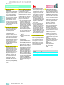
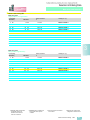
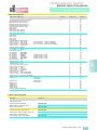
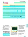
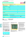
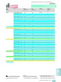
■ Siemens extended warranty
Drive products offer an extended warranty for all products
sold. The extended warranty
of 12 months is offered with a
surcharge of 5 % of the net
price of the product. This extended warranty is only available if ordered prior to time of
shipment from Siemens.
■ Siemens technical training
The Siemens technical training
centre is committed to providing
quality technical courses in the
Canadian Electrical and Automation Markets. Siemens develops and gears each course and
the related materials to be effective in the competitive Canadian
marketplace.
Siemens offers 20 quality courses with expert instructors and
dedicated support staff. Our
practical, but challenging
“hands-on” courses provide the
ultimate arena for effective
learning and information retention. Training is offered in St.
Johns, Dartmouth, Montreal,
Mississauga, Calgary, Edmonton, and Vancouver. Custom onsite training tailored to customer
requirements and specific requests are also performed.
Following each course, the students can feel confident that
they are equipped with the expert knowledge and capabilities
to effectively sell or support the
product.
Registration or questions on
course content can be made to
the Training Centre by the following:
Elizabeth Isaac
Training Administrator
Tel.: 9 05-8 19-58 00 Ext. 22 19
Fax: 9 05-8 19-58 22
Email:
[email protected]
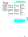
Months from
Standard warranty
Extended warranty
Installation
12
24
Manufacturing
18
30
% of net
0%
5%
SIMOREG 6RA70 DC MASTER
Overview
6RA70
DC MASTER
Customer service Canada
■ General terms and conditions of sale
The following terms and conditions of sale shall apply to any sale of goods and services by Siemens Canada Limited (hereinafter called "Siemens"). Purchaser shall be
deemed to have full knowledge of the terms and conditions herein and such terms
and conditions shall be binding if either the goods and services referred to herein
are delivered to and accepted by Purchaser, or if Purchaser does not within five days
from the date hereof deliver to Siemens written objection to said terms and conditions or any part thereof.
1. GENERAL
In the event of any conflict or inconsistency between the terms and conditions of
sale herein and the terms and conditions contained in Purchaser's order or in
any other form issued by Purchaser, whether or not any such form has been
acknowledged or accepted by Siemens, Siemens' terms and conditions herein
shall prevail. No waiver, alteration or modification of these terms and conditions
shall be binding upon Siemens unless made in writing and signed by a duly
authorized representative of Siemens.
9. LIABILITY
Siemens shall not be liable for and shall be held harmless by Purchaser from any
damage, losses or claims of whatever kind, contractual or delictual, consequential or incidental, direct or indirect, arising out of, in connection with or resulting
from the sale governed hereby or the goods, including, but without limitation, the
manufacture, repair, handling, installation, possession, use, operation or dismantling of the goods and any and all claims, actions, suits, and proceedings
which may be instituted in respect to the foregoing.
3. PRICES/COST OF TRANSPORTATION
All quoted prices are based on the current exchange rates, tariffs and costs of
manufacture. Unless otherwise stated in the quotation, quoted prices are subject
to change by Siemens with or without notice until Purchaser's acceptance. Prices are subject to correction for error. Unless otherwise stated, all prices are f.o.b.
factory and include domestic packing. Customary methods of transportation
shall be selected by Siemens and such transportation will be at Purchaser's expense. Special methods of transportation will be used upon Purchaser's request
and at Purchaser's additional expense provided reasonable notice of Purchaser's transportation requirements are given by Purchaser to Siemens prior to shipment.
10. WARRANTY
Goods sold hereunder are covered by a warranty against defects in material and
workmanship provided the goods and services are subjected to normal use and
service. The applicable warranty period is twelve (12) months from the date of installation or eighteen (18) months from shipping date to Purchaser of any item of the
goods, whichever occurs first, or any other warranty period otherwise stipulated
in writing by Siemens under this sale. For components not supplied by Siemens, the
original manufacturer's warranty shall apply to the extent assignable by Siemens.
The obligation under this warranty is limited to the repair or replacement, at Siemens' option, of defective parts f.o.b. point of shipment provided that prompt notice
of any defect is given by Purchaser to Siemens in writing within the applicable
warranty period and that upon the Purchaser's return of the defective parts to
Siemens or, if designated by Siemens, to the location where the works are made,
properly packed and with transportation charges prepaid by Purchaser, an inspection thereof shall reveal to Siemens' satisfaction that Purchaser's claim is valid
under the terms of this warranty. Purchaser shall assume all responsibility and expense for dismantling, removal, re-installation and freight in connection with the
foregoing. The same obligations and conditions extend to replacement parts furnished by Siemens hereunder. Siemens does not assume liability for installation,
labour or consequential damages. Siemens makes no warranty other than the one
set forth herein. All other warranties, legal, expressed or implied, including but
not limited to any expressed or implied warranty of merchantability, of fitness for
the intended use thereof or against infringement are hereby expressly excluded.
4. TAXES
Prices do not include Goods & Services Tax, Provincial or Municipal sales, use,
value-added or similar tax. Accordingly, in addition to the price specified herein,
the amount of any present or future sales, use, value-added or similar tax applicable to the sale of the goods hereunder to or the use of such goods by Purchaser shall be paid by Purchaser to the entire exoneration of Siemens.
The applicable warranty ceases to be effective if the goods are altered or repaired other than by persons authorized or approved by Siemens to perform
such work. Repairs or replacement deliveries do not interrupt or prolong the term
of the warranty. The warranty ceases to be effective if Purchaser fails to operate
and use the goods sold hereunder in a safe and reasonable manner and in accordance with any written instructions from the manufacturers.
5. DELIVERY
Delivery schedules are approximate and are based on prevailing market conditions applicable respectively at the time of Siemens' quotation and Siemens' acceptance of Purchaser's order. Delivery shall also depend on the prompt receipt
by Siemens of the necessary information to allow maintenance of the manufacturer's engineering and manufacturing schedules. Siemens may extend delivery
schedules or may, at its option, cancel Purchaser's order in full or in part without
liability other than to return any deposit or prepayment which is unearned by reason of the cancellation.
11. INSTALLATION
Unless otherwise expressly stipulated, the goods shall be installed by and at the
risk and expense of Purchaser. In the event that Siemens is requested to supervise such installation, Siemens' responsibility shall be limited to exercising that
degree of skill customary in the trade in supervising installations of the same
type. Purchaser shall remain responsible for all other aspects of the work including compliance with the local regulations.
2. QUOTATIONS
Unless otherwise stated, Siemens' quotation shall be null and void unless
accepted by Purchaser within thirty (30) days from the date of quotation.
6. FORCE MAJEURE
Siemens shall not be responsible or liable for any loss or damage incurred
by Purchaser herein resulting from causes beyond the reasonable control
of Siemens including, but without limitation, acts of God, war, invasion, insurrection, riot , the order of any civil or military authority, fire, flood, weather,
acts of the elements, delays in transportation, unavailability of equipment
or materials, breakdown, sabotage, lock-outs, strikes or labour disputes, faulty
castings or forgings, or the failure of Siemens' suppliers to meet their delivery
promises. The acceptance of delivery of the equipment by Purchaser
shall constitute a waiver of all claims for loss or damage due to any delay
whatsoever.
7. SHIPMENT/DAMAGES OR SHORTAGES IN TRANSPORT/RISK
Except for obligations stated under "Warranty" herein, Siemens' responsibility for
goods ceases upon delivery to the carrier. In the event of loss or damage during
shipment, Purchaser's claim shall be against the carrier only. Siemens will,
however, give Purchaser any reasonable assistance to secure adjustment of
Purchaser's claim against the carrier provided immediate notice of such claim is
given by Purchaser to Siemens. Claims for shortages must be made in writing
within ten (10) days after receipt of goods by Purchaser. If Siemens does not
receive written notification of such shortages within such ten (10) days, it shall
be conclusively presumed that the goods were delivered in their entirety. Unless
agreed upon otherwise in writing, Siemens reserves the right to make partial
shipments and to submit invoices for partial shipments.
8. TITLE
Title to the goods or any part thereof shall not pass from Siemens to Purchaser
until all payments due hereunder have been duly made in cash, except as otherwise expressly stipulated herein. The goods shall be and remain personal or
moveable property, notwithstanding their mode of attachment to realty or other
property. If default is made in any of the payments herein, Purchaser agrees that
Siemens may retain all payments which have been made on account of the purchase price as liquidated damages, and Siemens shall be free to enter the premises where the goods may be located and remove them as Siemens' property,
without prejudice to Siemens' right to recover any further expenses or damages
Siemens may suffer by reason of such nonpayment.
12. RETURNED GOODS
No goods may be returned to Siemens without Siemens' prior written permission.
Siemens reserves the right to decline all returns or to accept them subject to a
handling/restocking charge. Even after Siemens has authorized the return of
goods for credit, Siemens reserves the right to adjust the amount of any credit
given to Purchaser on return of the goods based on the conditions of the goods
on arrival in Siemens' warehouse. Credit for returned goods will be issued to Purchaser only where such goods are returned by Purchaser and not by any subsequent owner of the goods. Goods will be considered for return only if they are
in their original condition and packaging.
13. TERMS OF PAYMENT
Unless otherwise stated, invoices on "open account" shipment are payable within thirty (30) days of invoice date. Unless specifically provided, no cash discount
shall be available to Purchaser. When cash discount is offered, the discount
price is computed from the date of invoice. Siemens does not offer cash discount
on C.O.D. shipments. Should payment not be made to Siemens when due, Siemens reserves the right, until the price has been fully paid in cash, to charge Purchaser with interest on such overdue payments at the rate of eighteen percent
(18 %) per annum. The charging of such interest shall not be construed as obligating Siemens to grant any extension of time in the terms of payment.
14. CHANGES AND CANCELLATION
Orders accepted by Siemens are not subject to changes or cancellation by
Purchaser, except with Siemens' written consent. In such cases where Siemens
authorizes changes or cancellation, Siemens reserves the right to charge
Purchaser with reasonable costs based upon expenses already incurred and
commitments made by Siemens, including, without limitation, any labour done,
material purchased and also including Supplier's usual overhead and reasonable profit and cancellation charges from Siemens' suppliers.
15. THE AGREEMENT
An acceptance and official confirmation of Purchaser's order by Siemens shall
constitute the complete agreement, subject to the terms and conditions of sale
herein set forth, and shall supersede all previous quotations, orders or agreements. The law of the Province of Ontario shall govern the validity, interpretation
and enforcement of these terms and conditions of sale and of any contract of
which these terms and conditions are a part.
Siemens DC Drives Catalog · 2006
1/9
1
SIMOREG 6RA70 DC MASTER
Overview
SIEMENS Family of Applied Drives
6RA70
DC MASTER
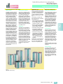
The Siemens Family
of Applied Drives
1
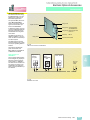
From stand-alone drives to
the most challenging applications Siemens applied
series drives offer a truly
integrated family of high
performance drives that
are unmatched from one
continent to the next.
SIMOVERT™
MASTERDRIVES VC
AC Series of Vector Control
1 HP to 5 000 HP
Customer-specific, integral
solutions are available for
the most varied of applications in all industrial sectors.
SIMOREG 6RA70
DC MASTER
7.5 HP – 1 000 HP at
500 V DC
Extended designs also
available up to 8 000 HP
SIMOVERT
MASTERDRIVES MC
Motion Control Series
0.5 HP to 355 HP
1/10
Siemens DC Drives Catalog · 2006
SIMOREG 6RA70 DC MASTER
Overview
6RA70
DC MASTER
SIMOREG History
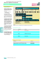
2000
SIMOREG 6RA70
DC MASTER
Giving DC a new lease on
life for the next millennium
Now with:
•More performance
•More HP selections
and extended
ranges
•More application
flexibility
•More communication
choices
•More favorably priced
solutions
1994
SIMOREG 6RA24
Known throughout
the industry as
“The Workhorse“
1986
3rd Generation SIMOREG
Among the first digital DC
drives in the market
1971
SIMOREG 6RA21
Analog DC Drive
The SIMOREG name is born
out of the Siemens line of DC
products
Siemens DC Drives Catalog · 2006
1/11
1
SIMOREG 6RA70 DC MASTER
Overview
6RA70
DC MASTER
Application
1
The SIMOREG 6RA70 converters are specifically designed
to provide precise DC motor
speed control over a wide
range of machine parameters
and load conditions. The
modular design that allows
them to be tailored exactly to
the application at hand also
lends them well to many nonstandard DC applications.
From a package drive to an
integral solution of the most
sophisticated project the
SIMOREG 6RA70 has proven
itself time and time again in
industries including:
• Metals
• Paper
The SIMOREG DC MASTER
series is completely uniform
with regard to
• Communication
• Technology
• BICO software platform
• Identical main board and
cardrack
• Operator control and
visualization
What this means is that if you
know one SIMOREG DC
MASTER you know them all.
And with our easy-to-use start
up tool (DriveMonitor) getting to
know your first drive could not
be easier.
• Textile
• Rubber
• Plastics
• Extruding
• Lifting, etc.
In addition to increased performance and extended
capabilities added into the
new SIMOREG 6RA70 the
standard model offerings
have been increased and extended up to 1 000 HP at 500 V
DC in the compact unit design. With the paralleling capabilities and high HP
designs extended ranges up
to 8 000 HP can be achieved.
1/12
Siemens DC Drives Catalog · 2006
Siemens‘ worldwide service
and sales network enable all
our customers to obtain direct
access to expert advice and
project planning as well as
training and service from
any part of the world.
SIMOREG 6RA70
DC MASTER
Drive Description
2/2
2/3
2/4
2/5
2/7
2/7
2/8
2/8
2/10
2/10
Design and mode of operation
SIMOREG 6RA70 converters
Parameterization
Software structure
Closed-loop functions in armature circuit
Closed-loop control functions in field circuit
Optimization run
Monitoring and diagnosis
Functions of inputs and outputs
Safety shutdown (E-STOP)
Serial interfaces
2/11
2/12
2/18
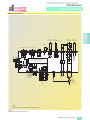
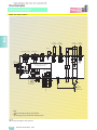
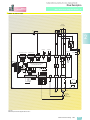
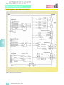
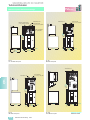
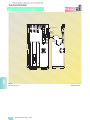
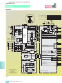
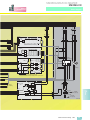
Power module block diagrams 6RA70..-6F
and 6RA70..-4G
15 A to 850 A
1180 A, 1660 A and 1680 A
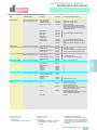
Terminal assignments
2/13
2/14
2/15
2/16
2/17
2/18
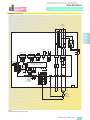
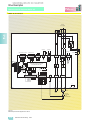
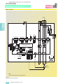
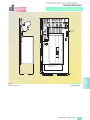
Base drive panel block diagrams 6RA70..-2F
15 A to 30 A
60 A to 255 A
430 A to 510 A
850 A
1180 A and 1660 A
Terminal assignments
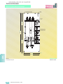
2/19
2/20
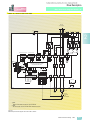
CUD1 Electronics board
CUD1 Block diagram
Terminal assignments CUD1
Siemens DC Drives Catalog · 2006
2/1
2
SIMOREG 6RA70 DC MASTER
Drive Description
6RA70
DC MASTER
Design and mode of operation
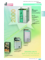
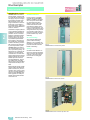
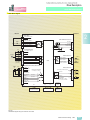
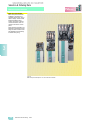
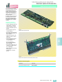
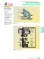
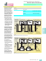
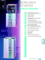
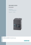
■ SIMOREG 6RA70 converters
SIMOREG 6RA70 converters
are fully digital, compact units
for connection to a three-phase
AC supply. They in turn supply
the armature and field of variable-speed DC motors. The
range of rated DC currents extends from 15 A to 3000 A in
the modular design. Higher HP
designs are also available from
2 700 A to 14000 A.
2
Converters for single-quadrant
or four-quadrant operation are
available to suit individual applications. As the converters
feature an integrated parameterization panel, they are autonomous and do not require
any additional parameterization equipment. All open-loop
and closed-loop control tasks
as well as monitoring and auxiliary functions are performed
by a microprocessor system.
SIMOREG 6RA70 converters
are characterized by their compact, space-saving design. An
electronics box containing the
closed-loop control board is
mounted in the converter door.
This box also has space to hold
additional boards for processrelated expansion functions
and serial interfaces. This design makes them especially
easy to service since individual
components are easily accessible.
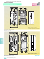
Customer Preference
For the purpose of versatility
and selection the SIMOREG
6RA70 is available in the base
drive and power module offering. The base drive panel
designs consist of the power
module mounted on a base
panel with the addition of line
fuses, control transformer, and
contactor. The base drive panel
designs allows for easy customer connection of the power cables to the supplied connection
points mounted on top of the
assembly.
US overload rating
The converters listed in this
guide contain a US rating
allowing a 150 % overload for
60 seconds. All base drive components have been selected
based on this rating.
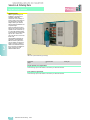
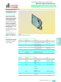
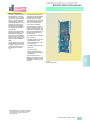
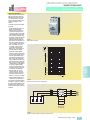
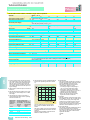
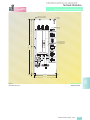
Fig. 2/1
SIMOREG 6RA70, 15 A Base drive panel
Cooling
Converters with rated DC currents up to 100 A are selfcooled,
while converters with rated DC
currents of 140 A and higher
have forced-air cooling (fan
assembly).
External signals (binary inputs/
outputs, analog inputs/outputs,
pulse encoders, etc.) are connected by way of plug-in terminals. The converter software is
stored in a flash EPROM. Software upgrades can easily be
loaded via the serial interface
of the basic unit.
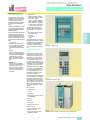
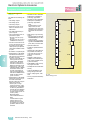
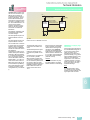
Fig. 2/2
SIMOREG 6RA70, 1 660 A Power module
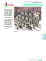
Fig. 2/3
SIMOREG 6RA70, 30 A converter, open door view
2/2
Siemens DC Drives Catalog · 2006
SIMOREG 6RA70 DC MASTER
Drive Description
6RA70
DC MASTER
Design and mode of operation
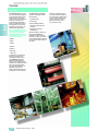
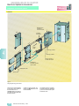
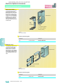
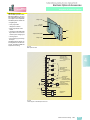
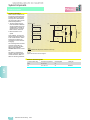
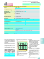
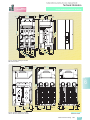
■ Parameterization devices
PMU simple operator panel
All units feature a PMU panel
mounted in the converter door.
The PMU consists of a five-digit, seven-segment display,
three LEDs as status indicators
and three parameterization
keys.
The PMU also features connector X300 with a USS interface in
compliance with the RS232 or
RS485 standard.
The panel provides all the facilities required during start-up
for making adjustments or settings and displaying measured
values. The following functions
are assigned to the three panel
keys:
• P (select) key
Switches over between parameter number and parameter value and vice versa,
acknowledges fault messages.
• UP key
Selects a higher parameter
number in parameter mode or
raises the set and displayed
parameter value in value
mode. Also selects a higher
index on indexed parameters.
• DOWN key
Selects a lower parameter
number in parameter mode or
reduces the set and displayed parameter value in
value mode. Also selects a
lower index on indexed parameters.
• LED functions
– Ready: Ready to operate,
lights up in “Wait for operation enable” state.
– Run: In operation, lights up
when operation is enabled.
– Fault: Disturbance, lights up
in “Active fault” status, flashes when “Alarm” is active.
The quantities output on the
five-digit, seven-segment display are easy to understand,
e.g.
– percentage of rated value,
– servo gain factor,
– seconds,
– amperes or
– volts.
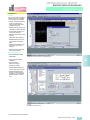
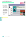
Through the X300 connector on
the PMU communication can be
established via the DriveMonitor
program for parameterization,
monitoring, troubleshooting,
and control of the converter by a
PC.
2
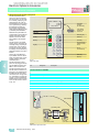
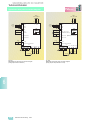
Fig. 2/4
PMU built in operator panel
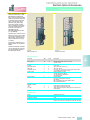
OP1S Extended operator
panel
The OP1S optional extended
operator panel can be mounted
either in the converter door or
externally, e.g. in the cubicle
door. For this purpose, it can be
connected up by means of a
5 m long cable. Cables of up to
200 m in length can be used if a
separate 5 V supply is available.
The OP1S is connected to the
SIMOREG via connector X300.
The OP1S can be installed as
an economic alternative to control cubicle measuring instruments which display physical
measured quantities.
The OP1S features an LCD with
4 x 16 characters for displaying
parameter names in plaintext.
German, English, French, Spanish and Italian can be selected
as the display languages. The
OP1S can store parameter sets
for easy downloading to other
devices.
Fig. 2/5
OP1S Extended operator panel
Keys on OP1S:
• P (Select) key
• UP key
• DOWN key
• Reversing key (not functional
on SIMOREG)
• ON key
• OFF key
• Inching key
• Numeric keys (0 to 9)
LEDs on OP1S:
• Green: Lights up in “Run”,
flashes in “Ready”
• Red: Lights up with “Fault”,
flashes with “Alarm”
Fig. 2/6
SIMOREG 6RA70 converter featuring optional OP1S operator panel
Siemens DC Drives Catalog · 2006
2/3
SIMOREG 6RA70 DC MASTER
Drive Description
6RA70
DC MASTER
Design and mode of operation
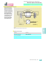
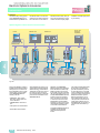
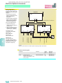
■ Software structure
Two powerful microprocessors
(C163 and C167) perform all
closed-loop and drive control
functions for the armature and
field circuit. Closed-loop control functions are implemented
in the software as program
modules that are “wired up” via
parameters.
Connectors
2
All important quantities in the
closed-loop control system can
be accessed via connectors.
They correspond to measuring
points and can be accessed as
digital values. 14 bits (16 384
steps) correspond to 100 % in
the standard normalization.
These values can be used for
other purposes in the converters, e.g. to control a setpoint or
change a limit. They can also
be output via the operator panel, analog outputs and serial interfaces.
The following quantities are
available via connectors:
• Analog inputs and outputs
• Inputs of actual-value sensing circuit
• Inputs and outputs of rampfunction generator, limitations, gating unit, controllers,
freely available software
modules
• Digital fixed setpoints
• General quantities such as
operating status, motor temperature, thyristor temperature, alarm memory, fault
memory, hours run meter,
processor capacity utilization
2/4
Binectors
Switchover of parameter sets
Switchover of BICO data sets
Binectors are digital control signals which can assume a value
of “0” or “1”. They are employed, for example, to inject a
setpoint or execute a control
function. Binectors can also be
output via the operator panel,
binary outputs or serial interfaces.
4 copies of parameters with
numbers ranging from P100 to
P599 as well as some others are
stored in the memory. Binectors
can be used to select the active
parameter set. This function allows, for example, up to four different motors to be operated
alternately or four different gear
changes to be implemented on
one converter. The setting values for the following functions
can be switched over:
The BICO data set can be
switched over by the control
word (binector input). It is possible to select which connector or
binector quantity must be applied at the intervention point.
The control structure or control
quantities can therefore be flexibly adapted.
The following states can be accessed via binectors:
• Status of binary inputs
• Fixed control bits
• Status of controllers, limitations, faults, ramp-function
generator, control words, status words
Intervention points
The inputs of software modules
are defined at intervention
points using the associated parameters. At the intervention
point for connector signals, the
connector number of the desired signal is entered in the relevant parameter so as to define
which signal must act as the input quantity. It is therefore possible to use both analog inputs
and signals from interfaces as
well as internal variables to
specify setpoints, additional
setpoints, limitations, etc.
The number of the binector to
act as the input quantity is entered at the intervention point for
binector signals. A control function can therefore be executed
or a control bit output by means
of either binary inputs, controls
bits of the serial interfaces or
control bits generated in the
closed-loop control.
Siemens DC Drives Catalog · 2006
• Definition of motor and pulse
encoder
• Optimization of closed-loop
control
• Current and torque limitation
• Conditioning of speed controller actual value
• Speed controller
• Closed-loop field current
control
• Closed-loop EMF control
• Ramp-function generator
• Speed limitation
• Monitors and limit values
• Digital setpoints
• Technology controller
• Motorized potentiometer
• Friction compensation
• Flywheel effect compensation
• Speed controller adaptation
Motorized potentiometer
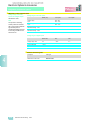
The motorized potentiometer
features control functions
“Raise”, “Lower”, “Clockwise/
Counterclockwise” and “Manual/Auto” and has its own rampfunction generator with mutually
independent ramp time settings
and a selectable rounding factor. The setting range (minimum
and maximum output quantities) can be set by means of parameters. Control functions are
specified via binectors.
In Automatic mode (“Auto” setting), the motorized potentiometer input is determined by a
freely selectable quantity (connector number). It is possible to
select whether the ramping
times are effective or whether
the input is switched directly
through to the output.
In the “Manual” setting, the setpoint is adjusted with the “Raise
setpoint” and “Lower setpoint”
functions. It is also possible to
define whether the output must
be set to zero or the last value
stored in the event of a power
failure. The output quantity is
freely available at a connector,
e.g. for use as a main setpoint,
additional setpoint or limitation.
SIMOREG 6RA70 DC MASTER
Drive Description
6RA70
DC MASTER
Design and mode of operation
■ Closed-loop functions in armature circuit
Speed setpoint
The source for the speed
setpoint and additional setpoints can be freely selected
through parameter settings, i.e.
the setpoint source can be programmed as:
• Analog values 0 to ±10 V,
0 to ±20 mA, 4 to 20 mA
• Integrated motorized potentiometer
• Binectors with functions:
Fixed setpoint, inch, crawl
• Serial interfaces on basic unit
• Supplementary boards
The normalization is such that
100 % setpoint (product of
main setpoint and additional
setpoints) corresponds to the
maximum motor speed.
The speed setpoint can be limited to a minimum or maximum
value by means of a parameter
setting or connector. Furthermore, “adding points” are included in the software to allow,
for example, additional setpoints to be injected before or
after the ramp-function generator. The “Setpoint enable” function can be selected with a
binector. After smoothing by a
parameterizable filter (PT1 element), the total setpoint is
transferred to the setpoint input
of the speed controller. The
ramp-function generator is effective at the same time.
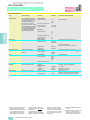
Actual speed value
One of four sources can be selected as the actual speed signal.
• Analog tachometer
The voltage of the tacho-generator at maximum speed can
be between 8 and 270 V. The
voltage/maximum speed normalization is set in a parameter.
• Pulse encoder
The type of pulse encoder, the
number of marks per revolution and the maximum speed
are set via parameters. The
evaluation electronics are capable of processing encoder
signals (symmetrical: With additional inverted track or
asymmetrical: Referred to
ground) up to a maximum differential voltage of 27 V.
The rated voltage range (5 V
or 15 V) for the encoder is set
in a parameter. With a rated
voltage of 15 V, the SIMOREG
converter can supply the voltage for the pulse encoder. 5 V
encoders require an external
supply. The pulse encoder is
evaluated on the basis of three
tracks, i.e. track 1, track 2 and
zero marker. Pulse encoders
without a zero marker may
also be installed. The zero
marker allows an actual position to be acquired. The maximum frequency of the
encoder signals must not exceed 300 kHz. Pulse encoders
with at least 1 024 pulses per
revolution are recommended
(to ensure smooth running at
low speeds).
• Operation without tachometer
and with closed-loop EMF
control
No actual-value sensor is
needed if the closed-loop EMF
control function is employed.
Instead, the converter output
voltage is measured in the
SIMOREG. The measured armature voltage is compensated by the internal voltage drop
in the motor (I*R compensation). The degree of compensation is automatically
determined during the current
controller optimization run.
The accuracy of this control
method is determined by the
temperature-dependent
change in resistance in the
motor armature circuit and
equals approximately 5 %. In
order to achieve greater accuracy, it is advisable to repeat
the current controller optimization run when the motor is
warm. Closed-loop EMF control can be employed if the accuracy requirements are not
particularly high, if there is no
possibility of installing an encoder and if the motor is operated in the armature voltage
control range.
Caution: The drive cannot be
operated in EMF-dependent
field- weakening mode when
this control method is employed.
• Freely selectable actual speed
signal
Any connector number can be
selected as the actual speed
signal for this operating mode.
This setting is selected in most
cases if the actual speed sensor is implemented on a technological supplementary
board.
Before the actual speed value
is transferred to the speed
controller, it can be smoothed
by means of a parameterizable smoothing (PT1 element)
and two adjustable band filters. The band filters are mostly used in order to filter out
resonant frequencies caused
by mechanical resonance.
The resonant frequency and
filter quality can be selected.
Ramp-function generator
The ramp-function generator
converts the specified setpoint
after a step change into a setpoint signal that changes constantly over time. Ramp-up and
ramp-down times can be set independently of one another.
The ramp-function generator
also features a lower and upper
transition rounding (jerk limitation) which take effect at the beginning and end of the ramp
time respectively.
All time settings for the rampfunction generator are mutually
independent.
3 parameter sets are provided
for the ramp-function generator
times. These can be selected
via binary selectable inputs or a
serial interface (via binectors).
The generator parameters can
be switched over while the drive
is in operation. The value of parameter set 1 can also be
weighted multiplicatively via a
connector (in order to change
generator data by means of a
connector). When ramp-function generator time settings of
zero are entered, the speed setpoint is applied directly to the
speed controller.
Speed controller
The speed controller compares
the speed setpoint and actual
value and, if these two quantities deviate, applies a corresponding current setpoint to the
current controller (operating
principle: Closed-loop speed
control with subordinate current
controller). The speed controller
is a PI controller with additional
selectable D component. A
switchable speed droop can
also be parameterized. All controller characteristics can be set
independently of one another.
The value of Kp (gain) can be
adapted as the function of a
connector signal (external or
internal).
Siemens DC Drives Catalog · 2006
2/5
2
SIMOREG 6RA70 DC MASTER
Drive Description
6RA70
DC MASTER
Design and mode of operation
■ Closed-loop functions in armature circuit
2
The P gain of the speed controller can be adapted as a
function of actual speed, actual
current, setpoint/actual value
deviation or winding diameter.
To achieve a better dynamic
response in the speed control
loop, a feedforward control
function can be applied by, for
example, adding a torque setpoint quantity after the speed
controller as a function of friction or drive moment of inertia.
The friction and moment of inertia compensation values can
be calculated in an automatic
optimization run.
The output quantity of the
speed controller directly after
enabling can be set via a parameter.
Depending on how parameters
are set, the speed controller
can be bypassed and the converter operated under torque
or current control. Furthermore,
it is possible to switch between
closed-loop speed control/
closed-loop torque control in
operation by means of selection function “Master/slave
switch-over”. The function can
be selected as a binector via a
binary assignable-function terminal or a serial interface. The
torque setpoint is applied by
means of a selectable connector and can thus be supplied
by an analog assignable-function terminal or a serial interface.
In “slave drive” operation (under torque or current control), a
limiting controller is active.
Here, the limiting controller can
intervene on the basis of an adjustable, parameterized speed
limit in order to prevent the
drive from accelerating too far.
In this case, the drive is limited
to an adjustable speed deviation.
2/6
Torque limitation
Depending on parameterization, the speed controller output
acts as either the torque setpoint or current setpoint. In
closed-loop torque control
mode, the speed controller output is weighted with machine
flux F and then transferred as a
current setpoint to the current
limitation. Torque-control mode
is mostly used in conjunction
with field weakening so that the
maximum motor torque can be
limited independently of speed.
The following functions are
available:
• Independent setting of positive and negative torque limits
via parameters.
• Switchover of torque limit via
binector as a function of a parameterizable changeover
speed.
• Free input of torque limit by
means of a connector, e.g. via
analog input or serial interface.
The lowest input quantity is always applied as the current
torque limit. Additional torque
setpoints can be added after
the torque limit.
Current limitation
The purpose of the current limitation set after the torque limit is
to protect the converter and motor. The lowest input quantity is
always applied as the current
limit.
The following current limit values can be set:
• Independent setting of positive and negative current limits
via parameters (setting of
maximum motor current).
• Free input of current limit via a
connector, e.g. from an analog input or serial interface.
Siemens DC Drives Catalog · 2006
• Separate setting of current
limit via parameters for shutdown and fast stop.
• Speed-dependent current limitation: Parameters can be set
to implement an automatically
triggered, speed-dependent
reduction in the current limitation at high speeds (commutation limit curve of motor).
• I2t monitoring of power section: The temperature of the
thyristors is calculated for all
current values. When the thyristor limit temperature is
reached, the converter current
is either reduced to rated DC
current or the converter shut
down with fault message, depending on how the appropriate response parameter is set.
This function is provided to
protect the thyristors.
Current controller
The current controller is a PI
controller with mutually independent P gain and reset time
settings. The P or I component
can also be deactivated (to obtain pure P controller or pure I
controller). The actual current is
acquired on the three-phase AC
side by means of current transformers and applied to the current controller after A/D
conversion via a burden and
rectifying circuit. The resolution
is 10 bits for converter rated
current. The current limiting output is applied as the current setpoint.
The current controller output
transfers the firing angle to the
gating unit, the feedforward
control function acts in parallel.
Feedforward control
The feedforward control function in the current control loop
improves the dynamic response
of the control, allowing rise
times of between 6 and 9 ms to
be achieved in the current control loop. The feedforward control operates as a function of the
current setpoint and motor EMF
and ensures that the necessary
firing angle is transferred
speedily to the gating unit, in
both intermittent and continuous DC operation or when the
torque direction is reversed.
Auto-reversing module
The auto-reversing module
(only on converters for fourquadrant drives) acts in conjunction with the current control
loop to define the logical sequence of all processes required to reverse the torque
direction. One torque direction
can be disabled by a parameter
setting if necessary.
Gating unit
The gating unit generates the
gate pulses for the power section thyristors in synchronism
with the line voltage. Synchronization is implemented independently of the rotating field and
electronics supply and is measured on the power section. The
gating pulse position timing is
determined by the output values
of the current controller and
feedforward control. The firing
angle setting limit can be set in
a parameter.
The gating unit is automatically
adjusted to the connected line
frequency within a frequency
range of 45 to 65 Hz.
SIMOREG 6RA70 DC MASTER
Drive Description
6RA70
DC MASTER
Design and mode of operation
■ Closed-loop functions in field circuit
EMF controller
Field-current controller
The EMF controller compares
the EMF (induced motor voltage) setpoint and actual value
and specifies the setpoint for
the field current controller, providing an EMF-dependent
closed-loop field-weakening
control. The EMF controller operates as a PI controller, the P
and I components can be set
independently of one another.
The controller can also be operated as a pure P or pure I
controller. A feedforward control operates in parallel to the
EMF controller. This applies
feedforward control as a function of speed to the field current
setpoint by means of an automatically recorded field characteristic (see optimization
runs). An adding point is located after the EMF controller, at
which additional field current
setpoints can be entered via a
connector, e.g. analog input or
serial interface. The limitation
for the field current setpoint is
then applied (maximum and
minimum setpoint limits can be
set independently of one another). The limitation is implemented via a parameter or
connector, in which case the
minimum is applied as the upper limit and the maximum for
the lower limit.
The current controller for the
field is a PI controller with independent settings for Kp and Tn.
It can also be operated as a
pure P or pure I controller. A
feedforward control operates in
parallel to the field current controller. This calculates and sets
the firing angle for the field circuit as a function of current setpoint and line voltage. The
feedforward control supports
the current controller and ensures a good dynamic response
in the field circuit.
Gating unit
The gating unit generates the
gate pulses for the power section thyristors in synchronism
with the line voltage in the field
circuit. Synchronization is measured on the power section and
is not therefore dependent on
the electronics supply. The gate
pulse position timing is determined by the output values of
the current controller and feedforward control. The firing angle
setting limit can be set in a parameter. The gating unit is automatically adjusted to the
connected line frequency within
a frequency range of 45 to
65 Hz.
■ Optimization run
■ Monitoring and diagnosis
6RA70 converters are supplied
with parameters set to the factory settings. Automatic optimization runs can be selected by
means of special key numbers
to support setting of the controllers.
The following controller functions can be set in an automatic
automatization run:
• Current controller optimization
run for setting current controllers and feedforward controls
(armature and field circuit).
• Speed controller optimization
run for setting characteristic
data for speed controller.
• Automatic recording of friction
and moment of inertia compensation for feedforward
control of speed controller.
• Automatic recording of field
characteristic for an EMF-dependent closed-loop fieldweakening control and automatic optimization of EMF
controller in field-weakening
operation.
Furthermore, all parameters set
automatically during optimization runs can be altered afterwards on the operator panel.
Display of operational data
The operating status of the converter is displayed via parameter r000. Approximately 50
parameters are provided for
displaying measured values. An
additional 300 signals from the
closed-loop control can be selected in the software (connectors) for output on the display
unit. Examples of displayable
measured values: Setpoints,
actual values, status of binary
inputs/outputs, line voltage, line
frequency, firing angle, inputs/
outputs of analog terminals, input/output of controllers, display of limitations.
Trace function
The trace function can be selected to store up to 10 measured quantities with 128 measuring points each. A measured
quantity or the activation of a
fault message can be parameterized as a trigger condition. It
is possible to record the preevent and post-event history by
programming a trigger delay.
The sampling time for the measured-value memory can be parameterized to between 3 and
300 ms.
Measured values can be output
via the operator panels or serial
interfaces.
Fault messages
A number is allocated to each
fault message. The time at
which the event occurred is also
stored with the fault message,
allowing the fault cause to be
pinpointed promptly. The most
recent 8 fault messages are
stored with fault number, fault
value and hours count for diagnostic purposes.
Fig. 2/7
SIMOREG converter family
Siemens DC Drives Catalog · 2006
2/7
2
SIMOREG 6RA70 DC MASTER
Drive Description
6RA70
DC MASTER
Design and mode of operation
■ Monitoring and diagnosis
When a fault occurs
• the binary output function
“Fault” is set to LOW (selectable function),
• the drive is switched off (controller disable and current
I = 0, pulse disable, relay
“Line contactor CLOSED”
drops out) and
• an F with a fault number appears on the display, LED
“Fault” lights up.
2
Fault messages can be acknowledged on the operator
panel, via a binary assignablefunction terminal or a serial interface. When the fault has
been acknowledged, the system switches to the “Starting
lockout” status. “Starting lockout” is cancelled by OFF (L signal at terminal 37).
Automatic restart: The system
can be restarted automatically
within a parameterizable time
period of 0 to 2 s. If this time is
set to zero, a fault message is
activated immediately (on power failure) without a restart.
Automatic restart can be parameterized in connection with
the following fault messages:
Phase failure (field or armature), undervoltage, overvoltage, failure of electronics power supply, undervoltage on
parallel SIMOREG unit.
■ Functions of inputs and
Fault/error messages are divided into the following categories:
• Line fault: Phase failure, fault
in field circuit, undervoltage,
overvoltage, line frequency
< 45 or > 65 Hz
• Interface fault: Basic unit interfaces or interfaces to supplementary boards are
malfunctioning.
Special states are indicated by
alarms. These states do not
lead to drive shutdown nor do
the alarms need to be acknowledged, but are automatically reset when the cause of the
problem has been eliminated.
When one or several alarms occur,
• Drive fault: Monitor for speed
controller, current controller,
EMF controller, field current
controller has responded,
drive blocked, no armature
current
• the binary output function
“Alarm” is set to LOW (selectable function) and
• Electronic motor overload protection (I2t monitor for motor)
has responded
Alarms are divided into the following categories:
• Tacho-generator monitor and
overspeed signal
• Start-up error
• Fault on electronics board
• Fault message from thyristor
check: This fault message will
occur only if the thyristor
check is activated via the appropriate parameter. The
check function ascertains
whether the thyristors are capable of blocking and firing.
• Fault messages from motor
sensors (with terminal expansion option); Monitor of brush
length, bearing condition, air
flow, motor temperature, has
responded
• External faults via binary assignable-function terminals
Fault messages can be deactivated individually. The default
setting for some fault messages
is “deactivated” so that they
need to be activated in the appropriate parameter.
2/8
Alarms
Siemens DC Drives Catalog · 2006
• the alarm is indicated by a
flashing “Fault” LED.
• Motor overtemperature: The
calculated I2t value of the motor has reached 100 %.
• Alarms from motor sensors
(only with terminal expansion
option): Monitor of bearing
condition, motor fan, motor
temperature, has responded.
• Drive alarms: Drive blocked,
no armature current.
• External alarms via binary assignable-function terminals.
• Alarms from supplementary
boards.
outputs
Analog selectable inputs
After conversion to a digital value, the quantity at the analog inputs can be flexibly adjusted in
terms of normalization, filtering,
sign selection and offset via parameters. Since these values
are available as connectors, the
analog inputs can also act as a
main setpoint or an additional
setpoint or limitation.
Analog outputs
The actual current is output as a
real-time quantity at terminal 12.
The output can be parameterized as a bipolar quantity or absolute value, with selectable
polarity.
Selectable analog outputs are
provided for the output of other
analog signals, in the form of a
bipolar signal or absolute value.
The normalization, offset, polarity and a filtering time can also
be parameterized. The required
output quantities are selected
by means of connector numbers specified at intervention
points. Possible outputs are, for
example, actual speed, rampfunction generator output, current setpoint, line voltage, etc.
SIMOREG 6RA70 DC MASTER
Drive Description
6RA70
DC MASTER
Design and mode of operation
■ Functions of inputs and outputs
Binary inputs
• Switch-on/Shutdown (OFF1) via
terminal 37
This terminal function is
ANDed with the control bit of
the serial interface. With an H
signal applied to terminal 37,
the main contactor (terminal
109/110) is energized via an
internal sequence control. If
an H signal is applied to terminal 38 (enable operation),
then the controllers are enabled. The drive accelerates
at the speed setpoint up to
operating speed. With an L
signal at terminal 37, the drive
is decelerated along the deceleration ramp down to
speed n < nmin. When the
brake control delay has expired, the controllers are disabled and the main contactor
de-energized when I = 0. The
field current is then reduced
to its standstill value (parameterizable) after a parameterizable delay following main
contactor dropout has expired.
• Enable operation via
terminal 38
This function is ANDed with
the control bit of the serial interface. The controllers are
enabled with an H signal applied to terminal 38. With an L
signal at terminal 38, the controllers are disabled and, at
I = 0, the pulses are disabled
too. The ”Enable operation”
signal has high priority, i.e. if
it changes to ”L” during operation, the effect is always
I = 0, causing the drive to
coast to a standstill.
Binary selectable inputs: Further binary input terminals are
provided for optional function
selections. A binector number is
assigned to each assignablefunction terminal for use for control functions.
Examples of binary input functions:
• Voltage disconnect (OFF2):
With an OFF2 (low) signal, the
controllers are disabled instantaneously, the armature
circuit current reduced and,
when I = 0, the main contactor
de-energized. The drive
coasts down in an uncontrolled manner.
• Fast stop (OFF3): With a fast
stop (low) signal, the speed
setpoint at the speed controller input is set to zero and the
drive braked along the current
limit (separate current limit
can be parameterized for fast
stop). When n < nmin, I = 0 is
input on expiry of the brake
control delay time and the
main contactor finally de-energized.
• INCH: The inching function is
available with an L signal at
terminal 37, an H signal at terminal 38 and activation of
inching mode. In active inching mode, the main contactor
is energized and the drive accelerated to a parameterized
inching setpoint. When the
inching signal is cancelled,
the drive is braked down to
n < nmin; the controllers are
then disabled and the main
contactor de-energized after a
parameterizable delay (0 to
60 s) has elapsed. It is also
possible to select whether the
ramp-function generator must
be active in inching mode or
whether a ramp-up time =
ramp-down time = 0 should be
applied.
Binary outputs
Selectable signalling functions
are available at binary output
terminals (open emitter output).
Any binector quantity - chosen
via the appropriate selection
parameter - can be output at
each terminal. The polarity of
the output signal and a settable
delay (0 to 15 s) can also be parameterized.
Examples of binary output functions:
• Fault: An L signal is output
when a fault message is
active.
• Alarm: An L signal is output
when an alarm is active.
• n < nmin: An H signal is output
at speeds of less than nmin.
This signal is used, for example, to active a zero-speed
message.
• Switch-on command for a mechanical brake: A motor brake
can be activated via this signal.
When the drive is switched on
with the “Drive ON” function and
“Enable operation” signal, an H
signal is output to release the
brake; output of the internal
controller enable signal is delayed for a parameterizable period (corresponding to
mechanical brake release time).
When the drive is stopped via
the “Shutdown” or “Fast stop”
function, an L signal to close the
brake is output when a speed of
n < nmin is reached. At the same
time, the internal controller enable signal remains active for a
parameterizable time period
(corresponding to mechanical
brake closing time). I = 0 is then
input, the pulses disabled and
the main contactor de-energized.
A further operating mode can
be selected for the “Close
brake” signal (L signal at binary
selectable output). With this option, there is no delay until
n < nmin is reached when “Internal controller disable” is applied
(drive is at zero current), but, instead, the (operating) brake is
activated at speeds greater
than nmin.
An internal controller disable
signal is output in response to
fault messages, voltage disconnection or cancellation of the
“Enable operation” signal at terminal 38 during operation.
Siemens DC Drives Catalog · 2006
2/9
2
SIMOREG 6RA70 DC MASTER
Drive Description
6RA70
DC MASTER
Design and mode of operation
■ Safety shutdown (E-STOP) ■ Serial interfaces
2
The task of the E-STOP function is to open the relay contacts (terminals 109/110) for
energizing the main contactor
within about 15 ms, independently of semiconductor components and the functional
status of the microprocessor
board (basic electronics). If the
basic electronics are operating
correctly, the closed-loop control outputs an I = 0 command
to de-energize the main contactor. When an E-STOP command is given, the drive coasts
to a standstill.
The E-STOP function can be
triggered by one of the following methods:
• Switch operation: E-STOP is
activated when the switch between terminals 105 and 106
opens.
The following serial interfaces
are available:
• One serial interface on connector X300 on the PMU for a
USS protocol to the RS232 or
RS485 standard. For connection of optional OP1S operator
panel or for PC-based
DriveMonitor.
• One serial interface at terminals of basic electronics
board, two-wire or four-wire
RS485 for USS protocol or
peer-to-peer connection.
• One serial interface at terminals of terminal expansion
board (option), two-wire or
four-wire RS485 for USS protocol or peer-to-peer connection.
• PROFIBUS DP on a supplementary card (optional).
• Pushbutton operation: Opening an NC contact between
terminals 106 and 107 triggers the E-STOP function and
stores the shutdown operation. Closing an NO contact
between terminals 106 and
108 resets the function.
• SIMOLINK on a supplementary card (optional) with fiberoptic connection.
When the E-STOP function is
reset, the drive switches to the
“Starting lockout” state. This
status needs to be acknowledged through activation of the
“Shutdown” function, e.g. by
opening terminal 37.
• CBD protocol
(Communication Board
DeviceNet) on a supplementary card (optional).
Note: The E-STOP function is
not an EMERGENCY STOP
function according to
EN 60 204-1.
• RS232: ±12 V interface for
point-to-point connection.
2/10
• CAN protocol
(Controller Area Network)
on a supplementary card
(optional).
Physical characteristics of
interfaces
• RS485: 5 V normal mode interface, noise-proof, for an additional bus connection with a
maximum of 31 bus nodes.
Siemens DC Drives Catalog · 2006
USS™ protocol
Peer-to-peer protocol
Disclosed SIEMENS protocol,
easy to program on external
systems, e.g. on PC, any master
interfaces can be used. The
drives operate as slaves on a
master. Drives are selected via
a slave number.
The peer-to-peer protocol is
used to link one converter to another. With this mode, data are
exchanged between converters, e.g. to build a setpoint cascade, via a serial interface.
Since a serial interface is employed as a four-wire line, it is
possible to receive data from
the upstream converter, condition them (e.g. through multiplicative weighting) and then send
them to the downstream converter. Only one serial interface
is used for the whole operation.
The following data can be exchanged via the USS protocol:
• PKW data for writing and reading parameters.
• PZD data (process data) such
as control words, setpoints,
status words, actual values.
Connector numbers are entered
in parameters to select the
transmit data (actual values),
the receive data (setpoints) represent connector numbers that
can be programmed to act at
any intervention points.
The following data can be exchanged between converters:
• Transmission of control words
and actual values.
• Reception of status words and
setpoints.
Up to five data words are transmitted in each direction. Data
are exchanged on the basis of
connector numbers and intervention points.
The serial interfaces can be operated simultaneously. For example, the first interface can be
used as an automation link (USS
protocol) for open-loop control,
diagnostics and specification of
the master setpoint. A second
interface operates in conjunction with the peer-to-peer protocol to act as a setpoint cascade.
SIMOREG 6RA70 DC MASTER
Drive Description
6RA70
DC MASTER
Power module block diagrams
6RA70..-6F and 6RA70..-4G
■ 6RA70..-6F, 15 A to 850 A
230 VAC
1 PH, 50/60Hz
2
230 VAC
460 VAC
3 PH, 50/60Hz 1 PH, 50/60Hz
460 VAC
1 PH, 50/60Hz
OR
230 VAC
SERIAL INTERFACE 2 RS485
ANALOG OUTPUTS
56 57 58 59 60
12 13 14 15 16 17
+
M
X172
M
BA
1
2
3
4
M
A
D
A
ES/
P24
E-STOP
M
D
5U1 5W1 5N1
XR
3U1 3W1
5U1 5W1 5N1
XP
1U1
4U1
1V1 1W1
CT1
CT2
FAN
1)
A
A
7
22
A
23
ON
255A - 850A
UNITS
OPEN AND CLOSED LOOP CONTROL
FOR ARMATURE AND FIELD
N10
6
4N1
XF1
XP
M
P10
5
24
M
110
XS
M
D
D
COMP COMP COMP
X>Y X>Y X>Y
P24
D
P15
MAIN
REFERENCE
10K
I act
109
105 106 107 108
X175
BA
NC
M
M
P24
M
M
36 37 38 39 46 47 48 49
M
X171
X173
26 27 28 29 30 31 32 33
XT
103
104
XF2
3C
3D
ENABLE
1D1
(1C1)
1C1
(1D1)
C
C
B
A
B
A
P15
4Q
COM
34 35
SWITCH ON
DC-5004b
M
SHUNT
FIELD
M
G
MOTOR
ANALOG
TACHOMETER
OR
PULSE ENCODER
1) Note:
Branch circuit fuses are internal on 850 A power module.
Fig. 2/8
Power module block diagram 15 A to 850 A
Siemens DC Drives Catalog · 2006
2/11
SIMOREG 6RA70 DC MASTER
Drive Description
Power module block diagrams
6RA70..-6F and 6RA70..-4G
6RA70
DC MASTER
■ 6RA70..-4G, 1 180 A and above
2
230 VAC
1 PH, 50/60Hz
460 VAC
575 VAC
3 PH, 50/60Hz 3 PH, 50/60Hz
460 VAC
1 PH, 50/60Hz
OR
230 VAC
SERIAL INTERFACE 2 RS485
ANALOG OUTPUTS
56 57 58 59 60
12 13 14 15 16 17
+
M
X172
M
BA
1
2
3
4
M
A
D
A
ES/
P24
E-STOP
M
D
5U1 5W1 5N1
XR
3U1 3W1
5U1 5W1 5N1
XP
1U1
4U1 4V1
1V1 1W1
CT1
CT2
FAN
OPEN AND CLOSED LOOP CONTROL
FOR ARMATURE AND FIELD
N10
A
A
7
22
A
23
2)
1)
P10
6
4W1
XF1
XP
M
5
24
M
110
XS
D
D
COMP COMP COMP
X>Y X>Y X>Y
P24
D
P15
MAIN
REFERENCE
10K
I act
109
105 106 107 108
X175
BA
NC
M
M
P24
M
M
36 37 38 39 46 47 48 49
M
X171
X173
26 27 28 29 30 31 32 33
XT
103
104
XF2
3C
3D
ENABLE
1D1
(1C1)
1C1
(1D1)
C
C
B
A
B
A
P15
M
COM
34 35
SWITCH ON
DC-5006b
M
SHUNT
FIELD
M
G
1) Note:
Branch circuit fuses are internal to power modules.
2) Note:
Fan must rotate counter-clockwise when viewed from above.
Fig. 2/9
Power module block diagram 1 180 A and above
2/12
Siemens DC Drives Catalog · 2006
MOTOR
ANALOG
TACHOMETER
OR
PULSE ENCODER
SIMOREG 6RA70 DC MASTER
Drive Description
6RA70
DC MASTER
Base drive block diagrams 6RA70..-2F
■ 6RA70..-2F, 15 A to 30 A
460 VAC
3 PH, 50/60Hz
84
83 82 85
L1
L2
L3
L1
2
L2
H1 H2 H3 H4
230 V
XF
X2
88
M
230 VAC
86
230 VAC
87
SERIAL INTERFACE 2 RS485
ANALOG OUTPUTS
56 57 58 59 60
12 13 14 15 16 17
+
M
X172
M
BA
1
2
3
4
M
M
A
D
A
D
5U1 5W1 5N1
XR
XS
ES/
P24
E-STOP
M
110
3U1 3W1
1U1
89
1V1 1W1
XF1
XP
CT1
CT2
M
P10
OPEN AND CLOSED LOOP CONTROL
FOR ARMATURE AND FIELD
N10
A
5
6
A
7
22
A
23
24
X175
I act
BA
109
105 106 107 108
230 VAC
D
D
COMP COMP COMP
X>Y X>Y X>Y
P24
D
P15
MAIN
REFERENCE
10K
M
M
P24
M
M
M
X171
X173
26 27 28 29 30 31 32 33
XT
103
104
XF2
3C
3D
1D1
(1C1)
1C1
(1D1)
C
C
B
A
B
A
P15
COM
ENABLE
36 37 38 39 46 47 48 49
SWITCH ON
34 35
M
4Q
M
DC-5000a
80
81
SHUNT
FIELD
A1
A2
M
G
90
91
MOTOR
ANALOG
TACHOMETER
OR
PULSE ENCODER
Fig. 2/10
Base drive panel block diagram 15 to 30 A
Siemens DC Drives Catalog · 2006
2/13
SIMOREG 6RA70 DC MASTER
Drive Description
6RA70
DC MASTER
Base drive block diagrams 6RA70..-2F
■ 6RA70..-2F, 60 A to 255 A
460 VAC
3 PH, 50/60Hz
84
83 82 85
L1
L2
L3
2
L1
L2
H1 H2 H3 H4
230 V
XF
X2
88
M
230 VAC
SERIAL INTERFACE 2 RS485
ANALOG OUTPUTS
56 57 58 59 60
12 13 14 15 16 17
+
M
X172
M
BA
1
2
3
4
D
A
D
XR
XS
ES/
P24
E-STOP
M
5U1 5W1 5N1
3U1 3W1
1U1
4U1
1V1 1W1
CT1
CT2
FAN
A
A
7
22
A
23
255A
ONLY
OPEN AND CLOSED LOOP CONTROL
FOR ARMATURE AND FIELD
N10
6
4N1
XF1
XP
M
P10
5
24
M
A
110
230 VAC
D
D
COMP COMP COMP
X>Y X>Y X>Y
P24
D
P15
MAIN
REFERENCE
10K
M
109
105 106 107 108
87
230 VAC
M
X175
I act
BA
86
230 VAC
M
P24
M
M
M
X171
X173
26 27 28 29 30 31 32 33
XT
103
104
XF2
3C
3D
1D1
(1C1)
1C1
(1D1)
C
C
B
A
B
A
P15
COM
ENABLE
36 37 38 39 46 47 48 49
SWITCH ON
34 35
M
4Q
M
80
DC-5001a
81
SHUNT
FIELD
A1
A2
M
G
Fig. 2/11
Base drive panel block diagram 60 A to 255 A
2/14
Siemens DC Drives Catalog · 2006
90
MOTOR
ANALOG
TACHOMETER
OR
PULSE ENCODER
91
89
SIMOREG 6RA70 DC MASTER
Drive Description
6RA70
DC MASTER
Base drive block diagrams 6RA70..-2F
■ 6RA70..-2F, 430 A to 510 A
460 VAC
3 PH, 50/60Hz
94
93
84
83 82 85
L1
L2
L3
EN
2
TO X171-38
L1
L2
H1 H2 H3 H4
230 V
XF
X2
88
SERIAL INTERFACE 2 RS485
ANALOG OUTPUTS
56 57 58 59 60
12 13 14 15 16 17
+
M
X172
M
BA
1
2
3
4
M
M
A
D
A
D
110
5U1 5W1 5N1
XR
XS
ES/
P24
E-STOP
M
3U1 3W1
1U1
4U1
1V1 1W1
A
A
7
22
A
23
230 VAC
89
4N1
XF1
XP
CT1
CT2
FAN
OPEN AND CLOSED LOOP CONTROL
FOR ARMATURE AND FIELD
N10
6
87
230 VAC
M
M
P10
5
24
X175
I act
BA
109
105 106 107 108
86
230 VAC
D
D
COMP COMP COMP
X>Y X>Y X>Y
P24
D
P15
MAIN
REFERENCE
10K
MREC
230 VAC
M
P24
M
X171
X173
26 27 28 29 30 31 32 33
XT
103
104
XF2
3C
3D
1D1
(1C1)
1C1
(1D1)
M
C
C
B
A
B
230 VAC
A
P15
M
36 37 38 39 46 47 48 49
SWITCH ON
34 35
M
COM
M
4Q
EN
EN
DC-5002a
80
81
SHUNT
FIELD
A1
A2
M
G
90
M AUX
91
MOTOR
ANALOG
TACHOMETER
OR
PULSE ENCODER
Fig. 2/12
Base drive panel block diagram 430 A to 510 A
Siemens DC Drives Catalog · 2006
2/15
SIMOREG 6RA70 DC MASTER
Drive Description
6RA70
DC MASTER
Base drive block diagrams 6RA70..-2F
■ 6RA70..-2F, 850 A
460 VAC
3 PH, 50/60Hz
94
93
84
83 82 85
L1
L2
L3
EN
2
TO X171-38
L1
L2
H1 H2 H3 H4
230 V
XF
X2
88
SERIAL INTERFACE 2 RS485
ANALOG OUTPUTS
56 57 58 59 60
12 13 14 15 16 17
+
M
X172
M
BA
1
2
3
4
M
M
A
D
A
D
110
5U1 5W1 5N1
XR
XS
ES/
P24
E-STOP
M
3U1 3W1
1U1
4U1
1V1 1W1
A
22
A
23
4N1
XF1
XP
CT1
CT2
FAN
A
7
230 VAC
1)
OPEN AND CLOSED LOOP CONTROL
FOR ARMATURE AND FIELD
N10
6
87
230 VAC
M
M
P10
5
24
X175
I act
BA
109
105 106 107 108
86
230 VAC
D
D
COMP COMP COMP
X>Y X>Y X>Y
P24
D
P15
MAIN
REFERENCE
10K
MREC
230 VAC
M
P24
M
X171
X173
XT
103
104
XF2
3C
3D
1D1
(1C1)
1C1
(1D1)
230 VAC
M
C
C
B
A
B
26 27 28 29 30 31 32 33
A
36 37 38 39 46 47 48 49
P15
M
SWITCH ON
34 35
M
COM
M
EN
EN
80
DC-5003a
81
SHUNT
FIELD
A1
A2
M
G
1) Note:
Branch circuit fuses are internal to power modules.
Fig. 2/13
Base drive panel block diagram 850 A
2/16
Siemens DC Drives Catalog · 2006
90
MOTOR
ANALOG
TACHOMETER
OR
PULSE ENCODER
M AUX
91
89
SIMOREG 6RA70 DC MASTER
Drive Description
6RA70
DC MASTER
Base drive block diagrams 6RA70..-2F
■ 6RA70..-2F, 1 180 A and 1 660 A and 1680 A
460 VAC
3 PH, 50/60Hz
94
93
L1
L2
L3
98
97
96
99
100
101
EN
2
TO X171-38
H1
L1
H4
H1
L2
H1 H2 H3 H4
H1 H2 H3 H4
ANALOG OUTPUTS
56 57 58 59 60
12 13 14 15 16 17
+
M
X172
M
BA
1
2
3
4
M
M
A
D
A
85
82
84
83
5U1 5W1 5N1
XR
3U1 3W1
1U1
4V1
1V1 1W1
A
A
22
A
23
L1
L2
L3
T1
T2
T3
4N1
XF1
XP
CT1
CT2
FAN
2)
OPEN AND CLOSED LOOP CONTROL
FOR ARMATURE AND FIELD
N10
7
X2
1)
P10
6
460 V
X1
X2
M
110
XS
ES/
P24
E-STOP
M
D
X2
M
5
24
I act
BA
109
105 106 107 108
X175
X1
D
D
COMP COMP COMP
X>Y X>Y X>Y
P24
D
P15
MAIN
REFERENCE
10K
MREC
XF
H1 H2 H3 H4
460 V
230 V
SERIAL INTERFACE 2 RS485
H4
M
P24
M
X171
X173
XT
103
104
XF2
3C
3D
1D1
(1C1)
1C1
(1D1)
230 VAC
M
C
C
B
A
B
26 27 28 29 30 31 32 33
A
36 37 38 39 46 47 48 49
P15
M
SWITCH ON
34 35
M
COM
M
EN
EN
DC-5005a
80
81
SHUNT
FIELD
A1
A2
M
G
90
M AUX
91
MOTOR
ANALOG
TACHOMETER
OR
PULSE ENCODER
1) Note:
Branch circuit fuses are internal to power modules.
2) Note:
Fan must rotate counter-clockwise when viewed from above.
Fig. 2/14
Base drive panel block diagram 1 180 A and 1 660 A, 1680 A
Siemens DC Drives Catalog · 2006
2/17
SIMOREG 6RA70 DC MASTER
Drive Description
6RA70
DC MASTER
Power and base drive modules
■ Terminal assignments
Type
Terminal design
Function
Power section
The converters are designed
for a permanent power supply
connection according to
DIN VDE 0160 Section 6.5.2.1.
Power module
PE conductor connection:
Minimum cross-section 10 mm2
The connection cross-sections
must be determined according
to the applicable regulations,
e.g. DIN VDE 100 Part 523,
DIN VDE 0276 Part 1 000.
2
Field circuit
Terminal
Connection values/comments
Armature line input
1U1
1V1
1W1
See technical data
Protective conductor PE
e
Armature circuit/
motor connection
1C1 (1D1)
1D1 (1C1)
Base drive
Incoming supply
L1
L2
L3
Protective conductor PE
e
Armature circuit/
motor connection
A1
A2
2-ph. AC 400 to 460 V (+15 %/–20 %)
Power module
Mains connection
XF1-2/3U1
XF1-1/3W1
300 V rated DC voltage
with 2-ph. AC 460 V mains connection
Field winding
connection
Electronics power
supply 1)
Type 49 plug-in terminal
Max. cross-section 1.5 mm2,
stranded
Fan 2)
Power module
XP/5U1
XP/5W1
XP/5N1
Incoming supply
Power module
Safety shutdown
(E-STOP)
Analog inputs,
tacho inputs
MSTB2.5 plug-in terminal
Max cross-section 2.5 mm2
MSTB2.5 plug-in terminal
Max. cross-section 2.5 mm2
1) Note: For converters with a power
section supply voltage that lies
outside the tolerance range (note
max. permissible power section
supply voltage), the electronics
power supply, field circuit mains
2/18
XF2-2/3C
XF2-1/3D
Further information
see technical data
Incoming supply
4UA1
(4N1)
4V1
4W
Protective conductor PE
e
Supply for safety
shutdown
XS/106
DC 24 V, max. load 50 mA, short-circuit-proof,
evaluation via fault message F028
Safety shutdown
– Switch
– Pushbutton
– Reset
XS/105 3)
XS/107 3)
XS/108 3)
Ie = 20 mA
NC contact Ie = 30 mA
NO contact Ie = 10 mA
Tacho connection
8 to 270 V
XT/103
Analog ground M
XT/104
connection and fan connection
must be adapted to AC 460 V via
a transformer.
An autotransformer is recommended for power section supply
voltages up to 500 V. An isolating
Siemens DC Drives Catalog · 2006
2-ph. AC 380 to 460 V (+15 %/–25 %); Irated = 1 A
1-ph. AC 190 to 230 V (+15 %/–25 %): Irated = 2 A
±270 V; >143 kΩ
Signs can be reversed and signals switched
through by means of binary input functions.
transformer must be used for
power section supply voltages
exceeding 500 V. This isolating
transformer must have a center
tap that is connected to protective earth PE.
2) On forced-ventilated converters
≥ 255 A.
3) Note: Either terminal 105 or terminals 107 + 108 may be used!
Terminal 105 is connected to terminal 106 in the delivery state.
SIMOREG 6RA70 DC MASTER
Drive Description
6RA70
DC MASTER
CUD1 Electronics board
■ CUD1 Block diagram
INPUTS
34
35
36
START
37
38
39
OUTPUTS
CUD 1
X171 BINARY INPUTS
+24 V DC SUPPLY 100 mA
COMMON
M
SERIAL INTERFACE #2 RS485 X172
SELECT INPUT BINARY 1
TX+ RS485
POWER ON / SHUTDOWN
TX- RS485
ENABLE OPERATION
RX+/TX+ RS485
SELECT INPUT BINARY 2
RS485
8.5 mA at 24 V
RX-/TX- RS485
M
X173 PULSE ENCODER INPUTS
GND
26
27
ENCODER
BA
A
A
B
B
ZERO MARKER
(OPTIONAL)
28
29
CW
59
60
BA
M
+
POSITIV E
BINARY OUTPUTS X171
NEGATIV E
SELECT OUTPUT 1
47
RELAY 2
48
OUTPUT TYPICAL
24 VDC, 100 mA MAX
NEGATIV E
RELAY 1
46
SELECT OUTPUT 2
CPU
32 POSITIV E
54
M
+24V DC
SPEED
POT
10K
58
M
30 POSITIV E
NEGATIV E
31
33
57
M
+15 V DC SUPPLY 200 mA
COMMON
56
X174 REFERENCE, ANALOG INPUTS, MOTOR TEMP
GND
1
COMMON
P10
3
N10
4
5
6
7
22
ANALOG OUTPUTS X175
M
2
(10V = 200% converter amps) Iact
RESOLUTION ADJUSTABLE
+/- 11 BITS TO +/- 14 BITS
A
MAIN SETPOINT +
MAIN SETPOINT -
D
150 K ohms
D
515 K ohms
MOTOR TEMP +
23 MOTOR TEMP 24
COMMON
M
X107
X110
X111
12
M
ANALOG 2
Analog Outputs:
RESOLUTION +/- 11 BITS
O to +/- 10 Volts, 2 mA MAX
V
15
16
M
V
13
14
M
A
ANALOG 1 +
ANALOG 1 -
ANALOG 1
V
17
OPERATOR
PANEL
X300
DC-5007b
OPTIONAL
COMMUNICATIONS AND
TECHNOLOGY BOARDS
OPTIONAL CUD2
TERMINAL EXPANSION
OPTIONAL
OP1S
OPERATOR
Fig. 2/15
CUD1 Block diagram with typical customer connections
Siemens DC Drives Catalog · 2006
2/19
2
SIMOREG 6RA70 DC MASTER
Drive Description
6RA70
DC MASTER
CUD1 Electronics board
■ Terminal assignments CUD1
Type
Terminal design
Function
Terminal
Connection values/comments
Analog inputs,
reference voltage
Plug-in (screw-type) terminal
Max. cross-section 1.5 mm2
Reference:
–M
– P10
– N10
X174/1
X174/2
X174/3
±1 % at 25 °C (stability 0.1 % per 10 °K);
10 mA short-circuit-proof
Selectable input:
– Main setpoint +
– Main setpoint –
X174/4
X174/5
Differential input
Parameter settings:
±10 V; 150 kΩ 1)
Resolution can be parameterized
up to approx. 555 µV (±14 bits)
0 to 20 mA; 300 Ω
4 to 20 mA; 300 Ω
Selectable input:
– Analog 1+
– Analog 1–
X174/6
X174/7
Differential input
Parameter settings:
±10 V; 150 kΩ 1)
Resolution can be parameterized
up to approx. 555 µV (±14 bits)
0 to 20 mA; 300 Ω
4 to 20 mA; 300 Ω
2
Signs can be reversed and signals switched
through by means of binary input functions.
Common mode suppression: ±15V
Pulse encoder input
Other analog inputs
Analog outputs
Plug-in (screw-type) terminal
Max. cross-section 1.5 mm2
Plug-in (screw-type) terminal
Max. cross-section 1.5 mm2
Plug-in (screw-type) terminal
Max. cross-section 1.5 mm
1) Resolution can be parameterized
up to approx. 555 µV (±14 bits)
2/20
Supply
(+13.7 V to +15.2 V)
X173/26
Pulse encoder ground M
X173/27
Track 1:
– Positive terminal
– Negative terminal
X173/28
X173/29
Load: ≤5.25 mA at 15 V
(w/o switching losses, see para. cable,
cable length, shield connection 2)
Track 2:
– Positive terminal
– Negative terminal
X173/30
X173/31
Switching hysteresis:
Pulse/pause ratio: 1:1
Zero marker:
– Positive terminal
– Negative terminal
X173/32
X173/33
Level of input pulses: 2)
Track offset: See Table 1/2 2)
Pulse frequency: See Table 1/3 2)
Cable length
Motor temperature:
– Positive terminal
– Negative terminal
X174/22
X174/23
Sensor acc. to P490, index 1
Sensor acc. to P490, index 1
PTC or KTY84-130
Analog ground M
X174/24
Actual current
Analog ground M
X175/12
X175/13
0 ± 10 V corresponds to 0 ± 200 %
Converter rated DC current
Max. load 2 mA, short-circuit-proof
Analog selectable output 1
Analog ground M
X175/14
X175/15
0 ± 10 V, max. 2 mA, short-circuit-proof
Resolution ±11 bits
Analog selectable output 2
Analog ground M
X175/16
X175/17
0 ± 10 V, max. 2 mA, short-circuit-proof
Resolution ±11 bits
2) See Section “Characteristic data of
pulse tacho evaluation electronics”
Siemens DC Drives Catalog · 2006
200 mA; short-circuit-proof
(electronic protection)
SIMOREG 6RA70 DC MASTER
Drive Description
6RA70
DC MASTER
CUD1 Electronics board
■ Terminal assignments CUD1
Type
Terminal design
Function
Terminal
Connection values/comments
Binary control inputs
Plug-in (screw-type) terminal
Max. cross-section 1.5 mm2
Supply
X171/34
24 V DC, max. load 100 mA,
internal supply referred to internal ground
Digital ground M
X171/35
Switch-on/shutdown
X171/37
• H signal: Switch-on 1)
Line contactor CLOSED + (with H signal
at terminal 38), acceleration along rampfunction generator ramp to operating speed.
• L signal: Shutdown 1)
Deceleration along ramp-function
generator ramp to n < nmin (P370) + controller
disable + line contactor OPEN.
Enable operation
X171/38
• H signal: Controller enabled 1)
• L signal: Controller disabled 1)
The L signal also acts at a higher level
on ”Inch” and ”Crawl”.
Binary control outputs
Plug-in (screw-type) terminal
Max. cross-section 1.5 mm2
Serial interface 1
RS232/X300 3)4)5)
Serial interface 2
RS485 7)8)
Plug-in (screw-type) terminal
Max. cross-section 1.5 mm2
Binary selectable input
X171/39
1
Binary selectable input
(fault acknowledgement)
X171/36
The group message is acknowledged on a
positive edge. The converter remains in the
“Fault” state until the fault has been eliminated
and acknowledged and then switches to the
“Starting lockout” state. The “Starting lockout”
state can be reset by applying an L signal
to terminal 37. 1)
Ground M:
– Binary selectable outputs
– Binary selectable outputs
X171/47
X171/54
Selectable output “Fault”
X171/46
• H signal: No fault 2)
• L signal: Fault 2)
Short-circuit-proof 100 mA 2)
Binary selectable output 2
X171/48
Short-circuit-proof 100 mA 2)
Relay for line contactor:
– Common potential
– NO contact
XR/109
XR/110
Load rating:
≤ AC 250 V, 4 A; cos Φ = 1
≤ AC 250 V, 2 A; cos Φ = 0,4
≤ DC 30 V, 2 A
Housing earth
X300/1 6)
Receive cable
RS232 standard (V.24)
X300/2 6)
Send and receive cable,
two-wire RS485, pos.
diff. input/output
X300/3 6)
BOOT, control signal
for software update
X300/4 6)9)
Ground
X300/5 6)
5 V voltage supply
for OP1S
X300/6 6)
Send cable RS232
standard (V.24)
X300/7 6)
Send and receive cable,
two-wire RS485,
pos. diff. input/output
X300/8 6)
Ground
X300/9 6)
TX+
X172/56
RS485, 4-wire send cable,
positive differential input
TX–
X172/57
RS485, 4-wire send cable,
negative differential input
RX+/TX+
X172/58
RS485, 4-wire receive cable, positive
differential input, 2-wire send/receive cable,
positive differential input
RX–/TX–
X172/59
RS485, 4-wire receive cable, negative
differential input, 2-wire send/receive cable,
negative differential input
M X172/60
1) H signal: +13 to +33 V*
L signal: –33 to +3 V
or terminal open*
*for binary control inputs 8.5 mA
at 24 V
2) H signal: +16 to +30 V
L signal: 0 to +2 V
3) 9-pin SUBMIN D socket
)
4) Cable length:
– Up to 15 m
acc. to EIA RS232-C standard
– Up to 30 m
Capacitive load max. 2.5 nF
(cable and receiver)
5) A serial connection to a PLC or
PC can be made using connector
X300 on the PMU, allowing the
Ground
converter to be controlled and
operated from a central control
center or room.
6) Connector pin
7) Cable length:
– For baud rate of 187.5 kBd:
600 m
– For baud rate of ≤ 93.75 kBd:
1 200 m
8) Please observe DIN 19 245,
Part 1: In particular, the potential
difference between the data
reference potentials M of all interfaces must not exceed
–7 V/+12 V. If this cannot be guaranteed, then equipotential bonding must be provided.
9) For SIMOREG 6RA70, no function.
Siemens DC Drives Catalog · 2006
2/21
2
SIMOREG 6RA70 DC MASTER
Drive Description
6RA70
DC MASTER
Notes
2
2/22
Siemens DC Drives Catalog · 2006
SIMOREG 6RA70
DC MASTER
Selection & Ordering Data
3/2
Flow diagram for selection process
3/5
3/5
Power module selection
Single quadrant, non-regenerative
Four quadrant, regenerative
3/7
3/7
Base drive panel selection
Single quadrant, non-regenerative
Four quadrant, regenerative
3/6
3/6
High HP design selection
Single quadrant, non-regenerative
Four quadrant, regenerative
Siemens DC Drives Catalog · 2006
3
3/1
SIMOREG 6RA70 DC MASTER
Selection & Ordering Data
Flow diagram for selection process
6RA70
DC MASTER
Mandatory
Information
Step 1
Determine if Base Drive Panel or Power Module will be required
A base drive panel includes the power module along with fuses, control transformer, and
contactor all mounted and prewired on a backplane for convenient panel installation with a
single 3-phase source connection.
See chapter 2 for details on all models.
Step 2
Verify Supply & Control voltage requirements
Base drive panels require only a single 3-phase power source to supply the armature, field,
control voltage, and fan. On a typical base drive panel application a 460 V AC 3-phase source
would control a DC motor with a 500 V DC armature and a 300 V DC field.
For details see chapter 2.
3
Step 3
Determine Current Rating
Specification charts in chapter 6 contain US current ratings and HP relation.
US current ratings offer a 150% overload for 60 seconds.
Step 4
Determine if application requires a 1 Quad or 4 Quad converter
4 Quad allows the converter to motor and regenerate power in both directions.
1 Quad converters will only allow armature current to flow in the motoring direction and usually
coast to decelerate. For a 1 Quad converter to change the direction of a DC motor a field
reversal circuit is needed. See field reversal kits in chapter 5.
Step 5
Select appropriate model number from selection tables
See selection tables in this chapter.
Step 6
Determine if CUD2 Terminal Expansion Board is needed
CUD2 includes additional analog and binary I/O along with a paralleling and serial interface.
The optional CUD2 board mounts directly onto the main CUD1 board.
See terminal expansion board description in chapter 4 for details and ordering information.
Step 7
Determine if Extended Technology Software option CUD1 is needed
This software option opens many extended technology functions and applications.
In addition to offering a technology regulator, numerous mathematical and Boolean logic
function blocks are offered to handle winding and other higher level applications.
See description in chapter 4 for details and ordering information.
3/2
Siemens DC Drives Catalog · 2006
SIMOREG 6RA70 DC MASTER
Selection & Ordering Data
6RA70
DC MASTER
Flow diagram for selection process
Mandatory
Information
Step 8
Determine if Line Reactors are required
Line reacters provide the recommended impedance between converter and incoming supply.
See chapter 5 for details and ordering information.
Step 9
Determine if additional system components are needed
Isolation transformers, field reversing kits, and dynamic braking offerings are available for
loose mounting.
See chapter 5 for details and ordering information.
3
Step 10
Determine if optional Alpa-Numeric Operator Panel (OP1S) is requested
The SIMOREG 6RA70 is completely autonomous and can be completely programmed from the
built-in operator panel. For ease of commissioning and an expanded alphanumeric display the
OP1S optional operator panel with storage capabilities can be easily attached to the SIMOREG
6RA70.
See chapter 4 for OP1S description and ordering information.
Step 11
Determine if Communication Board will be implemented
USS and peer to peer communications with RS485 and RS232 ports are standard and no
option boards are required for the SIMOREG 6RA70.
For PROFIBUS, SIMOLINK and many other communication options see chapter 4 for
description and ordering information.
Step 12
Determine if Technology Board or other option is needed for this application
The T400 technology board has standard application-specific software packages along with
the ability to add customized software to handle even the most challenging applications.
Expansion boards such as the EB1 and EB2 are also available to increase the functionality
of the SIMOREG 6RA70.
See chapter 4 for description and ordering information.
Step 13
If an Option Board in Step 11 or 12 is selected the following adapters apply
The LBA local bus adapter is required if any board other than the CUD1 or CUD2 is to be used
in the electronics box. The LBA is sold separately and easily fitted into the electronics box.
The ADB adapter board is necessary if any half-size option board such as the CBP2 or SLB
is to be inserted into the electronics box. The ADB is sold separately and easily fits into the
electronics box after the LBA has been installed.
See chapter 4 for further details and ordering information.
Step 14
Place your order with the assurance that you are getting the top performing DC Drive
in the Industry with exceptional worldwide support.
Drive enclosures and motor-drive packages are readily available from Siemens to complete our DC offerings.
Contact your local Siemens sales office for additional information.
Siemens DC Drives Catalog · 2006
3/3
SIMOREG 6RA70 DC MASTER
Selection & Ordering Data
6RA70
DC MASTER
Power module selection
■ Power modules
Power modules are available in
single and four quadrant designs from 15 A to 3000 A ratings. Through the use of the
paralleling interface on the
CUD2 option board designs of
up to six paralleled power modules are possible.
For international use power
modules of various voltage
ratings are available. Refer to
Appendix A for a complete list
of power modules with US and
international IEC current ratings. Consult factory for details
and pricing.
3
Fig. 3/1
Power modules 15 A through 3000 A
3/4
Siemens DC Drives Catalog · 2006
SIMOREG 6RA70 DC MASTER
Selection & Ordering Data
6RA70
DC MASTER
Power module selection
■ Selection and ordering data
Power module
Single quadrant, non-regenerative
Horsepower
240 V DC
3
HP
7.5 HP
Rated Armature
A
500 V DC
7.5 HP
Catalog No. 1)2)4)
Rated Field
A
15 A DC
5 A DC
6RA7018-6FS22-0Z+X01
15
HP
30 A DC
10 A DC
6RA7025-6FS22-0Z+X01
15
HP
30
HP
60 A DC
10 A DC
6RA7028-6FS22-0Z+X01
25
HP
60
HP
100 A DC
10 A DC
6RA7031-6FS22-0Z+X01
40
HP
75
HP
140 A DC
15 A DC
6RA7075-6FS22-0Z+X01
60
HP
125
HP
210 A DC
15 A DC
6RA7078-6FS22-0Z+X01
75
HP
150
HP
255 A DC
25 A DC
6RA7082-6FS22-0Z+X01
125
HP
250
HP
430 A DC
25 A DC
6RA7085-6FS22-0Z+X01
150
HP
300
HP
510 A DC
30 A DC
6RA7087-6FS22-0Z+X01
250
HP
500
HP
850 A DC
30 A DC
6RA7091-6FS22-0Z+X01
350
HP
700
HP
1 180 A DC
40 A DC
6RA7093-4GS22-0Z+X01
500
HP
1 000
HP
1 660 A DC
40 A DC
6RA7095-4GS22-0Z+X01
500
HP
1000
HP
1680 A DC
85 A DC
6RA7096-4GS22-0Z+X01
Rated Armature
A
Rated Field
A
Catalog No. 1)2)4)
Power module
Four quadrant, regenerative 3)
Horsepower
240 V DC
3
500 V DC
HP
7.5 HP
15 A DC
5 A DC
6RA7018-6FV62-0Z+X01
15
7.5 HP
HP
30 A DC
10 A DC
6RA7025-6FV62-0Z+X01
15
HP
30
HP
60 A DC
10 A DC
6RA7028-6FV62-0Z+X01
25
HP
60
HP
100 A DC
10 A DC
6RA7031-6FV62-0Z+X01
40
HP
75
HP
140 A DC
15 A DC
6RA7075-6FV62-0Z+X01
60
HP
125
HP
210 A DC
15 A DC
6RA7078-6FV62-0Z+X01
75
HP
150
HP
255 A DC
25 A DC
6RA7082-6FV62-0Z+X01
125
HP
250
HP
430 A DC
25 A DC
6RA7085-6FV62-0Z+X01
150
HP
300
HP
510 A DC
30 A DC
6RA7087-6FV62-0Z+X01
250
HP
500
HP
850 A DC
30 A DC
6RA7091-6FV62-0Z+X01
350
HP
700
HP
1 180 A DC
40 A DC
6RA7093-4GV62-0Z+X01
500
HP
1 000
HP
1 660 A DC
40 A DC
6RA7095-4GV62-0Z+X01
500
HP
1 000
HP
1 680 A DC
85 A DC
6RA7096-4GV62-0Z+X01
3) Designed for operation with
straight shunt wound motors.
4) Model numbers in this section
come equipped with the S00
extended technology function
enabled.
1)SIMOREG drive controllers will
be shipped without options
installed.
2)DC motor, drive enclosure,
contactor, most fuses, and
control transformer not included.
Siemens DC Drives Catalog · 2006
3/5
3
SIMOREG 6RA70 DC MASTER
Selection & Ordering Data
6RA70
DC MASTER
Base drive panel selection
■ Base drive panel models
Base drive panel models are
available in single and four
quadrant designs from 15 A to
1 660 A ratings. These models
feature the 6RA70 power
module, line fuses, contactor,
control transformer, and connections mounted on a back
panel.
Drive packages consisting of a
base drive controller and motor
along with drive enclosures are
also available. Consult factory
for details and pricing.
3
Fig. 3/2
Base drive panel examples of 15 A, 210 A and 510 A models
3/6
Siemens DC Drives Catalog · 2006
SIMOREG 6RA70 DC MASTER
Selection & Ordering Data
6RA70
DC MASTER
Base drive panel selection
■ Selection and ordering data
Base drive panel
Single quadrant, non-regenerative
Horsepower
240 V DC 1)
3
HP
7.5 HP
Rated Armature
A
500 V DC
7.5 HP
Catalog No. 2)3)
15 A DC
6RA7013-2FS22-0
15
HP
30 A DC
6RA7018-2FS22-0
15
HP
30
HP
60 A DC
6RA7025-2FS22-0
25
HP
60
HP
100 A DC
6RA7030-2FS22-0
40
HP
75
HP
140 A DC
6RA7072-2FS22-0
60
HP
125
HP
210 A DC
6RA7075-2FS22-0
75
HP
150
HP
255 A DC
6RA7077-2FS22-0
125
HP
250
HP
430 A DC
6RA7082-2FS22-0
150
HP
300
HP
510 A DC
6RA7083-2FS22-0
250
HP
500
HP
850 A DC
6RA7087-2FS22-0
350
HP
700
HP
1 180 A DC
6RA7091-2FS22-0
500
HP
1 000
HP
1 660 A DC
6RA7094-2FS22-0
3
Base drive panel
Four quadrant, regenerative 4)
Horsepower
240 V DC 1)
3
HP
7.5 HP
Rated Armature
A
500 V DC
7.5 HP
Catalog No. 2)3)
15 A DC
6RA7013-2FV62-0
15
HP
30 A DC
6RA7018-2FV62-0
15
HP
30
HP
60 A DC
6RA7025-2FV62-0
25
HP
60
HP
100 A DC
6RA7030-2FV62-0
40
HP
75
HP
140 A DC
6RA7072-2FV62-0
60
HP
125
HP
210 A DC
6RA7075-2FV62-0
75
HP
150
HP
255 A DC
6RA7077-2FV62-0
125
HP
250
HP
430 A DC
6RA7082-2FV62-0
150
HP
300
HP
510 A DC
6RA7083-2FV62-0
250
HP
500
HP
850 A DC
6RA7087-2FV62-0
350
HP
700
HP
1 180 A DC
6RA7091-2FV62-0
500
HP
1 000
HP
1 660 A DC
6RA7094-2FV62-0
1)Standard voltage configuration
as shipped is 460 V AC.
See Technical manual for
230 V AC connection.
2)SIMOREG drive controllers will
be shipped without options
installed.
3)DC motor and drive enclosure
not included.
4)Designed for operation with
straight shunt wound motors.
Siemens DC Drives Catalog · 2006
3/7
SIMOREG 6RA70 DC MASTER
Selection & Ordering Data
6RA70
DC MASTER
High HP designs selection
■ High HP designs
6RA70 high HP designs are
available in single and four
quadrant models with
continuous current ratings of
2 700 A, 5 000 A, and 7 500 A in
six pulse designs. High HP
designs with up to 14 000 A
ratings are also available in the
12-pulse design.
These converters have input
ratings up to 700 V AC and can
operate on DC motors with up
to a 750 V DC armature rating.
Typical short term overload ratings of 150 % for 60 s and
180 % for 30 s are common for
these units.
3
High HP 6RA70 designs are
mounted in robust Siemens
8MF enclosure systems and
can be ordered in various designs to meet the customers
needs. For additional information on the high HP 6RA70 designs contact your local
Siemens Sales Office.
Fig. 3/3
7 500 A four quadrant 6RA70 high HP design
Horsepower
ratings
Rated Armature
A
Catalog No.
Single quadrant, non-regenerative
Numerous design options are available, consult factory for details and selection.
Four quadrant, regenerative
Numerous design options are available, consult factory for details and selection.
3/8
Siemens DC Drives Catalog · 2006
SIMOREG 6RA70
DC MASTER
Electronic
Options & Accessories
4/2
Operator control and visualization
OP1S Operator panel
4/4
Technology software
4/5
CUD2 Terminal expansion board
4/8
4/9
4/10
4/10
4/11
4/13
4/15
4/17
4/21
Integration of electronic options
Overview
Mounting of optional supplementary boards
LBA Local bus adapter
ADB Adapter board
SBP Pulse encoder evaluation board
EB1 Expansion board
EB2 Expansion board
SCI1 and SCI2 Interface boards
T400 Technology board
4/26
4/27
4/29
4/31
4/33
4/34
Communications
Overview
SLB SIMOLINK board
CBP2 PROFIBUS-DP board
CAN Communication board CBC
CBD Communication board DeviceNet
SCB1 Interface board
4/35
4/35
4/35
4/35
4/35
Serial communications converters
DTU-3006
MD-3006
DN-3006
PD-3006
SCI-PU
4/36
4/39
4/40
Operating and monitoring
Drive ES engineering package
DriveMonitor
QuickStart
Siemens DC Drives Catalog · 2006
4/1
4
SIMOREG 6RA70 DC MASTER
Electronic Options & Accessories
6RA70
DC MASTER
Operator control and visualization
■ OP1S User-friendly operator control panel
The OP1S operator control
panel is an optional input/output device which can be used
for controlling, displaying, and
parameterizing the units. Parameterization is menu-guided
and is performed by selecting
the parameter number and
then entering the parameter
value. Plain-text displays greatly facilitate parameterization.
6.0%
*
LED green
The OP1S operator panel can
also be used as a remote-control device. The cable between
the PMU and the OP1S must
not exceed 50 m. If longer than
5 m, a standard 5 V power supply with a current capability of
at least 400 mA must be included on the OP1S end as shown
in Fig. 4/3.
Raise key
ON key
P
OFF key
Jog
DC-5009a
Jog key
Lower key
7
8
9
4
5
6
1
2
3
0
+/-
Reset
Key for toggling
between control
levels
0 to 9:
numerical keys
Reset key
Sign key
Fig. 4/1
View of the OP1S
Pin
Designation
Description
OP1S connections via RS485
1
2
3
RS485 p
Data via RS485 interface
4
5
N5V
Ground
6
P5V
5 V aux. voltage supply
7
8
PS485 N
Data via RS485 interface
9
Reference potential
6.0%
100.0V
00
25.00%
25.00%
Torque direc.1
#
*
Fault
Run
USS via RS485
P
Jog
7
8
4
5
9
6
1
2
3
0
+/-
Reset
Connecting cable
OP1S
9
8
7
6
5
4
3
2
1
OP1S side:
9-pin SUB D socket
Fig. 4/2
OP1S point-to-point connection
4/2
Siemens DC Drives Catalog · 2006
5
4
3
2
1
9
8
7
6
Unit side:
9-pin SUB D connector
DC-5010a
4
9-pin SUB D
connector on
rear of unit
Reversing key
The OP1S has a non-volatile
memory and is capable of permanently storing complete parameter sets. It can therefore
be used for archiving parameter settings and for transferring
parameter sets from one unit to
another.
The OP1S operator control
panel can be plugged directly
onto the SUB D socket of the
PMU on the converter door.
LC display
(4 lines x
16 characters)
Fault
Run
LED red
Parameter and parameter value descriptions, as well as text
displays in English, German,
Spanish, French and Italian,
are included in the standard
version.
On the rear of the OP1S is a
9-pin SUB D connector which
power is supplied and communication with the connected
units takes place.
100.0V
00
25.00%
25.00%
Torque direc.1
#
SIMOREG 6RA70 DC MASTER
Electronic Options & Accessories
6RA70
DC MASTER
Operator control and visualization
■ OP1S User-friendly operator control panel
The OP1S and the unit to be
operated communicate with
each other via a serial interface
(RS485) using the USS protocol (see Fig. 4/2). During communication, the OP1S assumes
the function of a master and the
connected units of slaves. The
OP1S can be operated at
transfer speeds of 9.6 kbit/s
and 19.2 kbit/s and is capable
of communicating with up to
31 slaves (address 1 to 31). It
can therefore be used in a
point-to-point link (operator
control of one unit) or with a
bus configuration (operator
control of several units).
Connecting cable
16.4 ft < I ≤ 656 ft (5 m < I ≤ 200 m)
9
8
7
6
5
5
4
4
3
3
2
2
1
1
9
8
7
6
> 400 mA
I–
DA65-5295
M
5 V DC
2
Vsupply
P5V
Vsupply
Unit side X300
9-pin SUB D socket
OP1S side
9-pin SUB D socket
Fig. 4/3
OP1S in a point-to-point link with up to 200 m of cable
4
■ Selection and ordering data
Description
Catalog No.
OP1S Operator control panel
6SE7090-0XX84-2FK0
AOP1 Door mounting adapter
(9.8 ft (3 m) cable included)
6SX7010-0AA00
Connecting cable PMU-OP1 9.8 ft (3 m)
6SE7010-0AB03
Connecting cable PMU-OP1 16.4 ft (5 m)
6SE7010-0AB05
Siemens DC Drives Catalog · 2006
4/3
SIMOREG 6RA70 DC MASTER
Electronic Options & Accessories
6RA70
DC MASTER
Technology software
Each SIMOREG 6RA70 contains an extended software
package that is released for
use by means of a PIN code.
This extended software package can be used to perform
many high level task and control schemes without the need
for a PLC or technology board.
Numerous applications including winders, extended control
logic, and draw/ratio speed
cascades can be implemented
using this software package.
The following is a list of the software modules and technology
controller functions included in
the extended technology software.
■ Software modules
• Two tracking/storage elements
• Three connector/binector converters
• Two analog signal memories
• Three binector/connector converters
• Two tracking/storage
elements
• One technology controller
• Ten analog signal selector
switches
• Ten PI controllers
• Nine characteristic blocks
• One simple ramp-function
generator
• One velocity/speed calculator
• Fifteen adders/subtracters
• Four sign inverters
• Two switchable sign inverters
• Six dividers
• Twelve multipliers
• Three high-resolution multipliers/dividers
• Four absolute-value generators with filter
• Three limit-value monitors with
filter
• Seven limit-value monitors
without filter
• Three limiters
4
■ Technology controller
The following software modules
are available:
• Four maximum selection with
three inputs
• One speed/velocity calculator
• 28 AND elements, each with
three inputs
• 20 OR elements, each with
three inputs
• 16 inverters
• Four EXCLUSIVE OR elements, each with two inputs
• Twelve NAND elements, each
with three inputs
• 14 RS flipflops
• Four D flipflops
• Ten timers
The technology controller can
be used for higher-level closedloop controls, such as tension,
position or pressure controllers.
The output can be wired freely
and can act, for example, as a
main setpoint, additional setpoint or current limit.
The technology controller is a
PID controller with separate settings for the closed-loop control
characteristics. A droop setting
is also available.
Connector numbers can be entered freely to select the source
for setpoint and actual value. A
filter (PT1 element) can be parameterized at the setpoint and
actual value inputs.
The technology controller output can be limited by mutually
independent, positive and negative values, which can be parameterized or input via freely
selectable connectors. The output signal can be weighted multiplicatively (parameterized or
via connector signal) after the
limiting stage.
• Five binary signal selector
switches
• One dead zone
• Eight alarm triggers
• Four minimum selection with
three inputs
• Thirty-two fault triggers
• Four averaging blocks
• Three multipliers
• Three integrators
• Three DTI elements
• Ten derivative/delay elements
(lead/lag blocks)
■ Selection and ordering data
Description
Catalog No.
Extended technology software S00 1)
6RX1700-0AS00
* The 6RA70 converters listed in chapter 3 are shipped from the factory
with the S00 option enabled.
1) When ordering this option you must supply the
model number and serial number of the unit
you wish to enable the extended software
function on. Each unit contains 500 free hours
of use.
4/4
Siemens DC Drives Catalog · 2006
SIMOREG 6RA70 DC MASTER
Electronic Options & Accessories
6RA70
DC MASTER
CUD2 Terminal expansion board
The optional terminal expansion board (CUD2) is mounted
on the basic electronics assembly (CUD1) and does not
require any additional built-in
components. This board provides a range of additional inputs and outputs.
In addition to the expanded I/O
the CUD2 provides an additional RS485 serial interface
along with a parallel interface
for paralleling up to 5 power
modules.
Terminals on optional
terminal expansion board
• 4 binary selectable inputs via
optocouplers, can also be
used as interface to motor
• 4 binary selectable inputs to
ground
• 2 analog inputs to ground,
±10-bit resolution
Fig. 4/4
CUD2 Terminal expansion board
• One analog input for evaluation of motor temperature via
PTC or KTY84
• 2 P24 binary outputs, open
emitter, to ground, 100 mA
load rating
4
• 2 analog outputs to ground,
±10 V, 2 mA load rating,
±11-bit resolution
• One serial interface,
two- and four-wire RS485,
max. 187.5 kBd
• One parallel interface (2 connectors) for parallel connection of SIMOREG
• P24 power supply for driving
binary inputs
• 8 terminals for converter
ground
Fig. 4/5
CUD2 shown mounted on the CUD1 basic electronic board
■ Selection and ordering data
Description
Catalog No.
CUD2 Terminal expansion board
6RX1700-0AK00
Siemens DC Drives Catalog · 2006
4/5
SIMOREG 6RA70 DC MASTER
Electronic Options & Accessories
CUD2 Terminal expansion board
■ Terminal assignments · Optional CUD2 control connections
4
Fig. 4/6
CUD2 Terminal expansion board block diagram
4/6
Siemens DC Drives Catalog · 2006
6RA70
DC MASTER
SIMOREG 6RA70 DC MASTER
Electronic Options & Accessories
6RA70
DC MASTER
CUD2 Terminal expansion board
■ Terminal assignments · Optional CUD2 control connections
Type
Terminal design
Function
Terminal
Connection values/comments
Motor interface
Plug-in (screw-type) terminal
Max. cross-section 1.5 mm2
Motor temperature:
– Positive terminal
– Negative terminal
X164/204
X164/205
Sensor acc. to P490, index 2
Sensor acc. to P490, index 2
Supply of binary inputs
X161/210
DC 24 V, max. load
Internal supply referred to internal ground,
effective when ground M_GT is connected to
internal ground (wire jumper closed between
terminals 216 and 217)
Binary input
X161/211
Binary input
X161/212
Binary input
X161/213
Binary input
X161/214
Ground M_GT:
– Binary inputs
– Binary inputs
X161/215
X161/216
Can be separated from internal ground
Wire jumper between terminals 216 and 217
open
M
X161/217
Wire jumper between terminals 216 and 217
open
Analog selectable input 2
X164/8
Analog ground
X164/9
Analog selectable input 3
X164/10
Analog ground
X164/11
±10 V, 52 kΩ
Resolution: ±10 bits
Signs can be reversed and signals switched
through by means of binary input functions
Analog selectable output 3
X164/18
Analog ground
X164/19
Analog selectable output 4
X164/20
Analog ground M
X164/21
Supply
X163/44
DC 24 V, max. load 100 mA,
internal supply referred to internal ground
Digital ground M
X163/45
1
Selectable input:
– Binary 3
– Binary 4
– Binary 5
– Binary 6
X163/40
X163/41
X163/42
X163/43
1
)
1
)
1
)
1
Ground M:
– Binary selectable outputs
– Binary selectable outputs
X163/51
X163/53
Selectable output:
– Binary 3
– Binary 4
X163/50
X163/52
2)
TX+
X162/61
RS485, 4-wire send cable,
positive differential input
TX–
X162/62
RS485, 4-wire send cable,
negative differential input
RX+/TX+
X162/63
RS485, 4-wire receive cable,
positive differential input, 2-wire send/receive
cable, positive differential input
RX–/TX–
X162/64
RS485, 4-wire receive cable,
negative differential input, 2-wire send/receive
cable, negative differential input
Analog inputs
Analog outputs
Binary control inputs
Binary control outputs
Serial interface 3
RS485 3)4)
Plug-in (screw-type) terminal
Max. cross-section 1.5 mm2
Plug-in (screw-type) terminal
Max. cross-section 1.5 mm2
Plug-in (screw-type) terminal
Max. cross-section 1.5 mm2
Plug-in (screw-type) terminal
Max. cross-section 1.5 mm2
Plug-in (screw-type) terminal
Max. cross-section 1.5 mm2
M X172/65
1) H signal: +13 to +33 V*
L signal: –33 to +3 V
or terminal open*
* for binary control inputs 8.5 mA at 24 V
2) H signal: +13 to +30 V
L signal: 0 to +2 V
3) Cable length:
– For baud rate of 187.5 kBd: 1 967 ft (600 m)
– For baud rate of ≤ 93.75 kBd: 3 938 ft
(1 200 m)
Motor data evaluation or data evaluation
0 ± 10 V, max. 2 mA,
short-circuit-proof, measuring ±11 bit
4
)
)
short-circuit-proof 100 mA
Ground
4) Please observe DIN 19 245, Part 1:
In particular, the potential difference between
the data reference potentials M of all interfaces
must not exceed –7 V/+12 V. If this cannot be
guaranteed, then equipotential bonding must
be provided.
Siemens DC Drives Catalog · 2006
4/7
SIMOREG 6RA70 DC MASTER
Electronic Options & Accessories
6RA70
DC MASTER
Integration of electronic options
■ Overview
Electronics box
mounted on
inner side of door
T400
DC-5011a
Local bus
LBA adapter
6RA70
tF
Slo
Option
board
4
Mounting position 2
D
lot
S
Mounting position 3
ot
Sl
G
Mounting position 1
for CUD1 and CUD2
ADB adapter
board with mounted
option boards
tE
Slo ADB adapter board
Option board
Fig. 4/7
Integrating/Mounting option boards
There are four slots available
for mounting option boards in
the electronics box of
SIMOREG 6RA70 converters.
The slots are designated with
the letters D to G.
4/8
If slots D to G are needed, the
LBA (Local Bus Adapter) must
first be installed.
Siemens DC Drives Catalog · 2006
An adapter board is necessary
for slots D and E and additionally for F and G if half size option
boards are used.
SIMOREG 6RA70 DC MASTER
Electronic Options & Accessories
6RA70
DC MASTER
Integration of electronic options
■ Mounting of optional supplementary boards
Supplementary option boards
are inserted in the slots of the
electronics box. Option LBA
(local bus adapter, backplane
wiring) is required to fit supplementary option boards. The
designations of board locations and slots are shown in the
following diagram.
1
2
F
D
G
E
CUDX
Supplementary option boards
may be inserted in any slots
subject to one restriction, i.e.
that board location 2 is filled
before location 3.
3
Note
• If a technology board is used
in conjunction with a communication board, then the
communication board must
be fitted in slot G. In this configuration the communication
data flows directly between
the communication board
and the T400.
DC-5015
• A technology board must always be installed in board location 2 of the electronics
box.
Fig. 4/8
Arrangement of board locations 1 to 3 and slots D to G in electronics box
Electronics box possible position assignments
Board
LBA
required
ADB
required
Location1
Location 2
D
E
Location 3
F
G
CUD1
N
N
Y
N
N
N
CUD2
N
N
Y
N
N
N
N
• The data of large-format
boards are always output under slot E or slot G, i.e. the
software version of a technology board, for example, is
displayed in r060.003.
CBP2
Y
Y
N
Y
Y
Y
Y
CBC
Y
Y
N
Y
Y
Y
Y
CBD
Y
Y
N
Y
Y
Y
Y
SLB
Y
Y
N
Y
Y
Y
Y
SBP
Y
Y
N
Y
Y
Y
Y
• In addition to the LBA, miniature-format boards (CBP2,
SLB, EB1, etc.) also require
an ADB (adapter board, support board). Due to their very
compact physical dimensions, these boards must be
inserted in an ADB before
they can be installed in the
electronics box.
SCB1
Y
N
N
Y
Y
T400
Y
N
N
Y
N
EB1
Y
Y
N
Y
Y
Y
Y
EB2
Y
Y
N
Y
Y
Y
Y
• It is not possible to operate
boards EB1, EB2, SLB and
SBP in conjunction with a
technology board.
4
N
• No more than 2 supplementary boards of the same type
may be installed in one converter (e.g. 2 EB1s).
Siemens DC Drives Catalog · 2006
4/9
SIMOREG 6RA70 DC MASTER
Electronic Options & Accessories
6RA70
DC MASTER
Integration of electronic options
■ LBA Local bus adapter
The electronics box can easily
be retrofitted with the backplane bus adapter LBA (Local
Bus Adapter), for use of positions 2 and 3. Full size option
boards or the optional boards
plugged onto the ADB (Adapter Board) can be combined in
the electronics box with the
CUD1 control board in slot 1.
The CUD1 must be removed to
install the LBA.
DC-5012
DC-5012
Electronics box
LBA
Local
bus adapter
Location 2 (Option)
Location 3 (Option)
Location 1 (CUD1)
Fig. 4/9
LBA Local bus adapter
■ Selection and ordering data
Description
4
LBA
Catalog No.
Local bus adapter
6SE7090-0XX84-4HA0
■ ADB Adapter board
The ADB (Adapter Board) is for
connecting half size option
boards such as the CBP2 or
SLB into slots 2 or 3 of the
electronics box. Two half size
option boards can be installed
on one ADB. Installation of an
LBA is required for use of the
ADB.
DC-5014
Electronics box
Backplane
adapter
Slot E
Adapter board ADB
Optional boards
Fig. 4/10
ADB Adapter board
■ Selection and ordering data
Description
ADB
4/10
Siemens DC Drives Catalog · 2006
Catalog No.
Adapter board
6SX7010-0KA00
SIMOREG 6RA70 DC MASTER
Electronic Options & Accessories
6RA70
DC MASTER
Integration of electronic options
■ SBP Pulse encoder evaluation board
The SBP (Sensor Board Pulse)
optional board allows a second
pulse encoder to be connected
to the SIMOREG converter.
Suitable pulse encoders
DA65-5105a
All commercially available
pulse encoders can be connected to this optional board.
Their pulses can be processed
as either bipolar or unipolar,
TTL- or HTL-level signals.
Encoder signals up to a pulse
frequency of 410 kHz (4 096
pulses per rev. at 6 000 rev/
min) can be evaluated. Encoder monitoring can also be implemented through evaluation
of the check track.
60
61
62
63
64
65
66
67
68
69
70
71
72
73
74
75
The supply voltage for the connected encoder can be set to
5 V or 15 V.
Temperature sensor
The temperature sensor connection on the board is not
evaluated in the SIMOREG system.
Connections
Fig. 4/11
SBP Pulse encoder evaluation board
Terminal assignments on terminal strip X400
Signal cables are connected to
terminal strips X400 and X401.
Terminal
Designation
Meaning
Range
Connectable cross-section:
2.5 mm2 (AWG12)
60
+VSS
Power supply for pulse encoder
5/15 V
Imax = 250 mA
61
–VSS
Power supply ground
62
–Temp
Negative (–)
terminal KTY84/PTC100
63
+Temp
Positive (+)
terminal KTY84/PTC100
64
Coarse/fine ground
Ground
65
Coarse pulse 1
Digital input for coarse pulse 1
66
Coarse pulse 2
Digital input for coarse pulse 2
67
Fine pulse 2
Digital input for fine pulse
4
3 mA
Accuracy ±1 %
Terminal assignments on terminal strip X401
Terminal
Designation
Meaning
Range
68
Track A+
Positive (+) terminal
Track A
TTL/HTL/HTL unipolar
69
Track A–
Negative (–) terminal
Track A
TTL/HTL/HTL unipolar
70
Track B+
Positive (+) terminal
Track B
TTL/HTL/HTL unipolar
71
Track B–
Negative (–) terminal
Track B
TTL/HTL/HTL unipolar
72
Zero pulse+
Positive (+) terminal
Zero track
TTL/HTL/HTL unipolar
73
Zero pulse–
Negative (–) terminal
Zero track
TTL/HTL/HTL unipolar
74
CTRL+
Positive (+) terminal
Check track
TTL/HTL/HTL unipolar
75
CTRL–
Negative (–) terminal
Check track
TTL/HTL/HTL unipolar
Siemens DC Drives Catalog · 2006
4/11
SIMOREG 6RA70 DC MASTER
Electronic Options & Accessories
6RA70
DC MASTER
Integration of electronic options
■ SBP Pulse encoder evaluation board
Voltage range of encoder
inputs and of digital inputs
Voltage range of encoder inputs
RS422 (TTI)
See tables for data.
Note
The inputs are not floating.
Coarse pulses are smoothed
with 0.7 ms and fine pulses with
approximately 200 ns.
The LBA and ADB are required
for mounting the SBP into the
electronics box.
HTL bipolar
Voltage range –
Input
Max. 33 V
Min. –33 V
Voltage range +
Input
Max. 33 V
Min. –33 V
HTL unipolar
Switching level
Differential voltage – LOW
Min. –150 mV
Min. –2 V
Min. 4 V
Switching level
Differential voltage – HIGH
Max. 150 mA
Max. 2 V
Max. 8 V
Rated value
Min.
Max.
Voltage range LOW
0V
–0.6 V
3V
Voltage range HIGH
13 V
24 V
33 V
Input current LOW
≤ 2 mA
Input current HIGH
10 mA
8 mA
12 mA
Voltage range of digital inputs
■ Selection and ordering data
4
4/12
Description
Catalog No.
SBP Pulse encoder board
6SX7010-0FA00
Siemens DC Drives Catalog · 2006
SIMOREG 6RA70 DC MASTER
Electronic Options & Accessories
6RA70
DC MASTER
Integration of electronic options
■ EB1 Expansion board
With the EB1 (Expansion
Board 1), it is possible to expand the number of digital and
analog inputs and outputs.
Fixing screw
The EB1 expansion board has
the following:
• 4 bidirectional digital inputs/
outputs
• 1 analog input with differential
signal which can be used as
a current/voltage input
• 2 analog inputs (single-ended) which can also be used
as digital inputs
64-pole
system connector
DA65-5169
• 3 digital inputs
X4
88
1
X4
87
1
Jumpers X486,
X487, X488
X4
86
1
Fixing screw
• 2 analog outputs
38
39
40
41
42
43
44
45
46
X480
47
48
49
50
51
52
53
54
X481
• 1 input for the external 24 V
power supply for the digital
outputs
Fig. 4/12
EB1 expansion board
24 V ext.
-
38
X480
+
43
44
4 bidirectional digital
inputs/outputs
24 V/4 kΩ (input)
24 V/100 mA (output)
Out/In
5V
45
24 V
46
Out
4
24 V supply (external)
The supply must be
dimensioned for the
output currents of the
digital outputs.
39
4 bidirectional digital inputs/outputs
40
24 V
41
42
3 digital inputs
24 V/4 kΩ
TTL
In
X481
47
A
48
A
D
2 analog outputs
11 bits + sign
±10 V/5 mA
D
49
50
+10
V
-
+20
mA
-
1
2
+
51
52
53
54
1 analog input
(differential)
13 bits + sign
±10 V/40 kΩ (voltage)
±20 mA/250 Ω (current)
X488
A
A
-
A
D
3
1
D
3
1
D
X486
2
2
X487
2 analog inputs
(single-ended)
13 bits + sign
±10 V/40 kΩ
Also useable as
digital inputs
Switching threshold 8 V
DA65-5427
The EB1 expansion board can
be integrated into the electronics box. The LBA and ADB are
required for mounting.
Fig. 4/13
Circuit diagram of the EB1 expansion board
Siemens DC Drives Catalog · 2006
4/13
SIMOREG 6RA70 DC MASTER
Electronic Options & Accessories
6RA70
DC MASTER
Integration of electronic options
■ EB1 Expansion board
Connection X480
Technical data
The following connections are
provided on the terminal strip:
• 3 digital inputs
• 4 bidirectional inputs/outputs
The ground cables are protected by a reactor. Terminal 46 is
at the top, when fitted.
Note:
An external 24 V supply is necessary and must be dimensioned for the currents of the
digital outputs.
Terminal
Designation
Description
Range
38
M
Ground digital
0V
39
P24 ext.
Ext. 24 V supply
20 V to 33 V
40
DI1
Digital input 1
24 V, Ri = 4 kΩ
41
DI2
Digital input 2
24 V, Ri = 4 kΩ
42
DI3
Digital input 3
24 V, Ri = 4 kΩ
43
DIO1
Digital input/output 1
44
DIO2
Digital input/output 2
45
DIO3
Digital input/output 3
46
DIO4
Digital input/output 4
As input:
24 V, 4 kΩ
As output:
Output voltage
P24 ext. 100 mA
Max. connectable cross-section: 1.5 mm2 (AWG 16)
Connection X481
4
The following connections are
provided on the terminal strip:
• 1 differential analog input with
signal, which can be used as
a current and voltage input
The ground cables are protected by a coil/inductor. Terminal
47 is at the top, when fitted.
Designation
Value
Digital inputs
DI1, DI2, DI3
• Voltage range LOW
• Voltage range HIGH
• Input resistance
• Smoothing
• Electrical isolation
0 V (–33 V to +5 V)
+24 V (13 V to 33 V)
4 kΩ
250 µs
None
Bidirectional digital inputs/outputs
DIO1, DIO2, DIO3, DIO4
As input
• Voltage range LOW
• Voltage range HIGH
• Input resistance
As output
• Voltage range LOW
• Voltage range HIGH
Analog input (differential input)
• Input range
Voltage
Current
• Input resistance
Voltage
Current
• Hardware smoothing
• Resolution
0 V (–33 V to +5 V)
+24 V (13 V to 33 V)
4 kΩ
<2 V
>P24 ext. –2.5 V
AI1P, AI1N
±11 V
±20 mA
40 kΩ to ground
250 Ω to ground
220 µs
13 bits + sign
Analog input (single-ended)
AI2, AI3, AIM
• Input range
• Input resistance
• Hardware smoothing
• Resolution
±11 V
40 kΩ to ground
220 µs
13 bits + sign
Analog output
AO1, AO2, AOM
• Voltage range
• Input resistance
• Hardware smoothing
• Resolution
±10 V
40 kΩ to ground
10 µs
11 bits + sign
• 2 analog inputs (single-ended) which can also be used
as digital inputs
• 2 analog inputs
■ Selection and ordering data
Terminal
Designation
Description
Range
Description
Catalog No.
47
AO1
Analog output 1
±10 V, 5 mA
EB1 Expansion board 1
6SX7010-0KB00
48
AO2
Analog output 2
±10 V, 5 mA
49
AOM
Ground analog output
0V
50
AI1P
Analog input 1 +
Voltage: ±10 V, 40 kΩ
51
AI1N
Analog input –
Current: ±20 mA, 250 Ω
52
AI2
Analog input 2
±10 V, 40 kΩ
53
AI3
Analog input 3
±10 V, 40 kΩ
54
AIM
Ground analog input
0V
Max. connectable cross-section: 1.5 mm2 (AWG 16)
4/14
Siemens DC Drives Catalog · 2006
SIMOREG 6RA70 DC MASTER
Electronic Options & Accessories
6RA70
DC MASTER
Integration of electronic options
■ EB2 Expansion board
With the EB2 expansion board
(Expansion Board 2), the number of digital and analog inputs
and outputs can be expanded.
Fixing screw
The EB2 expansion board has
• 2 digital inputs
64-pole
system connector
• 1 analog input with differential
signal which can be used as
current input or voltage input
DA65-5170
• 3 relay outputs with make
contact
X4
99
1
X4
98
1
Jumpers X498, X499
• 1 analog output
• 24 V power supply for the digital inputs
The EB2 expansion board can
be integrated into the electronics box. The LBA and ADB are
required for mounting.
Fixing screw
38
39
40
41
42
43
44
45
46
X490
47
48
49
50
51
52
53
54
X491
Fig. 4/14
EB2 expansion board
X490
4
1 relay output with
changeover contact
AC: 60 V, 60 VA cos ϕ = 1
16 VA cos ϕ = 0.4
DC: 60 V, 24 W
38
39
40
41
42
3 relay outputs with
make contact
AC: 60 V, 60 VA cos ϕ = 1
16 VA cos ϕ = 0.4
DC: 60 V, 24 W
43
44
45
46
47
X499
X491
48
49
D
A
2
3 0...+10
V
-
X498
1
+
-
+10
V +20
mA 50
-
A
1 analog output
bits + sign
±10 V/5 mA (voltage)
±20 mA/500 Ω (current)
1 0...+20
mA
9
D
1 analog input (differential)
11 bits + sign
±10 V/40 kΩ (voltage)
±20 mA/250 Ω (current)
51
-
24 V ext. +
52
53
24 V AUX (short-circuit proof)
24 V
54
TTL
2 digital inputs
24 V/4 kΩ
DA65-5428a
• 1 relay output with
changeover contacts
Fig. 4/15
Circuit diagram of the EB2 expansion board
Siemens DC Drives Catalog · 2006
4/15
SIMOREG 6RA70 DC MASTER
Electronic Options & Accessories
6RA70
DC MASTER
Integration of electronic options
■ EB2 Expansion board
Connection X490
Technical data
Load capability of the relay contacts
Type of contact
Changeover contact
Designation
Max. switching voltage
Digital inputs
DI1, DI2, DIM
• Voltage range LOW
• Voltage range HIGH
• Input resistance
• Smoothing
• Electrical isolation
0 V (–33 V to +5 V)
+24 V (13 V to 33 V)
4 kΩ
250 µs
None
Digital outputs (relays)
DO1., DO2., DO3., DO4.
• Type of contact
• Max. switching voltage
• Max. switching capacity
– at 60 V AC:
Changeover contact
60 V AC, 60 V DC
60 V AC, 60 V DC
Max. switching capacity 16 VA at 60 V AC (cos ϕ = 0.4)
60 VA at 60 V AC (cos ϕ = 1.0)
3 W at 60 V AC
24 W at 60 V AC
Terminal
Designation
Description
40
DO11
Relay output 1, reference contact
41
DO22
Relay output 2, make contact
• Min. permissible load
16 VA (cos ϕ = 0.4)
60 VA (cos ϕ = 1.0)
3W
24 W
1 mA, 1 V
AI1P, AI1N
38
DO13
Relay output 1, break contact
39
DO12
Relay output 1, make contact
– at 60 V DC:
42
DO21
Relay output 2, reference contact
Analog input (differential input)
43
DO32
Relay output 3, make contact
• Input range
Voltage
Current
• Input resistance
Voltage
Current
• Hardware smoothing
• Resolution
44
DO31
Relay output 3, reference contact
45
DO42
Relay output 4, make contact
46
DO41
Relay output 4, reference contact
Max. connectable cross-section: 1.5 mm2 (AWG 16)
Connection X491
4
Value
The ground cables are protected by a reactor.
Terminal
Designation
Note:
The analog input can be used
as a voltage or current input.
A jumper switch is used for
changing over.
40 kΩ to ground
250 Ω to ground
220 µs
11 bits + sign
Analog output
AO, AOM
• Voltage range
• Input resistance
• Hardware smoothing
• Resolution
±10 V, ±0 – 20 mA
40 kΩ to ground
10 µs
9 bits + sign
■ Selection and ordering data
Description
Range
Description
Catalog No.
±10 V, 5 mA
±20 mA, 500 Ω
EB2 Expansion board 2
6SX7010-0KC00
47
AO
Analog output
48
AOM
Ground analog output
49
AI1P
Analog input +
50
AI1N
Analog input –
±10 V, 40 kΩ
±20 mA, 250 Ω
0V
51
DIM
Ground digital input
52
P24AUX
24 V supply
24 V
53
DI1
Digital input 1
24 V, Ri = 4 kΩ
54
DI2
Digital input 2
24 V, Ri = 4 kΩ
Max. connectable cross-section: 1.5 mm2 (AWG 16)
4/16
±11 V
±20 mA
Siemens DC Drives Catalog · 2006
SIMOREG 6RA70 DC MASTER
Electronic Options & Accessories
6RA70
DC MASTER
Integration of electronic options
■ SCI1 and SCI2 Interface boards
Interface boards SCI1 or SCI2
(Serial Communication Interface 1 or 2) and interface board
SCB1 can be used to assemble
a serial I/O system with a fiberoptic conductor that can expand the binary and analog
inputs and outputs considerably. In addition, the fiber-optic
conductor reliably decouples
the devices according to
DIN VDE 0100 and
DIN VDE 0160 (PELV function,
e.g. for NAMUR).
The fiber-optic conductor of between 0.3 m and 10 m in length
connects the modules in a ring.
Both the SCI1 and the SCI2 require an external 24 V supply
(1 A each).
All inputs and outputs of the interface boards can be parameterized.
Interface boards SCI1 and SCI2
can be snapped onto a mounting rail at a suitable location in
the switchgear cabinet.
Fig. 4/16
Interface board SCI1
Fig. 4/17
Interface board SCI2
4
Inputs and outputs
Functions
SCI1
SCI2
Description
Binary inputs
10
16
Isolated optocoupler inputs in 2 circuits
24 V DC, 10 mA
Binary outputs
of which
Relay changeover
Relay NO
Transistor outputs
8
12
4
3
1
4
3
5
Analog inputs
3
–
Voltage signals: 0 to ±10 V
Current signals: 0 to ±20 mA;
4 to 20 mA; 250 Ω resistive load
Non-floating inputs
Analog outputs
3
–
Output signals:
0 to ±10 V, 0 to ±20 mA, 4 to 20 mA
Non-floating
Max. cable length 100 m with shielded cable
Max. resistive load 500 Ω
Supply voltage:
Reference voltage
+10 V
-10 V
24 V DC
1
1
2
–
–
2
Load rating 5 mA short-circuit proof
Load rating 5 mA short-circuit proof
Short-circuit proof output for binary inputs or outputs, load
rating 280 mA
Load rating:
250 V AC, 2 000 VA (cosϕ =1)
100 V DC, 240 W
240 V DC, max. 100 mA, short-circuit proof, open emitter
for controlling optocouplers or relay
Technical Data
Fixing
Standard mounting rail
Rated input voltage, external
24 V DC (–17 %, +25 %), 1 A
Degree of protection
IP 00
Dimensions H x W x D
SCI1: 3.74 in x 11.8 in x 3.15 in (95 mm x 300 mm x 80 mm)
SCI2: 3.74 in x 9.84 in x 3.15 in (95 mm x 250 mm x 80 mm)
Siemens DC Drives Catalog · 2006
4/17
SIMOREG 6RA70 DC MASTER
Electronic Options & Accessories
6RA70
DC MASTER
Integration of electronic options
■ Control terminal strip on interface board SCI1
No.:
Internal
Circuit
X427
A1
Auxiliary voltage P 24 V DC, 200 mA for binary inputs
A2
Auxiliary voltage M for binary inputs
A3
Binary input 6
A4
Binary input 7
A5
Binary input 8
A6
Binary input 9
A7
Binary input 10
A8
Reference point for binary inputs 6 to 10
A9
Auxiliary voltage M for binary inputs
A10
Power supply M (connection of external supply)
A11
Power supply M (connection of external supply)
B1
Binary output 8, driver P 24 V DC
B2
Binary output 8, driver 100 mA external, short-circuit proof
B3
Binary input 1
B4
Binary input 2
B5
Binary input 3
B6
Binary input 4
B7
Binary input 5
B8
Reference point for binary inputs 1 to 5
B9
Auxiliary voltage P 24 V DC for binary inputs
B10
B11
X428
Power supply P 24 V DC (connection of external supply)
Power supply P 24 V DC (connection of external supply)
1
+10 V/5 mA for potentiometer; short-circuit proof
2
–10 V/5 mA for potentiometer; short-circuit proof
3
4
Analog input 1:
+
Current (0/4 to 20 mA, resistive load 250 Ω)
6
7
Analog input 2:
+
Current (0/4 to 20 mA, resistive load 250 Ω)
9
Analog input 3:
+
Current (0/4 to 20 mA, resistive load 250 Ω)
12
Analog output 1:
13
Current (0/4 to +/–20 mA, max. 500 Ω)
15
Analog output 2:
16
4/18
Ground
Voltage (0 to +/–10 V, max. 5 mA)
(0/4 to +/–20 mA, max. 500 Ω)
17
20
Ground
Voltage (0 to +/–10 V, max. 5 mA)
14
19
Voltage (0 to +/–10 V)
Ground
11
18
Voltage (0 to +/–10 V)
Ground
8
10
Voltage (0 to +/–10 V)
Ground
5
DA21-5217
4
Function, Notes
DA21-5216
Terminal
Analog output 3:
Siemens DC Drives Catalog · 2006
Ground
Voltage (0 to +/–10 V, max. 5 mA)
Current (0/4 to +/–20 mA, max. 500 Ω)
SIMOREG 6RA70 DC MASTER
Electronic Options & Accessories
6RA70
DC MASTER
Integration of electronic options
■ Control terminal strip on interface board SCI1
Terminal
No.:
X429
1
Internal
Circuit
Function, Notes
Binary output 1:
NO 100 V DC/250 V AC;
Binary output 2:
NO 100 V DC/250 V AC;
Binary output 3:
NO 100 V DC/250 V AC;
Binary output 4:
changeover
2
240 W/2 000 VA; min.: 24 V, 10 mA
3
4
240 W/2 000 VA; min.: 24 V, 10 mA
5
6
240 W/2 000 VA; min.: 24 V, 10 mA
7
8
100 V DC/250 V AC; 240 W/2 000 VA;
9
Minimum load: 24 V, 10 mA
10
Binary output 5:
11
changeover
100 V DC/250 V AC; 240 W/2 000 VA;
12
Minimum load: 24 V, 10 mA
13
Binary output 6:
14
changeover
100 V DC/250 V AC; 240 W/2 000 VA;
15
Minimum load: 24 V, 10 mA
DA21-5218
16
17
18
Binary output 7:
changeover
100 V DC/250 V AC; 240 W/2 000 VA;
Minimum load: 24 V, 10 mA
■ Control terminal strip on interface board SCI2
X437
A1
Binary input 9
A2
Binary input 10
A3
Binary input 11
A4
Binary input 12
A5
Binary input 13
A6
Binary input 14
A7
Binary input 15
A8
Binary input 16
A9
Reference point for binary inputs 9 to 16
A10
Auxiliary voltage M for binary inputs
A11
Power supply M (connection of external supply)
A12
Power supply M (connection of external supply)
B1
Binary input 1
B2
Binary input 2
B3
Binary input 3
B4
Binary input 4
B5
Binary input 5
B6
Binary input 6
B7
Binary input 7
B8
Binary input 8
B9
Reference point for binary inputs 1 to 8
B10
Aux. volt. P 24 V DC, 280 mA/0 to 40 °C, 400 mA/20 °C, 200 mA/55 °C in combination with X438/A5 for binary inputs
B12
Function, Notes
DA21-5219
No.:
B11
Internal
Circuit
4
Terminal
Power supply P 24 V DC (connection of external supply)
Power supply P 24 V DC (connection of external supply)
Siemens DC Drives Catalog · 2006
4/19
SIMOREG 6RA70 DC MASTER
Electronic Options & Accessories
6RA70
DC MASTER
Integration of electronic options
■ Control terminal strip on interface board SCI2
No.:
X438
A1
Binary output 11, driver 24 V DC
A2
Binary output 11, driver 100 mA external, short-circuit proof
A3
Binary output 12, driver 24 V DC
A4
Binary output 13, driver 100 mA external, short-circuit proof
A5
Aux. volt. P 24 V DC, 280 mA/0 to 40 °C, 400 mA/20 °C, 200 mA/55 °C in combination with X437/B10 for binary outputs
A6
Auxiliary voltage M for binary outputs
B1
Binary output 8, driver 24 V DC
B2
Binary output 8, driver 100 mA external, short-circuit proof
B3
Binary output 9, driver 24 V DC
B4
Binary output 9, driver 100 mA external, short-circuit proof
B5
B6
X439
Internal
Circuit
Function, Notes
DA21-5220
Terminal
Binary output 10, driver 24 V DC
Binary output 10, driver 100 mA external, short-circuit proof
1
Binary output 1:
NO 100 V DC/250 V AC;
Binary output 2:
NO 100 V DC/250 V AC;
Binary output 3:
NO 100 V DC/250 V AC;
2
240 W/2 000 VA; min.: 24 V, 10 mA
3
4
240 W/2 000 VA; min.: 24 V, 10 mA
5
6
240 W/2 000 VA; min.: 24 V, 10 mA
7
Binary output 4:
8
9
4
changeover
100 V DC/250 V AC; 240 W/2 000 VA;
Minimum load: 24 V, 10 mA
10
Binary output 5:
11
changeover
100 V DC/250 V AC; 240 W/2 000 VA;
12
Minimum load: 24 V, 10 mA
13
Binary output 6:
14
changeover
100 V DC/250 V AC; 240 W/2 000 VA;
15
Minimum load: 24 V, 10 mA
DA21-5218
16
17
18
Binary output 7:
changeover
100 V DC/250 V AC; 240 W/2 000 VA;
Minimum load: 24 V, 10 mA
■ Selection and ordering data
Description
Order No.:
SCI1
Interface board
Binary and analog inputs/outputs
Supplied unassembled incl. 10 m fiber-optic cable
6SE7090-0XX84-3EA0
SCI2
Interface board
Binary inputs and outputs
Supplied unassembled incl. 10 m fiber-optic cable
6SE7090-0XX84-3EF0
4/20
Siemens DC Drives Catalog · 2006
SIMOREG 6RA70 DC MASTER
Electronic Options & Accessories
6RA70
DC MASTER
Integration of electronic options
■ T400 Technology board
The T400 is used to implement
supplementary process-specific functions (e.g. for tension
and position controls, winders,
reels, synchro and positioning
controls, hoisting gear and
drive-related open-loop control
functions). Frequently used
supplementary process-specific functions are available as
pre-programmed standard
configurations.
Users who wish to implement
specialist applications or market their own technological
know-how can create their own
process solution on the T400
using the CFC configuring language, a feature of SIMATIC
STEP 7.
Process-specific functions are
configured with CFC and then
executed cyclically by the processor. The closed-loop control sampling time is about
1 ms.
A virtually instantaneous parallel interface (dual-port RAM) allows data to be exchanged
between the basic unit and
T400. All signals can be directly
connected to terminals on the
T400. A 15 V/100 mA pulse
power supply is available.
An external DC 24 V supply
must be available to drive the
binary inputs and outputs. This
voltage can be supplied by the
basic unit provided the total current at the terminals does not
exceed 150 mA.
The configuration is parameterized by means of
• the PMU operator control and
parameterization panel,
• the OP1S user-friendly operator control panel,
• a PC with DriveMonitor on the
basic unit 1),
• an interface board,
• altered parameter settings
can be stored permanently in
the EEPROM.
The T400 board can be installed in the electronics box of
SIMOREG converters. The LBA
bus adapter is needed for this
purpose.
4
Fig. 4/18
T400 Technology board
1) The DriveMonitor service program enables the
entire parameter set of a standard configuration to be read or written via a PC or programming device.
Siemens DC Drives Catalog · 2006
4/21
SIMOREG 6RA70 DC MASTER
Electronic Options & Accessories
6RA70
DC MASTER
Integration of electronic options
■ T400 Technology board
Features
The T400 has the following features:
• Two analog outputs
• Five analog inputs
• Two binary outputs
• Eight binary inputs, four of
which can be used to call
alarm tasks
• Four bidirectional binary inputs or outputs
• Two incremental encoder inputs with zero pulse
– Encoder 1 for HTL (15 V)
encoder
– Encoder 2 for HTL (15 V) or
TTL/RS422 encoder (5 V)
• For each incremental encoder: One coarse pulse input for
suppression of zero pulse,
coarse pulse inputs (simultaneous) also available as binary inputs
• No isolation of inputs/outputs
4
• Serial interface 1 with RS232
and RS485 transmission format: Protocol can be selected
via switch on board:
– Service protocol DUST1 for
start-up (CFC test mode,
“Service IBS”, TELEMASTER) and program download with 19.2 kbaud and
RS232 transmission format
– USS protocol, 2-wire, with
selectable RS232 or RS485
transmission format; max.
38.4 KB; configurable as
slave for parameterization
with OP1S or SIMOVIS or as
master for OP2 operator
panel connection
• Serial interface 2 with RS485
transmission format and protocol that is selectable
through configuring of appropriate function block:
– Peer-to-peer, for highspeed process link, 4-wire
– USS protocol, configurable
as slave for parameterization with OP1S or SIMOVIS
(2- or 4-wire) or as master
for OP2 operator panel connection (2-wire)
Baud rates [kbd]:
9.6/19.2/38.4/93.75/187.5
• Absolute encoder 1 with SSI or
EnDat protocol (RS485) for
positioning applications;
• Absolute encoder 2 with SSI or
EnDat protocol (RS485) for
positioning applications;
Note:
If serial interface 2 (peer,
USS) is used, the 2nd
absolute encoder cannot be
operated since both applications utilize the same terminals.
• Wide variety of synchronizing
options:
– Synchronization of T400 with
MASTERDRIVES (Cux, CBx)
or second T400
– T400 supplies synchronizing
signals for MASTERDRIVES
(CUx, CBx) or second T400
11-pin
X5
X137
11-pin
11-pin
X6
X7
H2
H1
H3
• Operation without fan
• 3 LEDs for operational status
displays
• Hardlock PAL: Receptacle for
28-pin EPLD submodule as
copy protection for user program (as on 32-bit CPU
boards);
• Soldered-in Flash memory
(2 MB) for downloadable program codes (no MS5x memory module needed)
11-pin
X8
X135
11-pin
X9
• 4 MB DRAM as main memory
for program and data
• 32 KB permanent modification
memory
A DA21-5163
• 128 byte NOVRAM for data
storage during Power OFF
• Cache: 4 KB program, 4 KB
data
• Clock cycle (external/internal):
32/32 MHz
Note:
If serial interface 2 (peer,
USS) is used, the 2nd
absolute encoder cannot
be operated since both applications utilize the same
terminals.
4/22
T400
Siemens DC Drives Catalog · 2006
Fig. 4/19
T400 technology board
SIMOREG 6RA70 DC MASTER
Electronic Options & Accessories
6RA70
DC MASTER
Integration of electronic options
■ T400 Technology board
Type
Features
General
Isolation of inputs/outputs
Space required
Dimensions (W x H x D) in mm
Weight
No
1 slot
267 x 140 x 14
0.4 kg
Power supply
Voltage supply/typ. power consumption
+ 5 V ± 5 %: 1.1 A
+15 V ± 4 %: 140 mA + max. 100 mA encoder supply
–15 V ± 3 %: 140 mA
Analog outputs
Number
Output range
Short-circuit protection
Short-circuit current
Resolution
Accuracy, absolute
Linearity error
Voltage rise time
Delay time
2
±10 V
Yes
±10 mA
12 bits (4.88 mV)
±3 bits
<1 bit
4.2 V/µs
3.5 µs
Analog inputs
Number
Input range
Measuring principle
Conversion time
Input impedance
Input filter (–3 dB limit frequency)
Resolution
Accuracy, absolute
Linearity error
2 differential inputs, 3 unipolar
±10 V
Sampling
12 µs
20 kΩ
1.5 kHz
12 bit (4.88 mV)
±3 bit
<1 bit
Binary outputs
Number
Ext. supply voltage:
• Rated value
• Permissible range
• for “0” signal
• for “1” signal
Output current
Output current, ext.
Supply voltage
Switching frequency/ohmic load
Overload protection
Max. switching delay
2 + max. 4 (bidirect.)
Number
8 + max. 4 (bidirect.)
+ max. 2 (coarse pulses)
Binary inputs and coarse signals
Input current
5 V, 15 V incremental encoder
5 V incremental encoder
15 V incremental encoder
Absolute encoder
DC 24 V
DC 15 to 33 V
max. 0.1 V
Ext. supply voltage –0.3 V
Max. 50 mA/output
50 mA + output currents
Input voltage:
• Rated value
• for “0” signal
• for “1” signal
DC 24 V
–1 to +6 V or input open
+13 to +33 V
Input current:
• for “0” signal
• for “1” signal
Input smoothing (time constant)
–
8 mA typ.
0.1 ms
Number
Signal voltage (rated value):
• “Encoder 1”
• “Encoder 2”
Max. pulse frequency
Input filter
Signal voltage for differential inputs
(RS422 encoder):
• for “0” signal
• for “1” signal
Signal voltage for unipolar inputs
(TTL encoder):
• for “0” signal
• for “1” signal
Input current
Signal voltage for differential inputs
• for “0” signal
• for “1” signal
Signal voltage for unipolar inputs
• for “0” signal
• for “1” signal
Input current
Number
of connectable encoders
Signal voltage
Data transfer rate
Data display
4
5 kHz
Yes (limited to 100 mA)
70 µs
2
15 V (HTL only) unipolar
5 V or 15 V unipolar or differential
1.5 MHz
Configurable on function block (NAV)
<–0.2 V
>0.2 V
<0.8 V
>2.3 V
15 mA (limited)
–30 V to 4 V
8 V to 30 V
<5 V
>8 V
15 mA (limited)
max. 2
Single-turn or multi-turn encoder
With SSI (synchronous-serial) or EnDat interface
5 V acc. to RS422
100 kHz to 2 MHz
Dual, Gray, Gray Excess Code
Siemens DC Drives Catalog · 2006
4/23
SIMOREG 6RA70 DC MASTER
Electronic Options & Accessories
6RA70
DC MASTER
Integration of electronic options
■ T400 Technology board
Standard configurations
Standard configurations for
commonly used application
types are available as pre-installed configurations. The
standard configuration can be
adapted to suit a specific plant
by means of parameterization.
Components and features of
standard configuration
• Peer-to-peer communication
(digital setpoint cascade)
• The T400 with standard configuration can be operated
with and without a communication board (e.g. CBP2)
A communication board can
be used to
1. specify T400 control commands and setpoints via a
bus system (e.g. PROFIBUS DP) or a point-to-point
connection,
2. read actual values and status words and to read and
write technology parameters.
4
• Inputs, outputs and process
data can be “wired up” to the
DPRAM to provide access to
all important
• SIMOREG data, thereby ensuring highly flexible configuring
• Non-volatile storage of all important operating data
• All parameters can be reset
to IPL status
• Parameters can be set via PC
with DriveMonitor linked to
basic unit interface
Available standard configurations
• Standard configuration for axial winders
Features:
• Angular synchronism with
gear ratio adjustable within
wide limits
• Standard configuration for angular synchronism controls
• Tension controller can be applied either to the speed controller or directly to the torque
control
Standard configuration for
axis winder with T400
• V = constant control can be
implemented
Scope of applications:
• Winder-specific open-loop
control with alarm and fault
evaluation
• Synchronization signals can
be supplied by proximity-type
switches (e.g. BEROs™) or
pulse encoders (zero pulse)
• Inching and crawling operation
• Modification of angle setting
by setpoint input
• Two motorized potentiometers
for optional use
• Different offset angles can be
specified for both directions of
rotation (automatic switchover
on direction reversal). This option must be applied for synchronization if the switching
positions of the fine pulse
marker are different for clockwise and anti-clockwise rotation of drive (or machine part
acting as synchronization
partner) and need to be compensated. Another example is
a crane runway on which the
fine pulse marker is two-dimensional.
• Foil plants
• Paper machines
• Paper finishing machines
• Coating machines
• Printing presses of all types
(foil, paper)
• Wire-drawing machines
• Reels in metalworking (e.g.
straightening machines, treatment plants, etc.)
Features:
• Suitable for wind-on and windoff coils, with and without onthe-fly roller change
• Suitable for direct and indirect
tension control
• Compensating roller or tension capsule-type dynamometer can be connected
• Diameter calculation with ”Set
diameter” and ”Stop”, plus
non-volatile storage of diameter measurement
• Adaptation of tension and
speed controllers as a function of diameter
• Polygon-based friction compensation, speed-dependent
• Acceleration compensation as
a function of diameter, material width and gear stage
• Ramp-function generator for
acceleration on on-the-fly roller change followed by shutdown
• Pulse encoder for path velocity measurement can be connected
4/24
• Initial diameter can be measured via contact pulse encoder
Siemens DC Drives Catalog · 2006
• Smooth, overshoot-free shutdown via braking characteristic
Standard configuration for
angular synchronism control
with T400
Scope of application:
• Substitute for mechanical and
electrical shafts, e.g. on gantry traversing mechanisms,
feed and discharge machines
on furnaces or looms
• Substitute for gear units with
fixed or variable gear ratio,
e.g. change-gear units, installed at transition points on
conveyor belts or at transition
point between one machine
section and the next, such as
on packaging machines, book
spine gluing machines
• Phase-locked synchronism,
also applicable for mutual engagement of two machine
parts. Also suitable for printing
or folding of bags, round
stock, etc.
• Offset angle setting between
drives as a function of coarse
and fine pulse markers for angle sensing (synchronization)
• Backstop function
• Overspeed and blocking protection
• Inching operation
• Adaptation of position controller based on gear ratio
• Setpoint (speed setpoint) can
be supplied by pulse encoder,
for example, in cases where
speed setpoint is not available
via terminal or interface
• A maximum of ten slave drives
can be connected if pulse encoder cable length < 328 ft
(100 m), n < 3 000 rev/min
SIMOREG 6RA70 DC MASTER
Electronic Options & Accessories
6RA70
DC MASTER
Integration of electronic options
■ T400 Technology board
T400 terminal assignments
Connector
Connector pin
Terminal
+24 V external (for binary inputs and outputs)
Bidirectional binary input and output 1
Bidirectional binary input and output 2
Bidirectional binary input and output 3
Bidirectional binary input and output 4
Ground for binary inputs and outputs
Binary output 1
Binary output 2
Binary input 1 (alarm-capable)
Binary input 2 (alarm-capable)
Binary input 3 (alarm-capable)
X5
1
2
3
4
5
6
7
8
9
10
11
45
46
47
48
49
50
51
52
53
54
55
Binary input 4 (alarm-capable)
Binary input 5
Binary input 6
Binary input 7
Binary input 8
Ground for binary inputs and outputs
Increm. encoder 2: Track A (HTL)
Increm. encoder 2: Track B (HTL)
Increm. encoder 2: Zero pulse (HTL)
Increm. encoder 2: Coarse pulse
Ground for increm. encoder 2
X6
1
2
3
4
5
6
7
8
9
10
11
56
57
58
59
60
61
62
63
64
65
66
X7
1
2
3
4
5
6
7
8
9
10
11
67
68
69
70
71
72
73
74
75
76
77
X8
1
2
3
4
5
6
7
8
9
10
11
78
79
80
81
82
83
84
85
86
87
88
X9
1
2
3
4
5
6
7
8
9
10
11
89
90
91
92
93
94
95
96
97
98
99
Ser. interface 1:
Rx-RS232
Ser. interface 1:
Tx-RS232
Ground for ser. interface
Ser. interface 1:
Tx/Rx-RS485+
Ser. interface 1:
Tx/Rx-RS485–
Ser. interface 2:
Rx/RS485+
Ser. interface 2:
Rx/RS485–
Ser. interface 2:
Tx/Rx-RS485+
Ser. interface 2:
Tx/Rx-RS485+
Absolute encoder 1: Data+
Absolute encoder 1: Data–
Increm. encoder 2:
Increm. encoder 2:
Increm. encoder 2:
Absolute encoder 2:
Absolute encoder 2:
Absolute endoder 2:
Absolute encoder 2:
Track A+ (with RS422)
Track B+ (with RS422)
Zero pulse+ (with RS422)
Data+
Data–
Clock+
Clock–
Absolute encoder 1: Clock+
Absolute encoder 1: Clock–
+15 V encoder supply (max. 100 mA)
Increm. encoder 1: Track A
Increm. encoder 1: Track B
Increm. encoder 1: Zero pulse
Increm. encoder 1: Coarse pulse
Ground for increm. encoder 1
Increm. encoder 2: Track A– (with RS422)
Increm. encoder 2: Track B– (with RS422)
Increm. encoder 2: Zero pulse– (with RS422)
Ground for analog inputs/outputs
Analog input 1
Analog input 2
Analog input 1+
Analog input 1–
Analog input 2+
Analog input 2–
Analog input 3
Analog input 4
Analog input 5
Analog output 1
Analog output 2
Ground for analog inputs/outputs
4
■ Selection and ordering data
Description
Catalog No.
T400 Technology board
w/Axial winder software SPW 420
6DD1-842-0AA0
Winder software on floppy (no manual)
6DD1-843-0AA0
Winder instructions/manual
6DD1-903-0AA0
T400 Technology board
w/Angular synchronous control SPA 440
6DD1-842-0AB0
Angular asynchr. software on floppy (no manual)
6DD1-843-0AB0
Angular synchr. instructions/manual
6DD1-903-0BB0
T400 Technology board, without software
6DD1-606-0AD0
Siemens DC Drives Catalog · 2006
4/25
SIMOREG 6RA70 DC MASTER
Electronic Options & Accessories
6RA70
DC MASTER
Communication
■ Overview
One of the many strong points
of the SIMOREG 6RA70 is its
serial interface capabilities and
its ease at which it can be integrated into the world of automation. The same can be said for
Siemens AC drive lines, many of
which use the identical communication cards to simplify imple-
mentation and limit spare parts
in your factory.
Optimal integration of drives into the world of automation
PC/PG
SIMATIC HMI
Generic PLC
W/Profibus
Capabilities
SIMATIC S7
DC-5013b
PROFIBUS-DP
SIMOLINK
MICROMASTER
4
MICROMASTER TM
Standard AC drives
SIMOREG
6RA70
DC drives
MASTERDRIVES VC
Vector control AC drives
MASTERDRIVES MC
Motion control servodrives
SIMODRIVE TM
CNC drives
Fig. 4/20
Through the addition of easy to
install communication boards a
wide spectrum of communication possibilities can be configured to allow communication
of the SIMOREG 6RA70 to
various protocols.
• SIMOLINK – High speed
fiber-optic peer to peer network 11M baud
Also available are protocol converters that have been tested by
Siemens Energy & Automation.
Their basic function is to convert
the various protocols used in
the controls industry to the USS
protocol that is standard on the
SIMOREG 6RA70.
• PROFIBUS-DP communication
• CAN protocol communication
• DeviceNet communication
4/26
Siemens DC Drives Catalog · 2006
Standard on all SIMOREG
6RA70 units are two serial interfaces with Siemens USS capabilities including peer to peer
functionality up to 187.5 K baud
rate. The first serial port is a selectable RS232/RS485 interface
located on the front panel for
easy connection to the OP1S
or connection to a PC via the
DriveMonitor and QuickStart
software. The second is a dedicated RS485 interface located
on the CUD1 terminal block.
An additional RS485 interface is
available with the optional
CUD2 terminal expansion
board.
The USS (Universal Serial Interface) protocol is a Siemensspecific transmission protocol
for drive technology. The USS
protocol enables bus operation
of up to 31 nodes on the basis of
RS485 transmission system.
Data is exchanged in accordance with the host-slave access procedure. Hosts can be
higher-level systems such as
the SIMATIC S5, S7 and PC‘s or
non-Siemens automation systems.
SIMOREG 6RA70 DC MASTER
Electronic Options & Accessories
6RA70
DC MASTER
Communication
■ SLB SIMOLINK board
The SLB (SIMOLINK) optional
board acts as the interface between SIMOREG 6RA70 drives
and the SIMOLINK system.
The SLB is mounted on the
ADB carrier module. An LBA
Local bus adapter is also
required.
Fixing screw
System connector
The SLB optional board has a
24 V voltage input for connecting an external voltage supply,
thereby ensuring that data can
still be exchanged within the
SIMOLINK circuit when the
converter is switched off.
The board features three LEDs
for displaying the current operational status.
Operating principle
The SLB option board acts as
the interface between the
SIMOLINK system and converters. It can operate as either
a SIMOLINK Dispatcher or a
SIMOLINK Transceiver, its status being selected by means of
parameter settings.
LED board operating (red)
LED data exchange
with basic unit (yellow)
The SIMOLINK drive interface
is used to exchange data rapidly between different drives.
SIMOLINK is a closed circuit
into which all nodes are connected.
Data are exchanged between
the individual nodes by way of
fiber-optic cables. Optical fibers made of glass or plastic
can be used as transmission
lines.
LED SIMOLINK operating (green)
DA65-5101
Every SLB optional board is a
node in the SIMOLINK system.
The maximum number of
nodes is restricted to 201.
X470 external 24 V voltage supply
SIMOLINK output (light grey)
Fixing screw
SIMOLINK input (dark grey)
Fig. 4/21
SLB communication board
Designation
Value
Size (length x width)
3.5 in x 3.2 in (90 mm x 83 mm)
External voltage supply
DC 24 V
Power consumption from external voltage supply
max. 200 mA
Voltage supply from basic unit
DC 5 V
Power consumption from basic unit voltage supply
max. 600 mA
Switchover of voltage source
Automatic, external supply has priority
Node address
can be set in the parameter
Baud rate
11 Mbaud
Propagation delay
max. 3 clock cycles
Fiber optic cable
Plastic (preferable; glass fiber)
Cable length
• max. 131 ft (40 m) between 2 nodes (plastic)
• 984 ft (300 m) between 2 nodes (glass fiber)
Display
3 LEDs
green: SIMOLINK in operation
red: operational board
yellow: data exchange with basic unit
4
Voltage supply
The optional board can be supplied with the necessary operating voltage, both internally
from the SIMOREG converter
and from an external source. In
this case, the external power
source has priority. Switchover
between the sources takes
place automatically on the
board.
Note
The external voltage supply
must not be switched over
while the bus is operating
since, when the supply is
switched over automatically, a
reset signal is generated on the
board which causes some telegrams to be lost.
Siemens DC Drives Catalog · 2006
4/27
SIMOREG 6RA70 DC MASTER
Electronic Options & Accessories
6RA70
DC MASTER
Communication
■ SLB SIMOLINK board
Characteristics
• The transmission medium is
the fiber-optic cable. This can
be either glass or plastic.
24 V
5V
• The structure of the SIMOLINK is a fiber-optic-cable
ring. Each node in the ring
acts as a signal amplifier.
SLB
• Theoretically, a maximum of
201 nodes can be connected
together using SIMOLINK.
• Very high speed (11 Mbit/s:
100 items of 32-bit data in
0.63 ms)
4
• Free choice, i.e. each
SIMOREG 6RA70 unit can
send process data to or receive them from any other
SIMOREG 6RA70 unit.
Parameterized as a
dispatcher
SLB
SIMOREG
6RA70
SIMOREG
6RA70
SIMOREG
6RA70
M
M
M
Fig. 4/22
Peer-to-peer functions with SIMOLINK
■ Selection and ordering data
Description
Catalog No.
SLB SIMOLINK Board (11 MBaud Peer-to-Peer)
6SX7010-0FJ00 1)
SIMOLINK fiber optic cable kit 328 ft (100 m), plastic, with 20 connectors
6SX7010-0FJ50
SIMOLINK fiber optic cable kit 9.8 ft (3 m), plastic, with 2 connectors
6SY7000-0AD15
1) Including 9.8 ft (3 m) plastic fiber-optic cable
and two connectors.
4/28
SLB
Parameterized as a
transceiver
DC-5016
• The following distances are
possible, depending on the
selected transmission medium:
– a max. of 131 ft (40 m) between each node if plastic
cables are used or
– a max. of 984 ft (300 m) between each node if glass
cables are used.
Parameterized as a
transceiver
Siemens DC Drives Catalog · 2006
SIMOREG 6RA70 DC MASTER
Electronic Options & Accessories
6RA70
DC MASTER
Communication
■ CBP2 PROFIBUS-DP board
For Siemens drive technology,
the PROFIBUS-DP is now the
standard bus system for all
field-related applications.
In addition to data for process
control, the PROFIBUS-DP also
transports information for parameterization and diagnosis
of the drives.
The CBP2 is mounted on an
ADB for installation in the converter. An LBA local bus adapter is also required.
The CBP2 option board features three LEDs (green, yellow
and red) as operating status indicators.
Fixing screw
System connector
LED (green): User data transfer
via PROFIBUS-DP
DA65-5102
The optional CBP2 (Communication Board PROFIBUS)
board is used to link drives to
higher-level automation systems via the PROFIBUS.
LED (yellow): Data exchange with
basic unit
LED (red):
Fixing screw
CBP on
9-pin Sub-D connection
Fig. 4/23
CBP2 Communication board PROFIBUS
The board is supplied with
power via the basic unit.
Baud rates from 9.6 Kbits/s to
12 Mbits/s are available.
Data exchange via
PROFIBUS
The bus system allows data to
be exchanged very rapidly between the drives and higherlevel systems (i.e. SIMATIC).
The drives are accessed in the
bus system according to the
master/slave principle. Each
slave is uniquely identified by a
bus address.
Higher-level
"Master"
computer
Master Drives
"Slave"
Other "Slave"
4
CBP
Up to 32
"Slave"
nodes
ADA65-5103
Fig. 4/24
PROFIBUS connections
Siemens DC Drives Catalog · 2006
4/29
SIMOREG 6RA70 DC MASTER
Electronic Options & Accessories
6RA70
DC MASTER
Communication
■ CBP2 PROFIBUS-DP board
PROFIBUS telegram
PKW
Data are exchanged in telegrams. Each telegram contains
useful data which are divided
into two groups (see also
Fig. 4/23):
1. Parameters (parameter
ID value, PKW)
The PKW area contains all
transfer data which are needed
to read or write parameter values, or read parameter properties.
4
The length of the PKW and PZD
components in the telegram,
as well as the baud rate, are
determined by the master.
Only the bus address and, if
necessary, the telegram failure
time, are set on the slaves.
IND
1.
word
2.
word
PWE
3.
word
4.
word
PZD1 PZD2
STW1 HSW PZD3 PZD4 PZD5 PZD6 PZD7 PZD8 PZD9 PZD10
ZSW1 HIW
1.
word
2.
word
3.
word
4.
word
5.
word
6.
word
7.
word
8.
word
9.
word
PPO2
PPO3
DA65-5335
PPO4
PPO5
PKW:
PZD:
PKE:
IND:
PWE:
Parameter ID value
Process data
Parameter ID
Index
Parameter value
STW:
ZSW:
HSW:
HIW:
Control word 1
Status word 1
Main setpoint
Main actual value
Fig. 4/25
User data structure in the “PROFIBUS Profile for PROFIDRIVE Variable-Speed Drives”
Pin assignments on X448
Pin
Designation
Meaning
Connections
1
PE
Earth connection
The optional CBP2 board features a 9-pin, subminiature D
socket (X448) for the connection to the PROFIBUS system.
The connections are short-circuit-proof and floating.
2
–
Not assigned
3
PBUS_A
Signal cable A
4
PBUS_RTS
Data direction signal
5
M_ISO
PROFIBUS ground, floating
6
P5_ISO
5 V PROFIBUS, floating (100 mA)
7
–
Not assigned
8
PBUS_B
Signal cable B
9
–
Not assigned
■ Selection and ordering data
4/30
10.
word
PPO1
2. Process data (PZD)
The PZD area contains all the
information needed to control a
variable-speed drive. Control
information (control words) and
setpoints are passed to the
slaves by the PROFIBUS-DP
master. Information about the
status of slaves (status words)
as well as actual values are
transferred in the opposite direction.
PKE
PZD
Description
Catalog No.
CBP2 Communication board (PROFIBUS-DP/12 m Baud)
6SX7010-0FF05
PROFIBUS-DP cable (per meter ... min. 20 m/max. 100 m)
6XV1830-0AH10
PROFIBUS-DP interface connector
6ES7972-0BB20-0XA0
Siemens DC Drives Catalog · 2006
SIMOREG 6RA70 DC MASTER
Electronic Options & Accessories
6RA70
DC MASTER
Communication
■ CAN Communication board CBC
The useful data structure is
subdivided into two areas
• Process data (control words,
setpoints, status words and
actual values)
• Parameter area (mechanism
for reading and writing parameter values, e. g. setting
values, warnings, fault numbers or fault values
The useful data are transferred
in the form of communication
objects (identifiers).
Individual communication
objects are defined for the
process data to and from the
drive as well as for the “write”
and “read” parameter tasks.
Up to 3 280 ft (1 000 m) cable length
100 kbit/s
Up to 2 460 ft (750 m) cable length
125 kbit/s
1 738 ft (530 m) cable length
250 kbit/s
885 ft (270 m) cable length
500 kbit/s
328 ft (100 m) cable length
1 Mbit/s
29 ft (
9 m) cable length
≤ 124
Max. nodes
Data exchange via CAN
6RA70... Slave 1
-A12
Higher level processor (master)
with activated bus CBC
termination
Slave 2
CBC
-S1.1
X459
X458
2
7
-S1.1
3,6
3,6 7
X459
X458
2
2 7
3,6
2
7
3,6
DC-5049a
CAN_L
-S1.1
CAN_H
6RA70... Slave n (n £ 124)
-A12
Last slave
Bus termination
activated
-S1.1 closed
Connect
screen!
Connect screen to
converter housing
or connector housing
Connect screen to
converter housing
or connector housing
Fig. 4/26
Data exchange between CBC boards, with bus interruption
Higher level processor (master)
with activated bus
termination
Slave 2
6RA70... Slave 1
-A12
6RA70... Slave n (n < 124)
-A12
CBC
CBC
-S1.1
-S1.1
X459
X458
2
7
3,6
-S1.1
X459
X458
Connect screen
to converter
housing or connector housing
2 7
3,6
Connect screen
to converter
housing or connector housing
2
7
3,6
DC-5048
The CBC board is limited to the
main specifications of CAN
and is therefore free of the dependent specifications of the
user organizations. Data is exchanged with SIMOREG in accordance with the useful data
definition for drive technology
with PROFIBUS-DP:
10, 20, 50 kbit/s
CAN_L
The CBC (CAN Communication Board) facilitates communication between SIMOREG
converters and a higher-level
automation system, between
SIMOREG converters and between SIMOREG converters
and other field devices by
means of the CAN protocol.
The board is supplied with
power via the basic unit.
Max. 16 words
Data transfer rate
CAN_GND
• The CBC board only supports
CAN Layers 1 and 2. Higherlevel additional communication definitions of the various
user organizations, such as
CAN open of the CiA are not
currently supported (CAN
open on request).
Process data
CAN_H
• The CBC board complied
with the definitions in ISODIS 11 898 and in DS 102-1.
Functions
CAN_GND
The CAN protocol (Controller
Area Network) is specified in
the proposed international
standard ISO DIS 11 898
whereby only the electrical
parts of the Physical Layer and
the Data Link Layer (Layers 1
and 2 in the ISO/OSI Layer reference model). The CiA (CAN
in Automation, an international
user's and manufacturer's
association) has defined implementation as an industrial
fieldbus with the DS 102-1
recommendations for bus coupling and the bus medium.
Last slave
Bus termination
activated
-S1.1 closed
Connect
screen!
T connector
T connector
Connect screen to
converter housing
or connector housing
Fig. 4/27
Data exchange between CBC boards, without bus interruption
Siemens DC Drives Catalog · 2006
4/31
4
SIMOREG 6RA70 DC MASTER
Electronic Options & Accessories
6RA70
DC MASTER
Communication
■ CAN Communication board CBC
The CAN protocol supports
high-speed data transfer between bus stations. In the case
of useful data transfer, a distinction is made between the
parameter ID value (PKW) and
the process data (PZD).
A CAN data message frame
comprises the protocol header,
the CAN identifier (up to 8
bytes of useful data) and the
protocol trailer. The CAN identifier serves to uniquely identify
the data message frame. In
Standard Message Format, up
to 2 048 different CAN identifiers are possible; in Extended
Message Format, 229 CAN
identifiers are possible. Extended Message Format is
tolerated by the CBC board
but not evaluated. The CAN
identifier specifies the priority
of the data message frame.
The lower the number of the
CAN identifier, the higher the
priority of the message frame.
The CBC communication
board has a 9-pole Sub-D
connector (X458) and a 9-pole
Sub-D socket (X459) for connection to the CAN bus.
Both connectors are assigned
identically and are connected
internally. The connecting interface is short-circuit-proof
and floating.
8 bytes i. e. the data can be
transferred in a single data
message frame. In the case of
SIMOREG 6RA70, for example,
the process data area comprises 16 words, so 4 data message
frames are required in total to
transfer all the process data.
Protocol frame
(header)
CAN
identifier
Useful data (8 bytes)
Parameters (PKW)
Protocol frame
(trailer)
Protocol frame
(header)
CAN
identifier
Useful data (8 bytes)
Process data (PZD) Words 1 to 4
Protocol frame
(trailer)
Protocol frame
(header)
CAN
identifier
Useful data (8 bytes)
Process data (PZD) Words 5 to 8
Protocol frame
(trailer)
Protocol frame
(header)
CAN
identifier
Useful data (8 bytes)
Process data (PZD) Words 9 to 12
Protocol frame
(trailer)
Protocol frame
(header)
CAN
identifier
Useful data (8 bytes)
Process data (PZD) Words 13 to 16
Protocol frame
(trailer)
DA65-5338
Fig. 4/28
Structure of the useful data in the message frame
Pin
Designation
Description
1
–
Not assigned
2
CAN_L
CAN_L bus line
3
CAN_GND
CAN ground (frame M5)
4
–
Not assigned
5
–
Not assigned
6
CAN_GND
CAN ground (frame M5)
7
CAN_H
CAN_H bus line
8
–
Not assigned
9
–
Not assigned
Mounting the CBC board
LBA and ADB are required.
1
6
5
9
9
6
5
1
DA65-5429
4
X458 and X459 terminals on
the CBC board
Up to 8 bytes of useful data can
be transferred in a CAN data
message frame. The PKW area
always comprises 4 words or
X458
Fig. 4/29
Connectors X458 (plug) and X459 (socket) on the CBC board
■ Selection and ordering data
4/32
Description
Catalog No.
CBC Communication board (CAN Bus)
6SX7010-0FG00
Siemens DC Drives Catalog · 2006
X459
SIMOREG 6RA70 DC MASTER
Electronic Options & Accessories
6RA70
DC MASTER
Communication
■ CBD Communication board DeviceNet
The CBD (Communication
Board DeviceNet) facilitates
communication between
SIMOREG converters and
higher-level programmable
controllers or other field
devices by means of the
DeviceNet protocol. The CBD
board is inserted in the electronics box of the SIMOREG
6RA70 unit using the LBA and
ADB adapter boards.
The CBD board supports the
transfer of process data and
parameter data using “DeviceNet Explicit Messages”
and “DeviceNet I/O Messages”.
With DeviceNet, Explicit Message Connections provide generic, multi-use communication
paths between two units. This
allows typical requirementsoriented or response-oriented
functions (e.g. board configuration) to be implemented.
In contrast, DeviceNet I/O
Message Connections provide
communication paths for special purposes between the
transmitting and receiving
units. Application-specific I/O
data are transferred via an I/O
connection. The significance of
the data within an “I/O message” is determined by the associated “Connection ID”.
The DeviceNet alarms can be
subdivided into three main
groups:
• DeviceNet configuration data,
e.g. channel assignment, timeouts and I/O configurations,
whereby “Explicit messages”
are used
• Process data, e.g. control
words, setpoint/reference values, status information and
actual values, whereby “I/O
messages” are used
• Parameter data for reading/
writing drive parameter data,
whereby manufacturer-specific PKW objects and “Explicit
messages” are used.
The drive is controlled by process data (e.g. activation/deactivation and setpoint input). The
number of process data words
(4, 8 or 16) is either determined
on switch-on by the value of
certain CB parameters or dynamically by DeviceNet. The
purpose for which the individual
process data words are used is
determined in the drive and differs in accordance with the actual function of each individual
drive. The process data are processed with the highest priority
and shortest time segments.
The master uses the manufacturer-specific PKW object for
the purpose of reading drive
parameters with DeviceNet or
modifying them, whereby the
Explicit Messaging Channel is
used. The user therefore has
access to all parameters in the
basic unit (CU) and any existing
technology board (TB) via DeviceNet. Examples for this include read-out of detailed
diagnostic information, error
messages, etc. In this manner,
additional information for drive
monitoring could be requested
from a higher-level system (e.g.
a PC) without affecting the
transmission of process data.
Control and operation of
SIMOREG 6RA70 converters
over DeviceNet
In the process data area, all the
information is transferred that is
necessary for controlling a drive
within a specific technical process. The control information
(control words) and setpoints
are sent to the drive from the
DeviceNet master. Information
about the status of the drive
(status words) as well as actual
values are transferred in the
opposite direction.
The CBD communication board
saves the received process
data in the Dual-Port RAM in the
order in which they were transferred in the message frame. An
address is assigned to each
word in the Dual-Port RAM. The
content of the Dual-Port RAM in
the drive (CU and, if necessary,
TB) can be freely assigned by
setting parameters. It can, for
example, be specified that the
second word in the process
data area of the message frame
should be used as a speed
setpoint for the ramp-function
generator follow-up. The same
mechanism also applies for
other setpoints and for each individual control word bit. This
mechanism also applies for
data exchange in the opposite
direction when actual values
and status words are transferred to the master. Diagnostic
LEDs provide the user with information quickly about the current status of the CBD. More
detailed diagnostic information
can be read directly out of the
diagnostics memory of the CBD
with the help of a diagnostic parameter.
The CBD board operates with
the “Predefined master/slave
connection set”, that is defined
in the DeviceNet specification.
Both “Poll” and “Bit strobe” I/O
messages are supported.
The CBD complies with the “DeviceNet Device Profile for Communication Adapters” (Device
Type 12). This profile was selected to ensure that all features
and extended functions of the
SIMOREG 6RA70 converter can
be used to be the DeviceNet
master. For the same reason,
the CBD board has not implemented the “DeviceNet DC
Drives” profile.
Data rate
Trunk distance
Drop length
Maximum drop
Cumulative
125 Kb
1 640 ft (500 m)
20 ft (6 m)
512 ft (156 m)
250 Kb
820 ft (250 m)
20 ft (6 m)
256 ft ( 78 m)
500 Kb
328 ft (100 m)
20 ft (6 m)
128 ft ( 39 m)
■ Selection and ordering data
Description
Supplied loose
Catalog No.
CBD DeviceNet board
6SX7010-0FK00
Instruction manual
Included in above
Siemens DC Drives Catalog · 2006
4/33
4
SIMOREG 6RA70 DC MASTER
Electronic Options & Accessories
6RA70
DC MASTER
Communication
■ SCB1 interface board
The SCB1 (Serial Communication Board 1) has one fiber-optic
connection and can be used to
establish:
SIMOREG
SCB1
• A peer-to-peer connection
between several devices with
a max. transfer rate of
38.4 kbits/s
U 121 U 125
• A serial I/O system (see Figure
4/30) in conjunction with the
serial interface boards SCI1
and SCI2 (see Page 4/15).
Fiber-optic cable max. 3.28 ft (10 m), min. 0.98 ft (3 m)
This can be implemented to
SCI1
2. Assign the terminals of the inputs and outputs customerspecifically (e. g. NAMUR).
SCI2
U 425 U 421
U 435 U 431
X80
X80
The following board
combinations are possible:
X429
X428
X427
X439
X438
X437
DA21-5221
1. Expand the binary and
analog inputs and outputs of
the basic units
SCB1 with one
SCI1 or SCI2 each
SCB1 with two
SCI1s or SCI2s each
16 binary inputs
5 transistor outputs
7 relay outputs
10 binary inputs
1 transistor output
3 analog outputs
The SCB1 interface board is
plugged into location 2 or 3 of
the electronics box (see the
description on Page 4/6).
3 analog inputs
SCB1 with one
SCI1 and SCI2 each
7 relay outputs
4
DC 24 V
~
Fig. 4/30
Example to show connection of a serial I/O system comprising an SCB1, SCI1 and SCI2
■ Selection and ordering data
Description
SCB1
4/34
Siemens DC Drives Catalog · 2006
Interface board with
fiber-optic cable connection
supplied unassembled incl. 3.28 ft
(10 m) FO cable
Order No.:
Weight
(approx.)
lb
kg
Dimensions
WxHxD
in x in x in
mm x mm x mm
6SE7090-0XX84-0BC0
1.1
(0.5)
0.98 x 9.25 x 4.9
(25 x 235 x 125)
SIMOREG 6RA70 DC MASTER
Electronic Options & Accessories
6RA70
DC MASTER
Communication
■ Serial communication converters · Available protocol converters
The following protocol converters have been tested by and
are sold by Siemens Energy &
Automation. They basically
convert the data sent and received by USS protocol into
data locations in the host. For
example, there will be a separate data word in the host corresponding to the control word
for each drive. Changing bit 0
of this data word (usually with
ladder logic) will start or stop
that individual drive. Another
separate data word for each
drive would be the speed reference for each drive.
DTU-3006
PD-3006
Port A (Host) supports:
The DTU-3006 is an intelligent
PLC to Siemens Drives Communication Interface Unit. The
DTU-3006 supports over 25
PLC Protocols, including
Schneider Automation‘s Modbus, and converts to USS Protocol.
The PD-3006 is an intelligent
PLC to Siemens Drives Communication Interface Unit. The PD3006 converts PROFIBUS-DP to
USS Protocol. It has slower
communication speeds than
CBP2.
• Allen-Bradley Data Highway+TM
SCI-PU
Port B (Drive Protocols) supports
MD-3006
The MD-3006 is an intelligent
PLC to Siemens Drive Communication Interface Unit. The MD3006 converts Schneider Automation‘s Modbus Plus to USS
Protocol.
DN-3006
The DN-3006 is an intelligent
PLC to Siemens Drive Communication Interface Unit. The DN3006 converts DeviceNet to
USS Protocol. It has slower
communication speeds than
CBD.
The 6RA70 SIMOREG drive
controller can be interfaced to
Allen-BradleyTM and ModiconTM programmable controllers by utilizing the SCI-PU. The
SCI-PU performs the complex
protocol conversions, transparent to the programmer or operator.
The SCI-PU provides a multidrop RS485 bus interface to up
to 31 6RA70 SIMOREG drive
controllers. The serial interface
is fully functional for monitoring
and control.
• Modicon Modbus+ (via Modbus)TM
• Allen-Bradley Remote I/O
Network
• USS Protocol
RS485
Variable telegram length
to 187.5 KBaud
• Simple Protocol
RS485
10 word telegram length
to 38.4 KBaud
• DUST 6B Protocol
RS485
Selectable telegram length
117.6 KBaud
TM
Data Highway is a trademark
of Allen-Bradley Company, Inc.
TM
Modbus is a trademark of
Modicon, Inc.
4
■ Selection and ordering data
Serial communication converter
Catalog No.
DTU-3006
DTU-3006
MD-3006
MD-3006
DN-3006
DN-3006
PD-3006
PD-3006
SCI-PU
A1-101-037-811
Siemens DC Drives Catalog · 2006
4/35
SIMOREG 6RA70 DC MASTER
Electronic Options & Accessories
6RA70
DC MASTER
Operating and monitoring
■ Drive ES engineering package
With Drive ES
(Drive Engineering System),
drives from the SIMOREG range
can be totally integrated into the
SIMATIC automation world with
regard to communication, configuration and data management.
Communication
Drive ES
PCS7
Configuration
Drive ES
SIMATIC
Drive ES
Basic
Drive ES comprises four software packages that can be
ordered separately: Drive ES
Basic, Drive ES Graphic, Drive
ES SIMATIC and Drive ES
PCS7.
Drive ES
Graphic
• Drive ES Basic is the basic
software that is used to parameterize all drives online
and offline as well being the
prerequisite for the Drive ES
Graphic software.
Fig. 4/31
Structure of the Drive ES product
ADA21-5178a
4
• Drive ES Graphic is the software that is used for graphical
online and offline configuration of the BICO function
blocks. The prerequisites are
an installed version of Drive
ES Basic and an installed version of SIMATIC CFC ≥ V 5.1
(graphical programming tool,
see Catalog ST 70, “Industrial
Software”).
Prerequisite:
Drive ES Basic
Á Engineering
Tool CFC V 5.1
Á
• Drive ES SIMATIC requires an
installed version of STEP 7. It
contains a SIMATIC function
block library and therefore
supports easy and reliable
programming of the PROFIBUS-DP interface in the
SIMATIC CPU for the drives.
Drive ES SIMATIC
Drive ES Basic
Drive ES PCS7
Commissioning, diagnosis
and parameterization of all
Siemens drives
• Drive ES PCS7 requires prior
installation of SIMATIC PCS7,
Version V 5.0 upwards.
Drive ES PCS7 provides a
function block library complete with function blocks for
the drives and the associated
faceplates for the operator
station. This enables operation
of the drives from the PCS7
process control system.
Standard function
blocks for drives
Drive ES Graphic
Graphical configuration of
drive functions and the
PLC functions integrated in the drives
for SIMOREG DC MASTER &
SIMOVERT MASTERDRIVES
Siemens Drives
Fig. 4/32
Task distribution for the Drive ES packages
4/36
SIMATIC S7
CPUs
STEP 7
CFC
Siemens DC Drives Catalog · 2006
Easy configuration of data
transfer between the CPU
and drive, with PCS7
incl. faceplate
SIMOREG 6RA70 DC MASTER
Electronic Options & Accessories
6RA70
DC MASTER
Operating and monitoring
■ Drive ES Basic
• Drive ES is based on the
SIMATIC Manager user interface.
• The parameters and diagrams of drives are available
in SIMATIC Manager (integrated data management).
• Drive ES ensures that parameters and diagrams are
uniquely assigned to a drive.
• SIMATIC Teleservice (V5) can
be used.
• It communicates with the drive
over PROFIBUS-DP or USS.
Functions
• Trace evaluation for
SIMOREG DC MASTER.
• Read out fault memory for
SIMOREG DC MASTER.
• A SIMATIC project complete
with drive data can be archived.
• Upread and download of parameter sets (as a complete
file or as a delta file compared
to the factory settings).
Installation with STEP 7
• Parameter sets can be freely
combined and processed.
Drive ES Basic can be installed
as an option for STEP 7 (V ≥ 5.0)
and integrates itself homogeneously in the SIMATIC environment.
• Script files can be used.
Installation without STEP 7
• Guided start-up for SIMOREG
DC MASTER.
Drive ES Basic can also be installed without STEP 7 and uses
its own Drive Manager (similar
to the SIMATIC Manager).
■ Drive ES Graphic
• Function diagrams are stored
in SIMATIC CFC format driveoriented.
• Read out and feedback documentation.
• The drive functions are configured in BICO technology
with SIMATIC CFC.
• Offline functionality.
• Test mode (online functionality) complete with “Modify
connection”, “Modify value”
and “Activate function block”.
Fig. 4/33
Graphical programming with Drive
ES Graphic and CFC
■ Drive ES SIMATIC
• This provides SIMATIC CPU
function blocks and sample
projects that process the
communication with Siemens
drives over PROFIBUS-DP or
USS.
• New function block structure:
Individual modular functions
for runtime-optimized program generation.
• The communication functions
are parameterized and not
programmed.
• Read and write process data
of freely configurable length
and consistency.
Features
• Exchange parameters cyclically and non-cyclically, monitor communication, read out
fault memory from SIMOREG
DC MASTER.
• Function blocks in STEP 7 design; symbolic addressing;
function blocks with instance
data; online help.
• For use in all SIMATIC programming and configuration
environments, such as LAD,
FDB, STL, SCL and CFC.
Function block types
Fig. 4/34
Integrating drives
into the
STEP 7 Manager
• Download parameters into the
drive via the CPU.
■ Drive ES PCS7
• Integrates drives with a
PROFIBUS-DP interface into
PCS7.
• Can be used with STEP 7 or
PCS7 V 5 upwards.
Function block types
• Display blocks and control
blocks for the integration of
drives into PCS7.
Siemens DC Drives Catalog · 2006
4/37
4
SIMOREG 6RA70 DC MASTER
Electronic Options & Accessories
6RA70
DC MASTER
Operating and monitoring
■ Integration of drives into SIMATIC S7 with Drive ES
Drive ES Basic supports the
user with commissioning,
servicing and diagnosing all
Siemens drives. It can be integrated as an option into STEP 7
or it can be installed without
STEP 7 as a stand-alone tool on
a PC or programming device. In
the case of stand-alone installation, the Drive Manager of Drive
ES Basic will be installed instead of the SIMATIC Managers
with the same Look & Feel.
When it is integrated as an option for STEP 7, the Version of
STEP 7 must correspond to that
listed in the ordering data.
4
Drive ES PCS7 provides a function block library complete with
display and control function
blocks that can be used to
integrate Siemens drives (e. g.
SIMOREG DC-MASTER) on the
basis of a speed interface into
the SIMATIC PCS7 process
control system. Operation and
monitoring of the drive is then
Scope of supply
Order No.:
possible from the Operator Station (OS). The PCS7 library can
be used stand-alone, i.e. even
without Drive ES Basic, with
PCS7 versions V 5.0 and V 5.1.
Type of delivery
Documentation
Drive ES software packages · For installation as an integral option of STEP 7 Versions ≥ V 5.3
Drive ES Basic V 5.3 1) single-user license 6SW1700-5JA00-3AA0
CD-ROM, 1 unit
5 standard languages
Drive ES Basic Upgrade
V 5.2 V → 5.3 single-user license
6SW1700-5JA00-3AA4
CD-ROM, 1 unit
5 standard languages
Drive ES Graphic V 6.0 single-user license 6SW1700-6JB00-0AA0
CD-ROM, 1 unit
5 standard languages
Drive ES Graphic Upgrade
V 5.2 → V 6.0 single-user license
6SW1700-6JB00-0AA4
CD-ROM, 1 unit
5 standard languages
Drive ES Graphic is an option
for Drive ES Basic and is used in
conjunction with the SIMATIC
tool CFC (Continuous Function
Chart) for graphical configuration of the functions available
with the SIMOREG DC MASTER
(basic unit functions, processspecific functions and freelydefinable function blocks). Precondition: Drive ES Basic V 5
and CFC V 5.1 upwards must
have been installed on the computer beforehand.
Drive ES SIMATIC V 5.3 single-user license 6SW1700-5JC00-3AA0
CD-ROM, 1 unit
5 standard languages
Drive ES SIMATIC Upgrade
V 5.1 → V 5.3 single-user license
6SW1700-5JC00-3AA4
CD-ROM, 1 unit
5 standard languages
Drive ES SIMATIC
copy/runtime license
6SW1700-5JC00-1AC0
Only product certifi- 5 standard languages
cate (without software and
documentation)
Drive ES PCS7 V 6.0 single-user license
6SW1700-6JD00-0AA0
CD-ROM, 1 unit
Drive ES PCS7
copy/runtime license
6SW1700-5JD00-1AC0
Only product certifi- 5 standard languages
cate (without software and
documentation)
Drive ES SIMATIC provides
function block libraries complete with SIMATIC function
blocks which reduces the configuration of the communication
functions between SIMATIC S7
CPUs and Siemens drives (e. g.
SIMOREG DC MASTER) to simple parameter settings. Drive ES
SIMATIC supersedes the
DVA_S7 software package for
all versions of STEP 7 ≥ V 5.0
and can also be installed and
implemented stand-alone, i. e.
without Drive ES Basic.
• Communication software “PROFIBUS-DP” for
S7-300 with CPUs with integrated DP interface (function block libraries DRVDPS7, POSMO)
S7-400 with CPUs with integrated DP interface or with CP443-5 (function block library DRVDPS7, POSMO)
S7-300 with CP342-5 (function block library DRVDPS7C)
5 standard languages
Contents of the Drive ES SIMATIC package
• Communication software “USS protocol” for
S7-200 with CPU 214/CPU 215/CPU 216 (DRVUSS2 driver program for STEP 7 Micro programming tool)
S7-300 with CP 340/341 and S7-400 with CP 441 (function block library DRVUSSS7)
• STEP 7 slave object manager
supports easy configuration of drives and non-cyclic PROFIBUS-DP communication with the drives, support for
DVA_S7 conversion to Drive ES (only V 5.1 upwards)
• SETUP program for installing the software in the STEP 7 environment
Contents of the Drive ES PCS7 package (the PCS7 package can be used with PCS7 versions V 5.0 and V 5.1)
• Function block library for SIMATIC PCS7
Display and control function blocks for SIMOREG DC-MASTER
• STEP 7 slave object manager
supports easy configuration of drives and non-cyclic PROFIBUS-DP communication with the drives
• SETUP program for installing the software in the PCS7 environment
■ Software update service for Drive ES
A software update service can
be ordered for the Drive ES software. For one year following the
initial order, the customer automatically receives all the latest
software, Service Packs and full
versions without the need for
any action.
Duration of the update service:
1 year
6 weeks before this period
elapses, the customer and the
relevant Siemens contact partner will be informed about the
impending expiry in writing. It is
then possible to reorder the update service for another year.
Scope of supply
The update service can only be
ordered for an existing full version.
Drive ES SIMATIC
6SW1700-0JC00-0AB2
Drive ES PCS7
6SW1700-0JD00-0AB2
1) Drive ES Basic can also be installed standalone w/o STEP 7 (for further information, see
adjacent text).
4/38
Siemens DC Drives Catalog · 2006
Order No.:
Software update service
Drive ES Basic
6SW1700-0JA00-0AB2
Drive ES Graphic
6SW1700-0JB00-0AB2
SIMOREG 6RA70 DC MASTER
Electronic Options & Accessories
6RA70
DC MASTER
Operating and monitoring
■ DriveMonitor 1)
Features
The current version of the DriveMonitor is part of the standard
scope of supply on CD-ROM.
• All basic unit parameters can
be set and monitored by
means of tables that can be
created as required
• Reading, writing, printing and
comparison of parameter sets
• Process data operation (control signals, setpoints)
• Diagnosis (fault, warning, fault
memory)
• Offline and online operation.
• Parameterization of technology boards T100, T300 and
T400
• Graphical presentation of the
trace memory function for
analysis
• Guided graphical parameterization during start-up.
System requirements
• Win 95/98/Me/NT/2 000/XP
• 64 MB RAM
Fig. 4/35
DriveMonitor: Trace function for converter diagnosis
4
• Spare hard-disk storage
10 Mbytes
• Screen resolution
800 x 600 or higher.
• Interfacing via USS
• Serial interface RS 232 (for
one converter, point-to-point)
• RS 485 serial interface (for
several converters and bus
operation), e.g. with RS 232/
RS 485 interface converter
SU1.
Fig. 4/36
DriveMonitor: Guided start-up
1) The DriveMonitor supersedes SIMOVIS.
Siemens DC Drives Catalog · 2006
4/39
SIMOREG 6RA70 DC MASTER
Electronic Options & Accessories
6RA70
DC MASTER
Operating and monitoring
■ QuickStart
The current version of the
QuickStart is part of the standard scope of supply on CDROM.
• The start-up and parameterization tool
• Automatic drive search and
detection over the communications port
• Wizard menu driven step by
step start-up procedure for
simplified commissioning
• Uploading, downloading, and
printing of parameter sets
• Drive control via a software
operator panel
• Handling of process data
(control commands, setpoints)
• Setting and monitoring of
parameters
Fig. 4/37
QuickStart function windows
4
■
•
4/40
Siemens DC Drives Catalog · 2006
SIMOREG 6RA70
DC MASTER
System Components
5/2
5/4
5/5
5/5
Dynamic braking kits
Technical information
Selection and ordering data
Connection diagram
Speed vs. time graph
5/6
5/6
Field reversal kits
Technical information
Selection and ordering data
5/7
5/8
Starter (blower motor) kits
Technical information
Selection and ordering data
5/9
Circuit breakers
Technical information
5
Siemens DC Drives Catalog · 2006
5/1
SIMOREG 6RA70 DC MASTER
System Components
6RA70
DC MASTER
Dynamic braking kits
■ Technical information
Dynamic braking (DB) is often
employed on single quadrant
(1Q) drives to provide a means
of rapidly stopping a motor.
Dynamic braking is also occasionally employed on four
quadrant (4Q) drives to provide braking torque in the event
of a fault or emergency stop
condition which would drop out
the main contactor, or in the
event of a power failure.
This option is not recommended for continuous regeneration
or repetitive operation. It
should also be noted that dynamic braking does not replace a holding brake circuit as
it will not prevent a motor at
standstill from rotating.
DB kits, which can be selected
from the tables on page 5/10,
are designed for stopping a
typical load a maximum of
three (3) successive times from
base speed. Typical load refers to the motor inertia and a
reflected load inertia of less
than or equal to that of the motor. A few exceptions are listed
in the selection tables. After
three (3) successive stops from
base speed, a 15 minute waiting period is required.
5
Dynamic braking contactors
employ a normally closed contact which must be opened (by
contactor energization) before
the main drive contactor can
be closed. In a fault condition,
both the main contactor and
the dynamic braking contactor
are immediately dropped out.
When the dynamic braking
contactor drops out, it connects the motor armature to the
dynamic braking resistors.
A typical connection diagram
of the dynamic braking kit with
the SIMOREG 6RA70 drive
controller is shown in Figure
5/4.
Dynamic braking
vs. regenerative stop
Often, a comparison of quick
stop (regenerative stop at
150 % of rated motor current)
and dynamic braking is required for a price/performance
comparison. The basic differences in the two stopping
modes are described in the following paragraphs.
In the quick stop mode, the motor decelerates faster from top
speed down to base speed.
This happens because the field
strength continually increases
until the motor reaches base
speed. From base speed down
to zero speed, the rate of deceleration is constant since the
field flux, as well as the armature current, is constant.
Dynamic braking develops
stopping torque by connecting
a resistor across the motor armature terminals after the drive
controller turns off power to the
motor. The motor now acts as a
generator as it begins to stop.
Stored energy in the rotating
motor develops voltage (CEMF)
at the armature terminals. When
the DB resistor is applied to the
motor leads, a closed path is
provided for current to flow and
the stored energy in the motor is
converted to heat. The resistor
is sized to allow 150 % current
flow initially. At top speed, the
deceleration rate matches the
same curve as quick stop until
base speed is reached. Below
base speed, the armature voltage level drops, producing less
current through the fixed resistor. This results in an exponential decay of speed. The motor
is finally stopped due to frictional torque which depends on the
connected load and can vary
greatly among different applications.
Typical speed versus time
graphs for both quick stop and
dynamic braking are shown in
Figure 5/5.
5/2
Siemens DC Drives Catalog · 2006
DB resistor selection
The dynamic braking resistor is
chosen for two parameters:
• Resistance value in ohms (Ω)
• Power rating in Joules or
Watt seconds (Ws)
Resistance value calculation
The DB resistance value is typically selected to achieve 150 %
of rated full load continuous current when the motor voltage is
maximum. The 150 % limit conforms to the overload rating for
most DC motors. If the initial dynamic braking current is calibrated higher, for example at
200 %, some motors might experience commutation problems such as sparking at the
brushes. If the initial current
were calibrated for only 100 %,
the motor would take a needlessly long time to come to a
stop. The dynamic braking current decreases as the motor decelerates and the effective
stopping torque decreases with
motor speed.
It should be noted that stopping
from above base speed will result in 150 % current (approximately) sustained for the period
of time that it takes to decelerate
to base speed. This is because
the drive will strengthen the field
as the motor decelerates until
full field is attained. Dynamic
braking is especially effective
because kinetic energy is being
removed from the motor (and
load) at the optimal rate until
speed falls below base speed.
This condition would not hold, of
course, in the event of a power
failure. With a power failure, the
field‘s time constant establishes
the duration of the stopping
torque which may be effective
for only a fraction of a second.
After this time, the motor will
coast to a stop unless external
braking is applied.
R =
V
15
. IFL
R = the value of resistance
in ohms (Ω)
V = the motor voltage
at the base speed
IFL = the rated motor current
at full load
SIMOREG 6RA70 DC MASTER
System Components
6RA70
DC MASTER
Dynamic braking kits
■ Technical information
Power rating calculation
To arrive at the power rating of
the resistors required, first the
inertia energy of the motor and
its load – when running at its
top speed – needs to be calculated.
The kinetic energy is a function
of total inertia and speed. The
dynamic braking selection tables contain the kinetic energy
of most of the motors covered
by the SIMOREG 6RA70 drive
controllers. The kinetic energy
is calculated based on a typical load for which the load inertia (reflected to the motor
through a gear box, if applicable) is no greater than the motor‘s rotor inertia.
When a gear box is placed between motor and load, the load
inertia must be reflected to the
motor shaft using the formula:
JLM = JL (nL + nm)2
Where JLM = Load inertia reflected to motor shaft in lb ft2
Once the load inertia (JLM) and
the motor inertia are known,
then the amount of kinetic energy to be dissipated in resistors
can be calculated using the formula:
–4
EM = 2.309 x 10 x nm
(JM + JLM) x SN
2
Where EM = Kinetic energy in
Joules
JM = Motor inertia in lb ft2
SN = No. of consecutive stops
desired (typically 3)
Once the kinetic energy value is
calculated, then it needs to be
compared with the energy absorbing capacity of the DB resistors.
The resistors are not usually rated for their energy absorbing
capacity but are rated in terms
of their continuous dissipation
capacity in watts. However, by
judiciously considering resistor
short time ratings, the energy
absorbing capacity of DB resistors, in Joules, can be calculated as described below.
Energy (watt seconds or Joules)
absorbed by a resistor varies
with time. Energy, absorbed
over an unlimited time, approaches infinity since the resistor is continually dissipating
heat. However, in a short period
of time, such as five or ten seconds, there is insufficient time
for the resistor to dissipate
much heat. In such a short period of time, the heat is essentially
converted to temperature rise of
the resistor itself. The energy
absorbing capacity of the DB
resistor can be arrived at from
its short time current rating, by
the formula:
ER = IST2 x R x T
The DB kit selection tables list
the heat absorption capacity of
the DB resistors for each horsepower rating.
The energy to be absorbed (EM)
should be compared with the
resistor‘s capacity (ER).
If the energy calculated for the
motor and load (EM) exceeds
(ER), the standard DB kit must
not be used. In a case where
(ER) is greater than (EM), but the
number of consecutive stops
(SN) is greater than three (3), the
temperature rise may overheat
the resistors. A custom DB kit
will then be required. In case of
such a requirement, please
contact Siemens for details.
Where ER = Energy in watt
seconds (Ws) or Joules
R = Resistance of resistor
in ohms (Ω)
IST = Current rating
when limited to time T
T = Time in seconds (s)
JL = Load inertia in lb ft2
nL = Load speed in rpm
nm = Corresponding motor
speed in rpm
5
Siemens DC Drives Catalog · 2006
5/3
SIMOREG 6RA70 DC MASTER
System Components
6RA70
DC MASTER
Dynamic braking kits
■ Selection and ordering data
Catalog No.
HP
Motor rating
Base/max. speed
rpm
Motor inertia $
lb ft2
Kinetic energy of motor & load
At base speed % At top speed %
Joules
Joules
Resistor bank
Ω
% FLA
Joules
DB kit for 500 V DC motors
D57002L (
3
1 750/2 300
0.45
636
1 099
62
144
5 500
D57003L (
5
1 750/2 300
0.67
948
1 637
36
138
7 800
D57004L (
7.5
1 750/2 300
1.35
1 909
3 298
27
125
9 300
D57005L (
10
1 750/2 300
1.49
2 107
3 640
20
125
1 100
D57006L (
15
1 750/2 300
2.91
4 116
7 109
12.5
141
28 000
D57007L (
20
1 750/2 300
3.31
4 681
8 086
10
135
22 000
D57008L (
25
1 750/2 300
3.2
4 526
7 817
8
136
33 000
D57009L (
30
1 750/2 300
3.6
5 091
8 795
6.7
141
31 000
D57010L )
40
1 750/2 100
5.6
7 920
11 405
4.8
148
60 000
D57011L )
50
1 750/2 100
6.7
9 476
13 645
4
147
60 000
D57012L &)
60
1 750/2 100
15.61
22 077
31 790
3.4
141
62 000
D57013L &)
75
1 750/2 100
18.27
25 839
37 208
2.6
151
50 000
D57014L &*
100
1 750/2 000
22.21
31 411
41 026
2
152
80 000
D57015L *
125
1 750/2 000
22.21
31 411
41 026
1.87
132
420 000
D57016L *
150
1 750/2 000
35.47
50 164
65 520
1.4
147
275 000
D57017L *
200
1 750/2 000
43.88
62 058
81 055
1.01
152
690 000
D57018L *
250
1 750/2 000
79.1
111 868
131 867
0.78
156
690 000
D57019L *
300
1 750/1 900
98.76
139 673
164 643
0.66
155
550 000
D57020L *
400
1 750/1 900
121.87
172 356
203 169
0.52
146
1 050 000
D57021L *
500
1 750/1 900
157.28
222 435
262 201
0.416
146
840 000
600 – 1 000 Consult factory
DB kit for 240 V DC motors
5
D27004L (
3
1 750/2 300
0.45
636
1 099
160
14 600
D27005L (
5
1 750/2 300
0.67
948
1 637
12
8.6
131
10 400
D27006L (
7.5
1 750/2 300
0.77
1 089
1 881
5.5
134
15 800
D27007L (
10
1 750/2 300
1.49
2 107
3 640
4.5
127
17 600
D27008L (
15
1 750/2 300
2.91
4 116
7 109
2.8
140
30 000
D27009L (
20
1 750/2 300
3.31
4 681
8 086
2.2
137
15 000
D27010L )
25
1 750/2 300
3.2
4 526
7 817
1.7
143
31 000
D27011L )
30
1 750/2 300
3.6
5 091
8 795
1.4
148
32 000
D27012L *
40
1 750/2 100
5.6
7 920
11 405
1
165
60 000
D27013L *
50
1 750/2 100
6.7
9 476
13 645
0.85
159
61 000
D27014L *
60
1 750/2 100
18.27
25 839
37 208
0.7
161
64 000
D27015L *
75
1 750/2 100
18.27
25 839
37 208
0.6
152
72 000
D27016L *
100
1 750/2 000
22.21
31 411
41 026
0.47
145
420 000
D27017L *
125
1 750/2 000
35.54
50 263
65 649
0.37
149
345 000
D27018L *
150
1 750/2 000
35.54
50 263
65 649
0.31
150
275 000
D27019L *
200
1 750/2 000
43.88
62 058
81 055
0.253
141
525 000
D27020L *
250
1 750/1 900
79.15
111 939
131 951
0.187
152
1 050 000
$ Values are for typical DPFG
motors and may vary according to motor style selected. Please calculate
values based on specified
motor data. Reflected load
inertia is assumed to be
equal to or less than the motor inertia.
5/4
% Multiply these values by
three (3) to calculate energy
requirements for three (3)
successive stops and then
compare with resistor bank
capacity.
Siemens DC Drives Catalog · 2006
& These kits are designed for
two successive stops from
base speed with resistors at
ambient temperature.
) These kits are panel mounted and require
15"H x 11"W x 13"D panel
space.
( These kits are panel mounted and require
15"H x 11"W x 10"D panel
space.
* These kits have roof mounted
resistors and require
16"H x 24"W x 18"D space
mounting cage on roof and,
in addition, also require
13"H x 8"W x 13"D panel
space.
SIMOREG 6RA70 DC MASTER
System Components
6RA70
DC MASTER
Dynamic braking kits
■ Connection diagram · Speed vs. time graph
460 V
3 AC, 50/60 Hz
L1 L2 L3
PMU
L1
L2
H1 H2
Run Ready Fault
X300
H3 H4
115 V
X1
X2
M CONT
DB
(ES/P24)
(ENABLE)
1 2
DB Contactor with rectifier
A2(-)
A1(+)
DB
(-)
DBR
DC-5021b
(+)
DC Motor
Speed
Fig. 5/4
Typical connection diagram for dynamic braking
5
Top
speed
Quick stop (regeneration at 150 %)
or dynamic braking
Base
speed
Quick stop
DC-5019a
Dynamic braking
Time
Fig. 5/5
Speed vs. time graph for DB and quick stop
Siemens DC Drives Catalog · 2006
5/5
SIMOREG 6RA70 DC MASTER
System Components
6RA70
DC MASTER
Field reversal kits
■ Technical information
Field contactor reverse kits can
be used to provide bidirectional rotation from a single quadrant (1Q) drive. Field reversal
can reduce the system cost for
bidirectional operation if:
1. The drive is large enough
that cost difference between
a single quadrant and a four
quadrant drive controller is
greater than the cost of the
field contactor reverse kit.
Forward direction
RX
R
FX
47
R
Reverse direction
As an example, on some mill
drives it may be required to jog
in the reverse direction. Field
reversal can be used to accomplish the reverse direction
for jogging.
This option includes field reversing contactors and relays,
control transformer, MOV, resistor and mounting hardware.
(+)
46
2. Quick reversal is not required.
The control signals for the field
contactor reverse kits, sequencing and logic are standard in single quadrant
SIMOREG 6RA70 drive controllers.
F
6RA70 X171
F
10 Ohm
175 W
48
FX
MOV
Shunt
field
R
RX
49
F
(-)
DC-5023
Note:
Can be utilized with straight shunt wound DC motors only.
Fig. 5/6
Typical field reversal connection diagram
■ Selection and ordering data
Continuous field rating
ADC
Panel space requirement
H" x W" x D"
Heat dissipation
W
Catalog No.
40
25" x 20" x 10"
35
FC7001L
5
5/6
Siemens DC Drives Catalog · 2006
SIMOREG 6RA70 DC MASTER
System Components
6RA70
DC MASTER
Starter (blower motor) kits
■ Technical information
Siemens starter (blower motor)
kits are designed to provide
adjustable overload and short
circuit protection to 3-phase
squirrel cage induction motors
used for ventilation of DC
motors.
Included in a kit are the following parts:
Fig. 5/7
Manual starter protector
Time
Minutes
• A “Manual Starter Protector”,
(MSP). These versatile
Siemens devices provide a
3-phase manual motor disconnect function, and contain
both adjustable bimetal thermal and fixed magnetic trip
protection. These devices are
designed to snap on standard 35-millimeter DIN rails,
(DIN rail is not included in the
kit). Also included is a side
mount auxiliary contact block
with 1-normally open and
1-normally closed contact.
For further information on
MSP‘s, refer to the Siemens
Control Products catalog,
(Order No. SFPC-06000).
• Fuses and fuse blocks for the
short circuit protection on the
line side of the MSP. Fuses
are class CC, time delay type,
with 200 kA interrupting capacity at 600 V AC. Fuses are
selected to have a maximum
rating of 400 % of the highest
current setting on the MSP, in
accordance with the NEC.
Three single fuse blocks are
provided, and they also snap
on standard 35-millimeter
DIN rail, (DIN rail is not included in the kit). Three of
these fuse blocks mounted
on DIN rail will be approximately 2.1" wide by 3.2" high.
120
60
40
20
10
DC-5045
4
2
1
40
20
10
Thermal
Seconds
4
2
1
0.4
0.2
0.1
Magnetic
0.04
0.02
0.01
0.004
0.002
0.001
1
2
4
6 8 10
20 40 60 100 x
Current
5
n
• Three additional fuses are included in the kit for spares.
The proper kit is selected from
the table on page 5/14. Select
the kit that has an MSP FLA adjustment range that matches
the AC blower motor‘s full load
amperes.
Fig. 5/8
Overload and magnetic trip characteristics
MSPFU
MSP
M
~
Blower
motor
L1
L2
L3
SIMOREG
DC-5022
To SIMOREG
drive controller
for interlocking
Fig. 5/9
Typical connection diagram for the starter (blower motor)
Siemens DC Drives Catalog · 2006
5/7
SIMOREG 6RA70 DC MASTER
System Components
6RA70
DC MASTER
Starter (blower motor) kits
■ Selection and ordering data
MSP FLA
ADJ. Range
Typical HP rating
230 V AC
460 V AC
MSP
Type
MSPFU
Fuse rating
Kit
Catalog No.
0.45 – 0.63
–
–
3RV1011-0GA10
2.0 A, 600 V, CLASS CC
SB7003L
0.55 – 0.8
–
1/4
3RV1011-0HA10
2.0 A, 600 V, CLASS CC
SB7004L
0.70 – 1.0
–
1/2
3RV1011-0JA10
2.0 A, 600 V, CLASS CC
SB7005L
0.90 – 1.25
1/4
3/4
3RV1011-0KA10
2.0 A, 600 V, CLASS CC
SB7006L
1.1 –1.6
1/3
3/4
3RV1011-1AA10
5.0 A, 600 V, CLASS CC
SB7007L
1.4 – 2.0
1/2
1
3RV1011-1BA10
5.0 A, 600 V, CLASS CC
SB7008L
1.8 – 2.5
1/2
1.5
3RV1011-1CA10
5.0 A, 600 V, CLASS CC
SB7009L
2.2 – 3.2
3/4
1.5
3RV1011-1DA10
5.0 A, 600 V, CLASS CC
SB7010L
2.8 – 4.0
1
2
3RV1011-1EA10
12 A, 600 V, CLASS CC
SB7011L
3.5 – 5.0
1
3
3RV1011-1FA10
12 A, 600 V, CLASS CC
SB7012L
4.5 – 6.3
1.5
5
3RV1011-1GA10
12 A, 600 V, CLASS CC
SB7013L
5.5 – 8.0
2
5
3RV1011-1HA10
12 A, 600 V, CLASS CC
SB7014L
7.0 – 10.0
3
7.5
3RV1021-1JA10
20 A, 600 V, CLASS CC
SB7015L
9.0 – 12.5
3
7.5
3RV1021-1KA10
20 A, 600 V, CLASS CC
SB7016L
11.0 – 16.0
5
10
3RV1021-4AA10
30 A, 600 V, CLASS CC
SB7017L
14.0 – 20.0
7.5
15
3RV1021-4BA10
30 A, 600 V, CLASS CC
SB7018L
17.0 – 22.0
7.5
15
3RV1021-4CA10
30 A, 600 V, CLASS CC
SB7019L
5
5/8
Siemens DC Drives Catalog · 2006
SIMOREG 6RA70 DC MASTER
System Components
6RA70
DC MASTER
Circuit breakers
■ Technical information
Circuit breakers
The National Electrical Code,
(NEC), requires that short circuit protection be provided on
all motor branch circuits. Molded case circuit breakers, when
properly sized, are ideally suited for this task. The NEC permits the breaker to be sized at
between 115 % and 300 % of
the full load amperes (FLA).
Siemens series of SENTRONTM
molded case circuit breakers
are ideally suited for this application and offer an abundance
of models, covering a wide
range of current ratings, and
with a large variety of available
options, (e.g. operating and
mounting mechanisms, auxiliary switches, undervoltage and
shunt trips, etc.). For information on selection, ordering,
dimensions, options and technical data on Siemens molded
case circuit breakers, refer to
the Siemens Control Products
catalog (Order No. SFPC06000). For additional information, please contact your local
Siemens sales office.
Fig. 5/10
Series of SENTRON
5
Siemens DC Drives Catalog · 2006
5/9
SIMOREG 6RA70 DC MASTER
System Components
6RA70
DC MASTER
Circuit breakers
■ Technical information
The table on the right lists the
recommended Siemens breaker as a function of the motor
horsepower. Values for both
230 V AC and 460 V AC,
3-phase input voltages are provided. The motor FLA values
given in the table are from the
NEC. In most cases, the actual
motor FLA for a given horsepower will be somewhat lower.
When selecting molded case
breakers for incoming protection, be sure to be aware of the
breakers interrupting capacity
compared to the available fault
current that the feeder circuit is
capable of delivering.
5
5/10
HP Rating
230 V AC
460 V AC
DC Motor
FLA
CB Rating
AC A
CB Type
–
3
5.5
15
ED, 125 A FRAME
2
–
8.5
15
ED, 125 A FRAME
–
5
9.1
15
ED, 125 A FRAME
3
–
12.2
25
ED, 125 A FRAME
7.5
ED, 125 A FRAME
–
14
25
–
10
18
25
ED, 125 A FRAME
5
–
20
35
ED, 125 A FRAME
–
15
27
35
ED, 125 A FRAME
–
29
35
ED, 125 A FRAME
7.5
–
20
34
60
ED, 125 A FRAME
10
–
38
60
ED, 125 A FRAME
–
25
43
60
ED, 125 A FRAME
–
30
51
90
ED, 125 A FRAME
15
–
55
90
ED, 125 A FRAME
–
40
67
90
ED, 125 A FRAME
20
–
72
90
ED, 125 A FRAME
ED, 125 A FRAME
–
50
83
125
25
–
89
125
ED, 125 A FRAME
–
60
99
125
ED, 125 A FRAME
30
–
106
150
FD, 250 A FRAME
–
75
123
175
FD, 250 A FRAME
40
–
140
175
FD, 250 A FRAME
–
100
164
200
FD, 250 A FRAME
50
–
173
200
FD, 250 A FRAME
–
125
205
250
FD, 250 A FRAME
60
–
206
250
FD, 250 A FRAME
–
150
246
300
JD, 400 A FRAME
75
–
255
300
JD, 400 A FRAME
–
200
330
400
JD, 400 A FRAME
100
–
341
400
JD, 400 A FRAME
–
250
412
500
LD, 600 A FRAME
125
–
425
500
LD, 600 A FRAME
–
300
495
600
LD, 600 A FRAME
150
–
506
600
LD, 600 A FRAME
MD, 800 A FRAME
–
400
660
800
200
–
675
800
–
500
825
1 000
ND, 1 200 A FRAME
250
–
843
1 000
ND, 1 200 A FRAME
–
600
990
1 200
ND, 1 200 A FRAME
300
–
1 012
1 200
ND, 1 200 A FRAME
MD, 800 A FRAME
–
750
1 237
1 600
PD, 1 600 A FRAME
–
1 000
1 650
2 000
RD, 2 000 A FRAME
Siemens DC Drives Catalog · 2006
SIMOREG 6RA70
DC MASTER
Technical Information
6/2
6/2
6/3
6/3
SIMOREG 6RA70 Drive controllers
Drive controller performance and specifications
Drive controller location
Installation conditions
Application limitations
6/4
Pulse tachometer evaluation specifications
Characteristic data
6/5
6/6
6/7
Power modules technical data
15 A to 100 A Power modules, 3 AC 230 V/460 V
140 A to 850 A Power modules, 3 AC 230 V/460 V
1180 A and 1680 A Power modules, 3 AC 230 V/460 V
6/8
6/9
6/10
Base drive panel technical data
15 A to 100 A Base drive panel, 3 AC 460 V
140 A to 850 A Base drive panel, 3 AC 460 V
1180 A and 1660 A Base drive panel, 3 AC 460 V
6/11
Power modules dimension drawings
6/14
Base drive panel dimension drawings
6/20
6/20
Power connections
Power modules
Base drive panel
6/21
Parallel connection of power modules
6/22
Typical base drive panel connection diagrams
6
Siemens DC Drives Catalog · 2006
6/1
SIMOREG 6RA70 DC MASTER
Technical Information
6RA70
DC MASTER
SIMOREG 6RA70 Drive controller
■ Drive controller performance and specifications
This section describes the
specifications and conditions
of use for the standard
SIMOREG 6RA70 drive controllers. Variations outside of these
specifications are possible.
Please contact Siemens when
specific questions arise.
■ Drive controller location
SIMOREG 6RA70 drive controllers supplied as open chassis
mounted units will normally require an enclosure for installation that meets the applicable
safety codes. The type of enclosure, NEMA 1, NEMA 4,
NEMA 12 etc., will depend on
the environmental conditions at
the installation site.
The purchaser of open chassis
base drive units is responsible
for assuring proper installation
that meets the requirements
listed in this section, as well as
any applicable safety codes.
In choosing a location for the
drive controller, be sure to consider the need for adequate
clearance to allow cooling air
circulation. Ample room must
also be provided to permit the
door to swing open for maintenance and service. Consult the
dimensional drawings supplied
in this chapter for further details.
Performance characteristics
Speed regulation methods
Armature voltage regulation with IR compensation (240 V DC
or 500 V DC motors only).
Speed regulation with analog or pulse tachometer (standard).
Speed regulation accuracy
Depends on feedback method used. See Table below for details.
Controlled speed range
Depends on feedback method and motor capability.
See Note and Table below.
Field weakened operation
Standard on all SIMOREG 6RA70 drive controllers are CEMF field
crossover regulators to permit operation above base speed. Up to
4:1 speed range is possible. See Note for further details.
Typical efficiency
Drive controller only
99 %
Drive controller and motor
87 %
Displacement power factor
Typical at. max. speed and load
86.6 %
Typical speed regulation accuracy 1) and ranges
Speed feedback device
Speed regulation with 95 %
load change, as a % of rated max. speed
Regulation from
other variables 2)
Armature voltage
<2
<5
5 PY DC Tachometer
<1
<2
50:1
BC 42 DC Tachometer
<0.5
<1
100:1
BC 46 DC Tachometer
<0.1
<0.25
250:1
Digital at 1 024 PPR
<0.1
<0.25
1 000:1
Note:
DC motors may require derating
or supplemental ventilation
when operating at constant
torque below 60 % of base
speed. Motors to be used for
field weakened operation above
base speed must be specified
accordingly and be equipped
with tachometers.
6
6/2
Siemens DC Drives Catalog · 2006
1) Regulation accuracy of 0.01 % is
possible under certain conditions
with a digital tach and digital reference. For such applications, contact Siemens.
Controlled
speed range
25:1
2) Regulation from other variables
includes +10 %, –5 % change in
line voltage and ±10°C change in
ambient temperature.
SIMOREG 6RA70 DC MASTER
Technical Information
6RA70
DC MASTER
SIMOREG 6RA70 Drive controller
■ Installation conditions
Unless designed for any special requirements specified in
the original sales order, the
drive unit should be installed in
accordance with the drive performance specifications. In addition, the following conditions
should be considered.
1. Atmosphere should be reasonably free of dirt, dust,
combustible vapors, and
electrically conductive or
corrosive materials.
2. Mounting surfaces must be
level and sufficiently rigid to
support the weight of the
equipment without settling or
damage to cable duct and
conduit enclosed connections.
DO NOT MOUNT TO
SURFACES THAT ARE
SUBJECT TO SHOCK OR
VIBRATION.
3. The area must be free of electromagnetic interference or
noise, caused for example,
by:
• Radio frequency signals,
such as those generated by
portable transmitters used
near drive or its wiring.
Note:
When the drive controller is supplied without a circuit breaker or
fused disconnect on the incoming AC line, the user is responsible for installing such a device
in order to meet the branch protection requirements of the
National Electrical Code. Be
sure that the protective device
is capable of interrupting the
available fault current from the
power supply feeding the drive
controller.
• Stray high voltage or high frequency signals, such as
those generated by arc welders or unsuppressed inductive loads (e.g., relay,
contactor, or brake coils),
which are connected to circuits used within or in the vicinity of the drive controller or
its wiring.
■ Application limitations
In order to assure proper operation of the SIMOREG 6RA70
drive controller, the following
application limitations should
always be observed. Failure to
observe the following limitations could result in faults, instability, or improper operation
of the automatic parameter adjustment features and thyristor
diagnostic features.
Drive controller vs. motor
current rating
The motor current rating should
not be less than 10 % of the
drive controller's continuous
rating.
Field current rating
The drive controller should not
be connected to a motor with a
field current rating greater than
the field supply rating. Also, it is
recommended that the field current be set at 10 % or greater of
the field current rating of the
drive controller.
Motor armature voltage vs.
incoming AC line voltage:
The motor armature voltage rating is most critical when applied
with 4 Quadrant (regenerative)
control units.
When the SIMOREG 6RA70
drive controller is in the regenerating mode of operation (power
flow is back into the line), the
line voltage must commutate
the thyristors. If the DC motor
voltage is too high, or the line
voltage is too low, commutation
failures can occur which will
damage components and blow
fuses. Armature voltage should
never be set higher than 1.09
times the RMS incoming line
voltage (250 V DC for 230 V AC
supplies, 500 V DC for 460 V AC
supplies).
If the armature voltage is reduced below the values listed
above, then the margin for proper commutation in the event of a
line “dip” is substantially improved.
Converter overload
All SIMOREG 6RA70 drive controllers are capable of handling
150 % overload of the US rating
for 60 s after reaching steadystate operating temperatures at
the US rated current and ambient temperature. Following the
overload, the unit must be re-
turned to the US current rating
for at least two (2) hours before
another rated overload is allowed. Other overload cycles
are permitted, provided the
RMS current does not exceed
the US rating of the drive controller. This may require derating of the drive controller.
Please refer questions regarding special overload ratings to
Siemens.
230 V AC Base drive panel
connection
The standard 3-phase input
power to SIMOREG 6RA70
Base drive panel controllers is
460 V AC. Base drive panel
controllers are shipped configured for 460 V AC and UL listed
in this configuration. For 230 V
AC connection refer to the
6RA70 Application Note “Base
Drive Panel Voltage Modification” for jumper settings on
1CTR control transformer.
Siemens DC Drives Catalog · 2006
6/3
6
SIMOREG 6RA70 DC MASTER
Technical Information
6RA70
DC MASTER
Pulse tachometer evaluation specifications
■ Characteristic data
Level of input pulses
The evaluation electronics are
capable of processing encoder signals (both symmetrical
and asymmetrical) up to a maximum of 27 V differential voltage. The evaluation electronics
are electronically adapted (in
parameter P140) to the encoder signal voltage. The parameter setting selects one of two
possible rated input voltages
(see Table 6/1).
If the pulse encoder does not
supply symmetrical encoder
signals, then its grounding lead
must be routed with each signal cable as a twisted pair and
connected to the negative terminals of track 1, track 2 and
the zero marker.
Rated input voltage range
5 V P140=0x
Differential voltage <0.8 V
Low level
15 V P140=1x
Differential voltage <5 V
High level
Differential voltage >2 V
Differential voltage <8 V 1)
Hysteresis
>0.2 V
>1 V
Common mode
±10 V
±10 V
Differential voltage 2)
Rated input voltage range
5V
2V
>2.5 V
15 V
8V
10 V
>14 V
Tmin 3)
630 nS
380 ns
630 ns
430 ns
380 ns
100 kHz
to 22 V
150 kHz
to 18 V
200 kHz
to 16 V
300 kHz
to 14 V
Table 6/1
Effect of plug-in jumper setting
Table 6/2
Minimum distance between edges
fmax
Differential voltage 4)
50 kHz
to 27 V
Table 6/3
Maximum input frequency as a function of supply voltage
Switching frequency
The maximum frequency of the
encoder pulses is 300 kHz. To
ensure correct evaluation of the
encoder pulses, the minimum
distance Tmin between two
encoder signal edges (tracks
1 and 2) specified in the table
must be observed (see Table
6/2).
If the pulse encoder is incorrectly matched to the encoder cable, disturbing cable reflections
will be produced at the receive
end. These reflections must be
damped so that the encoder
pulses can be correctly evaluated. The limit values specified in
Table 6/3 must be maintained to
ensure that the resultant power
loss in the adapting element of
the evaluation electronics is not
exceeded.
6
1) Restriction: See switching frequency
2) Differential voltage at evaluation electronics
terminals
6/4
Siemens DC Drives Catalog · 2006
Cable, cable length, shield
connection
The encoder cable capacitance
must be recharged at each encoder edge change. The RMS
value of this current is proportional to the cable length and
pulse frequency and must not
exceed the current specified by
the encoder manufacturer.
A suitable cable as recommended by the encoder manufacturer must be used.
3) The phase error LG (deviation from 90°), which
may occur as the result of encoder and cable,
can be calculated from Tmin:
= + (90° – fp x Tmin x 360° x 10–6)
LG
LG[°] = phase error
fp[kHz] = pulse frequency
Tmin[ns]= minimum distance between edges
The maximum cable length
must not be exceeded. Generally, a twisted cable pair with
common pair shield is sufficient
for each track. Crosstalk between the cables is thus reduced. The shielding of all pairs
protects against noise pulses.
The shield must be connected
to the shield bar of the SIMOREG converter over the largest
possible surface area.
4) Differential voltage of encoder pulses without
load (approximate encoder current supply voltage)
SIMOREG 6RA70 DC MASTER
Technical Information
6RA70
DC MASTER
Power modules technical data
■ 15 A to 100 A Power modules, 3 AC 460 V, single- and four-quadrant
Model No.
Rated supply voltage armature 1)
V
6RA70@@-6F...-0
18
25
3-phase 230 or 460 (+15 %/–5 %)
Rated input current armature 2)
A
13
Rated supply voltage
Electronics power supply
V
2 AC 380 (–25 %) to 460 (+15 %); In = 1 A
or
1 AC 190 (–25 %) to 230 (+15 %); In = 2 A
25
28
31
50
82
N/A
Fan type
Rated supply voltage field
V
Rated frequency
Hz
2 AC 230 or 460 (+10 %)
45 to 65 Hz self-adapting (armature and field are independent)
Rated DC voltage 3)
V
240 or 500
DC armature current US rating 8)
A
15
Overload capability 60 s 7)
30
60
100
150 % of rated DC current
Rated output at 500 V DC
HP
7.5
15
30
60
Rated output at 240 V DC
HP
3
7.5
15
25
W
125
170
250
355
Rated DC voltage field
V
150 or 300
Rated DC current field
A
5
Power loss at rated DC current
(approximately)
10
Operational ambient temperature
°C
0 to 45 at Irated self-cooled 4)
Storage and transport temperature
°C
–25 to +70
Installation altitude above sea level
≤ 1 000 m at rated DC current 5)
Control stability
∆n = 0.006 % of the rated motor speed, valid for pulse encoder operation and digital setpoint
∆n = 0.1 % of the rated motor speed, valid for analog tachometer or analog setpoint 6)
Degree of protection
Open chassis (IP 00)
See dimension drawings page 6/11
Weights (approx.)
lb
1) Power module armature and field converters
can operate with incoming AC voltages down
to 85 V AC. In these cases a separate 230 or
460-volt supply is required for the fans and
control power supply. Operation with reduced
input voltage will result in reduced output voltage accordingly.
2) Values apply for rated DC output current on the
armature.
3) The specified output DC voltage can be guaranteed up to an undervoltage of 5 % of rated
line voltage.
4) Load values (DC current) as a function of
coolant temperature (refer to P077 Operating
Instructions, Section 11).
25
35
5) Load values as a function of installation altitude
(refer to P077 Operating Instructions, Section
11).
100
%
80
+40 °C
Change in load values
(percentage reduction “a”)
in converters
with selfcooling
in converters
with forced air
cooling
0%
(–0 %
+45 °C
0%
(–0 %
+50 °C
– 6%
+55 °C
–11 %
+60 °C
–18 %
(–5 %)
b1
DC-5050
67 %
60
40
20
0
Ambient temperature or
coolant temperature
35
Percentage load b"
"
Dimensions
0
1000
2000
3000
4000 m 5000
Installation altitude
Curve b1: Reduction factor of load values
(DC current) at installation altitudes above
1 000 m.
The supply voltages of all circuits are available
up to an installation altitude of 5 000 m for basic
insulation.
Safe electrical separation is restricted at site
altitudes of 2 000 m and above.
40
6) Requirements:
The control stability (closed-loop PI control) is
referred to the rated motor speed and applies
when the SIMOREG converter is warm.
The following conditions are applicable:
– Temperature changes of ±10 °C
– Line voltage changes corresponding to
+10 %/–5 % of the rated input voltage
– Temperature coefficient of temperaturecompensated tachometer 0.15 ‰ per 10 °K
(applies only to analog tachometer)
– Constant setpoint (14-bit resolution)
– Motor, load, and encoder are correctly
aligned and the load is balanced.
7) Overload:
Following operation at rated load, base drives
are capable of carrying 150 % of rated load for
1 minute, followed by a period of light load
operation of such duration that the rms load
does not exceed rated continuous current.
Power Modules are designed for operation with
heatsink air inlet temperatures up to 45 °C.
8) DC Current ratings:
This catalog covers the applicable data for the
power modules based on the US ratings.
IEC ratings and data for these power modules
can be found in the power module manual.
Applicable standards
UL508C
CE
Siemens DC Drives Catalog · 2006
6/5
6
SIMOREG 6RA70 DC MASTER
Technical Information
6RA70
DC MASTER
Power modules technical data
■ 140 A to 850 A Power modules, 3 AC 460 V, single- and four-quadrant
Model No.
Rated supply voltage armature 1)
V
6RA70@@-6F...-0
75
78
3-phase 230 or 460 (+15 %/–5 %)
Rated input current armature 2)
A
115
Rated supply voltage
Electronics power supply
V
2 AC 380 (–25 %) to 460 (+15 %); In = 1 A
or
1 AC 190 (–25 %) to 230 (+15 %); In = 2 A
Fan type
V
A
Internal 24 V DC
3
Air flow rate
ft /min
Fan noise level
dBA
Rated supply voltage field
V
Rated frequency
Hz
85
87
91
210
353
419
697
2 AC 230 V (±10 %)
0.55
3.3
100
570
1 300
40
76
85
2 AC 230 or 460 V (+10 %)
45 to 65 Hz self-adapting (armature and field are independent)
Rated DC voltage 3)
V
240 or 500
DC armature current US rating 8)
A
140
Overload capability 60 s 7)
210
255
430
510
850
150 % of rated DC current
Rated output at 500 V DC
HP
75
125
150
250
300
500
Rated output at 240 V DC
HP
40
60
75
125
150
250
W
470
696
820
1 348
1 838
2 440
Rated DC voltage field
V
150 or 300
Rated DC current field
A
15
Power loss at rated DC current
(approximately)
25
Operational ambient temperature
°C
0 to 45 at Irated forced-cooled 4)
Storage and transport temperature
°C
–25 to +70
30
Installation altitude above sea level
≤ 1 000 m at rated DC current 5)
Control stability
∆n = 0.006 % of the rated motor speed, valid for pulse encoder operation and digital setpoint
∆n = 0.1 % of the rated motor speed, valid for analog tachometer or analog setpoint 6)
Degree of protection
Open chassis (IP 00)
See dimension drawings pages 6/11 to 6/13
Weights (approx.)
lb
1) Power module armature and field converters
can operate with incoming AC voltages down
to 85 V AC. In these cases a separate 230 or
460-volt supply is required for the fans and
control power supply. Operation with reduced
input voltage will result in reduced output voltage accordingly.
2) Values apply for rated DC output current on the
armature.
3) The specified output DC voltage can be guaranteed up to an undervoltage of 5 % of rated
line voltage.
4) Load values (DC current) as a function of
coolant temperature (refer to P077 Operating
Instructions, Section 11).
40
40
+40 °C
Change in load values
(percentage reduction “a”)
in converters
with selfcooling
in converters
with forced air
cooling
0%
(–0 %
+45 °C
0%
(–0 %
+50 °C
– 6%
+55 °C
–11 %
+60 °C
–18 %
6/6
(–5 %)
Siemens DC Drives Catalog · 2006
70
5) Load values as a function of installation altitude
(refer to P077 Operating Instructions, Section
11).
100
%
80
b1
DC-5050
67 %
60
40
20
0
Ambient temperature or
coolant temperature
70
Percentage load b"
"
Dimensions
6
173
82
0
1000
2000
3000
4000 m 5000
Installation altitude
Curve b1: Reduction factor of load values
(DC current) at installation altitudes above
1 000 m.
The supply voltages of all circuits are available
up to an installation altitude of 5 000 m for basic
insulation.
Safe electrical separation is restricted at site
altitudes of 2 000 m and above.
105
190
6) Requirements:
The control stability (closed-loop PI control) is
referred to the rated motor speed and applies
when the SIMOREG converter is warm.
The following conditions are applicable:
– Temperature changes of ±10 °C
– Line voltage changes corresponding to
+10 %/–5 % of the rated input voltage
– Temperature coefficient of temperaturecompensated tachometer 0.15 ‰ per 10 °K
(applies only to analog tachometer)
– Constant setpoint (14-bit resolution)
– Motor, load, and encoder are correctly
aligned and the load is balanced.
7) Overload:
Following operation at rated load, base drives
are capable of carrying 150 % of rated load for
1 minute, followed by a period of light load
operation of such duration that the rms load
does not exceed rated continuous current.
Power modules are designed for operation with
heatsink air inlet temperatures up to 45 °C.
8) DC Current ratings:
This catalog covers the applicable data for the
power modules based on the US ratings.
IEC ratings and data for these power modules
can be found in the power module manual.
Applicable standards
UL508C
CE
SIMOREG 6RA70 DC MASTER
Technical Information
6RA70
DC MASTER
Power modules technical data
■ 1 180 A, 1660 A and 1 680 A Power modules, 3 AC 575 V, single- and four-quadrant
Model No.
Rated supply voltage armature 1)
V
6RA70@@-4G...-0
93
3-phase 575 (+10 %/–20 %)
or
460 (+15 %/–5 %)
Rated input current armature 2)
A
967
Rated supply voltage
Electronics power supply
V
2 AC 380 (–25 %) to 460 (+15 %); In = 1 A
or
1 AC 190 (–25 %) to 230 (+15 %); In = 2 A
Fan type
V
A
3 AC 460 V (±10 %)
1.25
ft3/min
Air flow rate
Fan noise level
dBA
Rated supply voltage field
V
Rated frequency
Hz
96
1 361
1378
824
88
2 AC 400 (+15 %/–20 %)
or
2 AC 460 (+10 %)
45 to 65 Hz self-adapting (armature and field are independent)
Rated DC voltage 3)
V
500
DC armature current US rating 8)
A
1 180
Overload capability 60 s 7)
95
1 660
1 680
150 % of rated DC current
700
1 000
1000
W
5 900
7 300
7400
Rated DC voltage field
V
150 or 300
Rated DC current field
A
40
Rated output at 500 V DC
HP
Power loss at rated DC current
(approximately)
85
Operational ambient temperature
°C
0 to 45 at Irated forced-cooled 4)
Storage and transport temperature
°C
–25 to +70
Installation altitude above sea level
≤ 1 000 m at rated DC current 5)
Control stability
∆n = 0.006 % of the rated motor speed, valid for pulse encoder operation and
digital setpoint
∆n = 0.1 % of the rated motor speed, valid for analog tachometer or analog
setpoint 6)
Degree of protection
Open chassis (IP 00)
See dimension drawings page 6/13
Weights (approx.)
lb
1) Power module armature and field converters
can operate with incoming AC voltages down
to 85 V AC. In these cases a separate 230 or
460-volt supply is required for the fans and
control power supply. Operation with reduced
input voltage will result in reduced output voltage accordingly.
2) Values apply for rated DC output current on the
armature.
3) The specified output DC voltage can be guaranteed up to an undervoltage of 5 % of rated
line voltage.
4) Load values (DC current) as a function of
coolant temperature (refer to P077 Operating
Instructions, Section 11).
320
5) Load values as a function of installation altitude
(refer to P077 Operating Instructions, Section
11).
100
%
80
+40 °C
Change in load values
(percentage reduction “a”)
in converters
with selfcooling
in converters
with forced air
cooling
0%
(–0 %
+45 °C
0%
(–0 %
+50 °C
– 6%
+55 °C
–11 %
+60 °C
–18 %
(–5 %)
DC-5050
67 %
60
40
20
0
Ambient temperature or
coolant temperature
b1
Percentage load b"
"
Dimensions
0
1000
2000
3000
4000 m 5000
Installation altitude
Curve b1: Reduction factor of load values
(DC current) at installation altitudes above
1 000 m.
The supply voltages of all circuits are available
up to an installation altitude of 5 000 m for basic
insulation.
Safe electrical separation is restricted at site
altitudes of 2 000 m and above.
6) Requirements:
The control stability (closed-loop PI control) is
referred to the rated motor speed and applies
when the SIMOREG converter is warm.
The following conditions are applicable:
– Temperature changes of ±10 °C
– Line voltage changes corresponding to
+10 %/–5 % of the rated input voltage
– Temperature coefficient of temperaturecompensated tachometer 0.15 ‰ per 10 °K
(applies only to analog tachometer)
– Constant setpoint (14-bit resolution)
– Motor, load, and encoder are correctly
aligned and the load is balanced.
7) Overload:
Following operation at rated load, base drives
are capable of carrying 150 % of rated load for
1 minute, followed by a period of light load
operation of such duration that the rms load
does not exceed rated continuous current.
Power modules are designed for operation with
heatsink air inlet temperatures up to 45 °C.
8) DC Current ratings:
This catalog covers the applicable data for the
power modules based on the US ratings.
IEC ratings and data for these power modules
can be found in the power module manual.
Applicable standards
UL508C
CE
Siemens DC Drives Catalog · 2006
6/7
6
SIMOREG 6RA70 DC MASTER
Technical Information
6RA70
DC MASTER
Base drive panel technical data
■ 15 A to 100 A Base drive panel, 3 AC 460 V, single- and four-quadrant
Model No.
Rated supply voltage armature 1)
V
6RA70@@-2F...-0
13
18
3-phase 460 (+10 %/–5 %)
Rated input current armature
and field 2)
A
17.3
V
1-phase 460 (+10 %)
Rated supply voltage field
Rated frequency
Hz
V
500
Rated DC armature current
A
15
59.2
92
30
60
100
150 % of rated DC current
Rated output at 500 V DC
HP
7.5
15
30
60
Rated output at 240 V DC
HP
3
7.5
15
25
W
150
200
350
500
Rated DC voltage field
V
300
Rated DC current field
A
5
Power loss at rated DC current
(approximate)
10
Operational ambient temperature
°C
0 to 45 at Irated self-cooled 4)
Storage and transport temperature
°C
–25 to +70
Installation altitude above sea level
≤ 1 000 m at rated DC current 5)
Control stability
∆n = 0.006 % of the rated motor speed, valid for pulse encoder operation and digital setpoint
∆n = 0.1 % of the rated motor speed, valid for analog tachometer or analog setpoint 6)
Degree of protection
Open chassis (IP 00)
See dimension drawings page 6/14
Weights (approx.)
lb
1) Operation with reduced input voltage will result
in reduced maximum output voltage accordingly.
2) Values apply for rated DC output current on
both the armature and field circuits.
3) The specified output DC voltage can be guaranteed up to an undervoltage of 5 % of rated
line voltage.
4) The table below gives load values, (DC current), as a function of ambient temperature surrounding the base drive panel, (refer to P077
Operating Instructions, Section 11).
Note, Important: When base drive panels are
installed into enclosures, make sure the temperature inside does not exceed 45 °C, otherwise derate the DC current rating per the table
below.
Ambient
temperature
% reduction in base drive DC
ampere rating
Self-cooled
converters
(15, 30, 60,
100 A DC)
Fan-cooled
converters
(140 – 1 660 A
DC)
+40 °C
– 0%
–0 %
+45 °C
– 0%
–0 %
+50 °C
– 6%
–5 %a)
+55 °C
–11 %
–5 %a)
+60 °C
–18 %
–5 %a)
a) Operation of fan cooled units at ambients
above 50 °C is not permitted because of limitations on the allowable fan operating temperature.
6/8
Siemens DC Drives Catalog · 2006
35
55
60
5) Load values, (DC current), as a function of
installation altitude (refer to P077 Operating
Instructions, Section 11).
100
%
80
b1
Percentage load b"
"
Dimensions
6
30
45 to 65 Hz self-adapting (armature and field are independent)
Rated DC voltage 3)
Overload capability 60 s 7)
34.6
25
DC-5050
67 %
60
40
20
0
0
1000
2000
3000
4000 m 5000
Installation altitude
Curve b1: Reduction factor of load values
(DC current) at installation altitudes above
1 000 m.
No derating of the supply voltages to any circuits is required up to an installation altitude of
5 000 m for basic insulation.
70
6) Requirements to achieve control stability:
The control stability (closed-loop PI control) is
referred to the rated motor speed and applies
when the SIMOREG converter is warm.
The following conditions are applicable:
• Temperature changes of ±10 °C
• Line voltage changes corresponding to
+10 %/–5 % of the rated input voltage
• Temperature coefficient of temperaturecompensated tachometer 0.15 ‰ per 10 °K
(applies only to analog tachometer)
• Constant setpoint (14-bit resolution)
• Motor, load, and encoder are correctly
aligned and the load is balanced.
7) Overload:
Following operation at rated load, base drive
panels are capable of carrying 150 % of rated
load for 1 minute, followed by a period of light
load operation of such duration that the rms
load does not exceed rated continuous current.
Base drive panels are designed for operation
with heatsink air inlet temperatures up to 45 °C.
Applicable standards
UL508A
National Electrical Code 1999
SIMOREG 6RA70 DC MASTER
Technical Information
6RA70
DC MASTER
Base drive panel technical data
■ 140 A to 850 A Base drive panel, 3 AC 460 V, single- and four-quadrant
Model No.
Rated supply voltage armature 1)
V
6RA70@@-2F...-0
72
75
3-phase 460 (+10 %/–5 %)
Rated input current armature
and field 2)
A
129.8
V
Internal 24 V DC
1-phase 230 V
100
570
1 300
40
76
85
Fan type
ft3/min
Air flow rate
Fan noise level
dBA
Rated supply voltage field
V
Rated frequency
Hz
82
83
87
234.1
377.6
448.2
727
1-phase 460 (+10 %)
45 to 65 Hz self-adapting (armature and field are independent)
Rated DC voltage 3)
V
500
Rated DC armature current
A
140
Overload capability 60 s 7)
187.2
77
210
255
430
510
850
150 % of rated DC current
Rated output at 500 V DC
HP
75
125
150
250
300
500
Rated output at 240 V DC
HP
40
60
75
125
150
250
W
725
1 000
1 290
1 825
2 125
3 750
Rated DC voltage field
V
300
Rated DC current field
A
15
Power loss at rated DC current
(approximately)
25
Operational ambient temperature
°C
0 to 45 at Irated forced-cooled 4)
Storage and transport temperature
°C
–25 to +70
30
Installation altitude above sea level
≤ 1 000 m at rated DC current 5)
Control stability
∆n = 0.006 % of the rated motor speed, valid for pulse encoder operation and digital setpoint
∆n = 0.1 % of the rated motor speed, valid for analog tachometer or analog setpoint 6)
Degree of protection
Open chassis (IP 00)
See dimension drawings pages 6/14 to 6/17
Weights (approx.)
lb
1) Operation with reduced input voltage will result
in reduced maximum output voltage accordingly.
2) Values apply for rated DC output current on
both the armature and field circuits.
3) The specified output DC voltage can be guaranteed up to an undervoltage of 5 % of rated
line voltage.
4) The table below gives load values, (DC current), as a function of ambient temperature surrounding the base drive panel, (refer to P077
Operating Instructions, Section 11).
Note, Important: When base drive panels are
installed into enclosures, make sure the temperature inside does not exceed 45 °C, otherwise derate the DC current rating per the table
below.
Ambient
temperature
% reduction in base drive DC
ampere rating
Self-cooled
converters
(15, 30, 60,
100 A DC)
Fan-cooled
converters
(140 – 1 660 A
DC)
+40 °C
– 0%
–0 %
+45 °C
– 0%
–0 %
+50 °C
– 6%
–5 %a)
+55 °C
–11 %
–5 %a)
+60 °C
–18 %
–5 %a)
90
95
145
160
5) Load values, (DC current), as a function of
installation altitude (refer to P077 Operating
Instructions, Section 11).
100
%
80
b1
Percentage load b"
"
Dimensions
DC-5050
67 %
60
40
20
0
0
1000
2000
3000
4000 m 5000
Installation altitude
Curve b1: Reduction factor of load values
(DC current) at installation altitudes above
1 000 m.
No derating of the supply voltages to any circuits is required up to an installation altitude of
5 000 m for basic insulation.
210
400
6) Requirements to achieve control stability:
The control stability (closed-loop PI control) is
referred to the rated motor speed and applies
when the SIMOREG converter is warm.
The following conditions are applicable:
• Temperature changes of ±10 °C
• Line voltage changes corresponding to
+10 %/–5 % of the rated input voltage
• Temperature coefficient of temperaturecompensated tachometer 0.15 ‰ per 10 °K
(applies only to analog tachometer)
• Constant setpoint (14-bit resolution)
• Motor, load, and encoder are correctly
aligned and the load is balanced.
7) Overload:
Following operation at rated load, base drive
panels are capable of carrying 150 % of rated
load for 1 minute, followed by a period of light
load operation of such duration that the rms
load does not exceed rated continuous current.
Base drive panels are designed for operation
with heatsink air inlet temperatures up to 45 °C.
Applicable standards
UL508A
National Electrical Code 1999
a) Operation of fan cooled units at ambients
above 50 °C is not permitted because of limitations on the allowable fan operating temperature.
Siemens DC Drives Catalog · 2006
6/9
6
SIMOREG 6RA70 DC MASTER
Technical Information
6RA70
DC MASTER
Base drive panel technical data
■ 1 180 A and 1 660 A Base drive panel, 3 AC 460 V, single- and four-quadrant
Model No.
Rated supply voltage armature 1)
V
6RA70@@-2F...-0
91
3-phase 460 (+10 %/–5 %)
Rated input current armature 2)
A
1 000
Fan type
V
3-phase 460
ft3/min
Air flow rate
Fan noise level
dBA
Rated supply voltage field
V
Rated frequency
Hz
88
1-phase 460 (+10 %)
45 to 65 Hz self-adapting (armature and field are independent)
V
500
Rated DC armature current
A
1 180
1 660
150 % of rated DC current
Rated output at 500 V DC
HP
700
1 000
Rated output at 240 V DC
HP
350
500
W
6 115
7 930
Rated DC voltage field
V
300
Rated DC current field
A
40
Power loss at rated DC current
(approximately)
Operational ambient temperature
°C
0 to 45 at Irated forced-cooled 4)
Storage and transport temperature
°C
–25 to +70
Installation altitude above sea level
≤ 1 000 m at rated DC current 5)
Control stability
∆n = 0.006 % of the rated motor speed, valid for pulse encoder operation and digital setpoint
∆n = 0.1 % of the rated motor speed, valid for analog tachometer or analog setpoint 6)
Degree of protection
Open chassis (IP 00)
See dimension drawings page 6/18 and 6/19
Dimensions
Weights (approx.)
lb
1) Operation with reduced input voltage will result
in reduced maximum output voltage accordingly.
2) Values apply for rated DC output current on
both the armature and field circuits.
3) The specified output DC voltage can be guaranteed up to an undervoltage of 5 % of rated
line voltage.
4) The table below gives load values, (DC current), as a function of ambient temperature surrounding the base drive panel, (refer to P077
Operating Instructions, Section 11).
Note, Important: When base drive panels are
installed into enclosures, make sure the temperature inside does not exceed 45 °C, otherwise derate the DC current rating per the table
below.
% reduction in base drive DC
ampere rating
Self-cooled
converters
(15, 30, 60,
100 A DC)
Fan-cooled
converters
(140 – 1 660 A
DC)
+40 °C
– 0%
–0 %
+45 °C
– 0%
–0 %
+50 °C
– 6%
–5 %a)
+55 °C
–11 %
–5 %a)
+60 °C
–18 %
–5 %a)
a) Operation of fan cooled units at ambients
above 50 °C is not permitted because of limitations on the allowable fan operating temperature.
6/10
755
3-phase supply rated at either
230 or 460 V AC is required for
the field supply, cooling fan,
and control power supply.
These armature converters are
capable of operating at
575 V AC however a separate
Ambient
temperature
725
Siemens DC Drives Catalog · 2006
5) Load values, (DC current), as a function of
installation altitude (refer to P077 Operating
Instructions, Section 11).
100
%
80
b1
Percentage load b"
"
Note
6
1 401
824
Rated DC voltage 3)
Overload capability 60 s 7)
94
DC-5050
67 %
60
40
20
0
0
1000
2000
3000
4000 m 5000
Installation altitude
Curve b1: Reduction factor of load values
(DC current) at installation altitudes above
1 000 m.
No derating of the supply voltages to any circuits is required up to an installation altitude of
5 000 m for basic insulation.
6) Requirements to achieve control stability:
The control stability (closed-loop PI control) is
referred to the rated motor speed and applies
when the SIMOREG converter is warm.
The following conditions are applicable:
• Temperature changes of ±10 °C
• Line voltage changes corresponding to
+10 %/–5 % of the rated input voltage
• Temperature coefficient of temperaturecompensated tachometer 0.15 ‰ per 10 °K
(applies only to analog tachometer)
• Constant setpoint (14-bit resolution)
• Motor, load, and encoder are correctly
aligned and the load is balanced.
7) Overload:
Following operation at rated load, base drive
panels are capable of carrying 150 % of rated
load for 1 minute, followed by a period of light
load operation of such duration that the rms
load does not exceed rated continuous current.
Base drive panels are designed for operation
with heatsink air inlet temperatures up to 45 °C.
Applicable standards
UL508A
National Electrical Code 1999
SIMOREG 6RA70 DC MASTER
Technical Information
6RA70
DC MASTER
Power modules dimension drawings
239 9.4
227 8.9
268 10.6
230 9.1
for M 6
60 2.4
XF1
19 0.7
XF2
V8
366 14.4
V5
V6
V2
P
63.5 2.5
70 2.8
T3
15 0.6
112.5
4.4
10 0.4
T2
1D1(1C1) 1U1
1V1
1C1(1D1)
1W1
DC-5036a
V3
V1
V4
12.5 0.5
350 13.8
385 15.2
V7
10 0.4
Fig. 6/1 Dimension drawings for US rated
15 A Power modules
265 10.4
230 9.1
1001) 3.9
1U1
313 12.3
301.5 11.9
90 3.5
for M 6
1D1 1V1
1C1 1W1
6
XF2
385 15.2
366 14.4
XF2
P
12.5 0.5
350 13.8
17.5 0.7
37 (1C1) 37 (1D1)
1.5
1.5
48
48
63.5
1.9
1.9
2.5
X300
15 0.6
48.5
1.9
37
1.5
48
1.9
37
1.5
48
1.9
1U1 1D1
1V1 1C1 1W1
(1C1)
(1D1)
10 0.4
1001) 3.9
DC-5039a
138 5.4
159 6.3
for M 8
1) Minimum clearance for air circulation.
An adequate cooling air supply must be provided.
Fig. 6/2 Dimension drawings for US rated
30 to 210 A Power modules
Dimension in inches
Dimension in mm
Siemens DC Drives Catalog · 2006
6/11
SIMOREG 6RA70 DC MASTER
Technical Information
6RA70
DC MASTER
318 12.5
306.5 12.1
155 6.1
139 5.5
268 10.6
230 9.1
19 0.7
21 0.8
1U1
1D1 1V1
(1C1)
for M 8
XF2
10 0.4
35 1.4
602 23.7
1U1 1D1 1V1
(1C1)
133 5.2
585 23.0
625 24.6
604 23.8
XF1
1001) 3.9
1C1 1W1
(1D1)
39 1.5
47.5 47.5 47.5 47.5
1.9 1.9 1.9 1.9
125 4.9
164 6.5
X300
1W1
1C1
(1D1)
for M 10
DC-5040a
47.5 47.5 47.5 47.5
1.9 1.9 1.9 1.9
39 1.5
P
10 0.4
1001) 3.9
Power modules dimension drawings
for M 10
1) Minimum clearance for air circulation.
An adequate cooling air supply must be provided.
Fig. 6/3 Dimension drawings for US rated
255 and 430 A Power modules
192 7.6
147 5.8
130 5.1
33 1.3
for M 8
30 1.2
Lifting eye Æ 20
Æ 0.8
205 8.1
30 1.2
30 1.2
162 6.4
119 4.7
30 1.2
76 3.0
30 1.2
30 1.2
1D1
(1C1)
1U1
6
1W1
1V1
1W1
XF2
651 25.6
677 26.7
700 27.6
660 26.0
XF1
1C1
(1D1)
1V1
1U1
30 1.2
1001) 3.9
355 14.0
P
X300
1001) 3.9
360 14.2
12 0.5
1D1
(1C1)
19
0.7
1C1
(1D1)
111 4.4
for M 12
DC-5041a
230 9.1
10 0.4
268 10.6
1) Minimum clearance for air circulation.
An adequate cooling air supply must be provided.
Fig. 6/4 Dimension drawings for US rated
510 A Power modules
6/12
Siemens DC Drives Catalog · 2006
Dimension in inches
Dimension in mm
SIMOREG 6RA70 DC MASTER
Technical Information
6RA70
DC MASTER
Power modules dimension drawings
410 16.1
320 12.6
45 1.8
for M 10
XF1
XF2
310 12.2
194 7.6
Lifting eye Æ 20
150 5.9
Æ 0.8
4U1
4V1
4W1
V7
V8
V5
R100
F5
717 28.2
740 29.1
V3
F3
767 30.2
780 30.7
V1
F1
R100
P
T2
F6
1D1
(1C1)
1U1
F2
1C1
(1D1)
1V1
66 2.6
122 4.8
30 1.2
198 7.8
254 10.0
330 13.0
394 15.5
406 16.0
15 0.6
40 1.6
20 0.8
F4
T3
DC-5037a
1W1
140 5.5
215 8.5
350 13.8
362 14.3
for M 12
30 1.2
for M 12
30 1.2
Fig. 6/5 Dimension drawings for US rated
850 A Power modules
500 19.7
304 12.0
260 10.2
Lifting eye Æ 20
Æ 0.8
for M 10
450 17.7
360 14.2
45 1.8
DC-5038a
XF1
XF2
F111
F112
F131
F132
T2
F151
F152
F111
F112
T3
T2
F131
F132
6
F151
F152
T3
V24
V26
V22
V14
V16
V12
V11
V13
V15
V21
V23
V25
1U1
1V1
1W1
63.5 2.5
235 9.3
433 17.0
Fig. 6/6 Dimension drawings for US rated
1 180 A, 1660 A and 1 680 A Power modules
35 1.4
1D1
(1C1)
30 1.2
1C1
(1D1)
24 0.9
35 1.4
880 34.6
855 33.7
4U1
4V1
4W1
174 6.9
316 12.4
40 1.6
for M 12
63
2.5
40 1.6
347 13.7
for M 12
24 0.9
Dimension in inches
Dimension in mm
Siemens DC Drives Catalog · 2006
6/13
SIMOREG 6RA70 DC MASTER
Technical Information
6RA70
DC MASTER
Base drive panel dimension drawings
Terminals 80 - 92
Mounting holes for M 8,
(.312"), screws, 4-places
Power terminals
L1, L2, L3, A1, A2, GND
Terminals 80 - 92
Power terminals
L1, L2, L3, A1, A2, GND
SIEMENS
6RA70
SIEMENS
X300
P
6RA70
X300
15 0.6
Fig. 6/7
15 – 30 A Base drive panel
339 13.4
9 0.4
238 9.4
268 10.6
9 0.4
(15 A)
265 10.4
(30 A)
339 13.4
DC-5027
DC-5026a
P
734 28.9
709 27.9
638 25.1
613 24.1
Fuse not supplied
on 1-quad units
238 9.4
268 10.6
15 0.6
Fig. 6/8
60 A Base drive panel
Terminals 80 - 92
L1
L2
L3
A1
A2
Power terminals
L1, L2, L3, A1, A2, GND
Terminals 80 - 92
831 32.7
806 31.7
980 38.6
960 37.8
6
SIEMENS
SIEMENS
P
X300
DC-5029
X300
238 9.4
268 10.6
Fig. 6/9
100 A Base drive panel
6/14
Siemens DC Drives Catalog · 2006
15 0.6
326 12.8
Fig. 6/10
140 A Base drive panel
10 0.4
339 13.4
9 0.4
DC-5028
P
6RA70
6RA70
266 10.5
290 11.4
12 0.45
Dimension in inches
Dimension in mm
SIMOREG 6RA70 DC MASTER
Technical Information
6RA70
DC MASTER
Base drive panel dimension drawings
Terminals 80 - 92
Terminals 80 - 92
L1
L2
L3
A1
L2
1180 46.5
1160 45.7
SIEMENS
P
SIEMENS
A1
X300
6RA70
DC-5031
X300
Fig. 6/11
210 A Base drive panel
10 0.4
331 13.1
12 0.45
266 10.5
290 11.4
10 0.4
326 12.8
A2
6RA70
DC-5030
P
L3
A2
1120 44.1
1100 43.3
L1
266 10.5
290 11.4
12 0.45
Fig. 6/12
255 A Base drive panel
L1
L2
L3
A1
A2
280 11.0
Terminals 80 - 94
Allow for
contactor
clearance
30 1.2
6
6RA70
P
X300
20 0.8
DC-5032a
880 34.6
1200 47.2
SIEMENS
Fig. 6/13
430 A Base drive panel
520 20.5
550 21.6
15 0.6
383 15.1
Dimension in inches
Dimension in mm
Siemens DC Drives Catalog · 2006
6/15
SIMOREG 6RA70 DC MASTER
Technical Information
6RA70
DC MASTER
Base drive panel dimension drawings
L1
L2
L3
A1
A2
280 11.0
Terminals 80 - 94
Allow for
contactor
clearance
30 1.2
6RA70
880 34.6
1200 47.2
SIEMENS
X300
20 0.8
DC-5033a
P
6
Fig. 6/14
510 A Base drive panel
6/16
Siemens DC Drives Catalog · 2006
520 20.5
550 21.6
15 0.6
383 15.1
Dimension in inches
Dimension in mm
SIMOREG 6RA70 DC MASTER
Technical Information
6RA70
DC MASTER
Base drive panel dimension drawings
A2
L1
L2
L3
740 29.1
A1
1524 60.0
Terminals
80 - 94
X300
740 29.1
P
425 16.7
Fig. 6/15
850 A Base drive panel
22 0.88
DC-5035
Cable connections
to power module
this area
768 30.2
813 32.0
22 0.88
Dimension in inches
Dimension in mm
Siemens DC Drives Catalog · 2006
6/17
6
SIMOREG 6RA70 DC MASTER
Technical Information
6RA70
DC MASTER
Base drive panel dimension drawings
Mounting slots, for M12
(0.50"), screws, 6-places
L1
L2
Ground
terminal
L3
Terminals
80-102
CTB
965 38.0
L3-1
1FSFU
1
2
1
2
4CFU
5CFU
6CFU
7CFU
L2-1
L1-1
2FSFU
PM
1CTR
Semiconductor fuses
are located inside the
power module, (PM).
1981 78.0
2CTR
3CTR
1C1
1D1
38.0
MSP
EN
965
MREC
M
A2
25 1.0
DC-5053
A1
6
Fig. 6/16
1 180 A Base drive panel
6/18
Siemens DC Drives Catalog · 2006
767 30.2
23 0.9
813 32.0
Dimension in inches
Dimension in mm
SIMOREG 6RA70 DC MASTER
Technical Information
6RA70
DC MASTER
Base drive panel dimension drawings
Mounting slots, for M12
(0.50"), screws, 6-places
L1
L3
L2
L2-1
CTB
L3-1
965 38.0
L1-1
Ground
terminal
Terminals
80-102
1
1
2
2
4CFU
5CFU
6CFU
7CFU
1FSFU
2FSFU
PM
1CTR
Semiconductor fuses
are located inside the
power module, (PM).
1981 78.0
2CTR
3CTR
1C1
1D1
965 38.0
MSP
EN
MREC
M2
M1
A2
25 1.0
DC-5054
A1
Fig. 6/17
1 660 A Base drive panel
767 30.2
23 0.9
813 32.0
Dimension in inches
Dimension in mm
Siemens DC Drives Catalog · 2006
6/19
6
SIMOREG 6RA70 DC MASTER
Technical Information
6RA70
DC MASTER
Power connections
Power connections must be
made using cable with the
proper ratings as defined by
the National Electric Code and
other state or local codes.
SIMOREG 6RA70 units can
accommodate various cable
sizes as indicated below.
Power modules at the US rating
of 15 A include compression
type terminal blocks for power
connections. Power modules at
US ratings from 30 A to 1 660 A
use bolted connections and require that a compression ring
tongue terminal be connected
to the cable end.
On base drive panel ratings
100 A and lower power connections are made on the supplied terminal blocks at the top
of the panel. On base drive
panel units above 100 A cable
compression points are supplied at the top of the panel assembly for ease of connection.
Power modules
Rating
Cable range
Recommended torque
15 A
#14 to #6 AWG (AC & DC)
11 lb-in
Rating
Terminals
Bolt size
30 – 210 A
1U, 1V, 1W, 1C1, 1D1
M8 (metric), 5/16" (English)
255 – 430 A
1U, 1V, 1W, 1C1, 1D1
M10 (metric), 3/8" (English)
510 – 850 A
1U, 1V, 1W, 1C1, 1D1
M12 (metric), 3/8" (English)
1 180 – 1 660 A
1U, 1V, 1W, 1C1, 1D1
M12 (metric), 3/8" (English)
Terminals
Recommended torque
Base drive panel
Rating
15 A
#14 to #6 AWG (AC & DC)
12 lb-in
30 A
#14 to #6 AWG (AC & DC)
12 lb-in
60 A
#10 to #2 AWG (AC & DC)
26 lb-in
100 A
#10 to #2 AWG (AC & DC)
140 A
2 cables per connection
#6 AWG to 250 MCM (AC & DC)
275 lb-in
210 A
2 cables per connection
#6 AWG to 250 MCM (AC & DC)
275 lb-in
255 A
2 cables per connection
#6 AWG to 250 MCM (AC & DC)
275 lb-in
430 A
2 cables per connection
#6 AWG to 250 MCM (AC)
#6 AWG to 500 MCM (DC)
275 lb-in
375 lb-in
510 A
2 cables per connection
#6 AWG to 500 MCM (AC & DC)
375 lb-in
850 A
3 cables per connection
#6 AWG to 500 MCM (AC & DC)
375 lb-in
1 180 A
6 cables per connection
#6 AWG to 500 MCM (AC & DC)
375 lb-in
1 660 A
6 cables per connection
#6 AWG to 500 MCM (AC & DC)
375 lb-in
6
6/20
26 lb-in
Siemens DC Drives Catalog · 2006
SIMOREG 6RA70 DC MASTER
Technical Information
6RA70
DC MASTER
3AC
Commutating reactor
SIMOREG
(MASTER)
Linked via parallel
interface on optional
terminal expansion board
Commutating
reactor
SIMOREG
(SLAVE)
DC-5034
SIMOREG 6RA70 power modules can be connected in parallel as part of a design to
increase the output power or
achieve redundancy. The optional CUD2 terminal expansion board is required for each
converter in a parallel connection. The CUD2 features 2 connectors for the parallel
interface via which the firing
pulses for the other parallelconnected converters are
transferred.
Parallel connection of power modules
The following guidelines must
be adhered to with parallel
converter designs.
The same phase sequence is
required between 1U1/1V1/
1W1.
The same phase sequence is
required between 1C1/1D1.
The converters are connected
by means of an (8-pin) shielded Patch cable of type UTP
CAT5 according to ANSI/EIA/
TIA 568, such as those used in
PC networking.
A standard 5 m cable can be
ordered directly from Siemens
(Order No.: 6RY1707-0AA08).
(n-1) cables are needed to connect n converters in parallel.
The bus terminator must be activated (U805 = 1) on the converter at each end of the bus.
Base drive panel units are not
recommended for paralleling
due to their individual contactor design. Operation in this
configuration may void warranty.
Fig. 6/18
Parallel connection of SIMOREG converters
The motor field must only be
connected to the master convertor.
The terminal expansion option
(CUD2) is required for each
converter in a parallel connection.
A maximum of 6 converters can
be connected in parallel.
When several converters are
connected in parallel, the master unit should be positioned in
the center to allow for signal
transit times. Maximum length of
paralleling interface cable between master and slave converters at each end of bus:
15 m.
For the purpose of current distribution, separate commutating
reactors of the same type are
required for each SIMOREG
converter. Current distribution is
determined by the differential
reactor tolerance. A tolerance of
5 % or higher is recommended
for operation without derating
(reduced current).
Caution!
Parallel connections may only
be made between converters
with the same DC current rating!
SIMOREG for supplying high
inductances
For supplying high inductances
such as the fields of large DC or
synchronous motors or solenoids, the gating unit is
switched to long pulses via a
parameter setting. Long pulses
ensure reliable triggering of thyristors for high-inductance
equipment. In such cases, the
converter armature circuit (terminals 1C1/1D1) is not used to
supply DC motors, but largescale field windings.
Note
An external snubber circuit
(e.g. resistor or block varistor)
must be provided at the DC voltage output of the converter.
6
Siemens DC Drives Catalog · 2006
6/21
SIMOREG 6RA70 DC MASTER
Technical Information
6RA70
DC MASTER
Typical base drive panel connection diagrams
460 V
3 AC, 50 / 60 Hz
460 V
3 AC, 50 / 60 Hz
L1 L2 L3
L1 L2 L3
X174
X174
SPEED
SETPOINT
(10K)
CW
2
P10
4
REF+
5
REF-
1
COM
SPEED
SETPOINT
(10K)
CW
PMU
X171
34
P24
37
RUN
38
ENABLE
2
P10
4
REF+
5
REF-
1
COM
X171
34
P24
37
RUN
PMU
START
START
X300
38
P445 = 1 (PUSHBUTTON CONTROL)
ENABLE
X300
STOP
SELECT INPUT
39
SELECT INPUT
36
SELECT INPUT
36
SELECT INPUT
E-STOP
XS
106
ES/P24
106
ES/P24
105
E-STOP WHEN DE-ENERGIZED
105
E-STOP WHEN DE-ENERGIZED
X174
26 27
P15
COM
28 29 30
A
A
31
B
A1(+)
A2(-) 80(+)
81(-)
MOTOR
Fig. 6/19
6RA70 Base drive panel typical connection diagram
(analog setpoint with on/off switch)
6
Siemens DC Drives Catalog · 2006
X174
26 27
P15
B
ENCODER
6/22
P444=16
(OFF 1 WHEN DE-ENERGIZED)
COM
28 29 30
A
A
31
B
A1(+)
A2(-) 80(+)
81(-)
B
MOTOR
FIELD
ENCODER
Fig. 6/20
6RA70 Base drive panel typical connection diagram
(analog setpoint with push-button control)
FIELD
DC-5024b
XS
DC-5025a
E-STOP
39
SIMOREG 6RA70
DC MASTER
SIMOREG CM
7/2
Application
7/2
Design
7/3
Technical Data
7/3
Standards
7/4
Block diagram
7/6
Options
7
Siemens DC Drives Catalog · 2006
7/1
SIMOREG 6RA70 DC MASTER
SIMOREG CM
6RA70
DC MASTER
Application
An important application for the
SIMOREG CM converter is in
the retrofitting and modernization of DC drives in existing systems.
In the field of DC drives, many
systems exist that are older than
5 or 10 years and that still use
analog technology.
It is easily adapted to the configuration of the existing components by setting parameters.
The 6RA70 Control Module contains a power section for supplying the field with a rated
current of up to 40 A.
Note:
On retrofitting or updating these
systems, the motor, mechanical
components and power section
are retained and only the
closed-loop control section is
replaced by a 6RA70 Control
Module. This is an extremely
economical way to obtain a
modern DC drive with the complete functional scope of the
well-proven, fully digital converters of the SIMOREG DC
MASTER series.
6RA70 CM is only available
through qualified Siemens Solution Providers.
The optional OP1S converter
operator panel can be mounted
either in the converter door or
externally, e.g. in the cubicle
door. For this purpose, it can be
connected up by means of a
5 m long cable. Cables of up to
200 m in length can be used if a
separate 5 V supply is available.
The OP1S is connected to the
SIMOREG CM unit via connector X300.
The converter can also be parameterized via the serial interface of the basic unit by means
of a generally available PC and
appropriate software. This PC
interface is used for start-up, for
maintenance during shutdown
and for diagnosis during operation and is, therefore, a service
interface. Upgrades of the converter software that is stored in
Flash memory can also be loaded via this interface.
Fig. 7/1
SIMOREG CM
Design
The 6RA70 Control Module is
characterized by its compact,
space-saving design. The
compact construction makes it
especially easy to service
since individual components
are easily accessible. The
electronics box contains the
basic electronics as well as any
supplementary boards.
7
To support optimum utilization
of the installation possibilities in
the system, the 6RA70 Control
Module can be separated in its
depth. Furthermore, the PCBs
for firing pulse generation and
distribution as well as for fuse
monitoring and voltage measurement are designed to be
removed and mounted either
partially or completely outside
the unit directly on the power
section and connected to the
basic unit via cables.
All 6RA70 Control Modules are
equipped with a PMU simple
operator panel in the door of the
unit. The PMU consists of a fivedigit, seven-segment display,
three LEDs as status indicators
and three parameterization
keys. The PMU also features
connector X300 with a USS interface in compliance with the
RS232 or RS485 standard.
The panel provides all the facilities required during start-up for
making adjustments or settings
and displaying measured values.
The OP1S can be installed as
an economic alternative to control cubicle measuring instruments which display physical
measured quantities.
The OP1S features an LCD with
4 x 16 characters for displaying
parameter names in plain text.
English, German, French, Spanish and Italian can be selected
as the display languages.
The OP1S can store parameter
sets for easy downloading to
other devices.
7/2
Siemens DC Drives Catalog · 2006
The field is supplied by a singlephase, semi-controlled dual
pulse bridge connection B2HZ.
The power section for the field is
constructed with galvanically
isolated thyristor modules; the
heat sink is therefore at floating
potential.
SIMOREG 6RA70 DC MASTER
SIMOREG CM
6RA70
DC MASTER
Technical data
■ Type 6RA7000-0MV62-0Z+X01
Measurable rated supply voltage armature
V
85/250/575/1 000
Rated supply voltage
electronics supply
V
2-ph. AC 380 (–25 %) to 460 (+15 %); In = 1 A or
1-ph. AC 190 (–25 %) to 230 (+15 %); In = 2 A
(–35 % for 1 min)
Rated supply voltage field 1)
V
2-ph. AC 400 (+15 %/–20 %)
2-ph. AC 460 (+10 %)
Rated frequency
Hz
The converters automatically adjust to the connected line frequency
within a frequency range of 45 to 65 Hz 2)
Rated DC voltage field 1)
V
Max. 325/373
Rated DC current field
A
40
Operational
ambient temperature
°C
0 to +60
Storage and transport temperature
°C
–25 to +70
∆n = 0.006 % of the rated motor speed, valid for pulse encoder operation and digital setpoint
∆n = 0.1 % of the rated motor speed, valid for analog tacho and analog setpoint 3)
Control stability
Environmental class
EN 60721-3-3
Degree of protection
EN 60529
3K3
IP 00
7/6
See dimension drawing on Page
Weight approx.
kg
15
Standards
DIN VDE 0106 Part 100
Protection against electric shock; location of actuators near live parts.
DIN VDE 0110 Part 1
Insulation coordination for electrical equipment in low-voltage installations.
Pollution Severity 2 for boards and power section.
Only non-conductive pollution is permissible. Temporary conductivity must however be accepted due to condensation.
"Dewing is not permitted because the components are only approved for Humidity Class F"
EN 60 146 T1-1/DIN VDE 0558 T11
Semiconductor converters
General requirements and line-commutated converters
DIN EN 50 178/DIN VDE 0160
Regulations for the equipment of electrical power installations with electronic equipment.
EN 61 800-3
Variable-speed drives, Part 3,
EMC product standard including special test procedures
DIN IEC 60 068-2-6 acc. to degree of severity
12 (SN29010 Part 1)
Mechanical stress
Selection and Ordering Data
Rated data
SIMOREG CM
Armature circuit
Fuses
Field circuit
Excitation circuit
Rated supply
voltage 1)
Rated DC
voltage
Rated DC
current
Rated output
Rated supply
voltage 1)
Rated DC
current
V
V
A
kW
V
A
Order No.:
Order No.:
3 AC 85/250/575/1000
–
–
–
2-ph. AC 460
40
6RA7000-0MV62-0Z+X01
3NE1802-0 (UL-recognized)
Each unit
Options see page 7/6.
1) The field supply voltage can be
less than the rated supply voltage
field (set with Parameter
P078.002; input voltages of up to
85 V are permissible). The output
voltage is reduced accordingly.
The specified output DC voltage
can be guaranteed up to undervoltages 5 % below the supply
voltage (rated supply voltage
field).
2) Adaptation to the line frequency
within a frequency range of
23 Hz to 110 Hz via separate
parameterization is available on
request.
3) Conditions:
The control stability
(PI control) is referred to the rated
motor speed and applies when
the SIMOREG converter is warm.
The following conditions are
applicable:
• Temperature changes
of ±10 °C
• Line voltage changes corresponding to +10 %/ 5 % of the
rated input voltage
• Temperature coefficient of
temperature-compensated
tacho-generators 0.15 ‰ per
10 °C (applies only to analog
tacho-generator)
• Constant setpoint
(14-bit resolution)
Siemens DC Drives Catalog · 2006
7/3
7
SIMOREG 6RA70 DC MASTER
SIMOREG CM
6RA70
DC MASTER
Block diagram
■ SIMOREG CM
1-ph. AC 50-60 Hz, 230 V
3-ph. AC 50-60 Hz, 400 V
5N1
5U1
5W1
3-ph. AC 50-60 Hz, 20-1000 V
1-ph. AC 50-60 Hz, 230 V
or
4
U/I
6
#
U/I
7
Switch On /
Shutdown Op.
enable
2
Connection of
pulse encoder
Supply
34
35
36
37
38
39
P24_S
Track 1 >
29
Track 2 >
31
M
D
Open-loop,
closed-loop
control for
armature
and field
1)
M
A
D
A
M
M
X175
P15
Analog tacho #
c/over
5/15 V
Armature current
M 200 mA max.
&
COMP
X>Y
30
58
RS232 / RS485 for X300
NC
E-Stop
59
60
Analog
tacho
12
13
E-Stop
Power ON
Electronics supply
Fan ON
14
15
16
17
XP
XR_1
120
121
Fuse OK
XS20
Mains voltage, armature
Armature voltage
46
XS21
54
X21A
Firing pulses armature
X22A
COMP
X>Y
33
X107
X173
From the
Backplane
wiring
X109
TB and CB boards
X101
C98043-A7009
Backplane wiring
Armature current
X101
Temperature monitoring
Memory for
parameters
Resistive
loads
X3.1
X3.4
X3.3
X3.2
X6
X7
122
Fan OK
123
124
External fault
X108
125
XL_2
C98043-A7005
Mains voltage field
7
Firing pulse field
Field current actual value
X102
PMU
RS485
1) P24_S total max. 200 mA
BA = Electronically connectable
bus termination
U/I = Electronically connectable
voltage/current input
BA
RS232
BA
X300
A DA21-5227a
Fig. 7/2
7/4
109
110
=
XL_1
COMP
X>Y
32
5W1
5U1
108
107
106
105
104
M
XS
ES/
P24
48
M
X171
P24
M
XT
47
M
26
27
57
I actual
#
M
X174
X171
28
Zero m. >
RS485 BA
22
24
56
Tx-
Rx-/TxM
M
X172
#
23
Tx+
+
Rx+/Tx+
BA
N10 ± 1% / 10 mA
5
KTY84 / PTC
X110 / X111
C98043-A7001
3
CUD1
M
P10 ± 1% / 10 mA
=
2
~
1
10 k
Main
setpoint
8-270V
103
1
5N1
XP
Siemens DC Drives Catalog · 2006
To OP1S
+
M
C98043-A7042 Power Interface
SIMOREG 6RA70 DC MASTER
SIMOREG CM
6RA70
DC MASTER
Block diagram
k1
Mains voltage
armature
VU
XS21
4W1
4U1
1V1
C98043-A7044 Fuse monitoring
XS20
K2
1
.
.
.
12
Fuses
85 V 250 V
575 V 1000 V
XS1_4 XS1_3 XS1_2 XS1_1
.
.
.
.
.
.
.
.
.
.
.
.
XS12_4 XS12_3 XS12_2 XS12_1
Fuse
OK
K1
1U1
XS20_1
4V1
k2
3W1
1W1
3U1
VW
~
~
~
~
=
Armature voltage
=
85V
XU4
XV4
XW4
XC4
XD4
250V
XU3
XV3
XW3
XC3
XD3
575V 1000V
XU2 XU1
XV2 XV1
XW2 XW1
XC2 XC1
XD2 XD1
U
V
W
1C1
1D1
C98043-A7044 Voltage sensing
<1>
External
power section
X12_1(W)
X14_1(U)
XIMP11...16 X16_1(V)
X15_1(1C1)
C98043-A7043
XIMP_1...3
X21A
M
~
X11...16
X21...26
X22A
Fan
monitoring
XIMP_4...6
X25_1(1D1)
XIMP21...26
C98043-A7043
X22PAR
X21PAR
<1> Voltage sensing from the C98043-A7043 board
(firing pulse transfer element) or directly from the power section
C98043-A7044 Field supply
external
monitoring
XF_U
<2>
XF_W
<2>
Mains voltage
field
X102
f
1C1
(1D1)
M
3C
U
Shunt
1D1
(1C1)
G
Analog tacho
+
3D
-
7
Terminals
1 XT (103, 104)
Pulse encoder
2
Terminals
X173 (26...33)
ADA21-5228a
<2> Conversion to field low voltage
Siemens DC Drives Catalog · 2006
7/5
SIMOREG 6RA70 DC MASTER
SIMOREG CM
6RA70
DC MASTER
Options
The SIMOREG CM can be subdivided into several modules.
These modules can be mounted separately
Sets of preassembled cables
are available as options for interconnecting the separate
modules of the CM unit.
Description
This allows fast, flexible adaptation to system requirements.
Connection
Cable length
Order No.:
ft (m)
Preassembled ribbon cable set
2 off 26-core ribbon cable, shielded
2 off 10-core ribbon cable, shielded
1 off 20-core ribbon cable, shielded
From X21A, X22A on FBG -A7042- to X21A, X22A on FBG -A7043From XS20, XS21 on FBG -A7042- to XS20, XS21 on FBG -A7044From X102 on FBG -A7042- to X102 on FBG -A7044-
9.84 (3)
32.8 (10)
6RY1707-0CM01
6RY1707-0CM02
Preassembled cable set for current
transformer
2 off 2-core twisted-pair cable
From X3 on FBG -A7042- to the current transformers
6.56 (2)
32.8 (10
6RY1707-0CM03
6RY1707-0CM04
Preassembled cable set for heat sink
temperature sensing
1 off 2-core shielded cable
From X6 and X7 on FBG -A7042- to temperature sensor on KK
32.8 (10)
6RY1707-0CM05
Preassembled cable set for firing pulse
cables
Bridging set for 12 off 2-core twisted-pair
cable
From XIMP11 through XIMP16 and XIMP21 through XIMP26
to the thyristors
9.84 (3)
6RY1707-0CM06
From XS1_. through XS12_. (according to the voltage: 85 V,
250 V, 575 V or 1000 V) to the fuses
32.8 (10)
6RY1707-0CM07
From XU., XV., XW. (according to the voltage: 85 V, 250 V,
575 V or 1000 V) to the supply voltage terminals
From XC., XD. (according to the voltage: 85 V, 250 V,
575 V or 1000 V) to the armature voltage terminals
9.84 (3)
6RY1707-0CM08
From XIMP1, XIMP4 or XIMP2, XIMP5 or XIMP3, XIMP6
on FBG through A7043- (side panels) on the firing pulse
transfer modules (single boards) with Terminals X11 through
X16 and X21 through X26
From XIMP1, XIMP4 and/or XIMP2, XIMP5 and/or XIMP3, XIMP6
on FBG -A7043- to external firing pulse transfer devices
3.28 (1)
6RY1707-0CM09
32.8 (10)
6RY1707-0CM10
From X21A, X22A on FBG -A7042- to X21A, X22A on FBG -A7043From XS20, XS21 on FBG -A7042- to XS20, XS21 on FBG -A7044From X102 on FBG -A7042- to X102 on FBG -A7044-
–
6RY1707-0CM11
Preassembled cable set for the fuse
monitoring system
6 off 2-core twisted-pair cable
Preassembled cable set for voltage
measurement
1 off 3-core twisted-pair cable U-V-W
1 off 2-core twisted-pair cable C-D
Preassembled cable set for activation
of the firing pulse transver devices
12 off 2-core twisted-pair cable
2 off 12-core shielded cable
Preassembled cable set for cradle
in-line mounting
2 off 26-core ribbon cable
2 off 10-core ribbon cable
1 off 20-core ribbon cable
18
0.71
Dimension drawings
for M6
for M6
DC-5052a
DC-5051a
94
3.7
230 9.06
265 10.43
160 6.3
for M6
189,5 7.46
290 11.42
Fig. 7/3
Device components assembled (as-supplied state)
7/6
Siemens DC Drives Catalog · 2006
6
0.24
6
0.24
14 0.55
14 0.55
350 13.78
331 13.03
350 13.78
331 13.03
7
230 9.06
35
1.38
530 20.87
230 9.06
Fig. 7/4
Device components alongside each other
57,5
for M6
2.26
158 6.22
Dimension in inches
Dimension in mm
SIMOREG 6RA70
DC MASTER
Appendix
A/2
Index
A/3
Order number index
A/4
Universal single quadrant power modules
A/5
Universal four quadrant power modules
A/6
Conversion Tables
A/8
Important Note
A
Siemens DC Drives Catalog · 2006
A/1
SIMOREG 6RA70 DC MASTER
Appendix
6RA70
DC MASTER
Index
Page
A
ADB Adapter board
Application
B
Base drive panel block diagrams
6RA70..-2F
15 A to 30 A
60 A to 225 A
430 A to 510 A
850 A
1 180 A and 1 660 A
Terminal assignments
Base drive panel dimension drawings
Base drive panel selection
Single quadrant, non-regenerative
Four quadrant, regenerative
Base drive panel technical data
15 A to 100 A Base drive,
3 AC 230 V/460 V
140 A to 850 A Base drive,
3 AC 230 V/460 V
1 180 A and 1 660 A Base drive,
3 AC 230 V/460 V
C
CBP2 PROFIBUS-DP board
CBC Communication board CAN
CBD Communication board DeviceNet
Circuit braker kits
Technical information
Selection and ordering data
Communications
Overview
SLB SIMOLINK board
CBP2 PROFIBUS-DP board
CBC Communication board CAN
CBD Communication board
DeviceNet
Control module
Conversion Tables
CUD1 Electronics board
CUD1 Block dagram
Terminal assignements CUD1
CUD2 Terminal expansion board
Customer service United States
Welcome to Siemens US
Siemens policies/protocols
Siemens return goods policy
Siemens return goods process –
Accomodation
Siemens return goods process –
Siemens error
Optional warranties
Siemens technical services
Siemens emergency access
Standard terms and conditions
of sale
Customer service Canada
Welcome to Siemens Canada Ltd.
Siemens after sales support
Siemens technical service
Siemens repairs and returns
Siemens extended warranty
Siemens technical training
General terms and conditions of sale
4/10
1/12
2/13
2/13
2/14
2/15
2/16
2/17
2/18
6/14
3/4
3/5
3/5
6/8
6/8
6/9
2/7
2/7
2/8
2/8
2/10
2/10
4/33
2/1
4/36
4/39
5/2
5/2
5/4
5/5
5/5
E
EB1 Expansion board
EB2 Expansion board
Electronic Options & Acessories
4/13
4/15
4/1
F
Field converter reverse kits
Technical information
Selection and ordering data
Flow diagram for selection process
5/6
5/6
5/6
3/2
H
High HP design selection
Single quadrant, non-regenerative
Four quadrant, regenerative
3/8
3/8
3/8
2/2
2/2
2/3
2/4
2/5
6/10
4/29
4/31
4/33
5/9
5/9
5/10
4/26
4/26
4/27
4/29
4/31
4/33
7/1
A/5
2/19
2/19
2/20
4/5
1/3
1/3
1/3
1/4
1/5
1/5
1/6
1/6
1/6
1/7
1/8
1/8
1/8
1/8
1/8
1/8
1/9
A
A/2
Page
D
Design and mode of operation
SIMOREG 6RA70 converters
Parameterization
Software structure
Closed-loop functions in
armature circuit
Closed-loop control functions in
field circuit
Optimization run
Monitoring and diagnosis
Functions of inputs and outputs
Safety shutdown (E-STOP)
Serial interfaces
DeviceNet
Drive Description
Drive ES
DriveMonitor
Dynamic braking kits
Technical information
Selection and ordering data
Connection diagram
Speed vs. time graph
Siemens DC Drives Catalog · 2006
I
Integration of electronic options
Overview
Mounting of optional
supplementary boards
LBA Local bus adapter
ADB Adapter board
SBP Pulse encoder evaluation
board
EB1 Expansion board
EB2 Expansion board
T400 Technology board
Introduction
A word about Siemens
How the general information is
organized
L
LBA Local bus adapter
4/8
4/8
4/9
4/10
4/10
4/11
4/13
4/15
4/21
1/2
1/2
1/2
4/10
Page
O
Operating and monitoring
Operator control and visualization
OP1S Operator panel
Overview
4/1
4/2
4/2
1/1
P
Parallel connection of power modules
Power connections
Power modules
Base drive panel
Power module block diagrams
6RA70..-6F and 6RA70..-4G
15 A to 850 A
1 180 A, 1660 A and 1 680 A
Terminal assignments
Power module selection
Single quadrant, non-regenerative
Four quadrant, regenerative
Power modules dimension drawings
Power modules technical data
15 A to 100 A Power modules,
3 AC 230 V/460 V
140 A to 850 A Power modules,
3 AC 230 V/460 V
1 180 A, 1660 A and 1 680 A
Power modules, 3 AC 230 V/460 V
Pulse tacho evaluation specifications
Characteristic data
6/7
6/4
6/4
Q
QuickStart
4/40
S
SBP Pulse encoder evaluation board
SCB1 Interface board
SCI1 and SCI2 Interface boards
Selection & Ordering Data
Serial communications converters
DTU-3006
MD-3006
DN-3006
PD-3006
SCI-PU
Siemens Family of Applied Drives
SIMOLINK
SIMOREG 6RA70 Drive controllers
Drive controller performance and
specifications
Drive controller location
Installation conditions
Application limitations
SIMOREG CM
SIMOREG History
SLB SIMOLINK board
Starter (blower motor) kits
Technical information
Selection and ordering data
System Components
T
Technical Information
Technology software
Typical base drive connection
diagrams
T400 Technology board
6/21
6/20
6/20
6/20
2/11
2/11
2/12
2/18
3/6
3/7
3/7
6/11
6/5
6/5
6/6
4/11
4/34
4/17
3/1
4/35
4/35
4/35
4/35
4/35
4/35
1/10
4/27
6/2
6/2
6/2
6/3
6/3
7/1
1/11
4/27
5/7
5/7
5/8
5/1
6/1
4/4
6/22
4/21
SIMOREG 6RA70 DC MASTER
Appendix
6RA70
DC MASTER
Order number index
Page
6
6DD1
4/25
6ES7972
4/30
6RA7000
7/3
6RA7013
6RA7018
3/7
3/5, 3/7
6RA7025
6RA7028
3/5, 3/7
3/5
6RA7030
6RA7031
3/7
3/5
6RA7072
6RA7075
6RA7077
6RA7078
3/7
3/5, 3/7
3/7
3/5
6RA7082
6RA7083
6RA7085
6RA7087
3/5, 3/7
3/7
3/5
3/5, 3/7
6RA7091
6RA7093
6RA7094
6RA7095
3/5, 3/7
3/5
3/7
3/5
6RX1700
4/4, 4/5
6RY1707
7/6
6SE7010
6SE7090
4/3
4/3, 4/10,
4/20, 4/34
Page
6
6SX7010-0AA00
4/3
6SX7010-0FA00
6SX7010-0FF05
6SX7010-0FG00
6SX7010-0FJ00
6SX7010-0FJ50
6SX7010-0FK00
4/12
4/30
4/32
4/28
4/28
4/33
6SX7010-0KA00
6SX7010-0KB00
6SX7010-0KC00
4/10
4/14
4/16
6SY7000-0AC15
4/28
6XV1830-0AH10
4/30
Page
A
A1-101-037-811
4/35
D
D270 . . L
D570 . . L
5/10
5/10
DN-3006
4/35
DTU-3006
4/35
F
FC7001L
5/12
L
LR224 . . L
LR424 . . L
5/3
5/3
M
MD-3006
4/35
N
N/A
5/5
P
PD-3006
4/35
S
SB70 . . L
5/14
T
T22 . .
T24 . .
T42 . .
T44 . .
5/5
5/5
5/5
5/5
TM0 . .
5/6
A
Siemens DC Drives Catalog · 2006
A/3
SIMOREG 6RA70 DC MASTER
Appendix
Universal single quadrant
power modules
Rated
supply
voltage 1)
Type
V
AC 400
AC 460
AC 575
AC 690
AC 830
AC 950
6RA70
DC MASTER
IEC
Rated
DC current 2)
US
Rated
DC current 3)
Rated
DC voltage
Rated
DC current
field 4)
A
A
V
A
6RA7018-6DS22-0 Z+X01
30
25
DC 485
6RA7025-6DS22-0 Z+X01
60
51
10
5
6RA7028-6DS22-0 Z+X01
90
74
10
6RA7031-6DS22-0 Z+X01
125
106
10
6RA7075-6DS22-0 Z+X01
210
158
15
6RA7078-6DS22-0 Z+X01
280
216
15
6RA7081-6DS22-0 Z+X01
400
278
25
6RA7085-6DS22-0 Z+X01
600
443
25
6RA7087-6DS22-0 Z+X01
850
620
30
6RA7091-6DS22-0 Z+X01
1 200
843
30
6RA7093-4DS22-0 Z+X01
1 600
1 190
40
6RA7095-4DS22-0 Z+X01
2 000
1 439
40
6RA7098-4DS22-0 Z+X01
3 000
2179
6RA7018-6FS22-0 Z+X01
30
15
6RA7025-6FS22-0 Z+X01
60
30
10
85
DC 550
5
6RA7028-6FS22-0 Z+X01
90
60
10
6RA7031-6FS22-0 Z+X01
125
100
10
6RA7075-6FS22-0 Z+X01
210
140
15
6RA7078-6FS22-0 Z+X01
280
210
15
6RA7082-6FS22-0 Z+X01
450
255
25
6RA7085-6FS22-0 Z+X01
600
430
25
6RA7087-6FS22-0 Z+X01
850
510
30
6RA7091-6FS22-0 Z+X01
1 200
850
6RA7025-6GS22-0 Z+X01
60
51
6RA7031-6GS22-0 Z+X01
125
106
10
6RA7075-6GS22-0 Z+X01
210
158
15
6RA7081-6GS22-0 Z+X01
400
278
25
6RA7085-6GS22-0 Z+X01
600
443
25
6RA7087-6GS22-0 Z+X01
800
578
30
6RA7090-6GS22-0 Z+X01
1 000
700
30
6RA7093-4GS22-0 Z+X01
1 600
1 190
40
6RA7095-4GS22-0 Z+X01
2 000
1 660
40
6RA7096-4GS22-0 Z+X01
2 200
1 680
85
6RA7097-4GS22-0 Z+X01
2 800
2024
6RA7086-6KS22-0 Z+X01
720
526
6RA7088-6KS22-0 Z+X01
950
668
30
6RA7093-4KS22-0 Z+X01
1 500
1 102
40
6RA7095-4KS22-0 Z+X01
2 000
1 504
40
6RA7097-4KS22-0 Z+X01
2 600
1 877
6RA7088-6LS22-0 Z+X01
900
634
6RA7093-4LS22-0 Z+X01
1 500
1 102
6RA7095-4LS22-0 Z+X01
1 900
1 414
6RA7096-4MS22-0 Z+X01
2200
1588
30
DC 690
10
85
DC 830
30
85
DC 1 000
30
40
40
DC 1 140
85
A
Note:
1) 50/60 Hz.
All units are 3-phase self-adapting to 50/60 Hz
supplies. Z+X01 extension includes English
manual and S00 technology functions.
2) IEC armature rating is a continuous current
rating. Operating continuously at this rating
with 40 °C ambient there is no overload capacity.
A/4
Siemens DC Drives Catalog · 2006
3) US armature rating allows a 150 % overload for
60 seconds with a 45 °C ambient.
4) All units contain an internal single-phase field
supply. Consult manual for field voltage ratings.
SIMOREG 6RA70 DC MASTER
Appendix
6RA70
DC MASTER
Rated
supply
voltage 1)
Type
V
AC 400
AC 460
AC 575
AC 690
AC 830
AC 950
Universal four quadrant
power modules
IEC
Rated
DC current 2)
US
Rated
DC current 3)
Rated
DC voltage
Rated
DC current
field 4)
A
A
V
A
6RA7013-6DV62-0 Z+X01
15
14
DC 420
6RA7018-6DV62-0 Z+X01
30
25
3
5
6RA7025-6DV62-0 Z+X01
60
53
10
6RA7028-6DV62-0 Z+X01
90
78
10
6RA7031-6DV62-0 Z+X01
125
106
10
6RA7075-6DV62-0 Z+X01
210
158
15
6RA7078-6DV62-0 Z+X01
280
216
15
6RA7081-6DV62-0 Z+X01
400
286
25
6RA7085-6DV62-0 Z+X01
600
450
25
6RA7087-6DV62-0 Z+X01
850
626
30
6RA7091-6DV62-0 Z+X01
1 200
842
30
6RA7093-4DV62-0 Z+X01
1 600
1 190
40
6RA7095-4DV62-0 Z+X01
2 000
1 405
40
6RA7098-4DV62-0 Z+X01
3 000
2179
6RA7018-6FV62-0 Z+X01
30
15
6RA7025-6FV62-0 Z+X01
60
30
10
85
DC 500
5
6RA7028-6FV62-0 Z+X01
90
60
10
6RA7031-6FV62-0 Z+X01
125
100
10
6RA7075-6FV62-0 Z+X01
210
140
15
6RA7078-6FV62-0 Z+X01
280
210
15
6RA7082-6FV62-0 Z+X01
450
255
25
6RA7085-6FV62-0 Z+X01
600
430
25
6RA7087-6FV62-0 Z+X01
850
510
30
6RA7091-6FV62-0 Z+X01
1 200
850
6RA7025-6GV62-0 Z+X01
60
53
6RA7031-6GV62-0 Z+X01
125
106
10
6RA7075-6GV62-0 Z+X01
210
158
15
6RA7081-6GV62-0 Z+X01
400
286
25
6RA7085-6GV62-0 Z+X01
600
450
25
6RA7087-6GV62-0 Z+X01
850
626
30
6RA7090-6GV62-0 Z+X01
1 100
767
30
6RA7093-4GV62-0 Z+X01
1 600
1 190
40
6RA7095-4GV62-0 Z+X01
2 000
1660
40
6RA7096-4GV62-0 Z+X01
2 200
1 680
85
6RA7097-4GV62-0 Z+X01
2 800
2024
6RA7086-6KV62-0 Z+X01
760
569
6RA7090-6KV62-0 Z+X01
1 000
702
30
6RA7093-4KV62-0 Z+X01
1 500
1 116
40
6RA7095-4KV62-0 Z+X01
2 000
1 405
40
6RA7097-4KV62-0 Z+X01
2 600
1 877
6RA7088-6LV62-0 Z+X01
950
668
6RA7093-4LV62-0 Z+X01
1 500
1 116
6RA7095-4LV62-0 Z+X01
1 900
1 414
6RA7096-4MV62-0 Z+X01
2200
1588
30
DC 600
10
85
DC 725
30
85
DC 875
30
40
40
DC 1000
85
A
Note:
1) 50/60 Hz.
All units are 3-phase self-adapting to 50/60 Hz
supplies. Z+X01 extension includes English
manual and S00 technology functions.
2) IEC armature rating is a continuous current
rating. Operating continuously at this rating
with 40 °C ambient there is no overload capacity.
3) US armature rating allows a 150 % overload for
60 seconds with a 45 °C ambient.
4) All units contain an internal single-phase field
supply. Consult manual for field voltage ratings.
Siemens DC Drives Catalog · 2006
A/5
SIMOREG 6RA70 DC MASTER
Appendix
6RA70
DC MASTER
Conversion Tables
■ Rotary inertia (to convert from A to B, multiply by entry in table)
B lb-in2
lb-ft2
lb-in-s2
lb-ft-s2
slug-ft2
Kg-cm2
Kg-cm-s2
gm-cm2
gm-cm-s2
oz-in2
oz-in-s2
A
lb-in2
1
6.94 x 10⁻³
2.59 x 10⁻³
2.15 x 10⁻⁴
2.926
2.98 x 10⁻³
2.92 x 10³
2.984
16
4.14 x 10⁻²
lb-ft2
144
1
0.3729
3.10 x 10⁻²
421.40
0.4297
4.21 x 10⁵
429.71
2304
5.967
lb-in-s2
386.08
2.681
1
8.33 x 10⁻²
1.129 x 10³
1.152
1.129 x 10⁶
1.152 x 10³
6.177 x 10³
16
lb-ft-s2
slug-ft2
4.63 x 10³
32.17
12
1
1.35 x 10⁴
13.825
1.355 x 10⁷
1.38 x 10⁴
7.41 x 10⁴
192
1000
1.019
5.46
1.41 x 10⁻²
Kg-cm2
0.3417
7.37 x
10–5
0.8679
7.23 x
10–2
980.66
1
9.8 x
1000
5.36 x
8.85 x 10–7
7.37 x 10⁻⁸
1 x 10⁻³
1.01 x 10⁻⁶
1
1.01 x 10⁻³
5.46 x 10⁻³
1.41 x 10⁻⁵
2.32 x 10⁻³
8.67 x 10⁻⁴
7.23 x 10⁻⁵
0.9806
1 x 10⁻³
980.6
1
5.36
1.38 x 10⁻²
4.34 x 10⁻⁴
1.61 x 10⁻⁴
1.34 x 10⁻⁵
0.182
1.86 x 10⁻⁴
182.9
.186
1
2.59 x 10⁻³
–2
–3
72.0
386.08
1
2.37 x
10–3
Kg-cm-s2
335.1
gm-cm2
3.417 x 10⁻⁴ 2.37 x 10⁻⁶
gm-cm-s2
0.335
oz-in2
0.0625
oz-in-s
2
8.85 x
2.327
24.13
.1675
10–4
6.25 x 10
5.20 x 10
1
1.019 x
10–3
–2
70.615
7.20 x 10
105
7.06 x 10
4
103
13.887
■ Torque (to convert from A to B, multiply by entry in table)
B lb-in
lb-ft
oz-in
N-m
Kg-cm
Kg-m
gm-cm
dyne-cm
8.333 x 10⁻²
16
0.113
1.152
1.152 x 10⁻²
1.152 x 10³
1.129 x 10⁶
4
1.355 x 10⁷
A
lb-in
1
lb-ft
12
1
192
1.355
13.825
0.138
1.382 x 10
oz-in
6.25 x 10⁻²
5.208 x 10⁻³
1
7.061 x 10⁻³
7.200 x 10⁻²
7.200 x 10⁻⁴
72.007
7.061 x 10⁴
N-m
8.850
0.737
141.612
1
10.197
0.102
1.019 x 10⁴
1 x 10⁷
10–2
Kg-cm
0.8679
7.233 x
13.877
9.806 x
1
10–2
1000
9.806 x 10⁵
Kg-m
86.796
7.233
1.388 x 10³
9.806
100
1
1 x 10⁵
9.806 x 10⁷
gm-cm
8.679 x 10⁻⁴
7.233 x 10⁻⁵
1.388 x 10⁻²
9.806 x 10⁻⁵
1 x 10⁻³
1 x 10⁻⁵
1
980.665
dyne-cm
8.850 x 10⁻⁷
7.375 x 10⁻⁸
1.416 x 10⁻⁵
10–7
1.0197 x 10⁻⁶
1.019 x 10⁻⁸
1.019 x 10⁻³
1
■ Mass (to convert from A to B, multiply by entry in table)
■ Length (to convert from A to B, multiply by entry in table)
B lnches
feet
cm
yd
mm
10–2
B lb
m
oz
gm
slug
A
A
Inches
1
0.0833
2.54
0.028
25.4
0.0254
lb
1
16
453.6
0.0311
feet
12
1
30.48
0.333
304.8
0.3048
oz
6.25 x 10⁻²
1
28.35
1.93 x 10⁻³
cm
0.3937
0.03281 1
1.09 x 10⁻² 10
0.01
gm
2.205 x 10⁻³
3.527 x 10⁻³
1
6.852 x 10⁻⁵
yd
36
3
1
0.914
slug
32.17
514.8
1.459 x 10⁴
1
mm
0.03937 0.00328 0.1
1.09 x 10⁻³ 1
0.001
m
39.37
1.09
1
3.281
91.44
100
914.4
1000
■ Power (to convert from A to B, multiply by entry in table)
B H.P.
■ Rotation (to convert from A to B, multiply by entry in table)
B RPM
Watts
rad/sec.
degrees/sec.
6.0
A
A
745.7
RPM
1
0.105
(lb-in)(deg./sec) 2.645 x 10⁻⁶
1.972 x 10⁻³
rad/sec.
9.55
1
57.30
(lb-in)(RPM)
1.587 x 10⁻⁵
1.183 x 10⁻²
degrees/sec.
0.167
1.745 x 10⁻²
1
(lb-ft)(deg./sec)
3.173 x 10⁻⁵
2.366 x 10⁻²
(lb-ft)(RPM)
1.904 x 10⁻⁴
.1420
Watts
1.341 x 10⁻³
1
H.P. (english)
1
A
A/6
Siemens DC Drives Catalog · 2006
SIMOREG 6RA70 DC MASTER
Appendix
6RA70
DC MASTER
Conversion Tables
■ Temperature conversion
°F
°C
■ Force (to convert from A to B, multiply by entry in table)
°C
°F
B lb
oz
gm
dyne
N
A
0
–17.8
–10
14
lb
1
16
453.6
4.448 x 10⁵ 4.4482
32
0
0
32
oz
.0625
1
28.35
2.780 x 10⁴ 0.27801
50
10
10
50
gm
2.205 x 10⁻³ 0.03527
1
1.02 x 10⁻³
N.A.
980.7
1
0.00001
N.A.
100.000
1
70
21.1
20
68
dyne
2.248 x 10
90
32.2
30
86
N
0.22481
98.4
37
37
98.4
100
100
212
subtract 32 and multiply by 5/9
~ 0.35 – 0.65
Acme-screw with plastic nut
~ 0.50 – 0.85
Ball-screw
~ 0.85 – 0.95
Chain and Sprocket
~ 0.95 – 0.98
Preloaded Ball-screw
~ 0.75 – 0.85
~ 0.90
Timing Belts
~ 0.96 – 0.98
Worm Gears
~ 0.45 – 0.85
~ 0.92
■ Friction Coefficients
Materials
3.5967
212
■ Material Densities
Acme-screw with brass nut
Helical Gear (1 reduction)
3.59 x 10
–5
multiply by 9/5 and add 32
■ Mechanism Efficiencies
Spur or Bevel gears
–6
m
Material
lb-in3
gm-cm3
Aluminum
0.096
2.66
Brass
0.299
8.30
Bronze
0.295
8.17
Copper
0.322
8.91
Hard Wood
0.029
0.80
Soft Wood
0.018
0.48
Plastic
0.040
1.11
Glass
0.079 – 0.090
2.2 – 2.5
Titanium
0.163
4.51
Paper
0.025 – 0.043
0.7 – 1.2
Polyvinyl chloride
0.047 – 0.050
1.3 – 1.4
Rubber
0.033 – 0.036
0.92 – 0.99
Steel on Steel (greased)
~ 0.15
Silicone rubber, without filler
0.043
1.2
Plastic on Steel
~ 0.15 – 0.25
Cast iron, gray
0.274
7.6
Copper on Steel
~ 0.30
Steel
0.280
7.75
Brass on Steel
~ 0.35
Aluminum on Steel
~ 0.45
Steel on Steel
~ 0.58
Mechanism
m
Ball Bushings
<0.001
Linear Bearings
<0.001
Dove-tail slides
~0.2 ++
Gibb Ways
~0.5 ++
A
Siemens DC Drives Catalog · 2006
A/7
SIMOREG 6RA70 DC MASTER
Appendix
6RA70
DC MASTER
Important Note
The technical data is intended
for general information.
Please note the operating instructions and the references
indicated on the products for
installation, operation and
maintenance.
All used product designations
are trademarks or product
names of the Siemens AG or
other companies.
The technical data, dimensions
and weights are subject to
change unless otherwise stated
on the individual pages of this
catalog.
The illustrations are for reference only.
We reserve the right to adjust
the prices and shall charge the
prices applying on the date of
delivery.
A
A/8
Siemens DC Drives Catalog · 2006
Siemens Energy & Automation, Inc.
3333 Old Milton Parkway
Alpharetta, GA 30005
1-800-964-4114
[email protected]
www.sea.siemens.com
© 2006 Siemens Energy & Automation, Inc. All Rights Reserved
Siemens is a registered trademark of Siemens AG. Product names mentioned may be trademarks or registered trademarks of their
respective companies. Prices and specifications are subject to change without notice.
Order No. DCPC-00100-0106 3M01063S Printed in USA