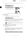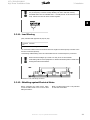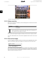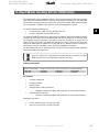
1
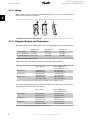
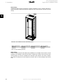
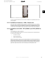
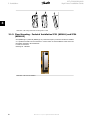
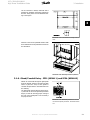
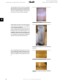
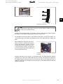
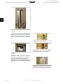
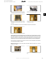
VLT® 5000/6000/8000
High Power Installation Guide
Contents
Contents
1. General Information
3
2. Preinstallation
7
Planning the Installation Site
7
Receiving the Frequency Converter
7
Transportation and Unpacking
7
Lifting
8
Shipping Weights and Dimensions
8
3. Installation
9
Mechanical Installation
9
Tools Needed
9
General Considerations
9
Installation in Enclosures - IP00 / Chassis units
19
Installation on the Wall - IP21 (NEMA 1) and IP54 (NEMA 12) Units
19
Floor Mounting - Pedestal Installation IP21 (NEMA1) and IP54 (NEMA12)
20
Gland/Conduit Entry - IP21 (NEMA 1) and IP54 (NEMA12)
21
IP21 Drip shield installation (D1 and D2 enclosure)
22
Electrical Installation
23
Control Wires
23
Power Connections
25
Mains connection
34
4. Duct Work Cooling Kit for IP00 Units
35
5. Installation on Pedestal - IP 21 / IP 54 Units
43
6. Start-Up Check
47
Connection Examples
47
Electrical Installation Procedures
47
Programming Procedures - VLT 5000
49
Programming Procedures - VLT 6000 HVAC, VLT 8000 AQUA and VLT 4000
49
Motor Start
50
7. Service During Use
51
8. Drawings
53
Index
58
MI.90.J2.02 - VLT® is a registered Danfoss trademark
1
VLT® 5000/6000/8000
High Power Installation Guide
1. General Information
1
2
MI.90.J2.02 - VLT® is a registered Danfoss trademark
VLT® 5000/6000/8000
High Power Installation Guide
1. General Information
1. General Information
1
1.1. Safety and General Information
1.1.1. General Warning
The voltage of the frequency converter is dangerous whenever the equipment is
connected to mains. Incorrect installation of the motor or the frequency converter
may cause damage to the equipment, serious personal injury or death.
Consequently, the instructions in this manual, as well as national and local rules and
safety regulations, must be complied with.
Installation in high altitudes:
By altitudes above 2 km, please contact Danfoss Drives regarding PELV.
1.1.2. Safety Regulations
1.
The frequency converter must be disconnected from mains if repair work is to be carried
out. Check that the mains supply has been disconnected and that the necessary time has
passed before removing motor and mains connections.
2.
The [STOP/RESET] key on the control panel of the frequency converter does not disconnect the equipment from mains and is thus not to be used as a safety switch.
3.
Correct protective earthing of the equipment must be established, the user must be protected against supply voltage, and the motor must be protected against overload in
accordance with applicable national and local regulations.
4.
The earth leakage currents are higher than 3.5 mA.
5.
Protection against motor overload is not included in the factory setting. If this function
is desired, set parameter 128 to data value ETR trip or data value ETR warning. For VLT
6000, VLT 8000 and VLT 4000, set parameter 117 to data value ETR trip or data value
ETR warning.
Note: The function is initialised at 1.16 x rated motor current and rated motor frequency
(see the Operating Instructions). The ETR functions provide class 20 motor overload
protection in accordance with NEC (North America).
6.
Do not remove the connections for the motor and main supply while the frequency converter is connected to mains. Check that the mains supply has been disconnected and
that the necessary time has expired before removing motor and mains connections.
7.
Please note that the frequency converter has more voltage inputs than L1, L2 and L3,
when loadsharing (linking of DC intermediate circuit) and external 24 V DC have been
installed. Check that all voltage inputs have been disconnected and that the necessary
time has passed before repair work is commenced.
8.
Cooling: The unit must be cooled properly. For IP 21 / NEMA 1 and IP 54 / NEMA 12
units, the gland plate at the bottom must be installed and it must be sealed properly.
Not installing it correctly will affect the internal cooling of the unit and cause unintended
over-temperature warnings and alarms.
9.
Do not tilt the frequency converter as the centre of gravity is high. Make sure it is fixed
to a floor stand, the wall, or another fixing point.
MI.90.J2.02 - VLT® is a registered Danfoss trademark
3
VLT® 5000/6000/8000
High Power Installation Guide
1. General Information
1
1.1.3. Warning Against Unintended Start
1.
The motor can be brought to a stop by means of digital commands, bus commands,
references or a local stop, while the frequency converter is connected to mains.
If personal safety considerations make it necessary to ensure that no unintended start
occurs, these stop functions are not sufficient.
2.
While parameters are being changed, the motor may start. Consequently, the stop key
[STOP/RESET] must always be activated, following which data can be modified.
3.
A motor that has been stopped may start if faults occur in the electronics of the frequency
converter, or if a temporary overload or a fault in the supply mains or the motor connection ceases.
1.1.4. Installation of Mechanical Brake (VLT 5000 and VLT 5000
FLUX)
Do not connect a mechanical brake to the output from the frequency converter before the relevant
parameters for brake control have been defined. (Select output in parameters 319, 321, 323 or
326 and cut-in current and frequency in parameters 223 and 225).
1.1.5. Use on Isolated Mains
See section RFI Switch in the Operating Instructions regarding use on isolated mains. It is important to follow the recommendations regarding installation on IT mains, including isolated delta
systems, since sufficient protection of the complete installation must be observed. Not taking care
using relevant monitoring for IT mains may result in damage.
Warning:
Touching the electrical parts may be fatal - even after the equipment has been disconnected from mains.
Also make sure that other voltage inputs have been disconnected, such as external
24 V DC, load-sharing (linkage of DC intermediate circuit), as well as the motor
connection for kinetic back-up.
D1 and D2 enclosures: Wait at least 20 minutes.
E1 enclosures: Wait at least 46 minutes.
4
MI.90.J2.02 - VLT® is a registered Danfoss trademark
VLT® 5000/6000/8000
High Power Installation Guide
1. General Information
Manual Objectives
The purpose of this manual is to provide the user with the necessary information to install and
perform the basic commissioning of the frequency converters. This manual should be read thoroughly before operating, servicing or initialising the drives. This manual is intended for use along
with the Operating Instructions for the relevant series of frequency converters.
1
Who Should Use This Manual
This manual is intended for qualified service personnel responsible for setting up and servicing
frequency converters. Qualified personnel have previous experience with frequency converters
and understand electrical fundamentals, programming procedures, required equipment and safety
precautions.
Organisation of This Manual
This manual is arranged in sections which deal with equipment installation and connection sequence. The order of tasks is arranged as follows:
• Safety instructions
• Preinstallation
• Selection of installation site
• Transportation and unpacking
• Mechanical installation
• Electrical installation
• Control cable routing
• Power cable routing
• Connection examples
• Electrical installation procedures (short form)
• Motor start
As the units are available in different enclosure sizes, depending on the rated output power, the
structure of the instruction is based on these enclosure variants.
380-460/480/500 V variants
Type
VLT 5000
VLT 5000 FLUX
VLT 6000 HVAC
VLT 8000 AQUA
VLT 4000 VT
(North America)
Voltage
380-500 V
380-500 V
380-460 V
380-480 V
380-460 V
AC
AC
AC
AC
AC
Enclosure D1
VLT 5122-5152
VLT 5122-5152
VLT 6152-6172
VLT 8152-8202
VLT 4152-4202
Enclosure D2
VLT 5202-5302
VLT 5202-5302
VLT 6222-6352
VLT 8252-8352
VLT 4252-4352
Enclosure E1
VLT 5352-5552
VLT 5352-5502
VLT 6402-6602
VLT 8452-8652
VLT 4452-4652
525-600/690 V supply
Type
VLT 5000
VLT 6000 HVAC
VLT 8000 AQUA
VLT 4000 VT
(North America)
Voltage
525-690 V
525-600 V
525-690 V
525-600 V
AC
AC
AC
AC
Enclosure D1
VLT 5042-5152
VLT 6102-6172
VLT 8052-8202
VLT 4102-4202
Enclosure D2
VLT 5202-5352
VLT 6222-6402
VLT 8252-8402
VLT 4252-4402
Enclosure E1
VLT 5402-5602
VLT 6502-6652
VLT 8502-8652
Detailed technical information about the product can be found in the Operating Instructions for
the respective frequency converter series.
MI.90.J2.02 - VLT® is a registered Danfoss trademark
5
VLT® 5000/6000/8000
High Power Installation Guide
2. Preinstallation
2
6
MI.90.J2.02 - VLT® is a registered Danfoss trademark
VLT® 5000/6000/8000
High Power Installation Guide
2. Preinstallation
2. Preinstallation
2
2.1.1. Planning the Installation Site
Before performing the installation it is important to plan the installation of the frequency converter.
Neglecting this may result in extra work during and after installation. Select the best possible
operation site by considering the following (see details on the following pages, and the respective
Operating Instructions and Design Guides):
•
Ambient operating temperature
•
Installation method
•
How to cool the unit
•
Position of the frequency converter
•
Cable routing
•
Ensure the power source supplies the correct voltage and necessary current
•
Ensure that the motor current rating is within the maximum current from the frequency
converter
•
If the frequency converter is without built-in fuses, ensure that the external fuses are
rated correctly.
2.1.2. Receiving the Frequency Converter
When receiving the frequency converter please make sure that the packaging is intact, and be
aware of any damage that might have occurred to the unit during transport. In case damage has
occurred, contact immediately the shipping company to claim the damage.
2.1.3. Transportation and Unpacking
Before unpacking the frequency converter it is recommended that it is located as close as possible
to the final installation site.
Remove the cardboard box and handle the frequency converter on the pallet, as long it is possible.
Remark: The card box cover contains a drilling master for the mounting holes.
Illustration 2.1: Mounting Template
MI.90.J2.02 - VLT® is a registered Danfoss trademark
7
VLT® 5000/6000/8000
High Power Installation Guide
2. Preinstallation
2.1.4. Lifting
Always lift the frequency converter in the dedicated lifting eyes. Use a bar to avoid bending the
lifting holes of the frequency converter.
2
Illustration 2.2: Recommended lifting method
2.1.5. Shipping Weights and Dimensions
The weight and dimensions of the frequency converter and packaging depend on the actual unit.
Enclosure D1
IP 00 / Chassis
91 (200)
IP 21 / NEMA Type 1 104 (229)
IP 54 / NEMA Type 12 104 (229)
Enclosure D2
138 (304)
151 (333)
151 (333)
Enclosure E1
277 (610)
313 (689)
272 (689)
Table 2.1: Shipping weight in kg (lbs)
Weight is specified as the maximum weight with all possible options included.
IP00 / Chassis
Enclosure D1
Enclosure D2
Enclosure E1
1220*650*570
(48*25.6*22.4)
1490*650*570
(58.7*25.6*22.4)
1705*831*736
(67.1*32.8*29.0)
IP21 / NEMA Type 1
IP54 / NEMA Type 12
1730*650*570
(53.9*25.6*22.4)
1730*650*570
(68.1*25.6*22.4)
2197*840*736
(86.5*33.1*29.0)
Table 2.2: Card board box size. Shipping dimensions (width * hight * depth in mm (in))
The units are shipped laying down, and the above dimensions are according to this. The dimensions include the skid where the box is mounted.
IP00 / Chassis
Enclosure D1
1046*408*373
(41*16.1*14.7)
IP21 / NEMA Type 1
IP54 / NEMA Type 12
1208*420*373
(47.5*16.5*14.7)
Enclosure D2
1327*408*373
(52.2*16.1*14.7)
1499*585*506
(59.0*23.0*19.9)
1588*420*373
(62.5*16.5*14.7)
2000*6000*494
(78.7*23.6*19.5)
Enclosure E1
Table 2.3: Drive dimensions (height * width * depth in mm (in))
8
MI.90.J2.02 - VLT® is a registered Danfoss trademark
VLT® 5000/6000/8000
High Power Installation Guide
3. Installation
3. Installation
3.1. Mechanical Installation
3
Preparation of the mechanical installation of the frequency converter must be done carefully to
ensure a proper result and to avoid additional work during installation. Start taking a close look
at the mechanical drawings at the end of this instruction to become familiar with the space demands.
3.1.1. Tools Needed
To perform the mechanical installation the following tools are needed:
•
Drilling machine with 10 or 12 mm drill
•
Tape measure
•
Wrench with relevant metric sockets (7-17 mm)
•
Extensions to wrench
•
Sheet metal punch for conduits or cable glands in IP 21 and IP 54 units
•
Lifting bar to lift the unit (rod or tube Ø 20 mm (0.75 inch)) able to lift minimum 400 kg
(880 lbs).
•
Crane or other lifting aid to place the frequency converter in position
•
A Torx T50 tool is needed to install the E1 enclosure in IP21 and IP54 enclosure variants.
3.1.2. General Considerations
Space
Ensure proper space above and below the frequency converter to allow airflow and cable access.
In addition space in front of the unit must be considered to open the door of the panels.
Illustration 3.1: Space in front of IP21/IP54 enclo-
Illustration 3.2: Space in front of IP21/IP54 enclo-
sure type D1 and D2.
sure type E1.
MI.90.J2.02 - VLT® is a registered Danfoss trademark
9
VLT® 5000/6000/8000
High Power Installation Guide
3. Installation
3
Illustration 3.3: Airflow direction and necessary space for cooling
Left: Enclosure IP21/54, D1 and D2.
Right: Enclosure IP00, D1, D2 and E1.
Illustration 3.4: Airflow direction and necessary space for cooling - Enclosure IP21/54, E1
10
MI.90.J2.02 - VLT® is a registered Danfoss trademark
VLT® 5000/6000/8000
High Power Installation Guide
3. Installation
Wire access
Ensure that proper wire access is present including necessary bending space. As the IP00 enclosure is open to the bottom wires must be fixed to the back panel of the enclosure where the
frequency converter is mounted, i.e. by using cable clamps.
Terminal locations(D1 and D2 enclosures)
Take the following position of the terminals into consideration when you design for cables access.
3
Illustration 3.5: Position of power connections
Illustration 3.6: Position of power connections - Disconnect
Be aware that the power cables are heavy and hard to bend. Consider the optimum position of
the frequency converter for ensuring easy installation of the cables.
MI.90.J2.02 - VLT® is a registered Danfoss trademark
11
VLT® 5000/6000/8000
High Power Installation Guide
3. Installation
A
B
C
D
E
F
G
H
I
J
K
L
M
N
O
P
Q
R
S
T
U
V
3
IP 00 / Chassis
Enclosure D1
119 (4.7)
68 (2.7)
15 (0.6)
20.7 (0.8)
363 (14.3)
293 (11.5)
215 (8.4)
131 (5.2)
48 (1.9)
347 (13.6)
277 (10.9)
326 (12.8)
243 (9.6)
159 (6.3)
261 (10.3)
170 (6.7)
120 (4.7)
98 (3.8)
301 (11.8)
245 (9.6)
189 (7.4)
260 (10.2)
Enclosure D2
122 (4.8)
68 (2.7)
16 (0.6)
22 (0.8)
363 (14.3)
293 (11.5)
218 (8.6)
135 (5.3)
51 (2.0)
354 (13.9)
270 (10.6)
326 (12.8)
243 (9.6)
159 (6.3)
261 (10.3)
170 (6.7)
120 (4.7)
93 (3.7)
324 (12.8)
255 (10.0)
185 (7.3)
273 (10.7)
IP 21 (NEMA 1) / IP 54 (NEMA 12)
Enclosure D1
Enclosure D2
277 (10.9)
379 (14.9)
227 (8.9)
326 (12.8)
173 (6.8)
273 (10.8)
179 (7.0)
279 (11.0)
370 (14.6)
370 (14.6)
300 (11.8)
300 (11.8)
222 (8.7)
226 (8.9)
139 (5.4)
142 (5.6)
55 (2.2)
59 (2.3)
354 (13.9)
361 (14.2)
284 (11.2)
277 (10.9)
334 (13.1)
334 (13.1)
250 (9.8)
250 (9.8)
167 (6.6)
167 (6.6)
261 (10.3)
260 (10.3)
170 (6.7)
169 (6.7)
120 (4.7)
120 (4.7)
256 (10.1)
350 (13.8)
308 (12.1)
332 (13.0)
252 (9.9)
262 (10.3)
196 (7.7)
192 (7.6)
260 (10.2)
273 (10.7)
Table 3.1: Cable positions as shown in drawings above. Dimensions in mm (inch).
12
MI.90.J2.02 - VLT® is a registered Danfoss trademark
VLT® 5000/6000/8000
High Power Installation Guide
3. Installation
Terminal locations - E1 enclosures
Take the following position of the terminals into consideration when designing the cable access.
3
Illustration 3.7: IP00 enclosure power connection positions
Illustration 3.8: IP00 enclosure power connection positions
MI.90.J2.02 - VLT® is a registered Danfoss trademark
13
VLT® 5000/6000/8000
High Power Installation Guide
3. Installation
3
Illustration 3.9: IP00 enclosure power connections positions of disconnect switch
Illustration 3.10: IP21 (NEMA Type 1) and IP54 (NEMA Type 12) enclosure power connection positions
14
MI.90.J2.02 - VLT® is a registered Danfoss trademark
VLT® 5000/6000/8000
High Power Installation Guide
3. Installation
3
Illustration 3.11: IP21 (NEMA type 1) and IP54 (NEMA type 12) enclosure power connection positions (detail
B)
Illustration 3.12: IP21 (NEMA type 1) and IP54 (NEMA type 12) enclosure power connection position of
disconnect switch
MI.90.J2.02 - VLT® is a registered Danfoss trademark
15
VLT® 5000/6000/8000
High Power Installation Guide
3. Installation
Note that the power cables are heavy and difficult to bend. Consider the optimum position of the
frequency converter for ensuring easy installation of the cables.
Each terminal allows use of up to 4 cables with cable lugs or use of standard box lug. Earth is
connected to relevant termination point in the drive.
3
Illustration 3.13: Terminal in details
Illustration 3.14: Position of earth terminals IP00
16
MI.90.J2.02 - VLT® is a registered Danfoss trademark
VLT® 5000/6000/8000
High Power Installation Guide
3. Installation
3
Illustration 3.15: Position of earth terminals IP21 (NEMA type 1) and IP54 (NEMA type 12)
Cooling
Cooling can be obtained in different ways, by using the cooling ducts in the bottom and the top
of the unit, by using the ducts in the backside of the unit or by combining the cooling possibilities.
Airflow
The necessary airflow over the heat sink must be secured. The flow rate is shown below.
Enclosure
IP00 / Chassis
IP21 / NEMA 1
IP54 / NEMA 12
D1 and D2
E1
D1 and D2
E1
Door fan / Top fan airflow
255 m3/h (150 cfm)
255 m3/h (150 cfm)
170 m3/h (100 cfm)
340 m3/h (200 cfm)
Airflow over heatsink
765 m3/h (450 cfm)
1444 m3/h (850 cfm)
765 m3/h (450 cfm)
1444 m3/h (850 cfm)
Table 3.2: Heat Sink Air Flow
MI.90.J2.02 - VLT® is a registered Danfoss trademark
17
VLT® 5000/6000/8000
High Power Installation Guide
3. Installation
Duct cooling
A dedicated option has been developed to optimise installation of IP00 / Chassis enclosed frequency converters in Rittal TS8 enclosures utilising the fan of the frequency converter for forced
cooling.
3
Illustration 3.16: Installation of IP00 in Rittal TS8 enclosure
Rittal TS8 Enclosure
1800 mm
2000 mm
Frame D1 Kit Part No. Frame D2 Kit Part No. Frame E1 Part No.
176F1824
176F1823
Not possible
176F1826
176F1825
176F1850
Table 3.3: Duct Kit Ordering Numbers
Back cooling
Using the channel from the back allows easy installation in for example control rooms. The unit
mounted to the backside of the enclosure allows a similar easy cooling of the units as the duct
cooling principle. The hot air is ventilated out of the back of the enclosure. This offers a solution
where the hot cooling air from the frequency converter does not cause heating of the control
room.
18
MI.90.J2.02 - VLT® is a registered Danfoss trademark
VLT® 5000/6000/8000
High Power Installation Guide
3. Installation
3
Illustration 3.17: Combined use of cooling principles
The above mentioned solution can of course also be combined for an optimised solution in the
actual installation.
3.1.3. Installation in Enclosures - IP00 / Chassis units
As the IP00 version is intended for panel mounting, it is important to know how to install the
frequency converter and utilise the possibilities for cooling the units. A detailed description of how
to install the frequency converter in a Rittal TS8 enclosure by using the installation kit can be found
in a later section of this Installation Guide. This can also be used as a guide for other installations.
3.1.4. Installation on the Wall - IP21 (NEMA 1) and IP54 (NEMA 12)
Units
This only applies for D1 and D2 enclosures.
It must be considered where to install the unit. Take the relevant points into consideration before
you select the final installation site.
•
Free space for cooling
•
Access to open the door
•
Cable entry from the bottom
Mark the mounting holes carefully using the mounting template on the wall and drill the holes as
indicated. Ensure proper distance to the floor and the ceiling for cooling. A minimum of 225 mm
(8.9 in) below the frequency converter is needed. Mount the bolts at the bottom and lift the
frequency converter up on the bolts. Tilt the frequency converter against the wall and mount the
upper bolts. Tighten all four bolts to secure the frequency converter against the wall.
MI.90.J2.02 - VLT® is a registered Danfoss trademark
19
VLT® 5000/6000/8000
High Power Installation Guide
3. Installation
3
Illustration 3.18: Lifting method for mounting drive on wall
3.1.5. Floor Mounting - Pedestal Installation IP21 (NEMA1) and IP54
(NEMA12)
IP21 (NEMA type 1) and IP54 (NEMA type 12) enclosed frequency converters can also be installed
on a pedestral. Details can be found later in a later section of this Installation Guide and in the
information included in the Pedestal kit.
D1 and D2 enclosures
Ordering No. 176F1827
Illustration 3.19: Drive on Pedestal
20
MI.90.J2.02 - VLT® is a registered Danfoss trademark
VLT® 5000/6000/8000
High Power Installation Guide
3. Installation
The E1 enclosure is always delivered with a
pedestal as standard. Install the pedestal on
the floor. Fixing holes are to be drilled according to this figure:
3
Illustration 3.20: Drill master for fixing holes in
floor.
Mount the drive on the pedestal and fix it with
the included bolts to the pedestal as shown on
the illustration.
Illustration 3.21: Mounting of drive to pedestal
3.1.6. Gland/Conduit Entry - IP21 (NEMA 1) and IP54 (NEMA12)
Cables are connected through the gland plate
from the bottom. Remove the plate and plan
where to place the entry for the glands or
conduits. Prepare holes in the marked area on
the drawing.
The gland plate must be fitted to the frequency converter to ensure the specified protection
degree, as well as ensuring proper cooling of
the unit. If the gland plate is not mounted, it
may trip the unit.
Illustration 3.22: Cable entry viewed from the bottom of the frequency converter - Enclosure D1 and
D2.
MI.90.J2.02 - VLT® is a registered Danfoss trademark
21
VLT® 5000/6000/8000
High Power Installation Guide
3. Installation
3
Illustration 3.23: Cable entry seen from the bottom of the frequency converter - Enclosure E1.
The bottom plate of the E1 enclosure can be mounted from either in or outside of the enclosure,
allowing flexibility in the installation process, i.e. if mounted from the bottom the glands and cables
can be mounted before the frequency converter is placed on the pedestal.
Illustration 3.24: Mounting of bottom plate, E1 enclosure.
3.1.7. IP21 Drip shield installation (D1 and D2 enclosure)
To comply with the IP21 rating, a separate
drip shield is to be installed as explained below:
•
Remove the two front screws
•
Insert the drip shield and replace
screws
•
Torque the screws to 5,6 Nm (50 inlbs)
Illustration 3.25: Drip shield installation.
22
MI.90.J2.02 - VLT® is a registered Danfoss trademark
VLT® 5000/6000/8000
High Power Installation Guide
3. Installation
3.2. Electrical Installation
3.2.1. Control Wires
Connect the wires as described in the Operating Instruction for the frequency converter.
Remember to connect the shields in a proper
way to ensure optimum electrical immunity.
3
Control cable routing
Tie down all control wires to the designated
control cable routing.
Illustration 3.26: Wire path for control wiring.
Fieldbus connection
Connections are made to the relevant options
at the control card. For details see the relevant
fieldbus instruction. The cable must be placed
to the left inside the frequency converter and
tied down together with other control wires.
In the IP 00 (Chassis) and IP 21 (NEMA 1)
units it is also possible to connect the fieldbus
from the top of the unit as shown on the picture below. On the IP 21 (NEMA 1) unit a
cover plate must be removed.
Illustration 3.27: Top connection for fieldbus.
Installation of 24 Volt external DC Supply
Torque: 0.5 - 0.6 Nm (5 in-lbs)
Screw size: M3
No.
35, 36
Function
24 V external DC supply
24 V external DC supply can be used as low-voltage supply to the control card and any option
cards installed. This enables full operation of the LCP (incl. parameter setting) without connection
to mains. Please note that a warning of low voltage will be given when 24 V DC has been connected; however, there will be no tripping. If 24 V external DC supply is connected or switched
on at the same time as the mains supply, a time of min. 200 msec. must be set in parameter 120
Start delay.
MI.90.J2.02 - VLT® is a registered Danfoss trademark
23
VLT® 5000/6000/8000
High Power Installation Guide
3. Installation
A pre-fuse of min. 6 Amp, slow-blow, can be fitted to protect the external 24 V DC supply. The
power consumption is 15-50 W, depending on the load on the control card.
Use 24 V DC supply of type PELV to ensure correct galvanic isolation (type PELV) on
the control terminals of the frequency converter.
3
Relay output
Torque: 0.5 - 0.6 Nm (5 in-lbs)
Screw size: M3
No.
1-3
4, 5
24
Function
Relay output, 1+3 break, 1+2
make. See the Operating Instructions.
Relay output, 4+5 make. See
the Operating Instructions.
MI.90.J2.02 - VLT® is a registered Danfoss trademark
VLT® 5000/6000/8000
High Power Installation Guide
3. Installation
3.2.2. Power Connections
Cabling and Fusing
The power cable connections are situated as shown below. Dimensioning of cable cross section
must be done in accordance with the current ratings and local legislation. See the Operating Instructions for details.
3
For protection of the frequency converter the recommended fuses must be used or the unit must
be with built-in fuses. Recommended fuses can be seen in the Operating Instructions. Always
ensure that proper fusing is made according to local regulation.
Illustration 3.28: Compact IP 00 (Chassis), enclosure D1
MI.90.J2.02 - VLT® is a registered Danfoss trademark
25
VLT® 5000/6000/8000
High Power Installation Guide
3. Installation
3
Illustration 3.29: Compact IP 21 (NEMA 1) and IP 54 (NEMA 12), enclosure D1 with disconnect fuse and RFI
filter
Illustration 3.30: Compact IP 00 (Chassis) with disconnect, fuse and RFI filter, enclosure D2
26
MI.90.J2.02 - VLT® is a registered Danfoss trademark
VLT® 5000/6000/8000
High Power Installation Guide
3. Installation
3
Illustration 3.31: Compact IP 21 (NEMA 1) and IP 54 (NEMA 12) with disconnect, fuse and RFI filter, enclosure D2
Illustration 3.32: Compact IP 00 (Chassis), enclosure E1
MI.90.J2.02 - VLT® is a registered Danfoss trademark
27
VLT® 5000/6000/8000
High Power Installation Guide
3. Installation
3
Illustration 3.33: Compact IP 00 (Chassis) with disconnect, fuse and RFI filter, enclosure E1
Illustration 3.34: Position of earth terminals IP00
28
MI.90.J2.02 - VLT® is a registered Danfoss trademark
VLT® 5000/6000/8000
High Power Installation Guide
3. Installation
3
Illustration 3.35: Compact IP 21 (NEMA 1) and IP 54 (NEMA 12) enclosure E1
Illustration 3.36: Position of earth terminals IP21 (NEMA type 1) and IP54 (NEMA type 12)
MI.90.J2.02 - VLT® is a registered Danfoss trademark
29
VLT® 5000/6000/8000
High Power Installation Guide
3. Installation
3.2.3. Earthing
The following basic issues need to be considered when installing a frequency converter, so as to
obtain electromagnetic compatibility (EMC).
3
•
Safety earthing: Please note that the frequency converter has a high leakage current and
must be earthed appropriately for safety reasons. Apply local safety regulations.
•
High-frequency earthing: Keep the earth wire connections as short as possible.
Connect the different earth systems at the lowest possible conductor impedance. The lowest possible conductor impedance is obtained by keeping the conductor as short as possible and by using
the greatest possible surface area.
The metal cabinets of the different devices are mounted on the cabinet rear plate using the lowest
possible HF impedance. This avoids having different HF voltages for the individual devices and
avoids the risk of radio interference currents running in connection cables that may be used between the devices. The radio interference will have been reduced.
In order to obtain a low HF impedance, use the fastening bolts of the devices as HF connection
to the rear plate. It is necessary to remove insulating paint or similar from the fastening points.
3.2.4. Extra Protection (RCD)
ELCB relays, multiple protective earthing or earthing can be used as extra protection, provided
that local safety regulations are complied with.
In the case of an earth fault, a DC content may develop in the faulty current.
If ELCB relays are used, local regulations must be observed. Relays must be suitable for protection
of 3-phase equipment with a bridge rectifier and for a brief discharge on power-up.
See also the section Special Conditions in the relevant Design Guide.
3.2.5. RFI Switch
Mains supply isolated from earth:
If the frequency converter is supplied from an isolated mains source (IT mains, floating delta and
grounded delta) or TT/TN-S mains with grounded leg, the RFI switch is recommended to be turned
off (OFF)1). For further reference, see IEC 364-3. In case optimum EMC performance is needed,
parallel motors are connected or the motor cable length is above 25 m, it is recommended to set
the switch in ON position.
In OFF position, the internal RFI capacities (filter capacitors) between the chassis and the intermediate circuit are cut off to avoid damage to the intermediate circuit and to reduce the earth
capacity currents (according to IEC 61800-3).
Please also refer to the application note VLT on IT mains, MN.90.CX.02. It is important to use
isolation monitors that are capable for use together with power electronics (IEC 61557-8).
The RFI switch is not to be operated with mains connected to the unit. Check that
the mains supply has been disconnected before operating the RFI switch.
Open RFI switch is only allowed at factory set switching frequencies.
30
MI.90.J2.02 - VLT® is a registered Danfoss trademark
VLT® 5000/6000/8000
High Power Installation Guide
3. Installation
The RFI switch connects the capacitors galvanically to earth.
1) Not required with 525-600/690 V drives; therefore not possible.
3
3.2.6. Torque
When tightening all electrical connections it is
very important to tighten with the correct torque. Too low or to high torque result in a bad
electrical connection. Use a torque wrench to
ensure correct torque
Illustration 3.37: Always use a torque wrench to
tighten the bolts.
Enclosure
D1 and D2
Terminal
Mains
Motor
Load sharing
Brake
Mains
Motor
Load sharing
Brake
E1
Torque
19 Nm (168 in-lbs)
Bolt size
M10
9.5 (84 in-lbs)
M8
19 NM (168 in-lbs)
M10
9.5 (84 in-lbs)
M8
Table 3.4: Torque for terminals
3.2.7. Shielded Cables
It is important that shielded and armoured cables are connected in a proper way to ensure high
EMC immunity and low emissions. Connection can be made with either cable glands or clamps.
•
EMC cable glands: Generally available cable glands can be used to ensure an optimum
EMC connection.
•
EMC cable clamp: Clamps allowing easy connection are supplied with the frequency converter.
3.2.8. Motor cable
The motor must be connected to terminals U/T1/96, V/T2/97, W/T3/98. Earth to terminal 99. All
types of three-phase asynchronous standard motors can be used with a frequency converter unit.
MI.90.J2.02 - VLT® is a registered Danfoss trademark
31
VLT® 5000/6000/8000
High Power Installation Guide
3. Installation
The factory setting is for clockwise rotation with the VLT frequency converter output connected
as follows:
Terminal No. Function
96, 97, 98, Mains U/T1, V/T2, W/T3
99
Ground/Earth
3
• Terminal U/T1/96 connected to U-phase
• Terminal V/T2/97 connected to V-phase
• Terminal W/T3/98 connected to W-phase
The direction of rotation can be changed by switching two phases in the motor cable.
3.2.9. Brake Cable
(Only standard with brake and extended with brake. Typecode: SB, EB, DE, PB).
Terminal No. Function
81, 82
Brake resistor terminals
The connection cable to the brake resistor must be screened. Connect the screen by means of
cable clamps to the conductive back plate at the frequency converter and to the metal cabinet of
the brake resistor.
Size the brake cable cross-section to match the brake torque. See also Brake instructions, MI.
90.FX.YY and MI.50.SX.YY for further information regarding safe installation.
Please note that voltages up to 1099 V DC, depending on the supply voltage, may
occur on the terminals.
3.2.10. Brake Resistor Temperature Switch
Torque: 0.5-0.6 Nm (5 in-lbs)
Screw size: M3
This input can be used to monitor the temperature of an externally connected brake resistor. If
the input between 104 and 106 opens, the frequency converter will trip on alarm 29. If the connection is closed between 104 and 105, the frequency converter will trip on alarm 29.
Normally closed: 104-106 (factory installed jumper)
Normally open: 104-105
Terminal No.
106, 104, 105
32
Function
Brake resistor temperature switch.
MI.90.J2.02 - VLT® is a registered Danfoss trademark
VLT® 5000/6000/8000
High Power Installation Guide
3. Installation
If the temperature of the brake resistor gets too high and the thermal switch drops
out, the frequency converter will stop braking. The motor will start coasting.
A KLIXON switch must be installed that is `normally closed'. If this function is not
used, 106 and 104 must be short-circuited together.
3
3.2.11. Load Sharing
(Only extended with typecode EB, EX, DE, DX).
Terminal
No.
88, 89
Function
Loadsharing
The connection cable must be screened and the max. length from the frequency converter to the
DC bar is 25 metres (82 feet).
Load sharing enables linking of the DC intermediate circuits of several frequency converters.
Please note that voltages up to 1099 V DC may occur on the terminals.
Load sharing calls for extra equipment. For further information please consult Loadsharing Instructions MI.50.NX.XX.
Illustration 3.38: Load sharing connection.
3.2.12. Shielding against Electrical Noise
Before mounting the mains power cable,
mount the EMC metal cover to ensure best
EMC performance.
NOTE: The EMC metal cover is only included
in units with an RFI filter.
MI.90.J2.02 - VLT® is a registered Danfoss trademark
33
VLT® 5000/6000/8000
High Power Installation Guide
3. Installation
3
Illustration 3.39: Mounting of EMC shield.
3.2.13. Mains connection
Mains must be connected to terminals 91, 92 and 93. Earth/ground is connected to the terminal
to the right of terminal 93.
Terminal No.
91, 92, 93
94
Function
Mains R/L1, S/L2, T/L3
Ground/Earth
Check the name plate to ensure that the mains voltage of the VLT frequency converter matches the power supply of your plant.
Ensure that the power supply can supply the necessary current to the VLT frequency converter.
If the unit is without built-in fuses, ensure that the appropriate fuses have the correct current
rating.
3.2.14. External Fan Supply
In case DC supplies the frequency converter or the fan must run independently of the power
supply, an external power supply can be applied. The connection is done to the power card.
Terminal
No.
100, 101
102, 103
Function
Auxiliary supply S, T
Internal supply S, T
The connector located on the power card provides the connection of line voltage for the cooling
fans. The fans are connected from factory to be supplied form a common AC line (jumpers between 100-102 and 101-103). If external supply is needed, the jumpers are removed and the
supply is connected to terminals 100 and 101.
34
MI.90.J2.02 - VLT® is a registered Danfoss trademark
VLT® 5000/6000/8000
High Power Installation Guide
4. Duct Work Cooling Kit for IP00 Units
4. Duct Work Cooling Kit for IP00 Units
This chapter deals with the installation of IP00 / chassis enclosed frequency converters with duct
work cooling kits in Rittal enclosures. These kits are designed and tested to be used with Rittal
TS8 enclosures 1800 mm (Frame D1 and D2 only) and 2000 mm height. Other enclosure heights
are not supported. In addition to the enclosure a 200 mm base/plinth is required.
The minimum enclosure dimension is:
•
D1 and D2 frame: Depth 500 mm and width 600 mm.
•
E1 frame: Depth 600 mm and width 800 mm.
4
The maximum depth and width are as required by the installation. When using multiple frequency
converters in one enclosure it is recommended that each drive is mounted on its own back panel
and supported along the mid-section of the panel. These duct work kits do not support the “in
frame” mounting of the panel (see Rittal TS8 catalogue for details). The duct work cooling kits
listed in the table below are suitable for use only with IP 00 / Chassis frequency converters in
Rittal TS8 IP 20 and UL and NEMA 1 and IP 54 and UL and NEMA 12 enclosures.
The duct work shown is for D1 and d2 enclosures. The duct work for E1 enclosures has a different
look, but is installed in the same way.
For the E1 enclosures it is important to mount the plate at the absolute rear of the
Rittal enclosure due to the weight of the frequency converter.
Ordering Information
Rittal TS-8 Enclosure
1800 mm
2000 mm
Frame D1 Kit Part No. Frame D2 Kit Part No. Frame E1Part No.
176F1824
176F1823
Not possible
176F1826
176F1825
176F1850
Kit Contents
•
Ductwork components
•
Mounting hardware
•
Gasket material
•
Delivered with D1 and D2 frame kits:
•
•
175R5639 - Mounting templates and top/bottom cut out for Rittal enclosure.
Delivered with E1 frame kits:
•
175R1036 - Mounting templates and top/bottom cut out for Rittal enclosure.
All fasteners are either:
•
10 mm, M5 Nuts torque to 2.3 Nm (20 in-lbs)
•
T25 Torx screws torque to 2.3 Nm (20 in-lbs)
MI.90.J2.02 - VLT® is a registered Danfoss trademark
35
VLT® 5000/6000/8000
High Power Installation Guide
4. Duct Work Cooling Kit for IP00 Units
This illustration shows the full size template
included with the kit and two drawings that
may be used to locate the cutouts for the enclosure top and bottom plates. The duct work
may also be used to locate the openings.
4
Illustration 4.1: Templates
Install gasket material on the back openings
of the frequency converter prior to installation
on the enclosure back panel.
Use the template provided with the kit (shown
above) and install the frequency converter on
the back panel of the Rittal enclosure. The
template is referenced to the top-left corner
of the back panel. Therefore the template may
be used with any size back panel and both the
1800 mm and 2000 mm high enclosures.
Illustration 4.2: Openings on rear not used in this
application
Before installing the back panel in the enclosure assemble the gasket on both sides of the
bottom duct adapter as shown below, and install on the bottom of the frequency converter.
Illustration 4.3: Bottom duct adapter
Illustration 4.4: Bottom duct adapter with gasket
installed
36
MI.90.J2.02 - VLT® is a registered Danfoss trademark
VLT® 5000/6000/8000
High Power Installation Guide
4. Duct Work Cooling Kit for IP00 Units
Illustration 4.5: Bottom duct adapter installed
4
Illustration 4.6: Side view
NB!
Install the bottom plate after the frequency converter has been installed on the back
to assure proper gasket coverage.
Install the two mounting brackets on the frequency converter chassis and then install the bottom
duct adapter on the bottom of the frequency converter as shown below.
The installation of the bottom plate is easier while the back panel is outside the enclosure. The
curved leading edge of the bottom duct adapter is to the front of the frequency converter and
down.
Before installing the back panel with the frequency converter in the Rittal TS8 enclosure
remove and discard the rearmost 5 screws
(see illustration below) located on the top cover of the frequency converter. The holes will
be used to fasten the top ductwork with longer
screws provided with the kit.
Illustration 4.7: Top of IP 00 / Chassis frequency
converter
Install the back panel in the enclosure, see illustration below. Use Rittal PS4593.000 brackets
(minimum one per side at the middle of the frequency converter) with appropriate support strip
for additional support of the back panel. For the D2 and E1 frame use two supports per side. If
additional components are mounted on the same back panel, consult Rittal manual for additional
support requirements.
MI.90.J2.02 - VLT® is a registered Danfoss trademark
37
VLT® 5000/6000/8000
High Power Installation Guide
4. Duct Work Cooling Kit for IP00 Units
4
Illustration 4.8: Frequency converter installed in
cabinet
The top ductwork cover is composed of the
following pieces as shown below. From left to
right: 1. top duct closing plate, 2. frequency
converter bracket, 3. duct, 4. duct vented top
cover.
Illustration 4.9: Top duct assembly
Illustration 4.11: The top duct work partially assembled with frequency converter bracket
Illustration 4.10: Top duct work and enclosure top
installed
Temporarily install the top duct section as
shown above. Use the top duct cover piece to
mark the enclosure top for the opening.
Alternatively the mounting template (supplied
drawing) can be used to make the enclosure
cut-out.
Illustration 4.12: Rittal enclosure top with cutout
Standard Rittal enclosures top is cut. Gasket is not
used on the cutout. Gasket is part of duct work.
38
MI.90.J2.02 - VLT® is a registered Danfoss trademark
VLT® 5000/6000/8000
High Power Installation Guide
4. Duct Work Cooling Kit for IP00 Units
Illustration 4.13: Gasket folds over the edge to
Illustration 4.14: Top duct installed
form seal between the duct and top vented cover
4
Illustration 4.15: Gasket applied to both sides of
Illustration 4.16: Top duct ready to be installed on
the frequency converter bracket and duct vented
the frequency converter
top cover.
For the final installation of the duct work, assemble the top duct as shown above.
Illustration 4.17: Top duct assembled with gasket
Gasket is applied to several surfaces as shown (see exploded view of components) The top duct
closing plate is left off for the installation of the duct work on the frequency converter. The top
duct work is attached to the frequency converter using existing holes on the top cover of the
frequency converter. Use the longer T25 screws provided with the kit in the existing frequency
converter top cover holes. The duct work will fit over the frequency converter mounting bolts.
Once the ductwork is attached to the frequency converter, the duct closing plate can be attached.
The top ductwork assembly is complete.
Apply the gasket to the top duct closing plate and install. Install the enclosure top. Top duct
installation is complete.
Illustration 4.18: Top duct installed
Illustration 4.19: Top duct closing plate with gasket
MI.90.J2.02 - VLT® is a registered Danfoss trademark
39
VLT® 5000/6000/8000
High Power Installation Guide
4. Duct Work Cooling Kit for IP00 Units
Illustration 4.20: Top duct closing plate installed
Illustration 4.21: Enclosure top installed
4
Illustration 4.22: Top view of Rittal enclosure
The bottom duct assembly pieces. Refer to drawing showing exploded view of duct work components. Gasket is installed as shown. Assemble the bottom duct less the cover. Assembly includes
the mounting of 3 angle brackets on the front and sides of the partially assembled bottom duct.
The bottom duct collar is bolted to the duct using 3 - T25 screws in the outermost holes of the
brackets. Tighten the screws to compress the gasket.
Illustration 4.23: Bottom ductwork pieces
Illustration 4.24: Bottom ductwork partially assembled
Illustration 4.25: Completely assembled bottom
duct work
The duct assembly is used to mark the bottom
cutout. Temporarily install the bottom duct
work as shown to the right. Use the inside of
the ductwork to mark the bottom of the enclosure for the opening.
40
MI.90.J2.02 - VLT® is a registered Danfoss trademark
VLT® 5000/6000/8000
High Power Installation Guide
4. Duct Work Cooling Kit for IP00 Units
Illustration 4.26: Temporarily install duct work to
4
mark cutout on the gland
The cutout is made on the innermost gland
plate. The remaining two gland plates must be
removed for the installation of the bottom
duct assembly.
Illustration 4.27: Enclosure bottom cutout
The bottom duct work is rotated into place as shown. The bottom ductwork is a tight fit by design.
The upper part of the duct fits under the bottom duct adapter and requires a tight fit which with
the gasket material maintains the IP 54 and UL and NEMA 12 rating.
Illustration 4.28: Bottom ductwork installed
Illustration 4.29: Installation of bottom duct
After the bottom ductwork has been positioned in place, remove the three T25 screws
from the outer holes in the mounting brackets
on the sides and front of ductwork and move
them to the inner holes of the same brackets.
Tighten the three screws to the specified torque. The bottom duct work is not fastened to
Rittal enclosure.
Illustration 4.30: Move mounting screws from the
outer hole to the inner hole
Install the front cover of the duct and the cable clamp base if used. Install the two remaining gland plates.
MI.90.J2.02 - VLT® is a registered Danfoss trademark
41
4. Duct Work Cooling Kit for IP00 Units
Illustration 4.31: Bottom duct installed.
4
42
MI.90.J2.02 - VLT® is a registered Danfoss trademark
VLT® 5000/6000/8000
High Power Installation Guide
VLT® 5000/6000/8000
High Power Installation Guide
5. Installation on Pedestal - IP 21 / IP 54 Units
5. Installation on Pedestal - IP 21 / IP 54 Units
The frequency converter can also be installed on the floor. A dedicated floor stand is designed for
that purpose. It can only be used for units produced after week 50, 2004 (serial number
XXXXXG504).
This section describes the installation of a pedestal unit available for the VLT series frequency
converters frames D1 and D2. This is a 200 mm high pedestal that allows these frames to be floor
mounted. The front of the pedestal has openings for input air to the power components.
5
The frequency converter gland plate must be installed to provide adequate cooling air to the
control components of the frequency converter via the door fan and to maintain the IP21/NEMA
1 or IP54/NEMA 12 degrees of enclosure protections.
There is one pedestal that fits both frames D1 and D2.
Required Tools
Required Tools:
•
Socket wrench with 7-17 mm sockets
•
T30 Torx Driver
Torques:
•
M6 - 4.0 Nm (35 in-lbs)
•
M8 - 9.8 Nm (85 in-lbs)
•
M10 - 19.6 Nm (170 in-lbs)
Kit Contents:
•
Pedestal parts
•
Instruction manual
Illustration 5.1: Drive on pedestal.
MI.90.J2.02 - VLT® is a registered Danfoss trademark
43
VLT® 5000/6000/8000
High Power Installation Guide
5. Installation on Pedestal - IP 21 / IP 54 Units
The kit contains a U-shaped piece, a vented
front cover, 2-side covers, two front brackets
and the required hardware to assemble See
the exploded view of the installation (drawing
175R5641).
Illustration 5.2: Pedestal parts
The pedestal has been partially assembled.
Before installing the drive on to the pedestal
it is important to anchor the pedestal to the
floor using the four pedestal mounting holes.
The holes can accommodate up to M12 bolts
(not included in the kit).
CAUTION: The drives are top heavy and may
fall over if the pedestal is not anchored to the
floor.
The entire assembly may also be supported by
using the drive top mounting holes to anchor
to a wall structure.
5
Illustration 5.3: Pedestal partially assembled
The completely assembled pedestal with vented front cover and two side covers installed.
Multiple frequency converters may be mounted side by side. The interior side closing
plates are left off.
NOTE: The front and side cover mounting
screws are now recessed M6 Torx socket flat
head screws.
Illustration 5.4: Final assambled pedestal.
Install the frequency converter by lowering on
to the pedestal. The frequency converter must
overhang the front of the pedestal to clear the
retaining bracket on the rear of the pedestal.
After the frequency converter has been placed
on the pedestal, slide the frequency converter
engages the retaining bracket on the pedestal
and mount screws as shown.
Illustration 5.5: Mounting of drive to pedestal.
44
MI.90.J2.02 - VLT® is a registered Danfoss trademark
VLT® 5000/6000/8000
High Power Installation Guide
5. Installation on Pedestal - IP 21 / IP 54 Units
Illustration 5.6: Two nuts at rear side.
5
Illustration 5.7: Three front screws.
Illustration 5.8: Frame D2 with pedestal installed
MI.90.J2.02 - VLT® is a registered Danfoss trademark
45
VLT® 5000/6000/8000
High Power Installation Guide
6. Start-Up Check
6
46
MI.90.J2.02 - VLT® is a registered Danfoss trademark
VLT® 5000/6000/8000
High Power Installation Guide
6. Start-Up Check
6. Start-Up Check
6.1.1. Connection Examples
For details see the Operating Instructions of the specific frequency converters.
6
Brake terminals 81 and 82 are not available in VLT 6000, VLT 8000 and VLT 4000 series.
* Depends on parameter settings.
6.1.2. Electrical Installation Procedures
The following procedure will guide you through a correct electrical installation of your VLT frequency converter.
Before you start, please read the safety instructions on the first page of this instruction.
Note that the user is responsible, that the VLT frequency converter, motor and other units are
installed according to recognized local regulations. Pay special attention to cable dimensioning,
pre-fuses, earthing and over-current protection.
1. Mechanical installation check
Check the following before the electrical installation:
MI.90.J2.02 - VLT® is a registered Danfoss trademark
47
VLT® 5000/6000/8000
High Power Installation Guide
6. Start-Up Check
1.
Check for proper ambient operating conditions. See Derating for ambient temperature
in the relevant Design Guide.
2.
Check for free flow of cooling air.
3.
Check that no visible damage has occurred to the crate and drive during transport.
2. Load sharing connection
1.
Install the wire for DC+ to terminal 89.
2.
Install the wire for DC- to terminal 88.
Note that voltages up to 1099 V DC will occur on the terminals when power is connected.
6
3. Brake resistor (only VLT 5000)
1.
Install the wire for R+ to terminal 82.
2.
Install the wire for R- to terminal 81.
4. Motor connection
1.
Install earth from the motor to the earthing point.
2.
Install W from the motor to terminal W/T3/98.
3.
Install V from the motor to terminal V/T2/97.
4.
Install U from the motor to terminal U/T1/96.
5. EMC shield
1.
Mount the EMC shield between the motor and mains supply connections.
NOTE: Only supplied on drives with an RFI filter.
6. Mains connection
1.
Check that the mains voltage matches the VLT frequency converter nominal input voltage.
2.
Ensure that the power supply can supply the necessary current to the VLT frequency
converter, see Technical data in the relevant Operating Instructions.
3.
Install earth from the power supply to the earthing point.
4.
Install line 1 from the power supply to terminal R/L1/91.
5.
Install line 2 from the power supply to terminal S/L2/92.
6.
Install line 3 from the power supply to terminal T/L3/93.
7. Power up
Check the following before you power up the VLT frequency converter:
48
1.
Check for proper mains fuses. See Technical data in the relevant Operating Instructions.
2.
Check for a proper earthing.
3.
Check for proper mains, load sharing, brake and motor connection.
4.
Check that there are no tools in the enclosure.
MI.90.J2.02 - VLT® is a registered Danfoss trademark
VLT® 5000/6000/8000
High Power Installation Guide
6. Start-Up Check
Close the doors and connect the power to the VLT frequency converter. The green voltage indicator lamp (ON) on the control panel is activated when the VLT frequency converter receives
voltage.
The VLT frequency converter can now be programmed via the control panel.
Note that in parameter 620 Operating mode you can select Function with de-activated inverter
[1]. After cycling the power the parameter is active. This means that without the motor shaft
running you can control the influence of the control signal on the control card.
NOTE: Not a safety function.
Wait at least 20 minutes (D1 and D2 frames) and 46 minutes (E1 frames) before
you open the doors, after the VLT frequency converter has been disconnected from
mains.
6.1.3. Programming Procedures - VLT 5000
6
Programming the VLT 5000
The frequency converter is programmed over the control panel.
Press [QUICK MENU].
The Quick Menu appears in the display. Choose parameters by means of ↑ and ↑.
Press [CHANGE DATA] to change parameter value. Data values are changed using ↑ and ↑.
Press → or → to move the cursor.
Press [OK] to save parameter setting.
Set the desired language in parameter 001.
Set motor parameters according to the motor plate:
Motor
Motor
Motor
Motor
Rated
power
voltage
frequency
current
motor speed
Parameter
Parameter
Parameter
Parameter
Parameter
102
103
104
105
106
Set frequency interval and ramp times.
Min. reference
Max. reference
Ramp up time
Ramp down time
Parameter
Parameter
Parameter
Parameter
204
205
207
208
Set Operation site, parameter 002 for Local.
6.1.4. Programming Procedures - VLT 6000 HVAC, VLT 8000 AQUA
and VLT 4000
The frequency converter is programmed over the control panel.
Press [QUICK MENU].
The Quick Menu appears in the display. Choose parameters by means of ↑ and ↑.
Press [CHANGE DATA] to change parameter value. Data values are changed using ↑ and ↑.
Press → or → to move the cursor. Press [OK] to save your parameter setting.
MI.90.J2.02 - VLT® is a registered Danfoss trademark
49
VLT® 5000/6000/8000
High Power Installation Guide
6. Start-Up Check
Set the desired language in parameter 001.
Set motor parameters according to the motor plate:
Motor
Motor
Motor
Motor
Rated
power
voltage
frequency
current
motor speed
Parameter
Parameter
Parameter
Parameter
Parameter
102
103
104
105
106
Set frequency interval and ramp times.
Min. reference
Max. reference
Ramp up time
Ramp down time
Relay 1 function
Relay 2 function
6
Parameter
Parameter
Parameter
Parameter
Parameter
Parameter
204
205
207
208
323
326
6.1.5. Motor Start
VLT
VLT
VLT
VLT
5000
4000
6000
8000
Press [START] to start the motor
Press [HAND START] to start the motor
Set motor speed in parameter 003 by VLT 5000.
Set motor speed with the +/- keys on LCP of VLT 6000, VLT 8000 and VLT 4000.
Check if the direction of rotation is as shown in the display. It can be changed by swapping two
phases of the motor cable.
VLT
VLT
VLT
VLT
5000
4000
6000
8000
Press [STOP] to stop the motor
Press [OFF/STOP] to stop the motor
Select total or reduced Automatic Motor Adaptation (AMA) in parameter 107. For further description of AMA, please see the manual.
Press [START] to start the Automatic Motor Adaptation (AMA).
Press [DISPLAY/STATUS] to leave the Quick Menu.
50
MI.90.J2.02 - VLT® is a registered Danfoss trademark
VLT® 5000/6000/8000
High Power Installation Guide
7. Service During Use
7. Service During Use
Preventive maintenance
To ensure a long and problem-free use of the frequency converter we recommend that you perform preventive maintenance.
Cleaning of filters IP 54 (NEMA 12)
Filters in the door must be serviced on a regular basis. The interval must be defined from installation to installation to ensure proper function based on the dust contents in the air.
Cleaning of the heat sink
During normal use it is not necessary to clean the heat sink. The forced airflow will keep the fins
free from dust and other substances. In case the environment is very dusty, the heat sink can be
cleaned by blowing compressed air over the heat sink from the top or the bottom of the frequency
converter.
Remember to switch off the frequency converter before cleaning.
7
Checking connections
Measuring the temperature on power connections with a thermal camera or infrared meter is
recommended as a preventive maintenance activity. Early detection of changes in the power connections to the frequency converter allows relevant action to avoid overheating connections and
in worst case stops.
Checking temperatures and running conditions
We recommend that you note the typical data during operation like:
•
Motor current at specified frequencies, i.e. 40 and 50 Hz
•
Heat sink temperature at a defined ambient temperature
•
Intermediate voltage
•
....
Based on these registrations it is possible to follow trends that indicate if maintenance is necessary
or other changes to the operating conditions.
MI.90.J2.02 - VLT® is a registered Danfoss trademark
51
VLT® 5000/6000/8000
High Power Installation Guide
8. Drawings
8
52
MI.90.J2.02 - VLT® is a registered Danfoss trademark
VLT® 5000/6000/8000
High Power Installation Guide
8. Drawings
8. Drawings
•
Mechanical detailed drawing
8
MI.90.J2.02 - VLT® is a registered Danfoss trademark
53
VLT® 5000/6000/8000
High Power Installation Guide
8. Drawings
8
54
MI.90.J2.02 - VLT® is a registered Danfoss trademark
VLT® 5000/6000/8000
High Power Installation Guide
8. Drawings
8
MI.90.J2.02 - VLT® is a registered Danfoss trademark
55
VLT® 5000/6000/8000
High Power Installation Guide
8. Drawings
8
56
MI.90.J2.02 - VLT® is a registered Danfoss trademark
VLT® 5000/6000/8000
High Power Installation Guide
8. Drawings
8
MI.90.J2.02 - VLT® is a registered Danfoss trademark
57
VLT® 5000/6000/8000
High Power Installation Guide
Index
Index
A
Airflow
17
B
Back Cooling
18
Brake Cable
32
Brake Resistor Temperature Switch
32
C
Cabling
25
Cooling
17
D
Drip Shield Installation
22
Duct Cooling
18
Duct Work Cooling Kits
35
E
Earthing
30
Elcb Relays
30
Electrical Installation Procedures
47
External Fan Supply
34
F
Fieldbus Connection
23
Floor Mounting
20
Fusing
25
I
Installation Of 24 Volt External Dc Supply
23
Installation On Pedestal
43
Isolated Mains
4
It Mains
30
L
Lifting
8
Load Sharing
33
M
Mains Connection
34
Mechanical Brake
4
Mechanical Installation
9
Motor Cable
31
Motor Start
50
O
Ordering
35
P
Pedestal Installation
20
Power Connections
11
Programming Procedures
49
R
Rfi Switch
58
30
MI.90.J2.02 - VLT® is a registered Danfoss trademark
VLT® 5000/6000/8000
High Power Installation Guide
Index
S
Service During Use
51
Shielded Cables
31
T
Terminal Locations
11
Torque
31
U
Unintended Start
4
Unpacking
7
W
Weight And Dimensions
8
Wire Access
11
MI.90.J2.02 - VLT® is a registered Danfoss trademark
59