1
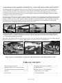
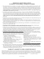
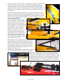
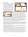
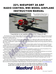
ALBATROS D.III
INSTRUCTION MANUAL
(Shown with optional pilot bust, motor and propeller.)
Specifications:*
Wingspan ............................................................................................ Upper – 40 inches
Lower – 39 inches
Wing Area ................................................................................... Upper – 265 sq. inches
Lower – 152 sq. inches
Length ................................................................................................................. 30 inches
Flying weight ..................................................................................................... 30~33 oz.
Brushless motor (Not included) .................................................. 166 Watts, 1,200 RPM/V
(Recommended motor: Maxford USA C2812-1200 or equivalent)
Brushless electronic speed control w/BEC (Not included) .................... 18 A for 3S Li-Po
(Recommended electronic speed control: Maxford USA Uranus 18 A or equivalent)
Propeller (Not included) .......................................................................................... SF 9×6
Battery (Not included) ................................ 11.1V, 1,300~2,100 mAh, 15C Li-Po battery
Radio system (Not included) .......................... Minimum of 4 channels with 4 mini servos
(Recommended servos: Maxford USA SG-90 or equivalent)
*(Dimensions and weights are approximate.)
Entire Contents © Copyright 2008
Congratulations on your acquisition of Maxford USA’s version of the Albatros D.III from World War I.
The Albatros D.III was a single-seat biplane used by the Imperial German Army Air Service and the Austro-Hungarian Air
Service during the First World War. It was heavily armed with twin synchronized, forward-firing 7.92 mm LMG 08/15
machine guns and powered by a 180 hp Mercedes 6-cylinder inline, water-cooled engine (unusual for the time), and its
streamlined radiator, mounted on the top wing, was offset slightly to starboard so that combat damage would not result in
scalding water being released over the pilot.
The prototype D.III first flew in August 1916 and was quickly recognized for its outstanding maneuverability and rate of climb.
Like most fighters, the D.III was prone to spinning. However, its recovery was straightforward, and German aces including
Manfred von Richthofen, Ernst Udet, Erich Löwenhardt, Kurt Wolff, and Karl Emil Schäfer credited the D.III as being both
pleasant and easy to fly. Nearly all pilots of the time used unique combinations of colors and markings to identify their
individual aircraft, as illustrated by the aircraft pictured below, circa 1917:
Because of the D.III’s V-shaped interplane struts, pilots of the British Royal Flying Corps often referred to the D.III as the
"V-strutter" and they accorded it a very high level of respect, especially after their horrific losses during “Bloody April” of
1917 to the superior Albatros D.III fighters.
More than 1,800 Albatros D.IIIs were built between 1916 and 1918, and Albatros D.IIIs continued to be successfully deployed
throughout the balance of war, even after such newer fighters as those pictured below were introduced:
Albatros D.V
Fokker Dr.I
Fokker D.VII
Enjoy the pride of ownership and of flying this high-quality model of the famous Albatros D.III!
TABLE OF CONTENTS
Important safety precautions .................................
Warranty, liability waiver, and return policy ........
This Albatros D.III model’s special features ........
Parts list ................................................................
Power system ........................................................
3
3
4
4
5
Tail group, machine guns & windshield .............. 5
Ailerons and wings ............................................... 7
Rudder & elevator servos, landing gear,
cabane struts, receiver, spinner,
and final adjustments ......................................... 9
Page 2 of 11 pages
IMPORTANT SAFETY PRECAUTIONS
TO PROTECT YOUR MODEL, YOURSELF & OTHERS
1. This product should not be considered a toy, but rather a sophisticated, working model that functions much like a fullscale airplane. Because of its performance capabilities, this product, if not assembled and operated correctly, could
cause injury to you or spectators and damage to property. Maxford USA provides you with a high-quality, thoroughly
tested model airplane kit with assembly instructions. However, the quality and capabilities of your finished model
airplane depends on how you build it, and your safety depends on how you use and fly it. Any testing or flying of this
model airplane is done entirely at your own risk.
2. Assemble the model airplane according to the instructions. Take time to build it STRAIGHT, TRUE and STRONG.
We recommend that you do not alter or modify the model, as doing so may result in an unsafe or unworkable model.
In a few cases the instructions may differ slightly from the photos. In those instances the written instructions should be
considered as correct. If you have any question about the instructions, before you proceed with assembly of this
product, contact us at (562) 529-3988, Monday through Friday, except national holidays, between 8:30 AM to 5 PM
Pacific time.
3. Install the R/C system and other components in such a way that this model airplane passes all ground safety/range tests
and ensure that all controls operate smoothly and correctly.
4. Check the operation of this model airplane before every flight to ensure that all equipment is still operating correctly
and that the model has remained structurally sound. Also, before every flight check the clevises and other connectors;
replace any found damaged or defective.
5. If you are not an experienced R/C pilot or have not flown this type of model before, we recommend that you get the
assistance of an experienced R/C pilot.
6. Throughout the lifetime of this model, use only the supplied Maxford USA or same-sized motor, electronic speed
control, and a new or well-maintained R/C radio system and recommended Li-Po battery.
7. While this kit has been flight-tested to meet or exceed our rigid performance and reliability standards in normal use, if
you plan to perform any extremely high-stress flying, such as racing or advanced aerobatics, or if you plan to install a
larger motor than included, you (the buyer or user of this product) are solely responsible for taking steps to reinforce
the high-stress points and/or substitute hardware that is more suitable for such increased stresses.
8. LITHIUM BATTERY HANDLING & USAGE: WARNING!! Read the entire instruction sheet included with the
battery. Failure to follow all instructions could result in permanent damage to the battery, its surroundings, and bodily
harm! If you crash this model airplane, check whether the Li-Po battery is damaged.
Do NOT attempt to use and do not attempt to re-charge a damaged Li-Po battery.
ONLY use a Li-Po approved charger.
NEVER charge in excess of 4.2V per cell.
(NEVER use a NiCd/NiMH charger!)
NEVER discharge below 2.5V per cell.
ALWAYS set the charger’s output to match the battery’s
NEVER allow battery temp. to exceed 150° F (65° C).
voltage and mAh ratings.
NEVER charge at currents greater than 1C (for example,
ALWAYS charge through the battery’s “charge” connector.
in the case of a 1,300 mAh battery, that’s 1.3 amps).
(NEVER charge through the “discharge” leads.)
NEVER trickle charge.
ALWAYS charge in a fireproof location.
NEVER disassemble or modify pack wiring in any way
NEVER place on combustible materials or leave unattended
or puncture cells.
during charge or discharge.
ALWAYS KEEP OUT OF REACH OF CHILDREN.
9. This model of the Albatros D.III includes some carbon-fiber reinforced or fiberglass parts. Be warned that carbonfiber and fiberglass dust may cause eye, skin and respiratory tract irritation. So, if you grind, drill or sand such parts,
always wear safety goggles, a particle mask and rubber gloves, and never blow into such a part to remove carbon-fiber
or fiberglass dust, as the dust may blow back into your eyes.
WARRANTY, LIABILITY WAIVER, AND RETURN POLICY
Maxford USA guarantees this kit to be free from defects in material and workmanship at the time of purchase. All of our
products have been inspected in our factory and are checked again when shipped from our warehouse. However, Maxford
USA cannot directly control any of the materials you may use nor your final-assembly process. Therefore, Maxford USA
CANNOT in any way guarantee the performance of your finished model airplane.
[Continued on next page.]
Page 3 of 11 pages
Furthermore, in purchasing this product, you (the buyer or user of this product) exempt, waive, and relieve Maxford USA from
all current or future liability for any personal injury, property damage, or wrongful death, and if you (the buyer or user of this
product) are involved in any claim or suit, you will not sue Maxford USA or any of its representatives.
If you do not fully accept the above liability and waiver, you may request a return merchandise authorization number (RMA#)
as explained in item 2, below.
If you think there is any shipping damage or missing part(s), please review our after-sales service and return policy as outlined
below.
1. Inspect your order upon delivery for any shipping damage or missing part. If you find a problem you must contact us
within 10 days from receipt of your purchase by calling (562) 529-3988, Monday through Friday, except holidays,
between the hours of 8:30 AM and 5 PM Pacific time. During this telephone conversation, and with your support, we
will determine how to resolve your concern. (Note: Maxford USA Li-Po batteries are sold without warranty and are
not eligible for return or credit.)
2. To request an RMA#, call (562) 529-3988, Monday through Friday, except holidays, between the hours of 8:30 AM to
5 PM Pacific time. If we elect to issue you an RMA#, you must clearly mark this RMA# on the outside of the package.
(No return or exchange will be authorized after 10 days from the date of your receipt of the product; any package
delivered to us without a Maxford USA RMA# is subject to being returned to the sender, as received, with return
postage payable upon delivery.) Returned merchandise must be in its original condition as received from Maxford
USA, with no assembly or modification, in the original packing materials, complete with all manuals and accessories.
Return shipping and insurance charges must be prepaid by you, the buyer.
3. Returned merchandise that is accepted by Maxford USA for credit is subject to a 10% to 20% restocking fee. (The
final amount will be determined by Maxford USA upon receipt and examination of the returned merchandise.)
Return Address:
Maxford USA RC Model Mfg, Inc.
15247 Texaco Avenue
Paramount, CA 90723-3917
(IMPORTANT: If issued by Maxford USA RC Model Mfg, Inc.
print the RMA# on the package near the above address.)
THIS ALBATROS D.III MODEL’S SPECIAL FEATURES
•
•
•
•
•
•
Scale dummy-engine, wing-mounted radiator and machine guns.
Shock-absorbing, spring-loaded landing gear and tail skid.
True-to-scale, large-sized spinner.
Completely pre-covered & pretrimmed, with all control surfaces prehinged
and all mounting openings predrilled/precut.
Each aileron is separately operated by its own, in-wing servo.
The battery hatch is strongly secured by a rare-earth magnet.
PARTS LIST
1. Items you must supply to complete the Albatros D.III:
• Outer-rotor motor, matching electronic speed control with BEC, and SF 9x6 propeller.
• 3 cell 1,300~2,100 mAh, 20C Li-Po battery and appropriate Li-Po battery charger.
• Electrical connectors for battery to electronic speed control (ESC) and ESC to motor, with heat-shrink
tubing, and elevator and rudder mechanical/servo connectors (i.e., Du-Bro E/Z Connectors or equivalent).
• 4 ea. SG-90 or equivalent mini servos with servo Y-connector and 3 ea. 12” servo-wire extensions.
• Receiver and transmitter (minimum of 4 channels for aileron, rudder, elevator and throttle).
• Thin cyanoacrylate adhesive (CA), 5-minute epoxy, windshield adhesive, double-sided foam tape,
black electrical tape, masking tape, and misc. common hand tools.
Page 4 of 11 pages
2. Items included in the Albatros D.III package:
• Fuselage with magnetic battery hatch, elevator, rudder and aileron pushrods with Z-bend connectors.
• Left and right wing sets with preattached interplane struts, preinstalled guy wires, and wing joiner rods.
• Vertical and horizontal stabilizers with prehinged rudder and elevator.
• Preformed and spring-loaded landing gear, wheels, wheel collars and spring loaded tail skid.
• All required control horns and self-threading and machine-type screws (except those supplied with servos).
• Over-sized scale spinner.
• This illustrated instruction manual.
ALBATROS D.III ASSEMBLY INSTRUCTIONS
Step 1: Install the power system.
1. Remove and set aside the battery compartment cover.
2. Insert the vertical oil-line into the hole at the front-top of the fuselage as you insert the
in-line dummy 6 cylinder engine fully down into its opening. Attach the dummy engine
with one screw through the pre-drilled hole in the battery compartment floor, and secure
the engine with a drop of CA adhesive where the cylinders’ mounting base touches the
fuselage cross members.
3. Mount the motor from
inside the firewall, then
connect the ESC’s 3 wires to
the motor’s 3 wires in any,
arbitrary order. (AT THIS
TIME DO NOT CONNECT
THE ESC TO THE BATTERY;
ALSO, DO NOT ATTACH A
PROPELLER TO THE MOTOR.)
Use double-sided foam tape to
attach the ESC to the fuselage
cross members behind the
motor. (Leave space between the motor and ESC to ensure the back of the
motor does not touch the ESC.)
Step 2: Mount the tail group, machine guns & windshield.
4.
Insert the control horns into the pre-cut slots in the bottom of the elevator and
the left side of the rudder, and secure each control horn with a drop or two of
CA adhesive.
5.
Remove masking tape from both pushrods inside the battery compartment.
Pull the elevator (lower) pushrod out from the rear of the fuselage not more
than 6 inches, and twist and turn the horizontal stab. with its prehinged
elevator to attach the elevator’s control horn onto the Z-bend in the elevator’s
pushrod. Insert the horizontal stabalizer into its mating
horizontal slot at the
rear of the fuselage
and slide the horiz.
stab. forward within
the slot until the
elevator’s hingeline just meets the
tail end of the
fuselage.
Page 5 of 11 pages
6.
Look down into the vertical stabalizer’s mounting slot at the top-rear of the fuselage
and carefully position the horiz. stab. so its two small rectangular openings are
aligned with the two same-sized openings in the fuselage’s horizontal cross
member. Once these slots are perfectly aligned, secure the horizontal stab. to
the fuselage’s cross member by applying a few drops of CA adhesive into each
set of two slots.
7.
Pull the rudder (upper) pushrod out from the rear of the fuselage not more than
6 inches, lay the vertical stab. with its pre-hinged rudder on its right side, and twist
and turn the vertical stab. with its prehinged rudder to attach the rudder’s control
horn onto the Z-bend in the rudder’s pushrod. Place the vertical stab. vertically
above its mounting slot
at the top rear of the fuselage
and mix and apply a coat of 5-minute
epoxy to all surfaces of each of the two
wooden tabs projecting from the base
of the vertical stab. Lower and insert the
vertical stabalizer’s wooden tabs into the
slots in the horiz. stab. and fuselage
cross member. Adjust the vertical
stabalizer’s position to ensure there is
no friction between the bottom of the
rudder and the top of the fuselage, then
use alcohol to clean any excess 5-min.
epoxy from the top of the fuselage, the
vertical stabalizer, and rudder. Allow 15
minutes for the epoxy to cure.
8.
Mix and apply a coat of 5-minute epoxy to all sides of the tab
that projects from the top of the pre-assembled tail skid
assembly. Insert the tail skid’s tab into the slot under the
horiz. stab.in the fuselage. Ensure the tail skid assembly
is perpendicular to the horiz. stab. and clean any excess
5-min. epoxy from the tail skid and fuselage. Allow 15
minutes for the epoxy to cure.
9.
Position the 2 machine guns into the slots on their mounting
base and secure them with a few drops of CA adhesive.
As shown below, insert the tab on the machine-gun mounting base
into the pre-cut slot in front of the cockpit in the top of the fuselage,
and secure it to the fuselage with a few drops of CA adhesive. Insert
the windshield’s tabs into the pre-cut slots in the top of the fuselage
behind the machine guns, and secure the windshield to the fuselage
with windshield adhesive or a minimal application of CA adhesive.
Page 6 of 11 pages
Step 3: Ailerons and wings.
10. On the starboard (right) upper wing, remove 4 screws
and lift out the right upper wing’s servo mounting
hatch-plate. Use the predrilled servo mounting holes
in the servo mounting hatch-plate and hardware
supplied by the servo manufacturer to install a
Maxford USA SG-90 or equivelant mini-servo.
11. Remove 4 small radiator-mounting screws (one at
each corner of the lower radiator panel) to expose
a rectangular hole in the wing’s covering material.
12. Connect one(1) 12-inch servo-wire extension to
each of the two(2) female connectors on a Y-cable.
Insert the female connector from one extension cable
through the opening in the wing’s center rib, guide
it into the opening for the aileron servo (right servo well), and connect it to the aileron servo.
(Note: To guide the servo extensions into the servo wells through both
the left and right upper wing panels, you may use the preinstalled string
to PULL the servo-wire extension through the wing and into the servo
well; however, you might find it easier to use masking tape to
temporarily attach the extension’s female connector to the end of a
length of straight coat hanger or heavier wire, and use the wire to PUSH
the extension’s connector through the wing and into the servo well.)
13. Guide the Y-cable’s central wire joint and its male connector into the wing through the opening in the right upper
wing’s center rib. Use a pair of long-nosed pliers to reach into the opening and pull the Y-cable’s male connector
out of the wing through the rectangular opening. Dress the excess servo wire to fit inside the servo well, and reinstall the right upper wing’s servo mounting hatch-plate (with attached aileron servo) using 4 screws.
14. Insert a control horn into the precut slot in the right aileron and secure by applying a drop or two of CA adhesive.
Insert an aileron control rod’s Z-bend into the aileron control horn. Use a small piece of masking tape to
temporarily secure the aileron in neutral alignment with the wing. Insert the Z-bend of a short pushrod into a hole
in the aileron servo’s arm. Slide a piece of heat-shrink tubing over the aileron pushrod and over the short
pushrod, so both these pushrods are captured inside the heat-shrink tubing.
15. Carefully apply the heat for a few seconds from an electric soldering iron or a woodburning tool along the entire
length of the heat-shrink tubing. (Note: Be careful to shrink but not burn the tubing; Be careful to NOT heat the
wing’s covering material nor the loosely hanging interplane guy wires!) Use a pair of side-cutting or diagonalcutting pliers to trim the aileron pushrod’s excess length. Remove the masking tape that was appied to hold the
aileron in neutral alignment with the wing.
16. On the left upper wing, remove 4 screws and lift out the servo mounting hatch-plate. Use the predrilled servo
mounting holes in the servo mounting hatch- plate and hardware supplied by the servo manufacturer to install a
Maxford USA SG-90 or equivelant mini-servo.
17. Insert the remaining/dangling female connector from the extension through the opening in the left upper wing’s
center rib. Follow the instructions in the ‘Note’ in step 12 to guide the extension through the wing and into the
left servo well. Connect the extension to the aileron servo. Dress the excess servo wire inside the servo well and
re-install the left upper wing’s servo mounting hatch-plate (with attached aileron servo) using 4 screws.
18. Per the instructions in steps 14 and 15: Insert a control horn into the precut slot in the left aileron and secure by
applying a drop or two of CA adhesive; insert an aileron control rod’s Z-bend into the aileron control horn;
temporarily secure the aileron in neutral alignment; insert the Z-bend of a short pushrod into a hole in the aileron
servo’s arm, insert a piece of heat-shrink tubing over the aileron pushrod and the short pushrod; shrink the tubing;
trim the aileron pushrod’s excess length; and remove the masking tape from the left aileron and wing.
Page 7 of 11 pages
19. Insert the Y-cable’s male connector through the rectangular opening in the bottom
of the radiator, and return the radiator to its original position with 4 screws. Using
black tape, wrap the exposed portion of the Y-connector’s wire.
(The Y-connector’s wire should be black from where it exits the radiator to where
it terminates at its male connector.)
20. Using the two largest carbon fiber
rods, slide the two upper wing
panels together. Place the upper
wing assembly bottom-side-up,
and lower the fuselage toward the
upper wing as you fit the center
cabane struts fully into the
matching openings on the
fuselage. (The cabane struts fit
snugly, so they must be pressed
firmly, all the way into the angled
openings on both sides of the fuselage.)
21. Insert the two smaller carbon fiber rods into one of the two
lower wing panels, then insert that wing panel into its matching
fuselage opening so that the carbon rods project out the other
side of the fuleslage. Guide the projecting carbon fiber rods
into the openings on the opposite lower wing panel, and slide
the two lower wing panels together inside the fuselage. Secure
the lower wing to the fuselage by snugging (do not overtighten) two black machine screws into the blind nuts that are pre-installed inside the fuselage.
22. Attach the remaining, third 12-inch servo extension’s female connector to the male end of the Y-cable hanging
from the radiator. Route the male end of the extension into the fuselage through the round hole located between
the engine and the machine guns. Pull the connection of the Y-connector and extension cable far enough into
the fuselage so only the Y-cable’s black wire is visible between the
radiator and the fuselage. (This black wire now simulates one of
two “water pipes” between the dummy radiator and engine.)
23. Using the adjacent radiator hole, install a black plastic tube (with
wire inside to give it shape) between the radiator and the opening in
the front of the dummy engine. (This black tube now simulates the
second “water pipe” between the radiator and the engine.)
24. Anchor and tighten the prestrung guy wires by inserting one screw
into the attachment point on each side of the fuselage …
(Attachment point for the black plastic tube
at the front of the dummy engine.)
Page 8 of 11 pages
Step 4: Rudder & elevator servos, landing gear, cabane struts, receiver, spinner & final adjustments.
25. Install the elevator and rudder servos using their precut slots,
the predrilled mounting-screw holes, and the hardware
supplied by the servo manufacturer. Connect the elevator
and rudder pushrods to the servo arms using Du-Bro Heavy
Duty E/Z connectors or equivelant.
26. Attach the preassembled landing gear by inserting its two
bent wires into the precut holes on either side of the battery
hatch. Secure the landing gear’s rear cross member to the
fuselage behind the lower wing by installing two(2) preshaped metal straps and inserting 4 screws through each
metal strap into the predrilled holes in the fuselage. Secure
these eight(8) landing-gear screws with a drop of CA
adhesive applied to each. Add a drop of light machine oil to
each of the shock absorbers. Check the wheel collets to
ensure that each wheel is secure on its axle.
27. Tighten all 10 of the machine-screw-and-nut
assemblies anchoring the cabane struts to the wings.
Ensure these connectors will not come loose by
adding a drop of Locktite (or CA adhesive) to each.
28. Install your radio receiver within or behind the battery
compartment. (For example, a micro-sized receiver
may be mounted on top of the speed control with
double-sided foam tape IF your ESC and motor do not
produce excessive RF-noise and IF you are careful to
ensure there is enough space between the motor, ESC
and receiver so the motor does not rub against the ESC
and/or the receiver.)
Page 9 of 11 pages
29. Charge and install your Li-Po battery. Check/adjust servo centering, direction, end-point adjustments and propellerrotation direction. Once the ailerons have been adjusted and checked to their centered/neutral positions, secure them
by applying a drop of CA adhesive into the heat-shrink tubing at each end of the aileron pushrods. If the motor runs
backwards, switch any 2 of the 3 ESC to motor connections. Please review your radio’s instruction manual if you
require assistance with any radio-related servo-adjustment questions.
30. Use the prop. nut and related hardware supplied with your motor to mount your propeller onto the backplate of the
Albatros D.III’s special, large-size spinner; then, securely tighten this propeller-backplate assembly onto the motor’s
shaft, as shown below. Attach the red dome-shaped spinner to the propeller-backplate assembly by inserting (but not
over-tightening) 4 screws into the pre-installed nuts on the backplate.
31. Close the battery compartment cover and check the model’s center of gravity (CG). If necessary, try moving the
ESC, receiver, and/or battery, or add weight to the nose or tail, to ensure the CG is 3 to 3¼ inches behind the leading
edge of the upper wing.
32. Recommended setups and final adjustments before flying …
Aileron and elevator control throws with a Computer Radio: Set linkages for max. possible deflections and soften
the aileron’s and elevator’s control throws by selecting
60% (or more) exponential, and 30% for the rudder.
Non-Computer Radio:
Low rates
High rates
Ailerons …….. + ½ inch ………. + 1 inch
Elevator …….. + ¾ inch ………. + 1 inch
Rudder ……… + ¾ inch ………. + 1 inch
Trim adjustments: You will probably discover that the ailerons & rudder require no adjustments (they will remain
centered, as assembled); however, the elevator will likely need some down trim (up to ¼ inch)
due to this model’s hi-lift, undercamber wings and throttle/speed settings chosen by the pilot.
Congratulations, assembly is finished!
Final pre-flight checks at the field:
1. Double-check that all screws and connections are secure, but do not overtighten the lower wing bolts (step 21).
2. Double-check the control directions of the ailerons, elevator and rudder (i.e., pull the right stick toward you
and the elevator should deflect upwards; push the right stick to the left and the left aileron should deflect
upwards and the right aileron should deflect downwards; push the left stick right and the rudder should
deflect to the right as viewed from the rear of the fuselage).
3. Check the airplane’s CG and, if necessary, try moving the ESC, receiver, or battery, or add weight to the nose or tail,
to ensure the CG is 3 to 3¼ inches behind the leading edge of the upper wing.
4. As with all radio-controlled model airplanes, this model must pass the radio range ground check recommended by
your radio’s manufacturer, or you may not safely fly.
5. When you are ready to fly, always be in the habit of moving your transmitter’s throttle and its trim control to
minimum, turn on the transmitter; then, connect the airplane’s battery to the ESC.
REMEMBER: A ROTATING PROPELLER IS DANGEROUS!
Page 10 of 11 pages
REMINDER: AN IMPORTANT NOTICE TO OUR CUSTOMERS!
• ALWAYS SWITCH THE TRANSMITTER ON (WITH ITS THROTTLE & TRIM ALL THE
WAY DOWN) BEFORE CONNECTING THE BATTERY TO THE ESC, AND ALWAYS
RETURN THE THROTTLE TO MINIMUM AND DISCONNECT THE BATTERY FROM
THE ESC BEFORE SWITCHING THE TRANSMITTER OFF.
• HANDLE THE MODEL WITH EXTREME CARE WHENEVER THE BATTERY IS
CONNECTED TO THE ESC.
• STAY CLEAR OF THE PROPELLER AND THE PROPELLER’S ARC.
This product is NOT just a toy.
Any testing or flying of this model airplane is done entirely at your own risk.
Order replacement parts, servos, batteries, brushless motors,
electronic speed controls, and a wide variety of high-quality RC hobby items
online at http://www.maxfordusa.com
PLEASE ENJOY YOUR HOBBY AND FLY SAFELY!
Distributed by:
Maxford USA RC Model Mfg, Inc.
15247 Texaco Avenue
Paramount, CA 90723-3917
Telephone (voice)
(562) 529-3988
FAX
(562) 562-6988
Toll free (orders only) (866) 706-8288
Web site
Manual written by: Curt Sidles
http://www.maxfordusa.com Special Thanks Marti Sidles
Page 11 of 11 pages