1
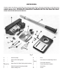
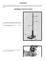
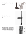
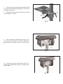
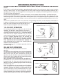
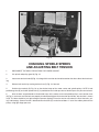
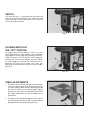
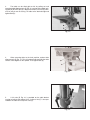
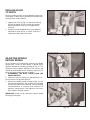
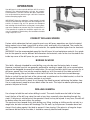
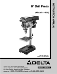
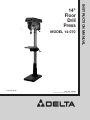
MODEL 14-070
Dated 6-30-95
PART NO. 1046995
©
Delta Machinery International Machinery Corp. 1995
INSTRUCTION MANUAL
14"
Floor
Drill
Press
TABLE OF CONTENTS
SAFETY RULES
3
ADDITIONAL SAFETY RULES FOR DRILL PRESSES
4
UNPACKING
5
CLEANING
6
ASSEMBLY INSTRUCTIONS
6-9
FASTENING DRILL PRESS TO A SUPPORTING SURFACE
9
MOTOR SPECIFICATIONS AND ELECTRICAL REQUIREMENTS
Motor Specifications
10
Power Connections
10
Extension Cords
10
Grounding Instructions
11
SPINDLE SPEEDS
12
CHANGING SPINDLE SPEEDS AND ADJUSTING BELT TENSION
13
SWITCH
14
LOCKING SWITCH IN THE “OFF” POSITION
14
TABLE ADJUSTMENTS
14-15
DRILLING HOLES TO DEPTH
16
ADJUSTING SPINDLE RETURN SPRING
16
OPERATION
Correct Drilling Speeds
17
Boring In Wood
17
Drilling In Metal
17
WARRANTY
SAFETY RULES
Woodworking can be dangerous if safe and proper operating procedures are not followed. As with all machinery, there
are certain hazards involved with the operation of the product. Using the machine with respect and caution will considerably lessen the possiblity of personal injury. However, if normal safety precautions are overlooked or ignored, personal injury to the operator may result. Safety equipment such as guards, push sticks, hold-downs, featherboards, goggles, dust masks and hearing protection can reduce your potential for injury. But even the best guard won’t make up
for poor judgment, carelessness or inattention. Always use common sense and exercise caution in the workshop. If a
procedure feels dangerous, don’t try it. Figure out an alternative procedure that feels safer. REMEMBER: Your personal
safety is your responsibility.
This machine was designed for certain applications only. Delta Machinery strongly recommends that this machine not
be modified and/or used for any application other than that for which it was designed. If you have any questions relative to a particular application, DO NOT use the machine until you have first contacted Delta to determine if it can or
should be performed on the product.
DELTA INTERNATIONAL MACHINERY CORP.
MANAGER OF TECHNICAL SERVICES
246 ALPHA DRIVE
PITTSBURGH, PENNSYLVANIA 15238
(IN CANADA: 644 IMPERIAL ROAD, GUELPH, ONTARIO N1H 6M7)
WARNING: FAILURE TO FOLLOW THESE RULES
MAY RESULT IN SERIOUS PERSONAL INJURY
1. FOR YOUR OWN SAFETY, READ INSTRUCTION
MANUAL BEFORE OPERATING THE TOOL. Learn the
tool's application and limitations as well as the specific hazards peculiar to it.
2. KEEP GUARDS IN PLACE and in working order.
3. ALWAYS WEAR EYE PROTECTION.
4. GROUND ALL TOOLS. If tool is equipped with threeprong plug, it should be plugged into a three-hole electrical
receptacle. If an adapter is used to accommodate a twoprong receptacle, the adapter lug must be attached to a
known ground. Never remove the third prong.
5. REMOVE ADJUSTING KEYS AND WRENCHES.
Form habit of checking to see that keys and adjusting
wrenches are removed from tool before turning it “on.”
6. KEEP WORK AREA CLEAN. Cluttered areas and
benches invite accidents.
7. DON'T USE IN DANGEROUS ENVIRONMENT. Don't
use power tools in damp or wet locations, or expose them
to rain. Keep work area well-lighted.
8. KEEP CHILDREN AND VISITORS AWAY. All children
and visitors should be kept a safe distance from work area.
9. MAKE WORKSHOP CHILDPROOF - with padlocks,
master switches, or by removing starter keys.
10. DON'T FORCE TOOL. It will do the job better and be
safer at the rate for which it was designed.
11. USE RIGHT TOOL. Don't force tool or attachment to
do a job for which it was not designed.
12. WEAR PROPER APPAREL. No loose clothing, gloves,
neckties, rings, bracelets, or other jewelry to get caught in
moving parts. Nonslip footwear is recommended. Wear
protective hair covering to contain long hair.
13. ALWAYS USE SAFETY GLASSES. Wear safety glasses (must comply with ANSI Z87.1). Everyday eyeglasses
only have impact resistant lenses; they are not safety glasses. Also use face or dust mask if cutting operation is dusty.
14. SECURE WORK. Use clamps or a vise to hold work
when practical. It's safer than using your hand and frees
both hands to operate tool.
15. DON'T OVERREACH. Keep proper footing and balance at all times.
16. MAINTAIN TOOLS IN TOP CONDITION. Keep tools
sharp and clean for best and safest performance. Follow
instructions for lubricating and changing accessories.
17. DISCONNECT TOOLS before servicing and when
changing accessories such as blades, bits, cutters, etc.
18. USE RECOMMENDED ACCESSORIES. The use of
accessories or attachments not recommended by Delta
may cause hazards or risk of injury to persons.
19. REDUCE THE RISK OF UNINTENTIONAL STARTING. Make sure switch is in “OFF” position before plugging in power cord.
20. NEVER STAND ON TOOL. Serious injury could
occur if the tool is tipped or if the cutting tool is accidentally contacted.
21. CHECK DAMAGED PARTS. Before further use of
the tool, a guard or other part that is damaged should be
carefully checked to ensure that it will operate properly
and perform its intended function - check for alignment
of moving parts, binding of moving parts, breakage of
parts, mounting, and any other conditions that may affect
its operation. A guard or other part that is damaged
should be properly repaired or replaced.
22. DIRECTION OF FEED. Feed work into a blade or
cuttter against the direction of rotation of the blade or
cutter only.
23. NEVER LEAVE TOOL RUNNING UNATTENDED.
TURN POWER OFF. Don't leave tool until it comes to a
complete stop.
24. DRUGS, ALCOHOL, MEDICATION. Do not operate
tool while under the influence of drugs, alcohol or any
medication.
25. MAKE SURE TOOL IS DISCONNECTED FROM
POWER SUPPLY while motor is being mounted, connected or reconnected.
26. WARNING: The dust generated by certain woods
and wood products can be injurious to your health.
Always operate machinery in well ventilated areas and
provide for proper dust removal. Use wood dust collection systems whenever possible.
ADDITIONAL SAFETY RULES
FOR DRILL PRESSES
1. WARNING: DO NOT operate your drill press until it is
completely assembled and installed according to the
instructions.
2. IF YOU ARE NOT thoroughly familiar with the operation of drill presses, obtain advice from your supervisor,
instructor or other qualified person.
3. YOUR DRILL PRESS MUST be securely fastened to a
stand, workbench or floor. If there is any tendency for the
stand or workbench to move during operation, the stand or
workbench MUST be fastened to the floor.
4. NEVER turn the drill press “on” before clearing the
table of all objects (tools, scrap pieces, etc.).
5. NEVER start the drill press with the drill bit or cutting
tool in contact with the workpiece.
6. ALWAYS keep hands and fingers away from the drill bit
or cutting tool.
14. NEVER perform layout, assembly or set-up work on
the table while the drill is operating.
15. BE SURE drill bit or cutting tool is not damaged and is
properly locked in the chuck before operating.
16. MAKE SURE chuck key is removed from chuck before
starting drill press. ONLY use chuck key provided with
your drill press. It is equipped with a self-ejecting pin
which eliminates the hazard of the key being left in the
chuck.
17. ADJUST the table or depth stop to avoid drilling into
the table.
18. ALWAYS stop the drill press before removing scrap
pieces from the table.
19. WHEN drilling large workpieces, MAKE SURE the
material is supported at table height.
7. DO NOT ATTEMPT to drill material that does not have
a flat surface, unless a suitable support is used.
20. SHUT OFF the power, remove the drill bit or cutting
tool, and clean the table and work area before leaving the
machine.
8. AVOID awkward hand positions where a sudden slip
could cause a hand to move into the drill bit or cutting
21. WARNING: DO NOT wear gloves, necktie, or loose
clothing when operating the drill press.
tool.
9. TO PREVENT ROTATION OF THE WORKPIECE,
ALWAYS clamp work securely to table if it is too short to
contact the column (see “OPERATION” section of this
manual) or when using hole saw or cutting tools larger than
1/2² in diameter.
22. SHOULD any part of your drill press be missing, damaged or fail in any way, or any electrical component fail to
perform properly, shut off switch and remove plug from
power supply outlet. Replace missing, damaged or failed
parts before resuming operation.
12. WARNING: The use of accessories or attachments not
recommended by Delta may result in risk of injury.
23. ADDITIONAL INFORMATION regarding the safe and
proper operation of this product is available from the
National Safety Council, 1121 Spring Lake Drive, Itasca,
Illinois 60143-3201, in the Accident Prevention Manual for
Industrial Operations and also in the Safety Data Sheets
provided by the NSC. Please also refer to the American
National Standards Institute ANSI 01.1 Safety
Requirements for Woodworking Machinery and the U.S.
Department of Labor OSHA 1910.212 and 1910.213
Regulations.
13. MAKE CERTAIN all lock handles are tightened before
starting the machine.
24. SAVE THESE INSTRUCTIONS. Refer to them frequently and use them to instruct others.
10. WHENEVER POSSIBLE use clamps or vise to keep
workpiece from rotating with the drill bit or cutting tool.
11. USE recommended speed for drill, accessory or workpiece material.
UNPACKING
Carefully unpack the drill press and all loose items from the carton. Figure 2 illustrates the drill press and all loose items
supplied with the machine. WARNING: FOR YOUR OWN SAFETY, DO NOT CONNECT THE DRILL PRESS TO THE
POWER SOURCE UNTIL THE MACHINE IS COMPLETELY ASSEMBLED AND YOU HAVE READ AND UNDERSTOOD THE ENTIRE INSTRUCTION MANUAL.
Fig. 2
A
-
Head Assembly
G
-
Base
B
-
Column With Raising Rack
Four Screws For Mounting Column
C
-
Table
H
To Base
D
Mechanism
Worm Gear For Table Raising And Lowering
J
-
Three Allen Wrenches
K
-
Three Pinion Shaft Handles
E
-
Table Raising And Lowering Handle
L
-
Chuck Key
F
-
Table Locking Lever
M
-
Chuck
CLEANING
Remove the protective coating from the machined surfaces of the drill press and all loose items. This coating may be
removed with a soft cloth moistened with kerosene. DO NOT use acetone, gasoline, or lacquer thinner for this purpose.
ASSEMBLY INSTRUCTIONS
1.
Assemble the column (A) Fig. 3, to the base (B)
using the four screws, three of which are shown at (C).
2.
Loosen set screw in ring (D) Fig. 3, and remove
ring (D) and raising rack (E).
Fig. 3
3.
Insert shaft of worm gear (F) Fig. 4, into hole (G)
from inside of table bracket (H).
Fig. 4
4. Insert raising rack (E) Fig. 5, which was removed
in STEP 2, into groove in table bracket (H) making
sure gear inside table bracket is engaged with teeth
of raising rack.
Fig. 5
5. Slide raising rack (E) Fig. 6, and table (J) onto
drill press column, as shown. Make sure bottom of
raising rack (E) is engaged with flange (K) on base of
column.
Fig. 6
6. Re-assemble ring (D) Fig. 7, which was removed in
STEP 2 to column. IMPORTANT: Bottom of ring (D) MUST
NOT be pushed all the way down onto top of raising rack
(E). MAKE SURE top of raising rack (E) is under bottom of
ring (D) and that there is enough clearance to allow rack (E)
to rotate around the column without binding. Then tighten
set screw (L) BEING CAREFUL NOT TO OVERTIGHTEN.
Fig. 7
7.
Assemble table raising and lowering handle (M) Fig.
8, to shaft on table bracket and tighten set screw in handle against flat on shaft.
8.
Thread table bracket lock screw (O) Fig. 8, into hole
in table bracket, as shown.
Fig. 8
9.
Place the drill press head onto the column as far
as it will go. After the drill press spindle is aligned with
the table and base, tighten the two set screws (P) Fig.
9.
Fig. 9
10. Thread the three pinion shaft handles (R) Fig. 10,
into the three tapped holes located in the pinion shaft
hub,as shown.
Fig. 10
11.
IMPORTANT: Make certain the bottom of
spindle (S) Fig. 11, and tapered hole (T) in chuck
are clean and free of any grease, lacquer or rust
preventive coatings. NOTE: Household oven
cleaner can effectively remove any substance
from the spindle and chuck; however, carefully
follow the manufacturer’s safety rules concerning
its use.
Fig. 11
12.
IMPORTANT: OPEN THE CHUCK JAWS
AS WIDE AS POSSIBLE, MAKING SURE THE
CHUCK JAWS ARE UP INSIDE CHUCK.
13.
Hold chuck (U) Fig. 12, and carefully drive
chuck onto the spindle with a block of wood and
a hammer, or a mallet (V), as shown. This will seat
the chuck properly on the spindle. IMPORTANT:
To avoid damage to the chuck NEVER drive the
chuck onto the spindle with a metal hammer.
Fig. 12
FASTENING DRILL PRESS
TO A SUPPORTING SURFACE
PERMANENT MOUNTING
If your drill press is to be used in one permanent
location, the drill press base must be secured to
the supporting surface with fasteners through the
two mounting holes,
(A) Fig. 12A, in the drill press base (B).
Fig. 12A
MOUNTING YOUR DRILL PRESS TO A PLYWOOD BASE
If you do not fasten your drill press in a permanent manner, the drill press must be fastened to a plywood mounting board to prevent the drill press from tipping over during normal use. Use a good
grade of plywood with a minimum 3/4" thickness. Do not make the mounting board from particle
board since particle board can unexpectedly break.
1.
Drill two 3/8" diameter holes (C) Fig. 12B, corresponding to the mounting holes (A) Fig. 12A, of the drill press base
in a 21" by 28" minimum size plywood board (D) Fig. 12B.
2.
Fasten the drill press base to the mounting board
using the carriage bolts, nuts, and washers (E) Fig. 12B, furnished with your drill press. The carriage bolt heads must be
countersunk such that the bolt heads are flush with the bottom surface of the mounting board in order to guarantee
proper stability.
3.
When the drill press is mounted to the supporting
board, the board must extend a minimum of 3" beyond
each edge of the drill press base, as shown in Fig. 12C.
4.
The plywood base must be secured to the floor or
supporting surface if there is any tendency of the drill press to
vibrate, slide or walk during normal operation.
Fig. 12B
MOTOR SPECIFICATIONS AND
ELECTRICAL REQUIREMENTS
MOTOR SPECIFICATIONS
Your drill press is designed to use a 1720 RPM motor. It is
wired at the factory for 110-120 Volts, 60 Hz alternating current. Never use a motor that runs faster than 1720 RPM.
power connections
A separate grounded electrical circuit should be used for your
drill press. This circuit should not be less than #12 wire and
should be protected with a 20 amp fuse or circuit breaker.
Before connecting the drill press to the power line, make sure
the switch is in the “OFF” position.
If the power cord is worn, cut or damaged in any way, have it
replaced immediately by a certified electrician to avoid electrical shock or fire hazard.
EXTENSION CORDS
Use proper extension cords. Make sure your extension cord
is in good condition. When using an extension cord, be sure
to use one heavy enough to carry the current your product will
draw. An undersized cord will cause a drop in line voltage
resulting in loss of power and overheating.
Fig. 12D, shows the correct gage to use depending on cord
length and nameplate ampere rating. If in doubt, use the next
heavier gage. The smaller the gage number, the heavier the
cord.
Fig. 12C
TOTA LENGTH OF
CORD IN FEET
0
26
51
101
-
GAGE PF EXTENSION
CORD TO USE
25
50
100
150
Fig. 12D
18
16
14
12
AWG
AWG
AWG
AWG
GROUNDING INSTRUCTIONS
CAUTION: THIS TOOL MUST BE GROUNDED WHILE IN USE TO PROTECT THE OPERATOR FROM ELECTRIC
SHOCK.
In the event of a malfunction or breakdown, grounding provides a path of least resistance for electric current to reduce
the risk of electric shock. This tool is equipped with an electric cord having an equipment-grounding conductor and a
grounding plug. The plug must be plugged into a matching outlet that is properly installed and grounded in accordance
with all local codes and ordinances.
Do not modify the plug provided - if it will not fit the outlet, have the proper outlet installed by a qualified electrician.
Improper connection of the equipment-grounding conductor can result in risk of electric shock. The conductor with insulation having an outer surface that is green with or without yellow stripes is the equipment-grounding conductor. If repair
or replacement of the electric cord or plug is necessary, do not connect the equipment grounding conductor to a live terminal.
Check with a qualified electrician or service personnel if the grounding instructions are not completely understood, or if
in doubt as to whether the tool is properly grounded. Use only 3-wire extension cords that have 3-prong grounding type
plugs and 3-hole receptacles that accept the tool's plug.
Repair or replace damaged or worn cord immediately.
GROUNDED OUTLET BOX
110-120 VOLT OPERATION
As received, your drill press is ready-to-run for 110-120 volt
operation. This drill press, when wired for 110-120 volts,
is intended for use on a circuit that has an outlet and a plug
that looks like the one shown in Fig. 13. A temporary adapter,
which looks like the adapter illustrated in Fig. 14, may be
used to connect this plug to a 2-pole receptacle, as shown in
Fig. 14 if a properly grounded outlet is not avail-able. The
temporary adapter should be used only until a properly
grounded outlet can be installed by a qualified electrician.
THIS ADAPTER IS NOT APPLICABLE IN CANADA. The
green-colored rigid ear, lug, and the like, extending from the
adapter must be connected to a
permanent ground, such as a properly grounded outlet box,
as shown in Fig. 14.
CURRENT
CARRYING
PRONGS
GROUNDING BLADE
IS LONGEST OF THE 3 BLADES
Fig. 13
HOLES
GROUNDED OUTLET BOX
GROUNDING
MEANS
220-240 VOLT OPERATION
Your drill press may be converted for 220-240 volt
operation.
The conversion of your drill press for 220-240 volt operation
must be done by qualified electrical personnel. Should you
desire to have your drill press converted for 220-240 volt
operation take your drill press to your local Authorized Delta
Service Center. You can phone 800-438-2486 for the location
of the nearest Authorized Service Center.
When converted for 220-240 volt operation, your drill press is
intended for use on a circuit that has an outlet like the one
illustrated in Fig. 14A. After conversion for 220-240 volts, the
drill press will have a grounding plug that looks like the plug
illustrated in Fig. 14A.
Make sure the drill press is connected to an outlet having the
same configuration as the plug. No adapter is available or
should be used when the drill press is converted for 220-240
volts. If the drill press must be reconnected for use on a different type of electrical circuit, the reconnection should be
made by qualified service personnel; and after reconnection,
the tool should comply with all local codes and ordinances.
HOLES
ADAPTER
Fig. 14
CURRENT-CARRYING PRONGS
230 VOLT
GROUND PRONG
Fig. 14A
SPINDLE SPEEDS
Twelve spindle speeds of 250, 360, 410, 540, 590, 650,
1090, 1280, 1450, 1820, 2180 and 3000 RPM are available with the 14" Drill Press. Fig. 15, illustrates which
steps of the pulleys the belts must be placed to obtain
the twelve speeds.
Fig. 15
Fig. 16
CHANGING SPINDLE SPEEDS
AND ADJUSTING BELT TENSION
1.
DISCONNECT THE DRILL PRESS FROM THE POWER SOURCE.
2.
Lift up belt and pulley guard (A) Fig. 16.
3.
ing.
Loosen tension lock knob (B) Fig. 16, along with the tension lock knob located on the other side of the head cast-
4.
Release belt tension by moving tension lever (C) Fig. 16, forward.
5.
Position the two belts (D) Fig. 16, on the desired steps of the motor, center and spindle pulleys. NOTE: A belt
positioning chart (E) and a drill speed chart (F) is provided on the inside top cover of the drill press for your convenience.
6.
After the belts are positioned on the desired steps of the motor, center and spindle pulleys, move tension lever
(C) Fig. 16, to the rear until the belts are properly tensioned and tighten the two tension lock knobs, one of which is shown
at (B). The belts should be just tight enough to prevent slipping. Excessive tension will reduce the life of the belts, pulleys and bearings. Correct tension is obtained when the belts (D) can be flexed about 1" out of line midway between the
pulleys using light finger pressure.
SWITCH
The switch (A) Fig. 17, is located on the front of the drill
press head. To turn the drill press “ON” move the switch
to the up position. To turn the drill press “OFF” move the
switch to the down position.
Fig. 17
LOCKING SWITCH IN
THE “OFF” POSITION
We suggest that when the drill press is not in use, the
switch be locked in the “OFF” position. This can be done
by grasping the switch toggle (B) and pulling it out of the
switch, as shown in Fig. 18. With the switch toggle (B)
removed, the switch will not operate. However, should
the switch toggle be removed while the drill press is
operating, the switch can be turned “OFF” once, but
cannot be restarted without inserting the switch toggle
(B) Fig. 18.
Fig. 18
TABLE ADJUSTMENTS
1. The table can be raised or lowered on the drill press
column by loosening the table locking lever (A) Fig.
19, and turning the table raising and lowering handle
(B). After the table is at the desired height, tighten
locking lever (A). NOTE: Final positioning of the drill
press table should always be from the bottom to the
up position.
2. The table can be rotated 360 degrees on the column
by loosening locking lever (A) Fig. 19, rotate table to
desired position and tighten locking lever (A).
Fig. 19
3.
The table can be tilted right or left by pulling out and
removing table alignment pin (C) Fig. 20, and loosening table locking bolt (D). NOTE: If pin (C) is difficult to remove, turn nut (E) clockwise to pull pin out of casting. Tilt table to the desired angle and
tighten bolt (D).
Fig. 20
4.
When returning table to the level position, replace table
alignment pin (C) Fig. 21. This will automatically position the table
surface at 90 degrees to the spindle. Then tighten bolt (D).
Fig. 21
5.
A tilt scale (E) Fig. 22, is provided on the table bracket
casting to indicate the degree of tilt. A witness line (F) is also provided on the table to line up with scale (E).
Fig. 22
DRILLING HOLES
TO DEPTH
Where a number of holes are to be drilled to exactly the
same depth, a depth stop is provided in the pinion shaft
housing and is used as follows:
1. Loosen lock screw (A) Fig. 23, and rotate housing
(B) until the pointer (C) lines up with the desired
depth indicated on scale (D). Then tighten lock
screw (A).
2. All holes will then be drilled to the exact depth as
indicated on scale (D) Fig. 23. NOTE: Scale (D) is
calibrated in both inches and metric.
Fig. 23
ADJUSTING SPINDLE
RETURN SPRING
For the purpose of automatically returning the spindle
upward after a hole has been drilled, a spindle return
spring is provided in the spring housing (A) Fig. 24. This
spring has been properly adjusted at the factory and
should not be disturbed unless absolutely necessary. To
adjust the return spring, proceed as follows:
1. DISCONNECT THE DRILL PRESS FROM THE
POWER SOURCE.
2. Loosen the two nuts (B) Fig. 24, approximately 1/4".
Do not remove nuts (B) from shaft (C).
3. While firmly holding spring housing (A) Fig. 25, pull
out housing and rotate it until the boss (D) is engaged
with the next notch on the housing. Turn the housing
counterclockwise to increase and clockwise to
decrease spring tension. Then tighten the two nuts
(B) to hold the housing in place.
Fig. 24
IMPORTANT: Inside nut (B) should not contact spring
housing (A) when tight.
Fig. 25
OPERATION
Your drill press is to be used with drill bits of 5/8" or less in
diameter. The following directions will give the inexperienced operator a start on common drill press operations.
Use scrap material for practice to get a feel of the machine
before attempting regular work.
IMPORTANT: When the workpiece is long enough it should
always be positioned on the table with one end against the
column, as shown in Fig. 26. This prevents the workpiece
from rotating with the drill bit or cutting tool, causing damage to the workpiece or personal injury to the operator. If it
is not possible to support the workpiece against the column, the workpiece should always be fastened to thetable
using clamps or a vise.
Fig. 26
CORRECT DRILLING SPEEDS
Factors which determine the best speed to use in any drill press operations are: kind of material
being worked, size of hole, type of drill or other cutter, and quality of cut desired. The smaller the
drill, the greater the required RPM. In soft materials, the speed should be higher than for hard metals.
WARNING: Use the recommended speed for the drill press bit and workpiece material. As a guideline for the speed to use for different drill diameters and materials, refer to the chart located on the
inside top cover of the drill press for your convenience.
BORING IN WOOD
Twist drills, although intended for metal drilling, may also be used for boring holes in wood.
However, machine spur bits are generally preferred for working in wood; they cut a square bottom
hole and are designed for removal of wood chips. Do not use hand bits which have a screw tip; at
drill press speeds they turn into the wood so rapidly as to lift the work off the table and whirl it.
For through boring, line up the table so that the bit will enter the center hole to avoid damage.
Scribe a vertical line on the front of the column and a matchmark on the table bracket, so that the
table can be clamped in the center position at any height.
Feed slowly when the bit is about to cut through the wood to prevent splintering the bottom face.
Use a scrap piece of wood for a base block under the work. This helps to reduce splintering and
protects the point of the bit.
DRILLING IN METAL
Use clamps to hold the work when drilling in metal. The work should never be held in the bare
hand; the lips of the drill may seize the work at any time, especially when breaking through the
stock. If the piece is whirled out of the operator’s hand, he may be injured. In any case, the drill will
be broken when the work strikes the column.
The work must be clamped firmly while drilling; any tilting, twisting or shifting results not only in a
rough hole, but also increases drill breakage. For flat work, lay the piece on a wooden base and
clamp it firmly down against the table to prevent it from turning. If the piece is of irregular shape
and cannot be laid flat on the table, it should be securely blocked and clamped.
Two Year Limited Warranty
Delta Machinery
Delta will repair or replace, at its expense and at its option, any Delta machine, machine part, or
machine accessory which in normal use has proven to be defective in workmanship or material, provided that the customer notifies his supplying distributor of the alleged defect within two years from
the date of delivery to him, of the product and provides Delta Machinery with reasonable opportunity to verify the defect by inspection. Delta Machinery may require that electric motors be returned
prepaid to the supplying distributor or authorized service center for inspection and repair or replacement. Delta Machinery will not be responsible for any asserted defect which has resulted from misuse, abuse or repair or alteration made or specifically authorized by anyone other than an authorized Delta service facility or representative. Under no circumstances will Delta Machinery be liable
for incidental or consequential damages resulting from defective products. This warranty is Delta
Machinery’s sole warranty and sets forth the customer’s exclusive remedy, with respect to defective
products; all other warranties, express or implied, whether of merchantability, fitness for purpose, or
otherwise, are expressly disclaimed by Delta.