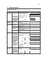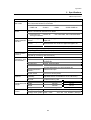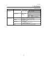
1
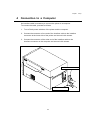
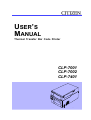
USER’S
MANUAL
Thermal Transfer Bar Code Printer
CLP-7001
CLP-7002
CLP-7401
Before Operation
FCC COMPLIANCE STATEMENT
FOR AMERICAN USERS
This equipment has been tested and found to comply with the limits for a Class A digital
device, pursuant to Part 15 of the FCC Rules. These limits are designed to provide
reasonable protection against harmful interference when the equipment is operated in a
commercial environment. This equipment generates, uses, and can radiate radio frequency
energy and, if not installed and used in accordance with the instruction manual, may cause
harmful interference to radio communications. Operation of this equipment in a residential
area is likely to cause harmful interference in which case the user will be required to correct
the interference at his own expense.
"DESIGNED AND MANUFACTURED TO BE EQUIVALENT TO EUROPEAN
STANDARD FOR ITE, EN60950."
1
Before Operation
EMI COMPLIANCE STATEMENT
FOR CANADIAN USERS
This equipment generates and uses radio frequency energy and if not installed and used
properly, that is, in strict accordance with the manufacturer's instructions, may cause
interference to radio and television reception. This digital apparatus does not exceed the
Class A limits for radio noise emissions from digital apparatus set out in the Radio
Interference Regulations of the Canadian Department of Communications. This equipment
is designed to provide reasonable protection against such interference in a residential
installation. However, there is no guarantee that interference will not occur in a particular
installation. If this equipment does cause interference to radio or television reception, which
can be determined by turning the equipment off and on, the user is encouraged to try to
correct the interference by one or more of the following measures:
・ Reorient or relocate the receiving antenna.
・ Increase the separation between the equipment and receiver.
・ Connect the equipment into an outlet on a circuit different from that to which the
receiver is connected.
・ Consult the dealer or an experienced radio/TV technician for help.
CAUTION:
Use shielded cables to connect this device to computers.
Any changes or modifications not expressly approved by the
grantee of this device could void the user's authority to operate the
equipment.
ETAT DE CONFORMITE EMI A L'USAGE
DES UTILISATEURS CANADIENS
Cet équipment produit et utilise l'énergie à radiofréquences et s'il n'est pas installé et utilisé
correctment, c'esst à dire en accord strict avec les instructions du fabricant, il risque de
provoquer des intérferences avec la réception de la radio et de la télévision.
Le présent appareil numérique n'émet pas de bruite radioélectriques dépassant les limites
applicables aux appareils numériques de la classe A prescrites dans le Réglement sur le
brouillage radioélectrique édicté par le ministère des Communications du Canada.
Cet équipment est conçu pour fournir une protection satisfaisante contre de telles
interférences dans une installation résidentielle. Cependant, il n'y a pas de garantie contre
les interférences avec les réceptions radio ou télévison, provoquées par la mise en et hors
circuit de l'équipment; aussi, il est demandé a l'utilisateur d'essayer de corriger l'interférence
par l'une ou plus des mesures suivantes:
・ Réorienter l'antenne de réception.
・ Installer l'ordinateur autre part, par égard pour le récepteur.
・ Brancher l'ordinateur dans une prise de courant différente de façon à ce que
l'ordinateur et le récepteur soient branchés sur des circuits différents.
2
Before Operation
Important Safety Instructions
1. Read all of these instructions and save them for later reference.
2. Follow all warnings and instructions marked on the product.
3. Unplug this product from the wall outlet before cleaning. Do not use liquid or aerosol cleaners.
Use a damp cloth for cleaning.
4. Do not use this product near water.
5. Do not place this product on an unstable cart, stand or table. The product may fall, causing
serious damage to the product.
6. Slots and openings on the cabinet and the back or bottom are provided for ventilation.
To ensure reliable operation of the product and to protect it from overheating, do not block or
cover these openings. The openings should never be blocked by placing the product on a bed,
sofa, rug or other similar surface. This product should never be placed near or over a radiator
or heat register. This product should not be placed in a built-in installation unless proper
ventilation is provided.
7. This product should be operated from the type of power source indicated on the marking label.
If you are not sure of the type of power available, consult your dealer or local power company.
8. This product is equipped with a three-pronged plug, a plug having a third (grounding) pin. This
plug will only fit into a grounding-type power outlet. This is a safety feature. If you are unable to
insert the plug into the outlet, contact your electrician to replace your obsolete outlet. Do not
defeat the safety purpose of the grounding-type plug.
9. Do not allow anything to rest on the power cord. Do not locate this product where the cord will
be walked on.
10. If an extension cord is used with this product, make sure that the total of the ampere ratings on
the products plugged into the extension cord do not exceed the extension cord ampere rating.
Also, make sure that the total of all products plugged into the wall outlet does not exceed 15
amperes for 120V outlet and 7.5 amperes for 220V-240V outlet.
11. Never push objects of any kind into this product through cabinet slots as they may touch
dangerous voltage points or short out parts that could result in a risk of fire or electric shock.
Never spill liquid of any kind on the product.
12. Except as explained elsewhere in this manual, don't attempt to service this product yourself.
Opening and removing those covers that are marked "Do Not Remove" may expose you to
dangerous voltage points or other risks. Refer all servicing on those compartments to service
personnel.
13. The mains plug on this equipment must be used to disconnect mains power. Please ensure that
the socket outlet is installed near the equipment and shall be easily accessible.
14. Unplug this product from the wall outlet and refer servicing to qualified service personnel under
the following conditions:
A. When the power cord or plug is damaged or frayed.
B. If liquid has been spilled into the product.
C. If the product has been exposed to rain or water.
D. If the product does not operate normally when the operating instructions are followed.
Adjust only those controls that are covered by the operating instructions since improper
adjustment of other controls may result in damage and will often require extensive work
by a qualified technician to restore the product to normal operation.
E. If the product has been dropped or the cabinet has been damaged.
F. If the product exhibits a distinct change in performance, indicating a need for service.
3
Before Operation
Notice
1. Before use, be sure to read this manual. And keep it handy for
reference when needed.
2. The contents of this manual may change without prior notice.
3. Reproduction, transfer, or transmission of the contents of this manual
without prior consent is strictly prohibited.
4. We are not liable for any damage resulting from the use of the
information contained herein, regardless of errors, omissions, or
misprints.
5. We are not liable for any problems resulting from the use of optional
products and consumable supplies other than the designated products
contained herein.
6. Do not handle, disassemble or repair the parts other than those
specified in this manual.
7. We are not liable for any damage caused by user's erroneous use of
the printer and inadequate environment.
8. Data residing in the printer is temporary. Therefore, all data will be lost
if power is lost. We are not liable for any damage or loss of profits
caused by data loss due to failures, repairs, inspections, etc.
9. Please contact us if there are any mistakes or ambiguities within this
manual.
10. If there are missing or incorrectly collated pages in this manual, contact
us to obtain a new manual.
4
Before Operation
SAFETY INSTRUCTIONS
¾ must be strictly observed !
・ご使用前に必ず本書をよくお読み下さい。読み終わった後は大切に保管し、
●
To prevent personal injury or property damage, the following shall be strictly
observed.
●
The degree of possible injury and damage due to incorrect use or improperly
following instructions is described below.
WARNING
Indicates a situation which, if not observed and handled
properly, could result in death or serious injury.
CAUTION
Indicates a situation which, if not observed and handled
properly, could result in injury.
This is a mark to call attention to the reader.
5
Before Operation
WARNING
n Never perform the following. If not avoided, these may cause damage or trouble to the printer
or cause the printer to overheat and release smoke and cause burns or an electrical shock. If
the printer is damaged or is malfunctioning, be sure to turn the power off immediately and
remove the power cord from the outlet, then consult our service personnel.
· Do not jolt or impact to the printer by stepping on, dropping or hitting the printer.
· Do not place the printer in a poorly ventilated area, or shut off the air vent of the printer.
· Do not place the printer where chemical reactions occur, such as in laboratories or where
air is mixed with salt or gas.
· Do not use a power voltage or frequency other than those specified.
· Do not plug/unplug the power cord or attach/detach the interface cable by simply
grabbing the power cord or interface cable. Do not pull or carry the printer when the
tension of the power cord or interface cable is increased.
· Do not drop or put foreign matter such as clips and pins into the printer. This may cause
problems.
· Do not plug the power cord into an outlet with many loads.
· Do not spill drinks such as tea, coffee and juice on the printer or spray insecticide on the
printer. If drink or water is spilled, first be sure to turn the power off and remove the
power cord from the outlet, then consult our service personnel.
· Do not disassemble or modify the printer.
n Discard or safely store the plastic packing bag. This bag should be kept away from children.
If the bag is pulled over a child’s head, it may cause suffocation.
6
Before Operation
General Precautions
1.
Prior to operation, read the safety instructions carefully and observe them.
2.
Do not drop or put foreign matter such as clips and pins into the printer. This may cause
problems.
3.
Be careful when moving or carrying the printer. Dropping the printer may cause injury or
property damage.
4.
Make sure if you open the top cover, it is opened all the way. If only partially open, the
cover could slam shut, possibly causing injury.
5.
When the cover is open, be careful of the corners of the cover. They could cause injury.
6.
Do not open the printer during printing.
7.
When cleaning the surface of the printer case, do not use the cloth that is soaked in
thinner, trichloroethylene, benzine, ketone or similar chemicals.
8.
Do not use the printer where there is a lot of oil, iron particles, or dust.
9.
Do not spill liquids or spray insecticide on the printer.
10.
Do not jolt or impact to the printer by stepping on, dropping or hitting the printer.
11.
Operate the control panel properly. A careless, rough handling may cause problems or
malfunction. Do not use such sharp-edged tool as a ballpoint pen for operation.
12.
Be careful of the edges of the plates so injury or property damage is possible.
13.
If a problem occurs during printing, stop the printer immediately and unplug the power
cord from the outlet.
14.
When printer trouble occurs, do not try to dissemble it. Instead, consult our service
personnel.
7
Before Operation
Precautions When Installing the Printer
1.
Prior to operation, read the safety instructions carefully and observe them.
2.
Do not use or store the printer near fire, excessive moisture, in direct sunlight, near an air
conditioner or heater or other source of unusually high or low temperature or humidity or
excessive dust.
3.
Do not place the printer where chemical reactions occur, such as in a laboratory.
4.
Do not place the printer where air is mixed with salt or gas.
5.
The printer must sit on a firm, level surface where there is ample ventilation. Never allow
the printer's air vent to be blocked by a wall or other object.
6.
Do not put anything on the top of printer.
7.
Do not place the printer near a radio or television, and do not use the same wall outlet for
the printer and radio or television. Radio or television reception could be adversely
affected.
8.
Do not use a power voltage or frequency other than those specified.
9.
Do not put anything on the power cord or step on it.
10.
Do not drag or carry the printer with the power cord or interface cable.
11.
Avoid plugging the power cord into an outlet with many loads.
12.
Do not bundle the power cord when inserting the plug.
13.
Always grip the plug housing, not the cord, to plug/unplug the power cord.
14.
Make certain the power is turned off before connecting/disconnecting the interface cable.
15.
Avoid lengthening the signal cable or connecting it to any noise-producing device. If it is
unavoidable, use the shielded cable or twisted pair for each signal.
16.
Place the printer near the outlet where the power cord can be unplugged easily to shut off
power.
17.
Use the AC outlet that accepts a three-pronged plug. Otherwise, static electricity may be
generated and there will be danger of electric shock.
8
Before Operation
Contents
Before Operation
FCC COMPLIANCE STATEMENT FOR AMERICAN USERS × × × × × × × × × × × × × × × × × × × × 1
××××××××××××××××××× 2
EMI COMPLIANCE STATEMENT FOR CANADIAN USERS
Important Safety Instructions × × × × × × × × × × × × × × × × × × × × × × × × × × × × × × × × × × × × × × × × × × × × × × × 3
Notice × × × × × × × × × × × × × × × × × × × × × × × × × × × × × × × × × × × × × × × × × × × × × × × × × × × × × × × × × × × × × × × × × 4
Safety Instructions × × × × × × × × × × × × × × × × × × × × × × × × × × × × × × × × × × × × × × × × × × × × × × × × × × × × × × × × 5
Warning × × × × × × × × × × × × × × × × × × × × × × × × × × × × × × × × × × × × × × × × × × × × × × × × × × × × × × × ×× × × × × × × × × 6
General Precautions × × × × × × × × × × × × × × × × × × × × × × × × × × × × × × × × × × × × × × × × × × × × × × × × × × × × × × × 7
Precautions When Installing the Printer × × × × × × × × × × × × × × × × × × × × × × × × × × × × × × × × × × × × × × × × 8
Contents × × × × × × × × × × × × × × × × × × × × × × × × × × × × × × × × × × × × × × × × × × × × × × × × × × × × × × × × × × × × × × × × 9
Main Features × × × × × × × × × × × × × × × × × × × × × × × × × × × × × × × × × × × × × × × × × × × × × × × × × × × × × × × × × × 11
Model Description × × × × × × × × × × × × × × × × × × × × × × × × × × × × × × × × × × × × × × × × × × × × × × × × × × × × × × × 12
Chapter 1
1
2
3
4
× × × × × × × × × × × × × × × × × × × × × × × × ×
× × × × × × × × × × × × × × × × × × × × × × × × ×
× × × × × × × × × × × × × × × × × × × × × × × × ×
× × × × × × × × × × × × × × × × × × × × × × × × ×
14
15
18
19
Power On/Off × × × × × × × × × × × × × × × × × × × × × × × × × × × × × × × × × × × × ×
Normal Operating Mode × × × × × × × × × × × × × × × × × × × × × × × × × × × × × ×
Printer Setup Mode × × × × × × × × × × × × × × × × × × × × × × × × × × × × × × × × ×
Self-Test Mode × × × × × × × × × × × × × × × × × × × × × × × × × × × × × × × × × × × ×
System Maintenance Mode × × × × × × × × × × × × × × × × × × × × × × × × × × × × ×
Returning to Factory Setting × × × × × × × × × × × × × × × × × × × × × × × × × × × ×
22
24
25
27
29
32
Confirmation of Carton Contents
Part Names and Functions × × ×
Connection to Power × × × × × × ×
Connection to a Computer × × × ×
Chapter 2
1
2
3
4
5
6
Setup
Printer Operation
9
Before Operation
Contents
Chapter 3
1
2
3
4
5
6
Kinds of Paper × × × × × × × × × × × × × × × × × × × × × × × × × × × × × × × × × × × × × × × × × × × × × × × × × × × 34
Media Handling (When Using Front Sensors) × × × × × × × × × × × × × × × × × × × × × × × × × × 35
Media Handling (When Using Adjustable Sensor) × × × × × × × × × × × × × × × × × × × × × × × 36
Paper Setting × × × × × × × × × × × × × × × × × × × × × × × × × × × × × × × × × × × × × × × × × × × × × × × × × × × × 37
Kinds of Ribbon × × × × × × × × × × × × × × × × × × × × × × × × × × × × × × × × × × × × × × × × × × × × × × × × × × 39
Ribbon Setting × × × × × × × × × × × × × × × × × × × × × × × × × × × × × × × × × × × × × × × × × × × × × × × × × × × 40
Chapter 4
1
2
3
4
5
Printer Adjustments
Using Paper Other Than the Recommended (Head Offset Adjustments) × 44
Using Narrow Paper (Head Pressure Adjustments) × × × × × × × × × × × × × × × 45
Using Narrow Ribbon (Ribbon Tension Adjustments) × × × × × × × × × × × × × 46
Adjustable Sensor (For CLP-7001/7401) × × × × × × × × × × × × × × × × × × × × 47
Cleaning × × × × × × × × × × × × × × × × × × × × × × × × × × × × × × × × × × × × × × × × × 48
Chapter 5
1
2
3
4
5
6
Paper and Ribbon
Troubleshooting
Error Messages × × × × × × × × × × × × × × × × × × × × × × × × × × × × × × × × × × × × 50
Power Troubleshooting × × × × × × × × × × × × × × × × × × × × × × × × × × × × × × × × 54
Paper Feed Troubleshooting × × × × × × × × × × × × × × × × × × × × × × × × × × × × 55
Ribbon Feed Troubleshooting × × × × × × × × × × × × × × × × × × × × × × × × × × × 56
Print Troubleshooting × × × × × × × × × × × × × × × × × × × × × × × × × × × × × × × × 57
Interface Troubleshooting × × × × × × × × × × × × × × × × × × × × × × × × × × × × × × 58
Appendixes
1 Options × × × × × × × × × × × × × × × × × × × × × × × × × × × × × × × × × × × × × × × × × 60
2 Specifications × × × × × × × × × × × × × × × × × × × × × × × × × × × × × × × × × × × × × 62
10
Before Operation
Main Features
High-speed, high-quality printing
This printer adopts both a direct-thermal and thermal-transfer printing system with the line
thermal head and its unique control IC enables high-speed and high-quality printing.
Precision printing for additional value: 400dpi
New technologies such as the newly-developed 400dpi head in the CLP-7401, unique control
IC and optimized driving technology for high-resolution printing are all available on Citizen
label printers creating labels that are crisp, clear, easy-to-read and scan. Also, thanks to the
additional front (label) sensors, an amazingly high level of accuracy can be achieved; small
sized labels, miniature bar codes and small fonts are produced on demand and in the correct
position leading to a reduction in cost, lead time and stock holding.
Powerful control language
A powerful yet simple to use control language is standard to all of Citizen’s label printers
allowing easy design of labels and bar codes. Alternatively, Citizen provides printer drivers for
popular operating systems such as Windows™.
Easy operation
Thanks to the clam-shell mechanism, labels, media and ribbons are loaded easily and
maintenance such as head cleaning is carried out smoothly.
Parallel and serial ports as the standard
The parallel port (Centronics) in addition to the serial port is provided as the standard to
enable high-speed data transmitting and industry compatible connectivity.
Adjustable media sensor
The moveable media detection sensor, standard on the CLP-7001 and CLP-7401 allows
irregularly cut labels and tags to be used with ease. The sensors can also detect black
registration marks that are not at the edge of the media.
Trademark Acknowledgement:
Windows: Microsoft Corporation
11
Before Operation
12
Before Operation
Model Description
This manual is prepared for the three models, CLP-7001, CLP-7002 and CLP-7401.
The main different points on the specifications among the three are shown below.
Model
Print resolution
Printing speed
Adjustable senso
r
CLP-7001
203dpi
2-7 IPS
Standard
CLP-7002
203dpi
2-6 IPS
Optional
CLP-7401
400dpi
1-4 IPS
Standard
13
Chapter 1 Setup
Chapter 1
Setup
1
Confirmation of Carton Contents
2
Part Names and Functions
3
Connection to Power
4
Connection to a Computer
13
Chapter 1 Setup
1
Confirmation of Carton Contents
Check that the following accessories are included with the printer in the carton.
Power cord
Paper core
Roll holder
Roll guide
Ink ribbon
User’s manual
Cleaning pen
Printer
Label paper
* The empty carton and packing materials should be stored for future shipping of the printer.
CAUTION
· Be careful when moving or carrying the printer and when taking the printer out of the
carton. The printer may cause injury or property damage if dropped. Be sure to grip
the printer housing tightly when taking it out of the carton. Do not grip the printer by
the foam packing material which may break, causing the printer to drop.
14
Chapter 1 Setup
2
Part Names and Functions
Front view
8
1
3
12
6
4
5
7
9
11
10
2
① Cover
Opens to allow loading of the paper and
ribbon.
⑧ Open lever
To swing the print head out of the way
when loading the paper or cleaning the
print head. (See Chapter 3.)
② Control panel
To set the printer settings. (See Chapter
2.)
⑨ Open guide
Holds down the paper. The movable
sensor inside this (when the model is an
adjustable sensor type) detects the paper
position. (See Chapter 3.)
③ Ribbon holder
To attach the ribbon. (See Chapter 3.)
④ Ribbon winder
To wind the ribbon after print.
(See Chapter 3.)
⑩ Open guide lever
Pressing this opens the open guide to
replace the paper. (See Chapter 3.)
⑪ Front sensors
Detect the label and tag paper position.
(See Chapter 3.)
⑤ Roll holder
Holds the roll of paper.
⑥ Roll guide
Guides the roll of paper. This is adjusted
according to the width of the paper. (See
Chapter 3.)
⑫ Offset verification window
Allows you to check the optimum position
of the print head. (See Chapter 4.)
⑦ Paper holder
Holds the roll holder. (See Chapter 3.)
15
Chapter 1 Setup
2
Part Names and Functions
Rear view
3
2
5
4
1
① Serial interface connector
To connect the serial interface cable.
④ Power inlet
To connect the power cord.
② Parallel interface connector
To connect the parallel interface cable.
⑤ PCMCIA memory card cover
To protect the PCMCIA memory card
from exposure to dust and foreign
matter. To install a PCMCIA memory
card, first unhook this cover, then slide it
out. (See Appendixes.)
③ Power switch
To turn on or off the power. (See Chapter
2.)
CAUTION
· When opening the cover, open it all the way. If only part way open, the cover could
slam shut, possibly causing injury.
· Be careful of the edge of the cover when the cover is opened. It may cause injury or
property damage.
· Be careful of the edges of the plates so injury or property damage is possible.
16
Chapter 1 Setup
2
Part Names and Functions
Control panel
1
6
2
7
8
5
4
3
⑤ Stop key
Stops the printer operating.
① LCD
Displays the current printer status,
configuration settings, or an error message.
⑥ Paper gap adjustment control
To adjust the paper gap sensor sensitivity.
② LEDs
One LED is the power indicator and the
other is the error indicator.
⑦ Black line adjustment control
To adjust the black line sensor sensitivity.
③ Pause key
Temporarily pauses printing.
⑧ LCD contrast adjustment control
To adjust the LCD contrast.
④ Feed key
Feeds the paper.
17
Chapter 1 Setup
3
Connection to Power
1. Check that the power switch on the printer is turned OFF.
2. Connect the connector of the power cord to the power inlet on the printe
r.
3. Insert the plug of the power cord in the AC outlet.
AC outlet
Power switch
Power inlet
CAUTION
· Use an AC outlet that accepts a three-pronged plug. Otherwise, static electricity may
be generated and there will be danger of electric shock.
18
Chapter 1 Setup
4
Connection to a Computer
An interface cable is necessary to connect the printer to a computer.
To connect the cable, proceed as follows.
1. Turn off both power switches of the printer and the computer.
2. Connect the connector of one end of the interface cable to the interface
connector at the lower side of the printer and secure it with screws.
3. Connect the connector of the other end of the interface cable to the
interface connector on the computer and secure it with screws.
Parallel interface cable
Serial interface cable
19
Chapter 1 Setup
20
Chapter 2 Printer Operation
Chapter 2
Printer Operation
1
Power On/Off
2
Normal Operating Mode
3
Printer Setup Mode
4
Self-Test Mode
5
System Maintenance Mode
6
Returning to Factory Setting
21
Chapter 2 Printer Operation
1
Power On/Off
Turning on the power
1. Turn on the power switch on the back of the printer.
2. The green LED power indicator goes on. Check that the LCD screen displays ‘ON LINE.’
When
When displaying an error message
operating
ON LINE
HeadOpe
When displaying no message
Contrast
adjustment
control
22
Turn the LCD
contrast
adjustment control
with a small
Phillips head
screwdriver.
Chapter 2 Printer Operation
1
Power
On/Off
Turning off the power
1. Turn off the power switch on the back of the printer.
2. The green LED power indicator goes off and any message on the LCD screen disappears.
23
Chapter 2 Printer Operation
2
Normal Operating Mode
When the power is turned on, the printer enters normal operating mode. The control keys
function as follows:
ON LINE
Stop key (STOP)
With this key, the operator can stop and cancel the current
print job. Pressing the Stop key during printing stops the
printing immediately. Pressing the Stop key again cancels the
print job.
Feed key (FEED)
Advance to the top of the next label. When using continuous paper,
make sure the Sensor selection is set to ContinuP or a Paper error will
result.
Pause key (PAUSE)
Temporarily pauses printing. ‘Pause’ is displayed on the LCD screen. If pressed
during printing, printing will stop after the current label is printed. Press the Pause
key again to resume printing.
24
Chapter 2 Printer Operation
3
Printer Setup Mode
In this mode, the print mode, optional equipment ON/OFF and sensor selections are
set up. Control keys function in the following. The printer configuration settings are stored in
memory so they are maintained even after the power is turned off.
ON LINE
ON LINE
Returns to normal
operating mode.
Pressing these keys
simultaneously places the
printer into printer setup mode.
Selects the mode item.
Selects the mode.
Example
Changing the paper gap sensor to the black line sensor
1. First check the printer goes ON LINE, then press and hold the Pause key and then press the
Feed key and release both keys.
Transfer
ON LINE
2. Change the print mode (direct-thermal or thermal transfer printing) to the sensor selection with
the Pause key.
Edge
Transfer
25
Chapter 2 Printer Operation
3 Printer Setup Mode
3. Change the paper gap sensor to the black line sensor with the Feed key.
Edge
Reflect
4. Return to normal operating mode with the Stop key.
Reflect
ON LINE
Indication
Mode item
Printing mode
Transfer
DirectTM
Peeling sensor
PeelOFF
PeelON
Auto-cutter
CutOFF
CutON
Tearing
TearOFF
TearON
Sensor selection
Edge
Interpreter ※
INTP STD
Reflect
ContinuP
INTP RST
※ Normally ‘INTP STD’ (interpreter standard) is used. See the Command Reference
for details.
26
Chapter 2 Printer Operation
4
Self-Test Mode
In this mode, self-test printing is performed. With this test printing, you can check the current
printer configuration settings and print quality. After loading the paper and ribbon, operate the
printer as follows:
1. Press and hold the Feed key while turning the printer on.
When label paper is used: Hold down the Feed key for two (2) seconds and the printer will feed
the paper and print samples 1 and 2 and stop.
When continuous paper is used: Hold down the Feed key for four (4) seconds and the printer will
feed the paper and print samples 1 and 2 and stop.
TestPrin
Sample 1
ROM version No.
Date and time
ROM checksum
RAM check
Communication setting
Print mode
Media sensor voltage
Head rank and resistance value
Peeling sensor
Auto-cutter
Ribbon sensor
Total travel distance
27
Chapter 2 Printer Operation
4
Check the following items in the self-test mode.
Check item
Cause
Dot missing
Head disconnected
Dust adhered
Totally blurred
Head offset changed in position
Printing energy low
Partially blurred
Head pressure unbalanced
Ribbon wrinkling and
slipping
Ribbon tension improper
Self-Test Mode
Remedy
Replace head
Clean head(→Section 5 Chapter 4)
Adjust head offset (→Section 1 Chapter
4)
Adjust printing energy
(→Command Reference)
Adjust head pressure
(→Section 2 Chapter 4)
Adjust ribbon tension
(→Section 3 Chapter 4)
Sample 2
203 dpi
Sample 2
400 dpi
2. After self-test printing, the printer enters data dump mode.
The communication contents can be checked by printing the communication data in ASCII code.
28
Chapter 2 Printer Operation
3. Return to normal operating mode after turning off the power switch.
29
Chapter 2 Printer Operation
5
System Maintenance Mode
In this mode, the communication, adjustable sensor ON/OFF and sensor voltage
selections are set up. The printer configuration settings are stored in memory so they are
maintained even after the power is turned off. Control keys function as follows:
ON LINE
Return to normal
operating mode.
Pressing all these keys
simultaneously places the printer
into system maintenance mode.
Selects the mode item.
Selects the mode.
Example
Setting the black line sensor voltage
1. First turn off the power switch, then press and hold down the Pause, Feed and Stop keys
simultaneously while turning on the power switch.
9600bps
2. Change the baud rate to the sensor voltage setting with the Pause key.
9600bps
PE.*.**V
30
Chapter 2 Printer Operation
5
System Maintenance Mode
3. Change the paper gap sensor voltage to the black line sensor voltage with the Feed key.
PE.*.**V
BL.*.**V
4. Return to normal operating mode with the Stop key.
ON LINE
BL.*.**V
Indication
Mode item
Baud rate
9600bps
Data length
8bits
7bits
NativeON
NativeOF
CmndSTD
CmndAS4
Adjustable sensor ※3
AJSensOF
AJSensON
Voltage setting ※4
PE *.**V
BL *.**V
Native ※1
Command code ※2
19200bps
31
Chapter 2 Printer Operation
5
System Maintenance Mode
※1 Native
Normally ‘NativeON’ is used. See the Command Reference for details.
※2 Feed amount
See the Command Reference for details.
※3 Command code
Normally ‘CmndSTD’ is used. See the Command Reference for details.
※4 For adjustable sensor, the voltage setting must be done each time ‘AJSensOF’ is
changed to ‘AJSensON, and vice versa.
※5 Voltage setting
In the voltage setting, adjust the paper gap and black line adjustment controls
so that the voltages of both ‘PE’ and ‘BL’ displayed on the LCD screen can
read 3.0V to 3.3V.
1. Set the liner (glassine paper) only that has been removed from the label. (For the black line
paper, position the black line so that it does not come to the paper sensor.)
2. Set each level to 3.0V to 3.3V with the controls.
Paper gap sensor adjustment control
Black line sensor adjustment control
32
Chapter 2 Printer Operation
6
Returning to Factory Setting
To return the configuration already set in the printer setup mode or system maintenance mode to
the factory setting, proceed as follows:
Turn off the power switch. Press and hold the Pause, Feed and Stop keys simultaneously while
turning on the power switch, and further continue holding down those keys.
Press and hold those keys
simultaneously while turning on
the power switch
S Mainte
S/I Init
You hear a ‘Pi’ sound. Further continue
holding down those keys
When you again hear a ‘Pi’ sound,
the operation is completed
Fac tory se tting
Printer setup mode
System maintenance mode
Mode item
Indication
Mode item
Indication
Printing mode
Transfer
Baud rate
9600bps
Peeling sensor
PeelOFF
Data length
8bits
Auto-cutter
CutOFF
Native
NativeON
Tearing
TearOFF
Feed amount
fVirtual
Sensor selection
Edge
Command code
CmndSTD
Interpreter
INTP STD
Adjustable sensor
AJSensOF
Voltage setting
PE *.**V
¾
¾
33
Chapter 3 Paper and Ribbon
Chapter 3
Paper and Ribbon
1
Kinds of Paper
2
Media Handling
(When Using Front Sensors)
3
Media Handling
(When Using Adjustable
Sensor)
4
Paper Setting
5
Kinds of Ribbon
6
Ribbon Setting
33
Chapter 3 Paper and Ribbon
1
Kinds of Paper
Item
Specification
Kinds of
paper
· Thermal-transfer
paper
· Direct-thermal paper
The printer is capable of printing on direct-thermal
or thermal-transfer paper.
The paper must be high-quality. Otherwise, good
print quality and extended print head life cannot be
guaranteed.
Type of
paper
· Label paper
(continuous, die-cut,
fanfold)
· Tag paper
· Ticket
Both in-wound and out-wound paper rolls may be
used.
Size of
paper
Paper width
Paper thickness
25.4-118 mm
1-4.65 in
0.0635-0.254 mm
0.0025-0.01 in
203 mm
8 in
38-76 mm
1.5-3 in
Max. outer diameter of
roll paper
Paper core inner
diameter
34
Chapter 3 Paper and Ribbon
2 Media Handling
(When Using Front Sensors)
The front sensors consist of the transparent-type and reflective-type photosensors and the
position of a label or tag is detected as follows:
Transparent-type photosensor: Detects paper gap between labels and tag paper notch.
Reflective-type photosensor:
Detects black line.
Note: Check that the adjustable sensor is set to ‘AJSensOF.’ (See Chapter 2.)
· Specification of paper
For dimensions of paper gap between labels, tag paper (label paper) notch and black line,
see figure.
Minimum value mm
A
(in)
Maximum value mm
(in)
Label width
7.62
(0.3)
118.00
(4.65)
25.40
(1.0)
118.00
(4.65)
B
Liner width
C
Label left edge position
0
D
Label paper gap length
2.54
(0.10)
E
Label length
2.54
(0.10)
2.54
(0.10)
2539.00
(99.96)
2539.00
(99.96)
F
5.08
Label pitch
(0.20)
2539.00
(99.96)
G
0.06
Liner thickness
(0.0025)
0.125
(0.0049)
H
0.06
Paper thickness
(0.0025)
0.25
(0.
01)
I
8.3
Notch right end position
(0.3
2)
J
11
(0.4
3)
0
Notch left end position
4.7
(0.19)
K
2.54
Notch length
(0.10)
17.80
(0.
70)
L
Black line right end position
M
Black line left end position
15.00
(0.59)
―
0
1.5
(0.
06)
N
3.18(0.125)
Black line width
17.80
70)
Note:
· Paper having both label paper gap and black line should use the paper-gap sensor.
· Fanfold should use the paper-gap sensor.
Size of paper
Label paper
Continuous paper
Notch detection
Label
Black line detection
Printable
area
Label
Black line
OD value: 1.5 or
more
Carbon black ink
Label
35
(0.
Chapter 3 Paper and Ribbon
Using paper gap
adjustment sensor
Using paper gap
adjustment sensor
Using black line
adjustment sensor
Direction of paper feed
2.5mm
Left margin
104.0mm
Printable area
(11.5mm)
Right margin
3 Media Handling (When Using Adjustable Sensor)
The adjustable sensor is the standard for CLP-7001 and CLP-7401 but it is the optional for CLP7002.
Check that the adjustable sensor is set to ‘AJSensON.’ (See Chapter 2.)
Minimum value mm (in)
Maximum value mm (in)
A
Label width
25.40
(1.0)
118.00
(4.65)
B
Liner width
25.40
(1.0)
118.00
(4.65)
C
Label left edge position
2.54
(0.10)
D
Label paper gap length
E
0
2.54
(0.10)
2539.00 (99.96)
Label length
12.70
(0.50)
2539.00
F
Label pitch
12.70
(0.50)
2539.00
(99.96)
G
Liner thickness
0.06
(0.0025)
H
Paper thickness
0.06
(0.0025)
0.25
(0.01)
I
Notch right end position
3.6
(0.14)
60.8
(2.39)
J
Notch left end position
57.2
(2.25)
K
Notch length
2.54
(0.10)
17.80
(0.70)
L
Black line right end positio
15.00
(0.59)
66.5
(2.62)
(99.96)
0
0.125
(0.0049)
n
M
Black line left end position
N
Black line width
Note:
0
3.18
(0.125)
51.5
(2.02)
17.80
(0.70)
· Paper having both label paper gap and black line should use the paper-gap sensor.
· Fanfold should use the paper-gap sensor.
Size of paper
Label paper
Continuous paper
Label
Printable
area
Label
36
Notch detection
Black line detection
Chapter 3 Paper and Ribbon
Black line
OD value: 1.5 or
more
Carbon black ink
Label
Using paper gap
adjustment sensor
Using paper gap
adjustment sensor
Using black line
adjustment sensor
Direction of paper feed
Printable area
2.5mm
Left margin
4
104.0mm
Printable area
(11.5mm)
Right margin
Paper Setting
The printer is designed for easy loading of paper. Open the printer cover and set the paper as
follows:
1. Push down the open lever to open the print head.
2. Push down the open guide lever to lift the open guide up.
3. Attach the roll guide to the roll holder and insert this in the hole of the roll paper. Set the
roll holder with the roll paper and guide on the paper holder and push this against the
left-side wall so that the roll paper is positioned in its deepest position.
37
Chapter 3 Paper and Ribbon
CAUTION
Be careful of the edges of the plates so injury or property damage is possible.
4
Paper Setting
4. ① Set the paper flush against the fixed paper guide on the left side.
② Guide the paper positively with the movable paper guide.
③ Align the paper top left edge with the notch of the tearing plate.
2
Movable paper guide
1
3
Notch of tearing plate
5.
Fixed paper guide
Slightly hold down the paper so as not to be skew and push down the open guide for
closing.
38
Chapter 3 Paper and Ribbon
6.
Push down the green tab on the front side until it clicks to securely close the printer
mechanism.
Note: Make certain the green part is pressed
properly. Otherwise, the printer mechanism
may fail to close.
7.
Close the printer cover.
8.
Turn on the power to the printer. The LCD screen on the control panel will display ‘ON
LINE.’ Press the Feed key. The paper will advance to the next label and stop.
39
Chapter 3 Paper and Ribbon
5
Kinds of Ribbon
Item
Kinds of
ribbon
Specification
This printer uses a solid ink ribbon.
・Wax
Multipurpose ribbon.
・Wax resin
Multipurpose, high-quality ribbon.
・Resin
Special ribbon with weather resistance. When using
this type, set the print speed slower and the printing
energy greater.
Type of
ribbon
Both in-wound and out-wound ribbons can be used.
Size of
ribbon
With a single roll of ribbon (360 m), about two rolls of paper with outer diameter of
203 mm (8 in) can be used for printing.
・Ribbon width
※ Recommended ribbon width:
±10% of width of paper used
25.4-114 mm
・Max. length
360 m
・Max. outer diameter
・ Paper core inner
diameter
1-4.5 in
1,181 feet
74 mm
2.91 in
25.4±0.254 mm
1±0.01 in
40
Chapter 3 Paper and Ribbon
6
Ribbon Setting
This printer is designed for easy loading of ribbon. Open the printer cover and set the ribbon
as follows:
1. Push down the open lever to open the print head.
2. Insert the ribbon shaft in the hole of the ribbon until it is in its deepest position.
3. Set the ribbon holder on the transfer frame.
1
2
4.
Insert the ribbon shaft in the paper core until it is in its deepest position. Then set this on
the front side of the transfer frame.
1
2
CAUTION
Be careful of the edges of the plates so injury or property damage is possible.
41
Chapter 3 Paper and Ribbon
6
Ribbon Setting
5. Turn the knob on the front side in the direction of arrow to remove the slack of the ribbon.
6.
Push down the green part on the front side until it clicks to securely close the printer
mechanism.
Note: Make certain the green part is pressed properly. Otherwise, the printer mechanism
may fail to close.
7.
Close the printer cover.
8.
Turn on the power to the printer. The LCD screen on the control panel will display ‘ON
LINE.’ Press the Feed key. The paper will advance to the next label and stop.
42
Chapter 3 Paper and Ribbon
43
Chapter 4 Printer Adjustment
Chapter 4
Printer Adjustments
1
Using Paper Other Than
the Recommended (Head Offset
Adjustments)
2
Using Narrow Paper
(Head Pressure Adjustments)
3
Using Narrow Ribbon
(Ribbon Tension Adjustments)
4
Adjustable Sensor
(For CLP-7001/7401)
5
Cleaning
43
Chapter 4 Printer Adjustment
1
Using Paper Other Than the Recommended
(Head Offset Adjustments)
The printer has already been factory-set to the proper print quality when using the
recommended label paper. If the print quality is inferior because of the different type of
paper, adjust the head offset as follows:
(a) When using standard label,
slick, craft or thermal
paper
① Peeping through the
offset verification window,
adjust the head offset so
that it comes to the
Offset adjustment screw (M3)
center line (middle of the
three lines) by turning the
offset adjustment screw
Offset verification window
with a screwdriver.
Turn the offset
adjustment screw two or
three turns
counterclockwise with a
screwdriver. (Factory set:
Two turns.)
The relationship between the offset verification window and the
print head heating element is shown below:
② Make fine adjustments,
checking the self-test print.
a) Print head position for label
Offset adjustment screw
Offset verification window
a
Heating
element
b) Print head position for tag
Offset adjustment
screw
Heating
element
Offset verification
window
b
(b)
When using thick paper
(tag or other paper)
① Peeping through the
offset verification
window, adjust the head
offset so that it comes to
the center line (middle of
the three lines) by
turning the offset
adjustment screw with a
screwdriver.
② Turn the offset
adjustment screw two to
four turns clockwise with
a screwdriver.
③ Make fine adjustments,
44
Chapter 4 Printer Adjustment
checking the self-test
print.
45
Chapter 4 Printer Adjustment
2
Using Narrow Paper (Head Pressure Adjustments)
The printer has already been factory-set to the paper width of 112 mm (4.4 in). When you use
narrow paper, adjust the head pressure as follows:
1.
Looking at the check window on the upper frame, align the mark (the left edge of white
plastic) with the width of the paper. (The print head is closed.)
2.
Make fine adjustments, checking the print.
(a) When the print on right side is too light:
Move the mark to the right by turning the head pressure adjustment screw clockwise.
(b) When the print on the left side is too light:
Move the mark to the left by turning the head pressure adjustment screw
counterclockwise.
※
These adjustments are useful for preventing ribbon wrinkle or paper skew. For more
details, consult our service personnel.
Check window
Width of paper
25.4 mm
1 in
50.8 mm
2 in
76.2 mm
3 in
101.6 mm
4 in
When ribbon wrinkles or paper
skews with paper width of 4 in or
more
Factory setting
46
Chapter 4 Printer Adjustment
3
Using Narrow Ribbon (Ribbon Tension Adjustments)
If ribbon slips or wrinkles during printing, adjust the ribbon tension.
The printer has already been factory-set to the ribbon width of 114 mm (4.5 in). When you use
a different ribbon, adjust the ribbon tension as follows:
1.
Hold the ribbon roll by one hand on the side of the knob you operate so that it does not
turn.
2.
Slightly push the knob to the ribbon roll and turn it until the stopper comes to the desired
position.
3.
Gradually release the knob so that the stopper fits in the groove on the side of the knob.
Set values to each ribbon width:
*: Factory settin
g
Knob on ribbon
Knob on ribbon
Ribbon width
winding section
feeding section
5
5
Adjustments when ribbon slipping occurs
4
4
25.4 mm (1 in) 50.8 mm (2 in)
3
3
76.2 mm (3 in)
2
2
101.6 mm (4 in)
1*
1*
Adjustments when ribbon wrinkle occurs.
4.
Perform printing and check for ribbon wrinkle or slipping. If it s occurs, adjust it according
to the following procedure:
(a) Ribbon wrinkles: Increase the tension on the ribbon winding section.
(b) Ribbon slips:
Decrease the tension on the ribbon feeding section.
If it is not resolved even when the tension on the ribbon
feeding section is set to 5 (Mild), increase the tension on
the ribbon winding section.
※
If ribbon problems are not resolved, consult our service personnel.
Ribbon feeding section
Ribbon winding section
Variable knob
Mild
Strong
Strong
Mild
47
Chapter 4 Printer Adjustment
4
Adjustable Sensor (For CLP-7001/7401)
※ The adjustable sensor is the optional for CLP-7002.
Adjustable knob
Upper guide rail
Mark (yellow)
Operating procedure:
1.
Move the adjustable sensor to your required detection position by tuning the adjustable
knob. Measure your detection position beforehand. To set the detection position, align
the scale marking on top of the upper guide rail with the sensor position mark (yellow)
on the upper of the sensor. The movable range of the adjustable sensor is shown
below.
2.
Set the liner and close the upper guide rail and set voltage to 3V.
※
For voltage setting, see Section 5: System Maintenance Mode, Chapter 2.
Left edge of paper
0 mm
118 mm (max. paper width)
59 mm (sensor usable range)
Adjustable sensor
movable range
48
Chapter 4 Printer Adjustment
49
Chapter 4 Printer Adjustment
5
Cleaning
Wipe off any foreign matter such as ribbon or paper residue, dust and adhesive substance
stuck to the thermal head, ribbon guide roller, platen etc with the accessory cleaning pen or
a soft cloth soaked in ethyl alcohol. Cleaning of the thermal head is essential to guarantee
print quality and extend print head life especially when printing on the direct-thermal paper
for long periods.
Caution:
Do not use solvent other than ethyl alcohol such as benzene and thinner that will
dissolve plastic.
Ribbon guide roller
Ribbon guide roller
Thermal head
Platen
50
Chapter 5 Troubleshooting
Chapter 5
Troubleshooting
1
Error Messages
2
Power Troubleshooting
3
Paper Feed Troubleshooting
4
Ribbon Feed Troubleshooting
5
Print Troubleshooting
6
Interface Troubleshooting
49
Chapter 5 Troubleshooting
1
Error Messages
When there is a problem with the printer:
- A buzzer sounds.
- The error indicator lights up.
- An error message is displayed on the LCD screen.
Error descriptions and corrective actions are shown below.
1
Error descriptions and indications
Description
Battery dead (for clock and backup RAM)
Head temperature low
PCB temperature low
Head resistance value abnormal (error contents and
head information repeatedly displayed)
Rank:
Rank of head resistance value
Average:
Average of resistance values (A/D
reading value in decimal system)
Maximum: Max. resistance value
Minimum: Min. resistance value
Communication error (receive buffer overrun)
Communication error (parity, framing)
Communication error (transmit buffer overflow)
Pause key pressed
Pause command reception (remote control)
Head overheat
Stop key pressed
Stop command reception (remote control)
Mechanism head open
Paper end (paper out)
Paper out (paper position cannot be detected) (error
contents and sensor information repeatedly
displayed)
M command: Sets length for detection miss
checking with system command M
Maximum: Max. value of sensor reading voltage
Minimum: Min. value of sensor reading voltage
Ribbon end
PCB overheat
(PCB or sensor abnormal)
Fan stop
Option board abnormal
Auto-cutter abnormal (such as poor engagement)
ROM checksum error
RAM check error
Indication
Battery
ColdHead
Cold PCB
LED
Lights
Lights
Lights
Lights
Sounds
Sounds
Sounds
Sounds
Buzzer
long
long
long
long
Lights
Lights
Blinks
Sounds long
Sounds long
Sounds short 3 times
--Blinks
--Sounds short 3 times
--Lights
Lights
Lights
Sounds
-Sounds
Sounds
Sounds
RibonOut
OverHeat
Lights
Lights
Sounds short 3 times
Sounds short 3 times
Fan stop
OP Err
Cut Err
ROM Err
RAM Err
Blinks
Lights
Lights
Lights
Lights
Sounds short 3 times
Sounds short 3 times
Sounds short 3 times
Sounds long
Sounds long
Head Err
Rank ***
Ave.***
Max.***
Min.***
OverFlow
S/I Err
HostBusy
T.D.Full
Pause
Pause
OverHeat
Cooling
Stop
Cancel
HeadOpen
PaperEnd
PaperErr
short 3 times
short 3 times
short 3 times
short 3 times
M CMMD
Max*.**V
Min*.**V
50
Chapter 5 Troubleshooting
1
Error
Messages
2
Error indications and corrective actions
Indication
Description
Corrective actions
Battery
Battery dead
Automatically returned after displaying the error
for a certain time.
Change the lithium battery (CR2032).
Note: Contact our service personnel to replace
the battery.
If the battery runs down, the realtime clock will
stop and the contents of the memory switch will
be lost.
ColdHead
Head temperature low
Automatically returned after displaying the error
for a certain time.
Raise the temperature around the printer.
Print density becomes low and print quality
becomes inferior when the head
temperature is low.
Cold PCB
PCB temperature low
Automatically returned after displaying the error
for a certain time.
Raise the temperature around the printer.
Print density becomes low and print quality
becomes inferior when the head temperature
is low.
Head Err
Head resistance value
abnormal
Check the contents and clear with the Stop
key.
Replace the print head.
Print quality is affected at the section where the
head resistance value is abnormal.
OverFlow
S/I Err
Communication error
(receive buffer
overrun)
Check the contents and clear with the Stop
key.
Communication error
(parity, framing)
Check the contents and clear with the Stop
key.
Correct the communication control system or
communication cable abnormalities.
Correct the communication parameter or
communication cable abnormalities.
HostBusy
T.D.Full
Communication error
(transmit buffer
overflow)
Automatically returned if the computer receives
data and the buffer becomes empty.
Pause
Pause key pressed
Pressing the Pause key again resumes
printing.
If the Stop key is pressed, the stored printing
contents are discarded and ‘ON LINE’ turns on.
51
Chapter 5 Troubleshooting
Pause
Pause command
reception
(communication
control)
Same as above.
1
Error
Messages
Indication
Description
Corrective actions
OverHeat
Cooling
Head overheat
Wait until the head temperature goes down.
When the temperature becomes low, the
remaining printing resumes.
Stop
Stop key pressed
Enters a pause after displaying ‘Stop’ by the
Stop command.
If the Pause key is pressed, the printing will
resume.
If the Stop key is pressed again, the stored
printing contents are discarded and ‘ON LINE’
turns on.
Cancel
Stop command
reception
(communication
control)
Displays ‘Stop’ by the stop command,
discards the remaining printing contents, and
enters pause.
HeadOpen
Mechanism head
open
Close the mechanism head.
PaperEnd
Paper end (paper
out)
Install the paper.
PaperErr
Paper out (paper
position cannot be
detected)
Check the contents and clear with the Stop
key.
If the Pause key is pressed, ‘ON LINE’ will turn
on.
Correct the faulty setting of the paper
detection (paper gap, black line, continuous
paper).
Correct the faulty parameter for paper (max.
length, continuous paper).
Adjust the sensor or change to the paper that
can accept the paper position detection.
Specify the detection miss checking length
with the M command.
When the paper position cannot be detected
during paper feeding by the specified length, it
is judged error. Generally specify the length
about three times the label length.
In case of continuous paper, specify the label
length with the C command.
Difference between the maximum and
52
Chapter 5 Troubleshooting
minimum values of the sensor reading voltage
must be 0.8 V or more.
Sensor adjustments and check of paper
characteristic (voltage checking) can be
performed with the Maintenance mode.
1
Error
Messages
Indication
RibonOut
Description
Ribbon end
Corrective actions
Check the contents and clear with the Stop
key.
Install the ribbon.
Check that ribbon winds properly.
Correct the faulty setting of the print mode
(direct-thermal or thermal-transfer).
OverHeat
PCB overheat
Turn off the power and reset the printer. If this
recurs, contact our service personnel.
Fan stop
Fan stops
Check for fan stop caused by the problems
such as foreign matter in the air vent.
Automatically returned if the fan turns again.
If disassembling is needed to remove foreign
matter or the problem cannot be resolved,
contact our service personnel.
OP Err
Option board
abnormal
Turn off the power and reset the printer. If this
recurs, contact our service personnel.
Cut Err
Auto-cutter abnormal
(such as poor
engagement)
Check the contents and clear with the Stop
key.
If this cannot be cleared, turn off the power
and remove foreign matter from the autocutter.
If this recurs, contact our service personnel.
ROM Err
ROM checksum error
Turn off the power and reset the printer. If this
recurs, contact our service personnel.
RAM Err
RAM check error
Turn off the power and reset the printer. If this
recurs, contact our service personnel.
--
System error (such
as timer or CPU
malfunction)
First protect the system, then turn off the
power and reset the printer. If this recurs,
contact our service personnel.
53
Chapter 5 Troubleshooting
54
Chapter 5 Troubleshooting
2
Power Troubleshooting
Problem
No power even
with power switch
turned ON.
Cause and remedy
• Power cord is not
properly connected to
the outlet.
®
Turn off the power switch and
reconnect the power cord to the
outlet properly.
• Power cord is not
properly connected to
the power inlet.
®
Turn off the power switch and
reconnect the power cord to the
power inlet properly.
• Input voltage is not
correct; input voltage is
greater or less than the
rated voltage.
®
Set input voltage within the rated
voltage (puncture voltage may
occur. Contact our service
personnel).
• Correct RS-232C cable
is not used.
®
Turn off the power switch and
unplug the interface cable.
Check that power is provided by
turning on the power switch and
use the correct RS-232C cable.
55
Chapter 5 Troubleshooting
3
Paper Feed Troubleshooting
Problem
Paper doesn't
feed.
Paper skew.
Paper doesn't
align with the print
position.
Cause and remedy
・ Wrong paper path.
®
・ Mechanism head is
open.
Use correct path. (See Chapter
3)
®
Close the mechanism head.
・ Edge of paper is not in
contact with the paper
guide.
®
Slightly push the paper guide to
the edge of the paper.
(See Chapter 3)
・ Roll guide is not in
contact with the roll
paper.
®
Slightly push the roll guide to the
roll paper. (See Chapter 3)
・ Head pressure is not
correct.
®
Adjust it with the offset
adjustment screw according to
the width of the paper. (See
Chapter 4)
・ Setting mode is not
correct.
®
Check whether the setting mode
is for paper gap or black line
sensor and if it is not, change it.
(See Chapter 2)
・ Paper gap (black line)
sensor adjustment
failure.
®
Adjust the voltage of the paper
gap or black line sensor from the
voltage setting in the system
maintenance mode.
(See Chapter 2)
®
If the contents of the transfer data
are incorrect, set them properly
again.
・ Transfer data is abnormal.
56
Chapter 5 Troubleshooting
4
Ribbon Feed Troubleshooting
Problem
Ribbon doesn't
wind.
Ribbon wrinkles.
Cause and remedy
・ Wrong ribbon path.
®
・ Ribbon winding direction
is reversed.
Use correct path. (See Chapter
3)
®
Set it properly. (See Chapter 3)
・ Ribbon holder and
winder tension is not
correct.
®
Set it properly. (See Chapter 3)
・ Ribbon and paper are
not proper.
®
Contact our service personnel.
・ Ribbon holder and
winder tension is not
correct.
®
Set it properly.
®
Correct the parameter of the Hnn
command in the printing contents
definition mode.
(See Appendixes)
・ Angle of ribbon guide bar
is not correct.
®
Contact our service personnel to
adjust the ribbon guide bar.
・ Head pressure doesn’t
match paper width.
®
If not, the ribbon may wrinkle.
Adjust head pressure with the
adjustment screw.
(See Chapter 4)
®
Contact our service personnel.
・ Print density (heating
factor) is not correct.
・ Ribbon and paper are
not proper.
57
Chapter 5 Troubleshooting
5
Print Troubleshooting
Problem
Printing doesn't
start.
Cause and remedy
・ Power to the printer is not
turned on.
®
・ Printer is not properly
connected to the
computer.
Turn on the power switch.
If power is not provided, follow
the descriptions on Section 2:
Power Troubleshooting, Chapter
5.
®
Turn off the power switch and
connect it properly. (See Chaper
1)
®
Correct the printer configuration
setting. (See Chaper 2)
・ Printer configuration
setting is not proper.
Missing lines.
・ Print head connector
connection fails.
®
If the print head connector is not
connected properly, insert it
properly.
Dropouts.
・ Print head is dirty.
®
Check that the area around the
print head heating body is not
dirty. If dirty, clean it with the
cleaning pen or a soft cloth
soaked in ethyl alcohol etc.
(See Chaper 4)
・ Platen is dirty.
®
Remove label, ribbon or paper
residue, dust etc stuck to the
platen. (See Chaper 4)
Note: If those cannot be removed, contact our service personnel.
Print is too light or
dark.
・ Ink ribbon and paper are
not the recommended
type.
®
Change to the recommended
type after checking the maker
and model serial number of
the ink ribbon and paper.
・ Paper quality doesn't
match the print head
offset.
®
Adjust the print head offset. See
Section 1: Head Offset
Adjustments, Chapter 4.
・ Paper width doesn't
match the print head
pressure.
®
Adjust the print head pressure.
See Section 2: Head Pressure
Adjustments, Chapter 4.
・ Printer setup mode is not
correct.
®
Check whether the printer setup
mode is for direct-thermal or
thermal-transfer printing, and
change it as necessary. (See
Chaper 2)
・ Printing energy setting
level is not proper.
®
Check the set value of the
printing energy level, and adjust it
as necessary. (See the
Command Reference separately
available)
58
Chapter 5 Troubleshooting
Other printing
abnormalities
・ Check the error message on LCD screen and correct it according to
the descriptions on Section 1: Error Messages, Chapter 5.
59
Chapter 5 Troubleshooting
6
Interface Troubleshooting
Problem
Cause and remedy
Printer doesn't
print.
The following may be the probable causes:
Print disordered.
・ Interface cable is not
properly connected.
®
Check that the interface cable
is connected properly.
・ Interface cable is not the
standard type.
®
Replace it.
・ Communication
parameter setting is not
correct.
®
Set the system maintenance
mode from the control panel and
check/correct the communication
parameter value. (See Chapter
2)
Error message is
displayed and
printer doesn't
print.
60
Appendixes
Appendixes
1 Options
2 Specifications
59
Appendixes
1
Options
● Factory and dealer (reseller) options
1. Auto-Cutter
Specifications
Remarks
Cutting method
Rotary cutter
Max. thickness of cut
paper
0.25 mm
0.01 in
Min. length of cut paper
25.4 mm
1.0 in
See the user’s manual of the auto-cutter for details.
2. Peeler
Specifications
Width of paper
25.4-118 mm
1-4.65 in
Max. diameter for roll
paper
203 mm
8 in
Inner diameter for roll
paper
76 mm or more
3 in or more
Min. length of label
25.4 mm
1 in
Thickness of paper
Max. 0.17 mm
Max. 0.0067 in
Thickness of liner of
label
Max. 0.07 mm
Max. 0.0027 in
Unusable paper
Remarks
Special paper (Whitepet, etc.) or too flexible paper
causing jams
See the user’s manual of the peeler for details.
3. Adjustable sensor
※ The adjustable sensor is the optional for CLP-7002.
60
Appendixes
1
Options
● User options
4. PCMCIA Memory Card
Summary
Card type
PCMCIA Type I flash memory card
PCMCIA memory
card applications
Storing print format
files
Data in the field register area can be
stored and loaded
Storing graphic data
Graphic data such as a corporate
logo can be stored and recalled from
the PCMCIA memory card and
combined with field data and printed
Storing downloaded
fonts
Downloaded HP Soft fonts can be
stored
Installation
1. Turn off the power to the printer.
2. Remove the PCMCIA memory card cover at the bottom of the printer (see figure).
3. Insert the memory card.
4. Replace the PCMCIA memory card cover.
Notes facing up
CAUTION
・
Before use, carefully read and understand the instructions regarding the PCMCIA
memory card.
・
Do not insert or remove the PCMCIA memory card before the power to the printer is
turned off.
・
Always close the PCMCIA memory card cover to keep out foreign matter such as
particles of dust.
61
Appendixes
2
Specifications
● Main Specifications
Item
Printing
Resolution
Printing method
Max. print width
Max. print length
Printing
speed
Print mode
812.8 mm
32 in
Printing speed
setting
2-7 in/sec in one-inch units (for
CLP-7001)
2-6 in/sec (for CLP-7002)
Performs normal printing (single
or multiple sheets)
Peels label from the liner after
printing label
Prints and cuts by the specified
number of sheets (label backfeeding enabled)
Feeds back paper to the print
starting position after tearing
paper
Roll or fanfold (continuous label,
die-cut, continuous tag or ticket)
Batch mode
Tear-off mode
Type of paper
Kinds of paper
CLP-7401
Main scanning line density:
400 dots/in (15.75 dots/mm)
Sub-scanning line density:
406 dots/in (16 dots/mm)
←
105.7 mm
4.2 in
254 mm
10 in
←
Adjustable with software
Cut mode
Direct-thermal or thermaltransfer paper
1-4 in/sec in one-inch units
←
←
←
←
←
←
Max. liner width
118 mm
4.65 in
Min. liner width
25.4 mm
1 in
Min. label width
7.62 mm
0.3 in
Min. paper pitch
5.08 mm
0.2 in
←
←
←
←
0.254 mm
0.01 in
←
0.0635 mm
0.0025 in
←
Max. paper
thickness
Min. paper
thickness
On-board roll
paper diam.
Ribbon
Direct-thermal or thermaltransfer printing
104 mm
4.1 in
Print density
Peel mode
Paper
CLP-7001/7002
Main scanning line density:
203 dots/in (8 dots/mm)
Sub-scanning line density:
203 dots/in (8 dots/mm)
Width
Length, max.
Max. outer diam.:
203 mm
8 in
Paper core:
38-76 mm
1.5-3 in
25.4-114 mm (1-4.5 in) freely
adjustable
360 m
←
←
1,181 ft
←
Max. outer diam.
74 mm
2.91 in
←
Paper core inner
diam.
25.4 mm
1 in
±0.254 mm
±0.01 in
←
62
Appendixes
2
Specifications
● Main Specifications
Item
Bar codes
Description
Bar code on-board may vary depending on the model and destination. See
the Command Reference for details
・CODE 3 of 9
・CODE 128
Fonts
・UPC-A
・EAN13
・UPC-B
・EAN8
Font and size on-board may vary depending on the model and destination.
See the Command Reference for details
・Fixed pitch font ・OCR-A, B
・True type lusterizer
Media detection
sensors
・Interleaved 2 of 5
・CASE CODE etc
・CG Triumvirate, CG Triumvirate Bold
Transparent-type
sensor
Detects paper gap between labels, tag paper notch and
paper out
Reflective-type
sensor
Detects black line on back of paper and paper out
Ribbon end sensor
Detects ribbon out and end (holder speed)
Label peeling sensor (optional)
Communication
interface
Paper top position (home position) adjustable with software
Serial (RS-232C)
Parallel (In conformity with Centronics)
LEDs
Power and Error
LCD
Displays printer status, error contents, mode switch
contents etc
Control keys
Pause, Feed and Stop
Mode switch
Switches between direct-thermal and thermal-transfer
and sets parameters for communication etc
Head-up detection
sensor
Detects head open
Power switch
Turns on or off the power
Options
By factory or dealer
(reseller)
Auto-cutter, peeler or adjustable sensor (note that
adjustable sensor is standard for CLP-7001/7401)
Dimensions and
weight
By user
Height
Width
Depth
PCMCIA memory card
251 mm
255 mm
428 mm
Indications, keys
and switches
Weight
Voltage 120V system 120V:
Power
11.0 kg
24.2 lbs
-10%+6%, 2.5A, 60Hz(U.S.A., Canada)
Voltage 230V system 220V-240V:
63
9.9 in
10.0 in
16.9 in
-10%+6%, 1.2A, 50/60Hz(Europe)
Appendixes
2
Specifications
● Main Specifications
Item
120V system
Standards
Environment
Description
UL
120V:
U.S.A./ Canada
1950
CSA No. 950
FCC Part 15 Subpart B class A
EN
60950
EN
55022 class A
EN
55024
EN
61000-3-2, 61000-3-3
Operating conditions Temperature: 5-35°C (41-95°F)
Humidity: 30-80% (non-condensing)
230V system
220V-240V:
Europe
Storage
Temperature: -20-60°C (-68-140°F)
Humidity: 5-85%
Ventilation
・Convection
・Air vent be away from wall etc
・Danger of smoke or fire
Dust
Free from conductive or corrosive matter
64
Appendixes
2
Specifications
● Interface
The printer is connected to a computer and prints labels according to the command from
the computer. Two systems of interface connection to a computer are shown below.
1.
Serial interface: RS-232C
System
Asynchronous serial interface
RS-232C
Connector
DSUB 25-pin
Handshaking
XON/XOFF and CTS/DTR
Receive buffer
size
32K bytes
Baud rate
300, 600, 1200, 2400, 4800, 9600, 19200, 38400 bps
Bit length
7- or 8-bit
Stop bit
Fixed
Receiving data stops when the receive buffer reaches 2K bytes
and resumes receiving data when the receive buffer reaches
4K bytes
When printer is receiving data, stop bit is fixed at 1, and when
printer is transmitting data, stop bit is fixed at 2. But computer
can transmit or receive data, regardless of stop bit at 1 or 2
Parity
2.
No
Parallel interface: In conformity with Centronics
System
8-bit parallel
Connector
36-pin unphenol type
Synchronous syst
em
Strobe pulse
Handshaking
ACKNLG and BUSY signals
Signal level
TTL
65
Appendixes
2
Specifications
● Interface Specifications
3.
RS-232C loopback test
After connector wiring as shown in the figure, place the printer into self-test mode. The
printer will receive data that has been transmitted by printer itself and the test of receiving
and transmitting data will be performed.
RS-232C loopback test
66
Appendixes
2
Specifications
● Interface Specifications
4. RS-232C protocol
① X-ON/X-OFF system (see figure)
This is a control system in which the data transmitting request signal (X-ON (11H) code) and
the data transmitting stop signal (X-OFF (13H) code) are output.
Requirements of output of X-ON code:
・When the power is switched to ON.
・When the receive buffer has less than 2K bytes available, the X-OFF code is output, and
the receive buffer has at least 4K bytes available.
Requirements of output of X-OFF code:
・When printer error occurs.
・When the receive buffer has less than 2K bytes available.
Buffer in use
Receive buffer size = 32K bytes
4K bytes
2K bytes
Receiving data
X-ON code output
X-OFF code output
Note: Even if each code is ready for output, the same code will not be transmitted twice
successively (except when the power is turned on or the printer is reset from the control
panel).
② Ready/Busy system (see figure)
This is a control system in which the DTR is output at Ready (High) or Busy (Low) level.
Requirements of output of DTR ‘High’:
・When the printer is ‘ON LINE.’
・When the receive buffer has less than 2K bytes available. When this condition is detected,
the printer keeps a ‘Low’ level until the receive buffer has at least 4K bytes available.
・When printer alarms such as the printer switched to ‘OFF LINE’ occur.
67
Appendixes
2
Specifications
● Interface Specifications
5.
Interface pin assignment
The serial and parallel pin assignment tables are shown below.
n Serial interface pin assignment table
Pin No.
Signal
Input/Output
Description
1
F.GND
Output
Frame ground
2
TXD
Output
RS-232C output data
3
RXD
Input
4
RTS
Output
5
CTS
Input
6
NC
-
Not connected
7
S.GND
Output
Signal ground
8
NC
-
Not connected
9
NC
-
Not connected
10
NC
-
Not connected
11
NC
-
Not connected
12
NC
-
Not connected
13
L.GND
Output
Control system ground
14
VCCs
Output
Control system power +5 V (max.
service current 0.05A)
15
NC
-
Not connected
16
NC
-
Not connected
17
NC
-
Not connected
18
NC
-
Not connected
19
NC
-
Not connected
20
DTR
21
NC
-
Not connected
22
NC
-
Not connected
23
NC
-
Not connected
24
NC
-
Not connected
25
NC
-
Not connected
RS-232C input data
RS-232C (pull up to +5V with 2 KW]
RS-232C data transmission on
computer enabled
Output
RS-232C printer data receiving
enabled
68
Appendixes
69
Appendixes
2
Specifications
● Interface Specifications
n Parallel interface pin assignment table
Pin No.
Signal
Input/Output
Description
1
STROBE
Input
8-bit data reading signal
2-9
DATA1-8
Input
8-bit parallel signal
10
ACKNLG
Output
8-bit data request signal
11
BUSY
Output
Signal specifying printer Busy
12
PERROR
Output
Signal specifying paper out
13
SELECT
Output
Signal specifying printer ‘ON LINE’
(printing enabled) or ‘OFF LINE’
(pausing)
14
AUTOFD
Input
15
NC
16
S.GND
Output
Signal ground
17
FGND
Output
Frame ground
18
P.L.H
Output
Signal specifying Peripheral Logic
High (pull up to +5V with 2 KW]
19-30
GND
Output
Ground for twisted pair return
31
INIT
Input
32
FAULT
33-35
36
NC
SELECTIN
Invalidness (ignorance)
-
Not used
Printer reset
Output
Signal specifying printer error
-
Not used
Input
Invalidness (ignorance)
70
Appendixes
2
Specifications
● Example of Connection to a Computer
When RS-232C is used:
(IBM PC compatible)
Communication control:
XON/XOFF or CTS/DTR
"PC"
(DB25P)
PRINTER
(DB25P)
F.GND
1
1
F.GND
TXD
2
3
RXD
RXD
3
2
TXD
CTS
5
20
BUSY
S.GND
7
7
S.GND
DSR
6
4
RTS
DTR
20
5
CTS
71
Appendixes
2
Specifications
● Tear-Off Function
The tear-off function eliminates the waste of labels when tearing manually. It allows the paper to
automatically advance to the tear position after printing.
When this function is turned on, paper will be fed to the manual tear position after printing. The
printer will feed back paper to the start print position when the next print job is sent.
If data is transmitted continuously from the computer, the tear-off function will be suppressed to
increase throughput.
1. Turning Tear ON/OFF
Tear can be turned to ON or OFF from the control panel. Default is OFF.
Indications on the control panel are as follows
LCD screen
Tear-off invalid
Tear-off valid
‘Tear OFF’
‘Tear ON’
72
Appendixes
2
Specifications
● Tear-Off Function
2. Tear-off when printing
・ If set, the tear-off feature will start if no data is transmitted from the computer after
printing. If data is transmitted continuously from the computer, the tear-off function will
be suppressed. Tear-off is only performed for the final label of each batch processing.
(The tear-off is not performed until the specified number of print sheets is completed.)
・ Paper is fed to the tear position
Paper position sensor
Print head
Tear-off will start if no data is
transmitted after printing.
Platen
Peeling (manual tearing)
Paper is fed to the position
where manual tearing is
possible
・ When manual tearing is needed, tear the label at this time.
・ Performes next label printing.
When next print data is transmitted form the computer, the printer feeds back paper to the
previous print completed position and resumes printing.
Paper is fed back to the
Previous print completed
position and printing
73
Appendixes
2
Specifications
● Tear-Off Function
3.
Tear-off when feeding
・ The paper is fed to the tear position.
・ When the manual tearing is needed, tear the label at this time.
・ Perform next feeding or label printing.
If the Feed key is pressed or next print data is transmitted from the computer, the printer
will feed back paper to the previous print completed position and resume feeding or
printing.
4. Priority order
The following three functions (optional) cannot be performed simultaneously.
If commands for these three functions are received simultaneously, they will be executed
in the following priority order:
1st:
Auto-cutter
2nd:
Peeler
3rd:
Tear-off
74
Appendixes
2
Specifications
● Cut Position Adjustments
・ The cut position can be specified with the ‘fnnn’ of the system-level commands. When the
tear-off function is turned on, the following initialization value is set in the printer.
Initialization value: fnnn = f735 (73.5 mm)
The values higher or lower will increase or decrease the amount of feed in the tear-off.
Paper position sensor
Print head
Cutter
Peeler
Tear-off
Onnnn
fnnn
Onnnn: Paper position setting
fnnn:
Feed position setting
Fnnn <= Onnnn
Feed or back-feed is not
performed
Fnnn > Onnnn
Feed or back-feed is performed
・ Parameter initialization values
Initialization values of print and feed positions by each operating mode are described below.
unit: mm (in)
Normal
printing
Print position
(Onnnn, form
offset)
55.9 (2.2)
Feed position
(fnnn)
55.9 (2.2)
Autocutter
Peeling
Tear-off
55.9 (2.2)
55.9 (2.2)
55.9 (2.2)
86.4
(3.4)
68.6
(2.7)
73.7
(2.9)
Minimum
value
12.7 (0.5)
75
12.7
(0.5)
Citizen America Corporation
831 S. Douglas Street, Suite 121
El Segundo, CA 90245
(310) 643-9825
U.S.A.
Citizen Systems Europe Ltd.
Park House, 643 - 651 Staines Road
Feltham, Middlesex. TW14 8PA
United Kingdom
www.citizen-europe.com
JE99507-01
(70903891)
Printed in Japan