1
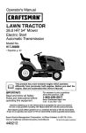
Operator's Manual
I RIIFTSHIIN°
LAwN
TRACTOR
26.0 HP,* 54" Mower
Electric Start
Automatic Transmission
Model No.
917.28863
• Espa_oi, p. 37
IMPORTANT:
For answers to your questions
Read and follow all Safety
Rules and Instructions
before
about this product, Call:
operating this equipment.
1-800-659-5917
SEARS Craftsman
5 am - 5 pm, Mort-
Help Line
Sat
Gasoline containing up to 10% ethanol (EIO) is acceptable for use in this machine.
The use of any gasoline exceeding 10% ethanol (EIO) will void the product warranty,
Esta mdquina puede utilizar gasolina con un contenido de hasta el 10% de etanol (EIO).
El uso de una gasolina que supere el 10% de etanol (EIO) anularzt la garantla del producto.
Sears Brands Management Corporation, Hoffman Estates, IL 60179 U.S.A.
Visit our Craftsman website:w_rw.sears.com/craftsman
*As rated bythe
engine
manufacturer
448214 Rev. 1
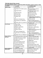
Warranty .................................................. 2
Safety Rules ............................................ 3
Product Specifications ............................. 6
AssemblyiPre-Operation ......................... 7
Operation ............................................... 13
Maintenance Schedule .......................... 21
Maintenance ..........................................
21
Sewice and Adjustments ....................... 26
Storage ..................................................
3I
Troubleshooting
.....................................
32
Sears Service .......................... Back Cover
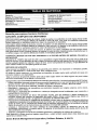
Craftsman Riding Equipment Warranty
CRAFTSMAN FULL WARRANTY
FOR TWO YEARS from the date of purchase, all non-expendable parts of this riding equipment are
warranted against any defects in material or workmanship. A defective non-expendable part will
receive free in-home repair or replacement if repair is impossible.
FOR FIVE YEARS from the date of purchase, the frame and front axis of this riding equipment are
warranted against any defects in matedal or workmanship. A defective frame or front axle will receive
free in-home repair or replacement if repair is impossible .......
FOR 90 DAYS from the date of purchase, the battery (an expendable part) of this riding equipment
is warranted against any defects in material or workmanship (our testing proves that it will not hold a
charge). A defective battery will receive free in-home replacement.
ADDITIONAL LIFETIME LIMITED WARRANTY on CAST IRON FRONT AXLE (if equipped)
FOR AS LONG AS IT IS USED bythe odginal owner after the fifth year from the date of purchase, the
cast iron front axle (if equipped) of this riding equipment is warranted against any defects in matedaI or
workmanship. With proof of purchase, a defective cast front axle will receive free in-home replacement.
WARRANTY SERVICE
For warranty coverage details to obtain free repair or replacement, call 1-800-659-5917 or visit the
web site: www.craftsman.com
In all cases above, if part repair or replacement is impossible, the riding equipment will be replaced
free of charge with the same or an equivalent model.
All of the above warranty coverage is void if this riding equipment is ever used while providing
commercial services or if rented to another person.
This warranty covers ONLY defects in matedaI and workmanship. Warranty coverage does NOT
include:
.
•
°
•
•
•
•
•
Expendable parts (except battery) that can wear out from normal use within the warranty period,
including but not limited to blades, spark plugs, air cleaners, belts, and oil filters.
Standard maintenance servicing, oil changes, or tune-ups.
Tire replacement or repair caused by punctures from outside objects, such as nails, thorns,
__stumpS,or glass.
Tire or wheel replacement or repair resulting from normal wear, accident, or improper operation or
maintenance.
Repairs necessary because of operator abuse, including but not limited to damage caused by
towing objects beyond the capability of the riding equipment, impacting objects that bend the
frame, axle assembly or crankshaft, or over-speeding the engine.
Repairs necessary because of operator negligence, including but not limited to, electrical and
mechanical damage caused by improper storage, failure to use the proper grade and amount
of engine oil, failure to keep the deck clear of flammable debris, or failure to maintain the riding
equipment according to the instructions contained in the operator's manual.
Engine (fuel system) cleaning or repairs caused by fuel determined to be contaminated or oxidized
(stale). in general, fuel should be used within 80 days of its purchase date.
Normal deterioration and wear of the exterior finishes, or product label replacement.
This warranty gives you specific legal rights, and you may also have other rights which vary f_om
state to state.
Sears Brands
Management
Corporation,
Hoffman
2
Estates,
IL 60179
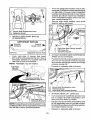
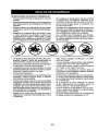
_DANGER:
This cutting machine is capable of amputating hands and feet and
throwing objects. Failure to observe the following safety instructions could result
in serious
injury or death.
_IbWARNING:
In orderto prevent accidental starting when setting up, transporting,
adjusting or making repairs, always disconnect spark plug wire and place wire where
it cannot contact spark plug.
•
_t, WARNING:
Do not coast down a hill in
neutral, you may lose control of the tractor.
_,WARNING:
Tow only the attachments
that are recommended
by and comply with
specifications
of the manufacturer
of your
tractor. (Jse common sense when towing.
Operate only at the lowest possible speed
when on a slope. Too heavy of a load, while
on a slope, is dangerous. Tires can lose
traction with the ground and cause you to
lose control of your tractor.
•
•
•
_.WARNING:
Engine exhaust, some of
its constituents, and certain vehicle components contain or emit chemicals known to
the State of California to cause cancer and
birth defects or other reproductive harm.
•
_kWARNING:
Battery posts, terminals and
related accessories contain lead and lead
compounds, chemicals known to the State of
California to cause cancer and birth defects
or other reproductive harm. Wash hands
after handling.
I. GENERAL
•
•
•
•
OPERATION
Read, understand, and follow all instructions on the machine and in the manual
before starting.
Do not put hands or feet near rotating
parts or under the machine. Keep clear
of the discharge openmg at all times.
Only allow responsible adults, who are
familiar with the instructions, to operate
the machine.
•
°
Clear the area of objects such as rocks,
toys, wire, etc., which could be picked
up and thrown by the blades.
Be sure the area is clear of bystanders
beforeoperating.
Stop machine ifanyone
enters the area.
Never carry passengers.
Do not mowin reverse unless absolutely
necessary. Always look down and behind
before and while backing.
3
Never direct discharged materialtoward
anyone.
Avoid discharging
material
agatnst a wall or obstruction.
Matenal
may ricochet back toward the operator.
Stop the blades when crossing gravel
surfaces.
Do not operate machine without the entire grass catcher, discharge chute, or
other safety devices in place and working.
Slow down before turning.
Never leave a running machine unattended.
Always turn off blades, set
parking brake, stop engine, and remove
keys before dismounting.
Disengage
blades when not mowing.
Shut off engine and walt for all parts to
co me to a complete stop before cleaning
the machine, removing the grass catcher,
or unclogging the discharge chute.
Operate machine only in dayhghtor good
artificial light.
Do not operate the machine while under
the influence of alcohol or drugs,
Watch for traffic when operating near or
crossing roadways.
Use extra carewhen loading or unloading
the machine into a trailer or truck,
Always wear eye protection when operating machine.
Data indicates that operators, age 60
years and above, are involved in a large
percentage of riding mower-related injuries. These operators should evaluate
their ability to operate the riding mower
safely enough to protect themselves and
others from serious injury.
Followthemanufacturer'srecommendation for wheel weights or counterweights.
Keep machine free of grass, leaves or
other debns build-u p which can touch hot
exhaust/engine
parts and burn. Do not
allow the mower to plow leaves or other
debris which can cause build-up to occur. Clean any oil or fuel spitfage before
operating or storing the machine. Allow
machtne to cool before storage.
II,SLOPE
OPERATION
Keep children out of the mowing area
and inthe watchful care of a responsible
adult other than the operator.
. Be alert and turn machine off if a child
enters the area.
• Before and while backing, look behind
and down for small children.
• Never carry children, even withthe blades
shut off. They mayfall offand beseriously
injured or interfere with safe machine
operation. Children who have been given
rides inthe past may suddenly appear in
the mowing area for another ride and be
run over or backed over bythe machine,
• Never allow children to operate the machine.
• Use extra care when approaching blind
corners, shrubs, trees, or other objects
that may block yourView of a child,
IV. TOWING
• Tow onlywith a machine that has a hitch
designed for towing. Donot attach towed
equipment except at the hitch point.
, Followthe manufacturer's recommendation for weight limitsfor towed equipment
and towing on slopes.
• Never allow children or others in or on
towed equipment.
• On slopes, the weightofthe towed equipment may cause loss of traction and loss
of control.
• Travel slowiy and allow extra distance to
stop.
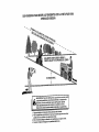
Slopes are a major factor related to loss of
control and tip-over accidents, which can
result in severe injuryor death. Operation
on all slopes requires extra caution. If you
cannot back up the slope or if you feel uneasy
on it, do not mow it,
• Mow up and down slopes, not across.
- Watch for holes, ruts, bumps, rocks, or
other hidden objects. Uneven terrain
could overturn the machine, Tall grass
can hide obstacles.
• Choose a low ground speed so that you
will not have to stop or shift while on the
stope.
• Do not mowonwetgrass.Tires maylose
traction.
....
Always keep the machine in gear when
going down slopes. Do not shift to neutral
and coast downhill.
• Avoid starting, stopping, or turning on a
slope. Ifthetireslosetraction, disengage
the blades and proceed slowly straight
down the slope.
• Keep all movement on the slopes slow
and gradual.
Do not make sudden
changes in speed or direction, which
could cause the machine to roll over.
• Use extra care while operating machine
with grass catchers or other attachments;
they can affect the stability of the machine. Do no use on steep slopes.
• Do not try to stabilize the machine by
putting your foot on the ground.
• Do not mow near drop-offs, ditches,
or embankments. The machine could
suddenly roll over if a wheel is over the
edge or if the edge caves in.
III. CHILDREN
V, SERVICE
SAFE HANDLING OF GASOLINE
To avoid personal injury or propertydamage, use extreme care in handling gasoline,
Gasoline is extremely flammable and the
vapors are explosive,
-_WARNING:
CHILDRENCAN BE INJURED.........
;--l=xtinguish aii cigarettes, cigars, pipes,
BYTHISEQUIPMENT,The American Acadeand other sources of ignition.
my of Pediatrics recommends that children
• Use only approved gasoline container,
be a minimum of 12 year of age before op• Never remove gas cap or add fuel with
erating a pedestrian controlled lawn mower
the engine running. Allow engine to cool
and a minimum of 16 years of age before
before refueling.
operating a riding lawn mower,
• Never fuel the machine indoors.
. Neverstorethemachineorfuelcontainer
Tragic accidents can occur if the operator
is not alert to the presence of children.
where there is an open flame, spark, or
Children are often attracted to the machine
pilot light such as on a water heater or
and the mowing activity. Never assume
other appliances,
. Never fill containers inside a vehicle or
that children will remain where you last
saw them.
on a truck or trailer bed with plasticliner.
Always place containers on the ground
away from your vehicle when filling.
4
*
Remove gas-powered equipment from
the truck or trailer and refuel it on the
ground. Ifthis is not possible, then refuel
such equipmentwith a portable container,
rather than from a gasoline dispenser
nozzle.
- Keep the nozzle in contact with the rim
of the fuel tank or container opening at
all times until fueling is complete. Do not
use a nozzle lock-open device.
If fuel is spilled on clothing, change clothing immediately.
e
Never overfill fuel tank. Replace gas cap
and tighten securely.
GENERAL SERVICE
.
.
•
•
°
•
•
o
•
•
•
.
•
Never operate machine in aclosed area,
Keep all nuts and bolts tightto be surethe
equipment is in safe working condition,
•
•
Nevertamperwith safetydevices, Check
their proper operation regularly.
Keep machine free of grass, leaves, or
other debris build-up. Clean oil or fuel
spillage and remove any fuel-soaked debris. Allow mashineto cool beforestoring.
If you strike a foreign object, stop and
inspectthe machine. Repair, if necessary,
before restarting,
Never make any adjustments or repairs
with the engine running.
Check grass catcher components andthe
discharge chute frequently and replace
with manufacturer's recommended parts,
when necessary.
Mowerbladesaresharp. Wraptheb]ade
or wear gloves, and use extra caution
when servicing them.
Checkbrakeoperationfrequentty. Adjust
and service as required.
Be alert and turn machine off if a child
enters the area,
• Before and while backing, look behind
and down for small children.
• Mow up and down slopes (15° Max), not
across.
• Choose a low ground speed so that you
wilt not have to stop or shift while on the
slope.
• Avoid starting, stopping, or turning on a
.blades shu_.o%__They.may.fa!.!_offa[ld
slope. ]fthetireslosetraction, disengage
be seriously injured or interfere with safe .................
the bla,€lesand proceed s!ov¢ly-straight
machine operation, Children who have
down the slope.
been given ridesinthe pastmay suddenly
• If machine stops while going uphill,
appear in the mowing area for another
disengage blades, shift into reverse and
ride and be run over or backed over by
back down slowly.
the machine.
• Do not turn on slopes unless necessary,
Keep children out of the mowing area
and then, turn slowly and gradually
and in the watchful care of a responsible
downhill, if possible.
adult other than the operator.
• Whenloading or unloadingthis machine,
do not exceed the maximum recommended operation angle of t5 °.
Maintain or replace safety and instruction
labels, as necessary.
Be sure the area is clear of bystanders
before operating, Stop machine if anyone
enters the area.
Never carry passengers.
Do not mowin reverse unless absolutely
necessary. Always look down and behind
before and while backing,
Never carry children,
even with the
5
PRODUCT
SPECIFICATIONS
iGasoline Capacity
and type:
3.0 Ga[lons/11,35 L
Regular Unleaded
OilType:
(APh SG-SL)
SAE30
(above 32°F/0°C
SAE 5W30 (below 32°F/0°C
Oil Capacity:
Wi Filter;
W/out Filter:
Spark Plug:
Champion QC12YC
(Gap: .040"/1.02 mm)
Charging
System:
16 Amps @3600 RPM
Battery:
Amp/Hr;
Min, CCA:
Case size:
Blade Bolt Torque:
45-55 Ft. Lbs,/62-75
64 Oz./1.96 L
60 Oz./1.77 L
28
230
U1R
Nm
CONGRATULATIONS on your purchase of
a new tractor. It has been designed, engineered and manufactured togiveyouthe best
possible dependability and performance.
....................
Should you experience any problem you cannot easily remedy, please contact a Sears or
other qualified service center, We have competent, well4rained representatives and the
proper tools to service or repair this tractor.
Please read and retain this manual. The
instructions will enable you to assemble
and maintain your tractor properly. Always
observe the "SAFE-rY RULES",
CUSTOMER
Inthe stateof Califomiathe above is required
by law (Section 4442 of the California Public
Resources Code). Other states may have
similar laws, Federal laws apply on federal
lands. A spark arrester for the muffler is
available through your nearest Sears service
center (See REPAIR PARTS manual),
REPAIR PROTECTION AGREEMENTS
Congratulations on making a smart purchase, Your new Craftsman® product is
designed and manufactured for years of
dependable operation. But like all products,
itmay require repairfrom time to time. That's
when having aRepair ProtectionAgreement
can save you money and aggravation,
Purchase a Repair Protection Agreement
now and protect yourself from unexpected
hassle and expense.
Here's what's included in the Agreement:
;
Expertservice byour I2,000 professional
repair specialists.
•
Unlimitedserviceand
no chargefor
and labor on all covered repairs.
•
Product replacement
product can't be fixed.
•
Discount of 10% from regular price of
service and service-related
parts not
covered bythe agreement; also, 10% off
regular price of preventive maintenance
check.
.
Fast help by phone - phone support
from a Sears representative on products
requiring in-homerepair, plus convenient
repair scheduling.
RESPONSIBILITIES
- Read and observe the safety rules.
• Followa regular schedule in maintaining,
caring for and usingyour tractor.
• Follow instructionsunder "Maintenance"
and "Storage" sections of this manual.
• Wear proper Personal Protective Equipment (PPE) while operating this machine,
including (at a minimum) sturdy footwear,
eye protection, and hearing protection.
Do not mow in shorts and/or open toed
footwear.
if your
parts
covered
Onceyou purchase the Agreement, a simple
phone call is all that it takes for you to scheduleservice. Youcan call anytime day or night,
or schedule a service appointment online.
Sears has over 12,000 professional repair
•--Always letsomeone knowyou are outside ......specialists,, who have access to over.4,5mowing,
million quality parts and accessories. That's
the kind of professionalism you can count on
_WARNING:
This tractor is equipped with
to help prolong the life of your new purchase
an internal combustion engine and should
for years to come. Purchase your Repair
not be used on or near any unimproved
Protection Agreement today!
forest-covered, brush-covered or grassSome limitations and exclusions apply.
covered land unless the engine's exhaust
For prices and additional information call
system is equipped with a spark arrester
1-800-827-6655.
meeting appficable local or state laws (if
SEARS INSTALLATION SERVICE
any). If a spark arrester is used, it should
be maintained in effective working order by
For Sears professional installation of home
the operator.
appliances, garage door openers, water
heaters, and other major home items,in the
U.S.A. call 1-800-4-MY-HOME®
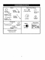
Mower
(2) Rear _
Lift Link
j_
Assemblies
(5)
O,D.1-3/16
Washers
(1) Shoulder Bolt
(1) 1-1/40.D,
Washer
(1) Small
Retainer Springs
(1) Front _
Lift Link
_,'_\
Assembly
(1) Wheel
(1) 3/8-16
Locknut
Retainer Springs
.................................................................
....
if Equipped
....
(_
(1) Anti-Sway Bar
Keys
(1) 3/40.D.
Washers
(1) Small Retainer
Springs
i i i,,,,,,,
(2) Keys
i H,,
*Installed by Dealer
*BrushGuard Kit
7
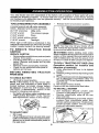
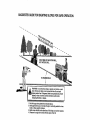
i'.....................
Slope Sheet
Your new tractor has been assembled at the factory with exception of those parts left unassembled for shipping purposes. To ensure safe and proper operation of your tractor all parts
and hardware you assemble must be tightened securely. Use the correct tools as necessary
to ensure proper tightness.
TOOLS
REQUIRED
FOR ASSEMBLY
•
Release lever to lock seat in position.
A socket wrench set will make assembly
easier. Standard wrench sizes are listed.
(2) 7/16" wrenches
Utility knife
(1) 1/2" wrench
Tire pressure gauge
(I) 3/4" wrench
Pliers
(1) 3/4" socket w/drive ratchet
(1) 9/16" wrench
Flashlight
When right or left hand is mentioned in this
manual, it means when you are in the operating
position (seated behind the steering wheel).
.....................TO
REMOVE
TRACTOR
FROM
CARTON
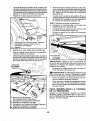
UNPACK CARTON
• Removeallaccessibleloosepartsandparts
cartons from carton.
• Cutalongdotted lineson all four panels of
carton.Remove end panels and lay side
panelsflat.
• Remove mower and packingmaterials.
• Check for any additional loose partsor
cartonsand remove.
BEFORE REMOVING
FROM SKID
TO CHECK
TRACTOR
BATTERY
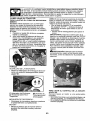
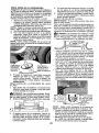
1. Lift hood to raised position.
NOTE: If this battery is put into service after
month and year indicated on label (label is
located between terminals) charge battery
for minimum of one hour at 6-10 amps. (See
"BATTERY" in Maintenance
section of this
manual for charging instructions),
, -Forbattery& batterycable installationsee
"REPLACING BATTERY" in the "Service
and Adjustments" section in this manual.
NOTE: You may now roll your tracter off the
skid. Follow the appropriate instruction below
to remove thetractor from the skid.
_ll WARNING; Before starting, read, understand and followall instructions inthe Operation
section of this manual. Be sure tractor is in a
well-ventilated area. Be sure the area in front
of tractor is clear of other people and objects.
TO ROLL
Operation
TRACTOR
section
(See
and
function
of controls)
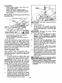
1. Raise attachment lift lever to its highest
position.
2. Release parking brake bydepressing brake
pedal.
3. Placefreewheel controlin disengaged position to disengage transmission (See "TO
TRANSPORT" in the Operation section of
this manual).
4. Roll tractor forward off skid.
Continue with the instructions that follow.
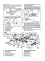
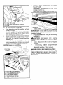
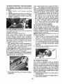
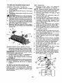
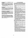
TO INSTALL
MOWER
1.
SET PARKING BRAKE LEVER AND
.....
LOWER ATTACHMENT LIE-I-LEVER
•
Depress clutch/brake pedal all the way
down and hold.
•
Pull parking brake lever up and hold, release
pressure from clutch/brake pedal, then
release parking brake lever. Pedal should
remain in brake position. Ensure parking
brake will hold tractor secure.
Label
TO ADJUST SEAT
• Sitin seat.
• Lift upadjustmentlever (A) andslide seat
untilacomfortablepositionisreachedwhich
allows youto pressclutch/brakepedalall
the way down.
OFF SKID
for location
Brake Lever
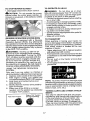
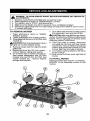
3. TURN STEERING WHEEL LEFT AND
POSITION MOWER
• Turn steering wheel to the left as far as it
will go and position moweron rightside of
tractor with deflector shield (Q)tothe right.
_CAUTION:
Lift lever is spring loaded.
Have a tight grip on lift lever, lower it slowly
and engage in lowest position. Lift lever is
located on left side of fender.
Li_
Lever
Front
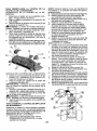
2. ASSEMBLE FRONT GAUGE WHEEL
(W) TO FRONT OF MOWER
Transaxle
Q. DeflectorShield
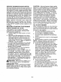
4. SLIDE MOWER UNDER TRACTOR
•
H.
W.
X.
Y.
Z.
Front Mower Bracket
Front Gauge Wheel
Shoulder Bolt
1-I/40.D. Washer
3/8-16 Locknut
Bring beltforwardand check beltfor proper routing in all mower pulley grooves.
NOTE: Be sure mower side suspension
arms (A) are pointing forward before sliding
mower under tractor.
• Slide mower under tractor until it is
centered under tractor.
A.
B.
C.
D.
E.
E
H,
Mower Side Suspension Arms
Retainer Spring
Rear Uft Link(S)
Right Side Rear Mower Bracket
Front Lift Link Assembly
Front Suspension Bracket
Front Mower Bracket
I.
K.
L.
M.
Q.
S.
W.
9
Left Side Rear Mower Bracket
Belt Tension Rod
Locking Bracket
Engine Clutch Pulley
De,rector Shield
Anti-Sway Bar
Front Gauge Wheel
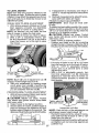
•
•
Pivot the integrated washer end of antisway bar (S)towards mower deck bracket
on right side of mower, Insert integrated
washer end of bar into hole in rear mower
bracket (D). Move mower as needed to
insert integrated washer end of bar into
rear mower bracket (D),
Secure with small washer and small
retainer spring as shown.
A, MowerSide Sus _ensionArms
Q. DeflectorShield
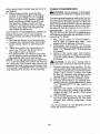
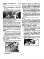
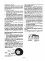
5. INSTALL ANTI-SWAY BAR (S)
(IF EQUIPPED)
'
ANTI-SWAY
Ldi" Towards
I ""_ Transaxle
90° End
BAll
(S)
Towards"_
MowerDeck
D,
S.
T.
IntegratedWasherEnd
6,
•
From right side of mower, first insert
90_ end of anti-sway bar (S) into hole in
transaxle bracket (T), located near left
rear tire in front of transaxle,
NOTE: Flashlight may be helpful.
"t
t3
Anti-Sway
!_
!.,'-__...............
_,_
Bar(S)
_,._.::
:_:.>
._
Location...,
] ;
\
°
Right Side Rear Mower
Anti-Sway
Bar
Transaxle Bracket
Bracket
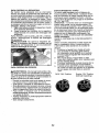
ATTACH MOWER SIDE SUSPENSION
ARMS (A) TO CHASSIS
Position front hole inside suspension arm
(A) over pin on outside of tractor chassis
and secure with large washer and large
retainer spring (B),
Repeat on opposite side of tractor.
Transaxle Bracket (T)
Located Between Rear Tires
A, Mower Side Suspension Arms
B. Retainer Spring
D. Right Side Rear Mower Bracket
7. ATTACH REAR LIFT LINKS (C)
• Insert rod end of rear lift link (C) into hole
(U) in tractor lift shaft suspension arm
and pivot link down to mower,
• Lift rear corner of mower and position slot
in link assembly over pin on rear mower
bracket (D) and secure with largewasher
and large retainer spring.
• Repeat on opposite side of tractor.
T. Transaxle Bracket
NOTE: Depending onmodel, bracket (_ may
be differentthan shown but hole for anti-sway
bar wilt be in same position!location,
10
9
•
•
INSTALL BELT ON ENG1NE CLUTCH
PULLEY (M)
Disengage belt tension rod (K) from
locking bracket (L).
Install belt onto engine clutch pulley (M),
C. Rear Lift Link(s)
D, Right Side Rear Mower Bracket
U. Hole
8 ATTACH FRONT LINK (E)
M.Engine
Clutch Pulley
• Turn steering wheel to position wheels
straight forward.
IMPORTANT: Check belt for proper routing
• From front of tractor, insert rod end of in all mower pulley grooves and under
front link (E) through front hole intractor
mandrel covers.
front suspension bracket (F),
• Engage belt tension rod (14)on locking
• Moveto left side of mower and and insert
bracket (L),
large retainer spring (G) through hole in
_OAUTION:
Belt tension rod is spring
front link (E) behind front suspension
loaded. Have atight grip on rod and engage
bracket (F).
slowly,
° Insert other end of link (E) into hole in
• Raise attachment rift lever to highest
front mower bracket (H) and secure with
position.
washer and small retainer spring (J).
• If necessary, adjust gauge wheels
NOTE: Requires deck lifting,
before operating mower as shown in the
Operation section of this manual.
Front Unk
/
MOWER DRIVE BELT INSTALLATION
l
f ,,_
_ .....
/.........
",
Follow procedure described in "TO
REPLACE MOWER BLADE DRIVE BELT"
in the "Service and Adjustments" section of
this manual.
J. Small Retainer Spring
M. Engine Clutch Pulley
11
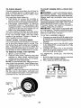
CHECK TIRE PRESSURE
The tires on your tractor were overinflated
at the factory for shipping purposes. Correct tire pressure is important for best
cutting performance.
* Reduce tire pressureto PSI shown on
tires.
CHECK DECK LEVELNESS
For best cutting results, mower housing
should be properly leveled. See "TO
LEVEL MOWER" in the Service and Adjustments section of this manual
CHECK FOR PROPER POSITION
OF ALL BELTS
See the figures that are shown for replacing motion and mower blade drive belts
in the Service and Adjustments section
of this manual. Verify that the belts are
routed correctly.
CHECK BRAKE SYSTEM .........
After you learnhow to operateyour trac-
t_CHECKLIST
Before you operate your new tractor, we
wish to assure that you receive the best
performance and satisfaction from this
Quality Product.
Please review the following checklist:
J All assembly instructions have been
completed.
J No remaining loose parts in carton.
t/' Battery is properly prepared and
charged.
t/' Seat is adjusted comfortably and tightened securely.
t/' All tires are properly inflated, (For shipping purposes, the tires were overinfiated
at the factory).
Vr Be sure mower deck is property leveled
side-to-side/front-to-rear for best cutting
results. Fires must be properlyinflated
for leveling).
J Check mower and drive belts. Be sure
tor, check to see that the brake is operating properly. See "TO CHECK BRAKE"
in the Service and Adjustments section of
this manual.
they are routed properly around pulleys
and inside all belt keepers.
v( Check wiring. See that all connections
are still secure and wires are properly
clamped.
J Before driving tractor, be sure freewheel
control is in"transmission engaged" position (see "To Transport" in the Operation
section of this manual),
While learning how to use your tractor, pay
extra attention to the following important
items:
V" Engine oil is at proper level.
J' Fueltank isfilled withfresh, ctean, regular
unleaded gasoline,
J Become familiar with all controls, their
location and function. Operate them
before you start the engine.
_f_ Be s ure brake system is insafe operating
condition.
i,/Be sure Operator Presence System and
Reverse Operation System (ROS) are
working properly (See the Operation and
Maintenance sections in this manual).
J It is important to purge the transmission
before operating your tractor for the first
time. Follow proper starting and transmission purging instructions (See "TO
START ENGINE" and "PURGE TRANSMISSION" inthe Operation section ofthis
manual).
12
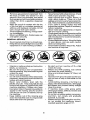
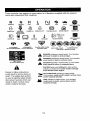
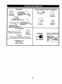
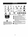
These symbols may appear on your tractor or in literature supplied with the product.
Learn and understand their meaning.
R
ENGINE
LIGHTS
H
N
REVERSE
OFF
ON
REVERSE
OPERATION
SYSTEM
(ROS)
FUEL
ATTACHMENT
CLUTCH
DISENGAGED
I',,!
L
HIGH
NEUTRAL
LOW
CHOKE
FAST
SLOW
IGNITION
ENG|NE
BATTERY
ON
ENGINE
REVERSE
ATTACHMENT
CLUTCH
ENGAGED
START
PARKING
FORWARD
DANGER,
KEEP HANDS
AND FEETAWAY
BRAKe
CRUISE
KEEP
MOWI_R
CONTROL
AREA CLEAR
(SEE SAFETY
HEIGHT
SWITCH
MOWER
LIFT
CLUTCH/BRAKE
PEDAL
SLOPE HAZARDS
RULES SECTION)
DANGER
if not avoided,
will
result indicates
in death aorhazard
seriouswhich,
injury,
WARNING
hazard
which,
if not avoided,
could resultindicates
in deatha or
serious
injury.
FREEWHEEL
{Automatic Models only)
CAUTION
indicates
a hazard
which, injury.
if not avoided,
m_ght result
in minor
or moderate
&
CAUTION when used without the alert symbol,
indicates a situation that could result in damage
to the tractor and/or engine,
Failure to follow instructions
could result in serious injury or
death. The safety alert symbol
is used to identify safety information about hazards which can
result in death, serious injury
and!or property damage.
HOT SURFACES indicates a hazard which,
if not avoided, could result in death, serious injury
damage,
.,,,_,_,._.and!or property
/_,
FIRE indicates a hazard which, if not avoided,
could result in death, serious injury and/or
property damage.
13
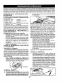
KNOW YOUR TRACTOR
READ THIS MANUAL AND SAFETY RULES BEFORE OPERATING YOUR TRACTOR
Compare the illustrations with your tractor to familiarize yourself with the locations of
various controls and adjustments. Save this manual for future reference.
Our tractors conform to the applicable safety standards of the
American National Standards Institute.
(A) ATTACHMENT LIFT LEVER - Used to
raise and lower the mower or other attach-
(H) LIGHT SWITCH - Turnsthe headlights
on and off.
ments mounted to your tractor.
(B) BRAKE PEDAL - Used for braking the
tractor and starting the engine,
(C)-PARKING BRAKE_-E(_ks_lutcS/SraKe
pedal into the brake position.
(D) THROTTLE/CHOKE CONTROL- Used
for starting and controllingengine speed.
(E) ATTACHMENT CLUTCH SWITCH
- Usedtoengagethemowerblades, orother
attachments mounted to your tractor,
(F) IGNITION SWITCH - Used for starting
and stopping the engine,
(G) REVERSE OPERATION SYSTEM
(ROS) "ON" POSITION - Allows operation
of mower or other poweredattachment while
in reverse,
14
(J) CRUISE CONTROL LEVER - Used to
set forward movement of tractor at desired
speed without holding the forward drive
pedal
(K) FORWARD DRIVE PEDAL - Used for
forward movement of tractor.
(L) REVERSE DRIVE PEDAL- Used for
reverse movement of tractor.
(M) FREEWHEELCONTROL-Disengages
transmission for pushing or slowly towing
the tractor with the engine off.
(P) SERViCEREMINDER/HOURMETER
- Indicates when service is required for the
engine and mower.
The operation of any tractor can result in foreign objects thrown into
the eyes, which can result in severe eye damage. Always wear safety
glasses or eye shields while operating your tractor or performing any
adjustments or repairs. We recommend standard safety glasses or a
wide vision safety mask worn over spectacles.
HOW TO USE YOUR TRACTOR
TO SET PARKING BRAKE
'(our tractor is equippedwith an operator
presence sensing switch. When engine is
running, any attempt bythe operatorto leave
the seat withoutfirst setting the parking brake
will shut off the engine.
1. Depress brake pedal (B) allthe way down
and hold.
2. Pull parking brake lever (C) up and hold,
release pressure from brake pedal (B),
then release parking brake lever. Pedal
should remain in brake position. Make
sure parkingbrakewi]l holdtractorsecure.
.....
NOTE: Failure to move throttle control
between half and full speed (fast) position, before stopping, may cause engine
to "backfire".
• Turn ignition key (F) to "STOP" position
and remove key. Always remove keywhen
leaving tractor to prevent unauthorized
use.
• Never use choke to stop engine.
IMPORTANT: Leaving the ignition switch in
any position other than "STOP" will cause
the battery to discharge and go dead,
NOTE: U0dercertain conditions whentractor
isstanding idlewith the engine running, hot
engine exhaust gases may cause "browning" of grass. To eliminate this possibility,
always stop engine when stopping tractor
on grass areas.
_J_GAUTION: Always stop tractor completely, as described above, before leaving
the operator's position.
STOPPING
MOWER BLADES - To stop mower blades, push attachment
clutch switch into disengaged position (O).
(1)Attachment
ClutchSwitch
PullOut To"Engage"
STOPPING
TO USE THROTTLE CONTROL (D)
Always operate engine at full speed (fast),
• Operating engine at less than full speed
(fast) reduces engine's operating efficiency.
• Full speed (fast) offers the best mower
performance.
(O) Push-Into
"Disengaged"
GROUND DRIVE • Tostop ground drive, depress brake pedal
all the way down.
ENGINE • Move throttle control (D) between half and
full speed (fast) position.
15
TO MOVE FORWARD AND BACKWARD
The direction and speed of movement is
controlled by the forward and reverse drive
pedals.
1. Start tractor and release parking
brake.
2. Slowly depress forward (K) or reverse(L)
drive pedal to begin movement. Ground
speed increases the further down the
pedal is depressed.
The cutting height range is approximately 1"
to 4". The heights are measured from the
groundtothe bladetip with the engine not running. These heights are approximate and may
vary depending upon soil conditions, height
of grass and types of grass being mowed.
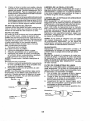
• The average lawn should be cut to approximately 2-1/2" during the cool season and to over 3" during hot months.
For healthier and better looking lawns,
mow often and after moderate growth.
- For best cutting performance, grass over
6 inches in height should be mowed
twice. Make the first cut relatively high;
the second to desired height,
TO ADJUST
TO USE CRUISE CONTROL
The cruise control feature can be used for
forward travel only.
SYSTEM CHARACTERISTICS
The cruise control should only be used
while mowing or transporting on relatively
smooth, straight surfaces. Other conditions
such as trimming at slow speeds may cause
the cruise control to disengage. Do not use
the cruise control on slopes, rough terrian
or while trimmimg or turning.
• With forward drive pedal depressed to
desired speed, pull cruise control lever
(J) up and hold while lifting your foot off
the pedal, then release the lever.
To disengage the cruise control, depress the
brake pedal, tap on forward drive pedal or
push the cruise control lever down,
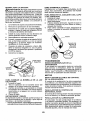
TO ADJUST MOWER CUTTING HEIGHT
The position of the attachment lift lever (A)
determines the cutting height.
- Put attachment lift lever indesired cutting
height slot.
GAUGE
WHEELS
Gauge wheels are properly adjusted when
they are slightly offthe ground when mower
is at the desired cutting height in operating
position. Gauge wheels then keep the deck
in proper position to help prevent scalping
in most terrain conditions,
NOTE: Adjust gauge wheels with tractor on
a flat tevel surface.
1. Adjust mower to desired cutting height
(See "TO ADJUST MOWER CUTTING
HEIGHT" in this section of manual).
2. With mower in desired height of cut position, gaugewheels
should be assembled
so they are slightly off the ground, tnstall
gauge wheel in appropriate hole. Tighten
securely.
3, Repeat for all, installing gauge wheel in
same adjustment hole.
TO OPERATE MOWER
"four tractor is equipped with an operator
presence sensing switch. Any attempt bythe
operator to leave the seat with the engine
running and the attachment clutch engaged
will shut off the engine. You must remain
fully and centrally positioned in the seat to
prevent the engine from hesitating or cutting
offwhen operating your equipmenton rough,
rolling terrain or hills,
t. Select desired height of cut with attachment lift lever.
2, Start mower blades by engaging attachment clutch control.
16
TO OPERATE ON HILLS
TO STOP MOWER BLADES _.,Disengage attachment clutch control.
_WARNING:
Do not drive up or down
hills with slopes greater than 15° and do not
drive across any slope. Use the slope guide
provided at the back of this manual.
• Choose the slowest speed before starting
up or down hills.
• Avoid stopping or changing speed on hilts.
• If stopping is absolutely necessary, push
brake pedal quickly to brake position and
engage parking brake,
• Torestart movement, slowly release parking brake and brake pedal.
• Slowly depress appropriate drive pedal to
slowest setting.
• Make all turns slowly.
_HILGAUTION. Do not operate the mower
without either the entire grass catcher, on
mowers so equipped, orthe deflector shield
(S) in place.
REVERSE OPERATION SYSTEM (ROS)
Your tractor is equipped with a Reverse
Operation System (ROS). Any attempt by
the operator to travel inthe reverse direction
:...........
_With the attachment clutch engaged wit l shut
off the engine unless ignition key is placed
in the ROS "ON" position.
_kWARNING: Backing up with the attachment clutch engaged while mowing
is strongly discouraged. Turning the ROS
"ON", to allow reverse operation with the
attachment clutch engaged, should only
be done when the operator decides it is
necessary to reposition the machine with
the attachment engaged. Do not mow in
reverse unless absolutely necessary.
USING THE REVERSE OPERATION
SYSTEM Only use if you are certain no children or
other bystanders will enterthe mowing area,
1. Depress brake pedal all the way down.
2, With engine running, turn ignition key
counterclockwiseto ROS "ON" position.
3. Look down and behind before and
while backing,
4.-,-Slowly depress reverse drive pedaLto_
start movement.
5. When use of the ROS is no longer
needed, turn the ignition key clockwise
to engine "ON" position.
ROS
"ON" Position
TO TRANSPORT
When pushing or towing your tractor, be
sure to disengage transmission by placing
freewheel control in freewheeling position.....
Free wheel control is located at the rear
drawbar of tractor,
- Raise attachment lift to highest position
with attachment lift control,
• Pull freewheel control out and into the slot
and release so it is held in the disengaged
position.
• Do not push or tow tractor at more than
two (2) MPH.
• To reengage transmission, reverse above
procedure.
NOTE: To protect hood from damage when
transporting yourtractor on a tr_jckoratrailer,
Use an appropriate means of tying hood to
tractor (rope, cord, etc.),
TOWING CARTS AND OTHER ATTACHMENTS
Tow only the attachments that are recommended by and comply with specifications
of the manufacturer of your tractor. Use
common sense when towing. Too heavy
of a load, while on a slope, is dangerous.
Tires can lose traction with the ground and
cause you to lose control of your tractor.
Engine "ON" Position
(Normal Operating)
17
CAUTION: Alcohol blended fuels (called
SERVICE REMINDER/HOUR METER
gasohol or using ethanol or methanol) can
Service reminder shows the total number of
hoursthe enginehas run and indicates when attract moisture which leads to separation
and formation of acids during storage.
the engine or mower needs servicing. After
every 50 hoursof operation the oilcan icon Acidic gas can damage the fue! system
of an engine while in storage. To avoid
willstay onfor 2 hoursor untila manual reset
occurs. To reset the display manually turn engine problems, the fuel system should
be emptied before storage of 30 days
the ignition switch to the on position,then
the off positionfive times (1 second on, 1 or longer. Drain the gas tank, start the
engine and let it run until the fuel lines
second oft). To service engine and mower,
and carburetor are empty. Use fresh fuel
see the Maintenance section ofthismanual.
next season, See Storage Instructions for
Note: Service reminder runs when the
additional information. Never use engine
ignition key is in any position but "STOP",
or carburetor cleaner products in the fuel
For accurate reading, be sure key remains
tank or permanent damage may occur.
in the "STOP" position when engine is not
TO START ENGINE
running.
When starting the engine for the first time
BEFORE STARTING THE ENGINE
or if the engine has run out of fuel, it will
CHECK ENGINE OIL LEVEL
take extra cranking time to move fuel from
The engine in your tractor has been
the tank to the engine.
........................
shipped, from the factory, already filled
1, Be sure freewheel control is in the
with summer weight oil.
transmission engaged position.
1. Check engine oil with tractor on level
2. Sit on seat in operating position,
ground.
depress brake pedal and set parking
2. Remove oil fill cap/dipstick and wipe
brake.
clean, reinsert the dipstick and screw
3. Move attachment clutch to disengaged
cap tight, wait for a few seconds, reposition,
move and read oil level. If necessary,
4. Move throttle control to choke position,
add oil until "FULl" mark on dipstick is
NOTE: Before starting, read the warm
reached. Do not overfill.
and cold starting procedures below.
• For cold weather operation you should
5. Insert key into ignition and turn key
change oil for easier starting (See the
clockwise to start position and release
oil viscosity chart in the Maintenance
key as soon as engine starts. Do not
section of this manual).
run starter continuously for more than
• To change engine oil, see the Maintefifteen seconds per minute. If the
nance section in this manual,
engine does not start after several
• Fill fuel tank to bottom of filler neck. Do
attempts, move throttle control to fast
not overfill. Use fresh, clean, regular
position, wait a few minutes and try
unleaded gasoline with a minimum of
again, If engine still does not start,
87 octane. (Use of leaded gasoline will
move the throttle control back to the
increase carbon and lead oxide deposits
choke position and retry.
and reduce valve life). Do not mix oil
_WA._RM
WEATHE R STARTING
_with gasoline. Purchase.)'uel.inquanti.-.
(50°F(10°C) and above)
ties that can be used within 30 days to
assure fuel freshness.
6. When engine starts, move the throttle
CAUTION: Wipe off any spilled oil or
control to the fast position,
, Do not store, spill or use gasoline
• The attachments and ground drive can
now be used, tf the engine does not
near an open flame.
accept the load, restart the engine and
IMPORTANT: When operating in temperallow it to warm up for one minute using
atures below 32°F(0°C), use fresh, clean
the choke as described above.
winter grade gasoline to help insure good
cold weather starting.
18
COLD WEATHER STARTING (50°F(10°C)
and below)
6. When engine starts, leave throttle
control in choke position until engine
warms up and begins to run roughly.
Once rough running begins, immediately move the throttle control to the
fast position. Engine warm-up may
take from several seconds to several
minutes (the colder the temperature,
the longer the warm-up).
AUTOMATIC TRANSMISSION WARM UP
Before driving the unit in cold weather,
the transmission should be warmed up as
follows:
1, Be sure the tractor is on level ground.
2. Release the parking brake and let the
brake slowly return to operating position.
3. Allow one minute for transmission to
warm up. This can be done during
the engine warm up period.
• The attachments can also be used during the engine warm-up period after the
transmission has been warmed up.
NOTE: Ifata highaltitude (above 3000feet)
or in cold temperatures (below 32°F(0°C))
the carburetor fuel mixture may need to be
adjusted for best engine performance (see
"TO ADJUST CARBURETOR" inthe Service
and Adjustments section of this manual).
PURGE TRANSMISSION
_i_,CAUTION: Never engage or disengage
freewheel lever while the engine is running.
Toensure proper operationand performance,
it is recommended that the transmission be
purged before operating tractor for the first
time. This procedure will remove anytrapped
air inside the transmission which may have
developed during shipping of your tractor,
IMPORTANT: Should your transmission
require removal for service or replacement,
itshould be purged after reinstallation before
operating the tractor.
1. Place tractor safely on a level surface that is clear of objects and open - with
engine off and parking brake set.
2. Disengage transmission
by placing
freewheel control indisengaged position
(See "TO TRANSPORT" in this section
of manual),
3. Sitting in the tractor seat, start engine,
After the engine is running, move throttle
control to slow position. Disengage parking brake,
_CAUTION:
At any time, during step 4,
there may be movement of the drive wheels,
4, Depress forward drive pedal to full forward position and hold for five (5)seconds
and release pedal. Depress reverse drive
pedal to full reverse position and hold
for five (5) seconds and release pedal.
Repeat this procedure three (3) times.
5, Shutoff engine and set parking brake.
6. Engage transmission by placing freewheel control in engaged position (See
"TO TRANSPORT" in this section of
manual).
7. Sitting in the tractor seat, start engine.
After the engine is running, move throttle
control to half (t/2) speed. Disengage
parking brake;
8. Drive tractor forward for approximately
five feet then backwards for five feet.
Repeat this driving procedure three
times.
Your transmission is now purged and now
ready for normal operation.
19
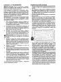
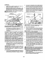
MOWING TIPS
• Tire chains cannot be used when the
mower housing is attached to tractor.
• Mower should be properly leveled for best
mowing performance. See "TO LEVEL
MOWER HOUSING" in the Service and
Adjustments section of this manual.
• The left hand side of mower should be
used for trimming.
• Drive sothat clippings are discharged onto
the area that has already been cut. Have
the cut area to the right ofthe tractor. This
will result in a more even distribution of
clippings and more uniform cutting.
• When mowing large areas, start byturning
to the right so that clippings will discharge
away from shrubs, fences, driveways,
etc. After one or two rounds, mow in the
opposite direction making left hand turns
until finished.
_f
• If grass is extremely tail, it should be
mowed twice to reduce load and possible
fire hazard from dried clippings. Make
first cut relatively high; the second to the
desired height.
° Do not mow grass when it is wet. Wet
grass will plug mower and leave undesirable clumps. Allow grass to dry before
mowing.
• Always operate engine at full throttle
when mowing to assure better mowing performance and proper discharge
_of _mate..r_ia!..
_Regulate_gr_Qu_.d_s
pe_ed__
by__
selecting a low enough speed to give the
mower cutting performance as well as the
qualm:/of cut desired.
• When operating attachments, select a
ground speed that will suit the terrain and
give best performance of the attachment
being used.
2O
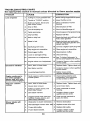
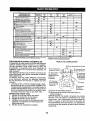
MAINTENANCE
a_o_=
SCHEDULE
Cheek
Brake
Check
Tire
Cheek
Operator
................
Presence
& ROS
A Check
_orLoose
Fasteners
C
Ghost/Replace
T
_brieation
0
Check Batte_
R
B
USE
Ope_tion
Pressure
Ev¢_
_c.
Systems
tf
"@
V'
V'
Debris
Check
Trar_saxle
Cheo_{
Mower
C_nclP.
Change
I
V'
RE Clear
inspect
_
............
,,::,,,,,
I_s
Cooling
_
,v'
,
Levelr_es8
...........
............
I
Lev_,! ...............
If
V
_
I.
_
OIl (with oil fiItet)
Er_gine, Oil lwilheut
eiE filter)
V',=
..........
Air Rlter
V_
MuffledSp=rk
i
V_=
Arrestor
.................
N: Reptace OII Fi!t,e,r,,,,!!f
eqLtipped)
E
v"
,............
G Clea_Air Screen
I
SEPOnE
S_EO. STO_AO_
Vr_
Steerlng Plate
En,g_ne Oil
Engine
_VERY
_eo
If
CheekY-So=re
Check
_F.nY
HOURS
,............
V
Off
so
HOURS
" .....
Chart
Le,_el
EVSn¥
2s
HOURS
'
Mower Blades
Ctean
f GV_RV
I
HOURS
_,_
Clean Engine Cog!ingFins
................
t4#'=
Replace Spexk P1£,£1
Rap[see
Rap!ace
Air Fqlter Paper
Carlridge
Fuel,Filter
V_
.................
I_
t
i
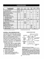
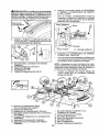
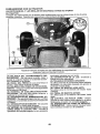
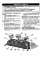
LUBRICATION CHART
GENERAL RECOMMENDATIONS
The warrantyon thistractordoes not cover
items that have been subjected to operator
abuse or negligence, To receive full value
from the warranty, operator must maintain
tractor as instructed in this manual.
Some adjustments will need to be made periodically to properly maintain your tractor.
At least once a season, check to see if
you should make any of the adjustments
.described.in the Service arid Adjustments
section of this manual,
. At least once a year you should replace
the spark plug, clean or replace air filter,
and check blades and belts for wear. A
new spark plug and clean air filter assure
proper air-fuel mixture and help your engine run better and last longer.
_Steering
Zerk
Wheel
Bearing
Zerk
Pivot Bolts
Spindle
Zerk
Front Wheel
Bearing Zerk
Engine
Gear
Teeth
Mandrel
Zerks
OGeneral Purpose Grease
(_Refer to Maintenance"ENGfNE" Section,
BEFORE EACH USE
1. Check engine oil level.
2. Check brake operation,
3, Checktire pressure,
4. Check operator presence and
ROS systems for proper operation.
5. Check for loose fasteners.
IMPORTANT: Do not oil or grease the pivot
points which have special nylon bearings..
Viscous lubricants will attract dust and dirt
thatwitl shorten the life of the self-lubricating
bearings, lfyoufeetthey must be lubricated,
use only a dry, powdered graphite type
lubricant sparingly.
21
TRACTOR
Always observe safety rules when performing any maintenance.
BRAKE OPERATION
if tractor requires more than five (5) feet to
stop at highest speed in highest gear on a
level, dry concrete or paved surface, then
brake must be serviced. (See "TO CHECK
BRAKE" in the Service and Adjustments
section of this manual).
TIRES
• Maintain proper air pressure in all tires
(See PSi on tires),
• Keep tires free of gasoline, oil, or insect
control chemicals which can harm rubber,
• Avoid stumps, stones, deep ruts, sharp
objects and other hazards that may
cause tire damage.
NOTE: To seal tire punctures and prevent
flat tires due to slow leaks, tire sealant
.......................
may be purchased from your local parts
dealer, Tire sealant also prevents tire dry
rot and corrosion.
OPERATOR PRESENCE SYSTEM AND
REVERSE OPERATION SYSTEM (ROS)
Be sure operator presence and reverse
operation systems are working properly. If
your tractor does not function as described, repair the problem immediately.
• The engine should not start unless the
brake pedal is fully depressed, and
the attachment clutch control is in the
disengaged position.
CHECK OPERATOR PRESENCE
SYSTEM
o When the engine is running, any attempt by the operator to leave the seat
without first setting the parking brake
should shut off the engine,
• When the engine is running and the
attachment clutch is engaged, any at.-temptby the operatorto leavethe seat
should shut off the engine.
• The attachment clutch should never operate unless the operator is in the seat.
ROS "ON" Position
Engine "ON" Position
(Normal Operating)
22
CHECK REVERSE OPERATION (ROS)
SYSTEM
• When the engine is running with the
ignitionswitch in the engine "ON" position and the attachment clutch engaged,
any attempt by the operator to shift into
reverse should shut off the engine.
• When the engine is running with the
ignitionswitch in the ROS "ON" position
and the attachment clutch engaged,
any attempt bythe operator to shift into
reverse should NOT shut off the engine.
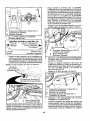
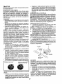
BLADE CARE
For best results mower blades must be
sharp. Replace worn, bent or damaged
blades.
A CAUTION: Use only a replacement
blade approved by the manufacturer of
your tractor. Using a blade not approved
by the manufacturer of your tractor is
hazardous, could damag e your tractor and
void your warranty.
.....
BLADE REMOVAL
1. Raise mower to highest position to allow
access to blades.
NOTE: Protect your hands with gloves and/
or wrap blade with heavy cloth.
2. Remove blade bolt by turning counterclockwise,
3. lnstallnewbladewith stamped "THISSIDE
UP" facing deck and mandrel assembly.
IMPORTANT: To ensure proper assembly,
center hole in blade must align with star on
mandrel assembly.
4. Install and tighten blade bolt securely
(45-55 Ft. Lbs. torque).
IMPORTANT: Special blade bolt is heat
treated.
Mandrel
Assembly
""_"_lt_
._--_,. _- Sta r
Center H ole-""_
,J_'_
_
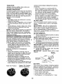
BATTERY
Your tractor has a battery charging system
which is sufficient for normal use. However,
periodic charging of the battery with an automotive charger will extend its life.
o Keep battery and terminals clean.
• Keep battery bolts tight.
• Keep small vent holes open,
• Recharge at 6-10 amperes for 1 hour.
NOTE:
Theoriginal
equipment
battery
on NOTE: Although multi-viscosity oils
yourtractoris maintenance
free,Donot (5W30, 10W30 etc.) improve starting in
attempt
toopenorremove
capsorcovers.cold weather, they will result in increased
Addingorchecking
levelof electrolyte is oil consumption when used above 32°E
not necessary.
Check your engine oil level more frequently to avoid possible engine damage from
TO CLEAN BATTERY AND TERMINALS
running low on oil.
Corrosion and dirt on the battery and termiChange the oil after even] 50 hours of opnals can cause the battery to "leak" power.
eration or at least once a year if the tractor
1. Remove terminal guard.
is not used for 50 hours in one year.
2, Disconnect BLACK battery cable first
Check the crankcase oil level before
then RED battery cable and remove
starting the engine and after each eight
battery from tractor.
(8) hours of operation. Tighten oil fill cap/
3. Rinsethe batten]with plainwaterand dry. dipstick securely each time you check the
4. Clean terminals and battery cable ends
oil level.
with wire brush until bright.
TO CHANGE ENGINE OIL
5, Coat terminals with grease or petroleum
Determine temperature range expected
jelly.
before oil change. All oil must meet API
6. Reinstall battery (See "REPLACING
service classification SG-SL.
BATTERY" in the SERVICE AND ADJUSTMENTS section of this manual).
• Be sure tractor is on level surface.
...........TRANSAXLE MAINTENANCE
° 0il will drain more freely when warm.
The transmission fan and cooling fins should
Catch oil in a suitable container,
be kept clean to assure proper cooling. Do
not attempt to clean fan or transmission while
1. Remove oil fill cap/dipstick, Be careful
engine is running or while the transmission
not to allow dirt to enter the engine when
is hot. To prevent possible damage to seals,
changing oil.
do not use high pressure water or steam to
2. Slideoil drain extensionfromthe docking
clean transaxle.
position on the engine blower housing
• Inspect cooling fan to be sure fan blades
and extend outward from engine,
are intact and clean.
• 1nspect cooling fins for dirt, grass clippings
pDo°Ck!ng
Oil Drain
SIIIOB
and other materials. To preventdamageto
seals, do not use compressed air or high
pressure sprayer to clean cooling fins.
TRANSAXLE PUMP FLUID
The transaxle was sealed at the factory and
fluid maintenance is not required for the life
of the transaxle. Should the transaxle ever
leak or require servicing, contact your nearest Sears or other qualified service center.
V-BELTS
3. To open,
counter-clockwise
CheckV-belts fordeterioration andwear after
. twist cap
,
4 After o I "s ...............................
dra ned completely, replace
-100 Hoursof 0peratiC)n_nd replaceif neces_..................
san). The belts are not adjustable. Replace
cap and twist clockwise until it stops.
5. Re-attach oil drain extension to engine
belts if they begin to slip from wear.
blower housing.
ENGINE
6. Refill enginewith oil through oil fill dipstick
LUBRICATION
tube. Pour slowly, Do not overfill, For apOnly use high quality detergentoil rated
proximate capacity see "PRODUCT SPwith APi service classification SG-SL.
ECIFICATIONS" section of this manual.
Select the oi!'s SAE viscosity grade
7, Use gauge on oil fill cap/dipstick for
according to your expected operating
checking level, For accurate reading,
temperature,
tighten dipstick cap securely onto the
tube before removing dipstick, Keep oil
at "FULL' line on dipstick. Tighten cap
onto the tube securely when finished.
23
ENGINE OIL FILTER
Replace the engine oil fflter every season or
every other oil change if the tractor is used
more than I00 hours in one year,
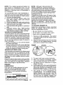
AIR FILTER
Your engine will not run properly usinga
dirty air filter. Clean the foam pre-cfeaner
after every 25 hours of operation or every
season. Service paper cartridge every
100 hours of operation or every season,
whichever occurs first.
Service air cleaner more often under dusty
conditions.
1. Remove cover.
CLEAN AIR SCREEN
Air screen must bekeptfree ofdirt and chaff
to prevent engine damage from overheating.
Clean with awire brush or compressed airto
remove dirt and stubborn dried gum fibers.
CLEAN AIR INTAKE/COOLING AREAS
To ensure proper cooling, make sure the
grass screen, cooling fins, and other external surfaces of the engine are kept clean
at all times.
Every 100 hours of operation (more often
under extremely dusty, dirty conditions),
removethe blower housing and other cooling
shrouds. Clean the cooling fins and external
surfaces asnecessary. Make surethe cooling
shrouds are reinstalled.
NOTE: Operatingthe engine with ablocked
grass screen, dirty or plugged cooling fins,
and/or cooling shrouds removed will cause
engine damage due to overheating.
MUFFLER
inspect and replace corroded muffler and
spark arrester (ifequipped) as it could create
a fire hazard and/or damage.
SPARK PLUG(S)
Replace spark plug(s) at the beginning of
each mowing season or after every 100
hours of operation, whichever occurs first.
Spark plug type and gap setting are shown
in "PRODUCT SPECIFICATIONS" section
of this manual.
TO SERVICE PRE-CLEANER
2. Wash it in liquiddetergent and water.
3. Squeeze it dry in a clean cloth.
4. Saturate it in engine oil, Wrap it in
clean, absorbent cloth and squeeze to
remove excess oil.
NOTE: If very dirty or damaged, replace
pre-cleaner.
TO SERVICE CARTRIDGE
1. Clean cartridge by tapping gently on
flat surface. If very dirty or damaged,
replace cartridge.
2. Reinstall precleaner cartridge, cover
and secure.
IMPORTANT: Petroleum solvents, such
as kerosene, are not to be used to clean
the cartridge, They may cause deterioration of the cartridge. Do not oil cartridge.
Do not use pressurized air to clean or dry
cartridge.
IN-LINE
FUEL FILTER
The fuel filter should be replaced once each
season.
If fuel filter becomes clogged, obstructing fuel flowto carburetor, replacement
is required.
1. With engine cool, remove filter and plug
fuel line sections.
2.
Place new fuel filter in position in fuel line
with arrow pointing towards carburetor.
3. Be sure there are no fuel line leaks and
clamps are properly positioned.
4. immediatelywipe
upanyspilled gasoline.
_
Cartridge
Clam____amp
Fuel Filter ---.---__
Foam
_
Pre-Cleaner__
24
CLEANING
• Clean engine, battery, seat, finish, etc.
of all foreign matter.
o Clean debris from steering plate.
Debris can restrict clutch!brake pedal
shaft movement, causing belt slip and
loss of drive.
Nozzle
Washout Port
_t, CAUTION: Avoid all pinch points and
movable parts
Clutch/brake pedal
Clean
!i
top side
IMPORTANT: Tug hose ensuring connection is secure,
5. Turn the water on.
6, While sitting in the operator's position
on the tractor, re-start the engine and
place the throttle lever in the Fast "._
position,
I;
Steering
Steering System, Dash,
Fender and Mower _ot Shown
UTION:
certain the area is clear. the area making
IMPORTANT:Recheck
7. Move the tractor's attachment clutch
control to the "ENGAGED" position.
Remain in the operator's position
with the cutting deck engaged until the
deck is cleaned,
& Move the tractor's attachment clutch
control to the "DISENGAGED" position. Turn the ignition key to the STOP
position to turn the tractor's engine off.
Turn the water off.
9. Pull back the lock collar of the nozzle
adapter to disconnect the adapter from
the nozzle washout port.
10. Move the tractor to a dry area, preferably a concrete or paved area. Place
the attachment clutch control in the
"ENGAGED" position to remove excess
water and to help dry before putting the
tractor away.
_kWARNING: A brokenor missingwashout
=fitting__u[d=exp_qsey_uor othersto thrown
objectsfrom contactwiil_-tlle-51acl_;
• Replacebrokenor missingwashoutfitting
immediately,priorto usingmower again.
• Plug any holes in mower with bolts and
Iocknuts.
•
Keep finished surfaces and wheels
free of all gasoline, oil, etc.
• Protect painted surfaces with automotive type wax.
We do not recommend using a garden hose
or pressure washer to clean your tractor
unless the engine and transmission are
covered to keep water out. Water in engine
or transmission wilt shorten the useful life of
your tractor. Use compressed air or a leaf
blower to remove grass, leaves and trash
from tractor and mower.
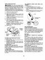
DECK WASHOUT PORT
Your tractor's deck is equipped with a
washout port on its surface as part of its
deck wash system. It should be utilized after each use,
1, Drive the tractor to a level, clear spot
on your lawn, near enough to a water
spigot foryour garden hose to-reach.
IMPORTANT" Make certain the tractor's
discharge chute is directed AWAY from your
house, garage, parked cars, etc. Remove
bagger chute or mulch cover if attached,
2. Make surethe attachment clutch control
is in the "DISENGAGED" position, set
the parking brake, and stop the engine.
3. Thread the nozzle adapter Ipackaged
with your tractor s Operator s Manual)
• onto the end of your garden hose.
4. Pull back the lock collar of the nozzle
adapter and push the adapter onto the
deck washout port at the left end of the
mower deck. Release the lock collar to
lock the adapter on the nozzle.
25
_
1.
3.
4.
5.
6.
ARNING: TO
ADJUSTMENTS:
AVOIDSERIOUSINJURY,BEFOREPERFORMINGANY SERVICEOR
Depress clutch/brake pedal fully and set parking brake.
Place attachment clutch in "DISENGAGED" position.
Turn ignition key to "STOP" and remove key,
Make sure the blades and all moving parts have completely stopped,
Disconnect spark plug wire from spark plug and place wire where it cannot come
in contact with plug,
TO REMOVE MOWER
1. Place attachment clutch in "DISENGAGED" position.
2. Lower attachment lift to lowest position,
3. Disengage belttension rod (K) from lock
bracket (L).
• ILCAUTION: Rod is spring loaded. Have a
tight grip on rod and release siowly.
4. Remove mower belt from electric clutch
pulley (M).
5. Disconnect front link (E) from mower remove retainer spring and washer,
6. Go to either side of mower and disconnect mower suspension arm (A) from
chassis and rear lift link (C) from rear
mower bracket (D) - remove retainer
springs and washers.
®
26
7. Go to other side of mower and disconnect
_tthe suspension arm and rear lift Iink.
CAUTION: After rear lift links are disconnected, the attachment iiftleverwillbe spring
loaded. Have a tight grip on lift lever when
changing position of the lever.
8. From right side of mower, disconnect
anti-sway bar (S) from right rear mower
bracket (D) - remove retainer Spring and
washer and pull mower toward you until
the bar falls from the hole in bracket.
9. Turn tractor steering wheel to the left as
far as it wi[i go.
10. Slide mower out from under right side of
tractor.
TO INSTALL MOWER
Follow procedure described in"TO 1NSTALL
MOWER" in the Assembly section of this
manual.
TO LEVEL MOWER
Make sure tires are properly inflated to the
PSI shown on tires. Iftires are over or under
inflated, it may affect the appearance ofyour
lawn and lead you to think the mower is not
adjusted properly.
VISUAL SIDE-TO-SIDE ADJUSTMENT
1. With all tires properly inflated and if your
lawn appears unevenly cut, determine
which side of mower is cutting lower.
NOTE: As desired, you can raise the low
side of mower or lower the high side.
2. Go to side of mower you wish to adjust.
3. With a 3/4" or adjustable wrench, turn
lift link adjustment nut (A) to the left to
lower the mower, or, to the right to raise
the mower,
4. If adjustment is necessary, see steps 2
and 3 in Visual Adjustment instructions
above,
5. Recheck measurements, adjust if necessary until both sides are equal.
FRONT-TO-BACK ADJUSTMENT
IMPORTANT: Deck must be level sideto-side.
Toobtain the best cutting results, the mower
blades should be adjusted so the front tip is
118"to 1/2" lower than the rear tip when the
ower is in its highest position.
CAUTION: Blades are sharp. Protect
your hands with groves and/or wrap blade
with heavy cloth.
° Raise mower to highest position.
• Position any blade so the tip is pointing
straight forward. Measure distance (B) to
the ground at front and reartipofthe blade.
o_
Turn nut left
lower mower
Turn nut righ
to raise mower
o o
• Iffronttip
of blade is not t/8"to 1/2" lower
than the rear tip, go to the front of tractor.
• With an 11/16" or adjustable
wrench,
loosen jam nut A several turns to clear
adjustment nut B.
• With a 3/4" or adjustable wrench, turn
front link adjustment
nut (B) clockwise
(ltighten) to raise the front of mower, or,
counterclockwise
(loosen) to lower the
front mower.
NOTE: Each full turn of adjustment nut will
change mower height about 3/16".
4. Test your adjustment by mowing some
uncut grass and visually checking the
appearance. Readjust, if necessary, until
you are satisfied with the results,
PRECISION SIDE-TO-SIDE ADJUSTMENT
1. Wit5 alltires properly inflated_park tractor _
on level ground or driveway.
CAUTION: Blades are sharp. Protect
your hands with gloves and/or wrap blade
Tighten adjust nut
Loosen adjust
with heavy cloth,
B to raise mower
nut B to lower
mower
2. Raise mower to its highest position.
3. At both sides of mower, position blade at
Loosenjamnut A first
side and measure the distance (A) from
bottom edge of blade to the ground. The
NOTE: Each full turn ofthe adjustment nut
distanceshould bethesameon both sides. will change mower height about 1/8".
• Recheck measurements, adjust if necessary until front tip of blade is 1/8" to 1/2"
lower than the rear tip.
• Hold adjustment nut in position withwrench
and tighten jam nut securely against adjustment nut.
27
Ai
,i
lA
TO REPLACE MOWER DRIVE BELT
MOWER DRIVE BELT REMOVAL
1, Park tractor on a level surface. Engage
parking brake.
2. Lower attachment lift lever to its lowest
position,
3. Disengage belttension rod (K) from lock
A bracket (L).
14_CAUTION: Belttension rod isspring loaded, Have a firm grip on rod and release slowly.
4. Remove screws (P) from R,H. and L,H.
mandrel covers and remove covers (Q).
5, Remove any dirt or grass clippings which
may have accumulated around mandrels
and entire upper deck surface.
6. Remove belt from electric clutch pulley
(M),both mandrel pulleys (R) and all idler
pulleys (S).
MOWER DRIVE BELT INSTALLATION
1. Install belt around both mandrel pulleys
(R) andaround idlerpulleys (S) as shown.
2. Instal]belt onto electric clutch pulley (M).
IMPORTANT: Check belt for proper routing
in all mower pulley grooves.
3. Reassemble R.H. and L,H. mandrel covers (Q). Securely tighten a_lscrews.
4. Engage belt tension rod (K) on locking
bracket{L).
_(t_CAUTION:Belt tension rod isspring loaded. Haveatight grip on rod andengage stow_y,
5. Raise attachment lift lever to highest
position,
BELT REMOVAL 1. Remove mower (See "TO REMOVE
MOWER" in this section of manual).
NOTE: Observe entire motion drive belt
and position of all belt guides and keepers.
2. Disconnect clutchwire harness (A).
3, Remove anti-rotation link (B) on right
side of tractor.
4. Remove belt from stationary idler (C)
and clutching idler (D).
5, Remove belt from centerspan idler (E).
6. Pull belt slack toward rear of tractor,
Carefully remove belt upwards from
transmission input pulley and over cooling fan blades (F),
7, Remove belt downward from engine
pulley and around electric clutch((3).
8. Slide belt toward rear of tractor, off the
steering plate(H) andremc_¢efromtractor.
BELT INSTALLATION 1. Install new belt from tractor rear to front,
over the steering plate (H) and above
clutch brake pedal shaft (J).
2. Pull belttowardfrontoftractorand rol]belt
around electric clutch and onto engine
pulley (G).
3. Pu]l belt toward rear of tractor, Carefully
work belt down around transmission
cooling fan and onto the input pulley (F}.
Be sure belt is inside the belt keeper.
4. Install belt on centerspan idler (E).
5, Install belt through stationary idler (C)
and clutching idler (D).
6. Reinstall anti-rotation link (B) on right
side of tractor. Tighten securely.
7. Reconnect clutch harness (A).
8, Make sure belt is in all pulley grooves
and inside all belt guides and keepers.
9. Install mower (See "TO INSTALL MOWER" in this section of manual),
TO REPLACE MOTION DRIVE BELT
Park the tractor on level surface, Engage
parking brake. For assistance, there is a
be_tinstallation guide decal on bottom side
of left footrest,
28
TO CHECK BRAKE
If tractor requires more than five (5) feet to
stop at highest speed in highest gear on a
level, dry concrete or paved surface, then
brake must be serviced.
You may also check brake by:
1. Park tractor on a level, dry concrete or
paved surface, depress brake pedal all
the way down and engage parking brake.
2. Disengage transmission by placing
freewheel control in "transmission disengaged" position, Pull freewheel control
out and into the slot and release so it is
held in the disengaged position.
The rear wheels must lock and skid when
you try to manually push the tractor forward.
If the rear wheels rotate, then the brake
needs to be serviced. Contact a Sears or
other qualified service center.
FRONT WHEEL TOE-IN!CAMBER
Your newtractor front wheel toe-in and cambet is set at the factory and is normal. The
front wheel toe-in and camber are not adjustable. If damage has occurred to affect the
factory set front wheel toe-in or camber, contact aSears or other qualified service center.
TO REMOVE WHEEL FOR REPAIRS
1. Block up axle securely.
2. Remove axle cover, retaining ring and
washers to allow wheel removal (rear
wheels have a square key - Do not lose),
3, Repair tire and reassemble.
NOTE: On rearwheets only: align grooves in
rear wheel hub and axle. Insert square key.
4. Replace washers and snap retaining ring
securely in axle groove.
5. Replace axle cover.
NOTE: To seal tire punctures and prevent
flat tires due to slow leaks, purchase and
use tire sealantfrom Sears. Tire sealant also
prevents tire dry rot and corrosion,
TO START ENGINE WITH A WEAK BATTERY
,/kWARNING: Lead-acid batteries generate explosive gases. Keep sparks, flame
and smoking materials away from batteries.
Always wear eye protection when around
batteries.
Ifyourbattery istooweakto startthe engine, it
should be recharged. (See"BA-FI'ERY" inthe
MAINTENANCE section of this manual).
If "jumper cables" are used for emergency
starting, follow this procedure:
IMPORTANT: Your tractor is equipped with
a 12 volt system, The other vehicle must also
be a 12 volt system. Do not use your tractor
battery to start other vehicles.
TO ATTACH JUMPER CABLES
1. Connectone end ofthe RED cable to the
POSITIVE (+) terminal of each battery(AB),taking care notto short against tractor
chassis.
2. Connect one end of the BLACK cable
to the NEGATIVE (-) terminal (C) of fully
charged battery.
3. Connect the other end of the BLACK
cable (D) to good chassis ground, away
from fuel tank and battery.
TO REMOVE
CABLES,
REVERSE
ORDER
t, BLACK cable first from chassis and then
from the fully charged battery.
2. RED cable last from both batteries.
.Weak orDead
Battery
Washers
Retaining
Ring
Axle Cover
'_._Square
Key (Rear
Wheel Only)
29
_Eully..Cha[ge_d_
Battery
REPLACING BATTERY
TO REMOVE HOOD AND GRILL ASSEMBLY
1. Raise hood.
2, Unsnap headlight wire connector.
3. Stand in front of tractor. Grasp hood at
sides, tilt toward engine and lift off of
tractor.
4. When replacing hood, be sure to reconnect the headlight wire connector.
n_asWARNING: Do not short battery termly allowing awrench or any otherobject
to contact both terminals at the same time.
Before connecting battery, remove metal
bracelets, wristwatch bands, rings, etc.
Positive terminal must be connected first to
prevent sparking from accidental grounding.
1. Lift hood to raised position.
2. Remove terminal cover.
3. Disconnect BLACK battery cable then
RED battery cable and carefully remove
battery from tractor,
4. Install new battery with terminals insame
position as old battery.
5. Reinstall terminal cover.
Hood
Headlight Wire
Connector
6. First connect RED battery cable to positive (+) battery terminal with bolt and nut
as shown. Tighten securely.
7. Connect BLACK grounding cable to
negative (-) batteryterminal with remaining bolt and nut. Tighten securely
8. Close hood.
TRANSMISSION
REMOVAL/REPLACEMENT
Should your transmission require removalfor
service or replacement, it should be purged
after reinstallation and before operating the
tractor, See "PURGE TRANSMISSION" in
the Operation section of this manual.
ENGINE
TO ADJUST THROTTLE CONTROL
CAB LE
The throttle control has been preset at
TO REPLACE HEADLIGHT BULB
the factory and adjustment should not be
1, Raise hood,
necessary Check adjustment as described
2. Remove bulb holderfrom the hole inthe
below before loosening cable. If adjustment
is necessary, see engine manual.
backside of the grill.
3. _Rep!afieI_u!b.!_3ho!de_ arid ir_sta[!.__bu!_b
..... TO ADJUST CHOKE CONTROL
holder securely back into the hole inthe
Ine cnol{e control has been preset at
backside of the grill.
the factory and adjustment should not be
4, Close hood.
necessary, If adjustment is necessary, see
INTERLOCKS AND RELAYS
engine manual.
TO ADJUST CARBURETOR
Loose or damaged wiring may cause your
tractor to run poorly, stop running, or prevent
Yourcarburetor has been presetatthefactory
it from starting.
and adjustment should not be necessary,
• Check wiring.
However, minor adjustment may be required
TO REPLACE FUSE
to compensate for differences in fuel, temperature, altitude or load. Ifthe engine does
Replace with 30 amp automotive-type plugin fuse. The fuse holder is located behind
need adjustment, see engine manual,
the dash.
3O
Immediately prepare your tractorfor storage
at the end of the season or if the tractor will
not be used for 30 days or more.
_IbWARNING: Never store the tractor with
gasoline in the tank inside a building where
fumes may reach an open flame or spark.
Allow the engine to cool before storing in
any enclosure.
TRACTOR
Remove mower from tractor for winter
storage. When mower is to be stored for a
period of time, clean it thoroughly, remove
all dirt, grease, leaves, etc. Store ina clean,
dry area.
1. Clean entire tractor (See "CLEANING"
in the Maintenance section of this
manual),
2. Inspect and replace belts, if necessary
(See belt replacement instructions inthe
Service and Adjustments section of this
manual).
3. Lubricate as shown in the Maintenance
section of this manual.
4, Be sure that all nuts, bolts and screws
are securely fastened, inspect moving
parts for damage, breakage and wear.
Replace if necessary.
5. Touch up all rusted or chipped paint
surfaces; sand lightly before painting.
BATTERY
• Fully charge the battery for storage.
° After a period of time in storage, battery
may require recharging.
• To help prevent corrosion and power leakage during long periods of storage, battery
cables should be disconnected and battery cleaned thoroughly (see "TO CLEAN
BATTERY AND TERM]NALSSin..the
Maintenance section of this manual).
• After cleaning, leave cables disconnected
and place cables where they cannot come
in contact with battery terminals,
• If battery is removed from tractor for
storage, do not store battery directly on
concrete or damp surfaces.
31
ENGINE
FUEL SYSTEM
IMPORTANT: It is important to prevent
gum deposits from forming in essential fuel
system parts such as carburetor, fuel hose,
ortank during storage. Also, alcohol blended
fuels (called gasohol or using ethanol or
methanol) can attract moisture which leads
to separation and formation of acids during
storage. Acidic gas can damage the fuel
system of an engine while in storage.
• Empty the fueltank by starting the engine
and letting it run until the fuel lines and
carburetor are empty.
• Never use engine or carburetor cleaner
products in the fuel tank or permanent
damage may occur,
• Use fresh fuel next season.
NOTE: Fuel stabilizer is an acceptable alternative in minimizing the formation of fuel
gum deposits during storage. Add stabilizer
to gasoline infuel tank or storage container.
Always followthe mix ratio found on stabilizer
container, Run engine at least 10 minutes
afteradding stabilizerto allowthe stabilizer to
reach the carburetor. Do not empty the gas
tank and carburetor if using fuel stabilizer.
ENGINE OIL
Drain oil (with engine warm) and replace
with clean engine oil. (See "ENGINE" in the
Maintenance section of this manual).
CYLINDER(S)
I. Remove spark plug(s),
2. Pour one ounce of oil through spark plug
hole(s) into cylinder(s),
3. Turn ignition keyto "START" position for
a few seconds to distribute oil.
4. Replace with new spark plug(s).
OTHER
• Do not store gasoline from one season to
another.
• Replace your gasoline can ifyour can starts
to rust. Rust and!or dirt in your gasoline
will cause problems.
° If possible, store your tractor indoors and
cover it to give protection from dust and dirt.
• Cover your tractor with a suitable protective cover that does not retain moisture.
Do not use plastic. Plastic cannot breathe
which allows condensation to form and wilt
cause your tractor to rust,
IMPORTANT:
Never cover tractor while
engine and exhaust areas are still warm,
TROUBLESHOOTING CHART:
See appropriate section in manual unless directed to Sears service center
CAUSE
PROBLEM
Will not start
Hard to start
Engine will not
turn over
Engine clicks but
wil/not start
CORRECTION
t
Out of fuel.
1
Fill fuel tank.
2
Engine not "CHOKED"
2
See "TO START ENGINE" in
Operation section.
3
Engine flooded.
3
Wait several minutes before
attempting to start.
4
Bad spark plug.
4
Replace spark plug.
5
Dirty air filter.
5
Clean/replace
6
Dirty fuel filter.
6
Replace fuel filter.
7
Water in fuel.
7
Empty fuel tank and carburetor.
refill tank with fresh gasoline and
replace fuel filter.
8
Loose or damaged wiring.
8
Check all wiring.
9
Carburetor
g
See "To Adjust Carburetor" in
Service and Adjustment s sect'ion.
10
Engine valves out of adjustment.
properly.
out of adjustment,
air filter.
101 Contact a Sears or other qualified
service center.
1
Dirty air filter.
2
Bad spark plug.
1
3
Weak or dead battery.
3
Recharge
4
Dirty fuel filter.
4
Replace fuel filter.
5
Stale or dirty" fuel.
5
Empty fuet tank and refill tank wilt
fresh, clean gasol{ne.
6
Check al_ wiring.
!2
Clean/replace
air filter.
Replace spark plug.
or replace battery.
6
LOose or damaged wiring.
7
Carburetor
8
Engine valves out of adjustment.
1
Clutch/13rake pedal not depressed. 1 1
Depress cinch/brake
2
Attachment
2
Disengage
3
Weak or dead battery.
3
Recharge or replace battery.
4
Blown fuse.
5
Corroded batlery termirrals.
5
6
Loose or damaged wiring.
' 6
7
Faulty ignition switch.
8
Faulty solenoid or starter.
9
Faulty operator presence
switch(es),
t
Weak or dead battery.
1
Recharge or replace battery.
2
Corroded battery terminals.
2
C{ean battery terminals.
3
Loose or damaged wiring.
3 _Chock all wiring.
4
Faulty solenoid or starter.
4
out of adjustment.
clutch is engaged.
I7
See 'q'o Adjust Carburetor" in
Service and Adjustments section.
8
Contact a Sears or other qualified
service center.
.4=
32
pedal.
attachment
clutch.
Repla_ef'4SCL
Clean battery terminals.
Check all wiring.
7
Check/replace
ignition switch.
8
Check/replace
solenoid or starter.
,9
Contact a Sears or other qualified
service center.
ChocWropiace
solenoid or starter.
TROUBLESHOOTING CHART:
See appropriate section in manual unless directed to Sears service center
pRO EM
,
CAUSE
Loss of power
CORRECT,O.
1
Cutting too much grass_too fast.
1
Raise cutting height/reduce
2
Throttle
position.
2
Adjust throttle control
3
Build-up of grass, leaves and
trash under mower,
3
Clean underside
housing.
4
Dirty air fitter.
4
Clean/replace
5
Low oil level/dirty oil.
5
Check oil level/change
6
Faulty spark plug.
i 6
CIean®aporchangesparkplug,
7
Dirty fuel filter,
i 7
Replace fuel filter.
8
Stale or dirty fuel.
8
Empty fuel tank and refill tank with
fresh, clean gasoline.
9
Water in fuel.
9
Empty fuel tank and carburetor,
efill tank with fresh gasoline and
replace fuel filter.
10
Spark plug wire loose,
10
11
Dirty engine air screen!fins.
111 Clean engine air screen/fins.
12
Dirty!clogged
12. Clean/replace muffler.
13
Loose or damaged wiring.
13
Check all wiring,
14
Carburetor
14
Bee "To Adjust Carburetor" in
Service and Adjustments section.
15
Engine valves out of adjustment.
15
Contact a Bears or other qualified
service center.
in "CHOKE"
muffler.
out of adjustment.
of mower
air filter.
oil,
Connect & tighten spark plug wire,
.... ,........
,,,,_H,
1
Worn, bent or loose blade.
1
Replace blade. Tighten blade bolt
2
Bent blade mandrel.
2
Contact a Bears or other qualified
service center,
3
Tighten loose part(s).
Replace damaged parts.
1
Check wiring, switches and
connections. If not corrected,
contact a Bears or other
1
Replace blade. Tighten blade bolt
=3
Loose!damaged
part(s).
,, ,,,,
,, ,,,,
Engine continues
to
run when operator
leaves seat with attachment clutch engaged
t
Faulty operator-safety
control system,
presence
1
Worn, bent or loose blade.
2
Mower deck not level
2
Level mower deck,
3
Buildup of grass, leaves, and
trash under mower,
3
Clean underside of mower
housing.
4
Bent blade mandrel.
4
Contact a Bears or other
qualified service center.
5
Clogged mower deck vent from
build-up of grass, leaves, and
trash around mandrels.
5
Clean around mandrels
open vent holes.
1
Obstruction
1
Remove obstruction.
2
Worn/damaged
3
Frozen idler pulley.
3
Replace idler pulley.
4
Frozen blade mandrel.
4
Contact a Sears or other
qualified service center.
,,,
Poor cut - uneven
i-cutting
Mower blades
not rotate
will
speed.
,,,,,,,,,
=.
in clutch mechanism.
mower
33
drive belt, 2
to
Replace mower drive belt,
TROUBLESHOOTING CHART:
See appropriate section in manual unless directed to Sears service center
PROBLEM
CAUSE
Poor grass
discharge
Headlight(s)" not
working
(if so equipped)
Battery
charge
will not'
Loss of drive
Engine "backfires"
wnen turning
engine "OFF"
Erngine dies when
a_or is snir¢ea
into reverse
CORRECTION"
1
'Engine speed too slew.
1
Place throttle control in "FAST '_
position.
2
Travel speed too fast,
2
Shift to slower speed,
3
Wet grass.
3
Allow grass to dry before mowinc
4
Mower deck not leve!.
4
Level mower deck,
5
Low/uneven tire air pressure.
5
Check tires for proper PSI,
6
Worn. bent or loose blade.
6
Replace/sharpen
blade bolt.
7
Buildup of grass, leaves and
trash under mower.
_7
Clean underside
housing.
8
Mower drive belt worn.
8
Replace mower drive belt.
9
Blades improperly
9
Reinstall blades sharp edge dowr
installed,
10
blade. Tighten
of mower
t0
Improper blades used.
11
Clogged mower deck vent holes
11
from buildup of grass, leaves, and
trash around mandrels.
Clean around mandrels to
open vent holes.
1
Light switch is "OFF".
1
Turn light switch "ON",
2
Bulb(s) or lamp(s) burned out.
2
Replace bulb(s) or lamp(s),
3
Fault,i light switch,
3
Check/replace
4
Loose or damaged wiring.
4
Check wiring and connections,
5
Blown fuse,
5
Replace fuse.
Rep ace w th b aries listed {n
this manual,
]ight switch,
1
Bad battery cel](s)i'
1
Replace battery.
2
Poor cable connections.
2
Check/clean
3
Faulty regulator
3
Replace regulator.
(if so equipped).
all connections.
4
Faulty alternator.
4
Replace alternator,
I
Freewheel control in
"DISENGAGED"
position.
1
Place freewheel control in
"ENGAGED" position.
2
Debds on steering plate (if
equipped),
2
See "CLEANING" in the
maintenance section.
3 " lvio[ion orlve oett worn. damaged.
or broken.
3
4
Air trapped in transmission
shipment or servicing.
4
5
AXle key missing.
lnstaII axle key at rear wheeI. See
"TO REMOVE WHEEL" in the
Service and Adjustments section.
Engine throttle control
not set 1
between half and fulI speed (fa_
position before stopping engine
Move throttle control between
half and full speed (fast) position
before stopping engine.
Reverse operation system (ROS)
is not "ON" while mower or other
attachment is engaged.
Turn ignition key to ROS "ON"
posffion, See Operation section.
1
1
34
during
1
Replace
motion drive belt,
Purge transmission.
TROUBLESHOOTING CHART:
See appropriate section in manual unless directed to Sears service center
NEED MORE HELP?
You'll find the answer and more on managemyhome,
- Find this and aLLyour other product manuals online.
" bet
answer5
T[Om
OUT
]_eam
01
nOrl|r_
_xp_ILS,
" Get a personafized maintenance ptan for your home,
" Find information and tools to help with home projects.
•
i
35
com-
for free!
SUGGESTED
GUIDE
FOR SIGHTING
SLOPES
ONLY RIDE UP AND DOWN
NOT ACROSS HILL
FOR SAFE OPERATION
HILL, I
15 DEGREES MAX.
WARNING:
TO avoid serious injury, operate your tractor up and
down
face of
slopes,
never across
the face.
Do nottomow
s_opesthe
greater
than
15 degrees,
Make turns
gradually
prevent
tipping or loss of control Exercise extreme caution when
changing direction on slopes.
1. Fold this page along dotted line indicated above.
2, Hold page before you so that its left edge is vertically parallel to a tree
trunk or other upr{ght structure.
3. Sight across the fold in the direction of hill slope you want to measure.
4. Compare the angle of the fold with the slope of the hill
Garantia ..........................................................
Reglas de Segur[dad ......................................
Espeoficaciones det Producto ........................
Montaje/Pre Operaci6n ...................................
Operaci6n .......................................................
Mantenimiento ................................................
87
38
41
42
48
56
Programa de Mantenirniento .......................... 56
Servicio y Ajustes ........................................... 61
Almacenamiento ............................................. 66
ldentfficaci6n de Problemas ........................... 67
Servicio Sears .................................. Oontratapa
Garantfa para equipos tractores Craftsman
GARANTiA COMPLETA DE CRAFTSMAN
PeR DOS AI;JOS desde la fecha de compra, redes las partes no sustitu[bles de este equipo tractor est__n
garantizades centre cualquier defecto de material o mane de obra. Una parte no sustituible defectuosa
recibird reparaci6n o reempfazo gratu[to encasa si la reparaci6n es imposible,
PeR CINCO AfJOS desde Ia fecha de compra, el bastidor y el eje delantero de este equipo tractor estbn
garantiZados centre cualquier defecto de materiat o mane de obra. Un bastidor o eje delantero defectuoso
recibir__ reparaci6n o reemplazo gratuito en case si la reparaci6n es imposible,
..............DURANTE 90 DiAS desde la fecha de compra, Ia bater_a (una parte sustituible) de este equipo tractor
est& garantizada centre cualquier defecto de material o mane de obra (nuestra prueba comprueba que no
contendr_, carga). Una bateria defectuosa recibir_, un reemptazo gratuito en case,
GARANTiA LIMITADA DE PeR VIDA ADICIONAL en el EJE DELANTERO
DE HIERRO COLADO (si
est& provisto)
DURANTE EL TIEMPO EN QUE SE USE per el propietario original despuds del quinto aSo a partir de la
fecha de compra, el eje delantero de hierro cotado (si est_ provisto) de este equipo tractos es_ garantizado
centre cualquier defecto de material o mane d8 obra. Con el comprobante de compra, un eje delantero de
hierro colado recibirfi un reemplazo gratuito encasa.
SERVICIO
DE GARANTiA
Pare conocer los detalles de ta cobertura de garantia pare obtener una reparaci6n o reemplazo gratuito,
llama al 1-800-659-5917
6 visite et sitio web: www. craflsman.com
En todos los cases anteriores, si el reemplazo es imposible, el equipo tractor ser& sustituido sin cargo con
el mismo modelo o uno equivalente.
Toda Ia cobertura de garant_a anterior ser& nula si este equipo tractor se utilize alguna vez pare brindar
servicios comerciales o sise alquila a otra persona.
Esta garantia cubra 0 N ICAMENTE defectos de material y mane de obra. La cobertura de garantia NO incluye:
• Partes sustituibles (excepto la bateda) qua se puedan desgastar per el use normal dentro del periodo de
garantia incluso, pete sin limitarse a, cuchillas, bujias, filtros de aire, correas y filtros de aceite.
• Servicios de mantenimiento est_ndar, camb[os de aceite o afinaciones.
•
Reemplazo o reparaci6n de neum&ticos per pinchazos causados per objetos exlernos come clavos,
espinas, tocones o vidrios.
,.-Reemplazo o reparaci6n de neum&ticos.o ruedas per deegaste n0rrnat, acc[den'_e.s o per ooeraciSn o
mantenimiento incorrectos.
• Reparaciones
necesarias per abuse del operador incluso, pore sin limitarse a, defies causados per
remolcar objetos que superen la capacidad del equipo tractor, chocar centre objetos qua doblen et
bastidor, el ensamble del eje o el ¢ig0efiaI o sobrepasar la velocidad del motor.
• Reparaciones necesarias per negligencia del operador, inctuso (pore sin limitarse a ello) daSos electricos
y mec,_nicos causados per el almecenamiento incorrecto, per no usar el grado y Ia cantidad correctos de
aceite de motor, per no mantener del muetla libra de residues [nflamables o per no mantener el equ[po
tractor de acuerdo con las instrucciones que contiene eL manual del operador,
•
Limpieza o reparaciones
de] motor (sistema de combustible) cuando se determina
que se us6
combustible contaminado y oxidado (sarro). En general, el combustible debe usarse dentro de toe 30
dias posteriores a su compra.
• Deterioro y desgaste normal de los acabados extedores o sustituci6n de r6tulos de productos.
Esta garantia le otorga detaches [egales especfficos, y usted tambi_n puede tenor otros derechos qua
varfan de un estado a otro.
Sears Brands Management Corporation,
Hoffman Estates, IL 60179
37
_PELIGRO:
Esta Maquina cortadora es capaz de amputar tas manosy los pies y de lanzar
objetos, si no se observan las |nstrucciones de seguridad siguientes se pueden producir
lesiones graves o la muerte.
• No maneje Ia m&quina si no tiene ta trampa
_ADVERTENCIA:
Siempredesconecteel alampara c_sped completa, la canaleta de descarga
bre de la bujia y p6ngalo donde no pueda entrar
u otros dispositivos de seguridad en su Iugar
en contacto con la buj{a, para evitar el arranque
y en funcionamiento.
por accidente, durante la preparaciSn, el trans• Ralentizar antes de girar.
porte, el ajuste o cuando se hacen reparaciones.
• Nunca dejar una m&quina encendida sin vigi_IiADVERTENCIA: Noavancecues1_abajo apunlancia. Apagar siempre las cuchillas, poner et
to muerto ya que podria pettier el control deItractor.
freno de estacionamiento, parar el motor, y
_iI_DVERTENCIA:
Remolque solamente los
quitar las Ilaves antes de bajar.
accesorios recomendados y conformes a Ias
• Desenganche las hojas cuando no est@cortancaracteristicas indicadas por et fabricante de su
do cespsd. Apague el motor y espere hasta que
tractor. Tenga cuidado y prudencia al utilizar el
todas Iaspartes se detengan pot completo antractor. Cuando se encuentre en un declive, oper
tes de limpiar la m&quina, retirar Iatrampa para
htilizando exclusivamente Iavelocidad m&s baja.
c_sped o destapar Ia canaleta de descarga.
En caso de un declive una carga excesiva po• Hacer funcionar la maquina sSIo con ta luz del
dria resultar peligrosa. Los neum&ticos pueden
d[a o luz artificial buena.
perder la tracci6n con el suelo y hacerle perder
No hacer funcionar Ia m,_quina estando bajo
el control de su tractor.
los efectos de alcohol o droga.
_DVERTENO1A:
El tubo de escape de1motor,
•Poner
atenci6n al trY.rico cuando se opera
cerca de calles o se cruzan.
algunos de sus constituyentes y algunos componentes deI vehiculo contienen o desprenden
• Poner la m&xima atenci6n a! cargar o descarproductos quimicos conocidos en el Estado de
gar Ia m&quina en una caravana o cami6n.
California como causa de c&ncer y defectos al
• Llevar siempre gafas de protecci6n cuando se
nacimiento u otros daSos reproductivos.
hace funcionar la m_.quina.
_t_DVERTENCIA:
Los bornes, terminales y ac• Los datos indican que los operadores a partir
cesorios relativos de la bateria contienen plomo
de los 60 a5os est&n afectados por un gran
o compuestos de plomo, productos qu{micos
porcentaje de heridas retativas a laconducci6n
conocidos en ef Estadode California como causa
del cortac6sped. Estos operadores tendrian
de c&ncer y defectos al nacimiento u otrosdaSos
que evaluar su habilidad de hacer funcionar
reproductivos. Lavar las manos despu@s de
el cortac_sped de modo Io bastante seguro
manipularlos.
para proteger a si mismos y a otras personas
de heridas graves.
i, FUNCIONAMIENTO
GENERAL
• Seguir las recomendaciones deI fabricante
• Leer, entender y seguir todas tas instrucciones
para los pesos y contrapesos de las ruedas.
sobre Ja m&quina y en el manual antes de
• Mantener ta m_.quina libra de hierba, hojas u
empezar.
otros escombros que pueden tocar el tubo de
• No poner las manos o tos pies cerca de partes
escape/partes del motor calientes y quemarse.
giratorias o debajo de la m&quina, mantener
No permitir que el puente del cortac_sped
siempre limpia la abertura de descarga.
cargue hojas u otros residuos que pueden
t ]_ermitirel funcionamiento de !a m_qu!na ,s6!o................
causar acurnulaciones. Limpiar toda saipica__
a adultos que tengan familiaridad con Ias
dura de aceite o carburante antes de hacer
instrucciones.
operaciones sobre Ja m_.quina o guardarla.
Dejarla enfriar antes de guardarla.
• Limpiar el drea de objetos como piedras,
juguetes, cables, etc. que pueden ser recogiII. FUNCIONAMIENTO
EN PENDIENTES
dos y disparados con las cuchillas.
Las pendientes son el mayor factor de accidentes
• Asegurarse de que el _.rea est@libre de otras
relativos a la p_rdida de control y vuelco, que
personas antes de ponerla en marcha. Parar
pueden causar severas heridas o muerte, El funla m__quinasi alguien entra en el &rea.
cionamientoen pendientes requiereuna atenci6n
° Nunca Ilevar pasajeros.
extra.Si no es posib[e hacer marcha atr_s en una
° No oortar marcha atr_.s al no set absolupendiente o si te sientes incomodo, no Ia cortes.
tamente necesario. Mirar siempre abajo y
• Cortar hacia ardba y abajo de una pendiente,
delante mientras se proeede atr&s.
no de modo horizontal.
- Nunca dirigir et material descargado hacia ha• Poner atenciones a los hoyos, Ias raices, los
die. Evitar descargar material contra paredes
bultos, Ias piedras u otros objetos escondidos.
u obstrucciones. El material podria rebotar
El terreno irregular puede votcar la m_.quina.
hacia el operador. Parar las cuchillas cuando
se pasan superficies de grava.
La hierba alta puede esconder obst_.culos.
38
• Escoger una velocidad de marcha baja de
mode que no sea necesario pararse o cambiar
estando en una pendiente.
• No cortar la hierba mojada. Las ruedas pueden
perder tracciSn.
Porter siempre una marcha cuando se est&
en pendientes. No poner en punto muerto e ir
cuesta abaje,
• Evitar arrancar, pararse o girar en una pendiento. Si Ins ruedas pierden tracci6n, desconectar
Ins cuchillas y preceder despacio cuesta abajo
en Ia pendiente.
• Mantener redo los movimientos en Ins pendientes Ientos y gradual. No hacer cambios
repentinos de velocidad o direcci6n, ya que
pueden causar el escape de ta m_.quina.
• Porter ta m&xima atenci6n cuando fa m&quina
funciona con captadores de hierba u otres
dispositivos enganchados; pueden afectar la
................estabilidad de Ia m&quina. No usar en pendi_
entes empinados.
• No intentar estabilizar la m&quina poniendo el
pie en el terreno.
• No cortar cerca de bajadas, cunetas y orillas,
Las m_quina puede volcarse improvisamente
si una rueda est& en el borde o se hunde.
ill. NINes
_,ADVERTENCIA:
LOS NIt'.4OS PUEDEN
SUFRIR DANES CON ELUSO DE ESTE EQUIPO, La Academia Estadounidense de Pediatrla
(American Academy of Pediatrics) recomienda
que s61o se permita a ni_os con una edad mfnima de 1 2 aries manejar m&quinas cortac@sped
manuales, y aI menos de !6 a_,os para manejar
tractores cortac_sped,
Si el operador no pone atenci6n a la presencia
de los nif_os pueden ocurrir accidentes tr&gicos,
Los nifios a menudo est_n atraidos per la maquinay Ias actividad de cortar. No dar per hecho
de que los nir_os se queden adonde estaban la
_ltima vez que los vistes.
• Mantener los ni_os fuera det &rea de corte y
.-v_giladosper un adulto responsabteque no sea
el operador.
• Estar alerta y apagar Ia maquina si un nifios
entra en el &rea.
o Antes y durante larnarcha atras, mirar adelante
y abajo para vet si hay nifios pequefios.
• Nunca Ilevar nifios, incluso si hay Ins cuchillas
apagadas. Podrian caer y herirse seriamente
o interferircon el funcionamiento seguro de Ia
rn&quina, los ni_os que se han Ilevado preco
edentemente pueden aparecer de pronto en el
_rea de corte per otro paseo y ser atropellados
o tumbados per fa m_.quina.
• Nunca dejar que los nifios manipulen Ia m&quina.
39
• Tenet el m_imo cuidado cuando se acerca
a cantos ciegos, arbustos, _.rboles u otros
objetos que pueden impedir la vista de niQos.
IV. REMOLQUE
• Remolcar s61o con una mdquinaquetenga un
gancho disefiado para remolcar. Enganchar el
equipo o remolcar s61o en el punto dispuesto
al efecto.
° Seguir Ins recomendaciones deI productor con
respecto a los limites del equipo per remolcar
y el remolque en pendientes.
• Nunca permitir que nifios u otras personas
est@ndentro del equipo per remolcar.
• En pendientes, el peso del equipo remolcado
puede causar la p_rdida de tracciSn y Ia p_rdida de control.
• V[ajar despacio y dejar m_.s distancia para
frenar.
V. SERVICIO
MANIPULACION SEGURA DE LA GASOLINA
Para evitar heridas personales o dafios a Ins
cosas, porter el m&ximo cuidado a la hera de
manipu[ar Ia gaso]ina. La gasolina es extremamonte inflamable y los vapores son explosives.
• Apagar todos los cigarrillos, cigarros, pipas y
otras fuentes de ignici6n.
• Usar s6]o contenedores para gasolina aprobados.
• Nunca quitar el tap6n de ]a gasolina o afiadir
carburante con el motor en marcha, dejar
enfriar el motor antes del abastecimiento de
Ia gasolina.
° Nunca abastecer Ia m_.quina al interior de un
local.
• Nunca guardar la m&quina o el contenedor
deI carburante donde haya una llama abierta,
chispas o una luz piloto come un calentador
de agua u otros dispositivos.
• Nunca llenar los contenedores at interior de
un veh[cuIo o en una caravana o camiSn
.recubiertos con un forro de pl&stico, Colocar
siempre los contenedores en el terreno Iejos
° Quitar eI equipo de gas del cami6n o caravana
y abastecedo en el terreno, Si no es posible,
abastecer dicho equipo con un contenedor pop
t&til, m&s bien que de un surtidor de gasolina.
- Mantener la boquilla a contacto del borde
del dep6sito de carburante o la abertura del
contenedor durante toda la operaci6n de
abastecimiento. No utilizar un dispositivo con
boquilla cerrada-abierta.
• Si se vierte carburante sobre la ropa, cambiarse la ropa inmediatamente.
° Nunca itenar el dep6sito m&s de 1o debido.
Volver a colocar el tap6n deI gas y cerrar de
mode firme.
OPERAC|ONES
DE SERV|C|O
GENERALES
• Nunca hacer funcionar Ia m&quina en un _rea
eerrada.
- Mantener todas lastuercas y pernos apretados
para asegurarse de que trabaja en condiciones
seguras.
• Nunca modificar los dispositivos de seguridad.
Controlar su correcto funcionamiento regularmente.
. Mantener la m&qu[na fibre de hierba, hojas
u otros residues acumulados. Limpiar Ias
salp[caduras de aceite o carburante y quitar
cualquier cosa mojada con carburante. Dejar
que la m&quina se enfrie antes de guardarla.
• Si se golpea un objeto ajeno, hay que pararse
e inspeccionar {a m_.quina. Reparar, si es
necesario, antes de velvet a porteren marcha.
• Nunca hacer ning_n ajuste o reparaci6n con
et motor en funciSn.
• Ve_ifique los componentes de la trampa para
c6sped y ta canaieta de descarga con frecuenciay Sust[tuya con repuestos recomendados
per eEfabricante cuando sea necesario.
• Las cuchiUas del cortac6sped son afiladas.
Envo[ver {a cuchilJa, ponerse guantes y porter
Ia m_xima atenci6n cuando se hacen operac{ones en elias.
• Controlar el funcionamiento del freno frecuent• Estar alerta y apagar Ia m__quinasi un nir_os
entra en el Area.
emente. Ajustar y hacer Ias operaciones de
mantenimiento cuando eso sea necesario,
• Antes y durante Jamarcha atr&s, mirar adelante
• Mantener y sustituir las etiquetas de seguridad
y abajo para vet si hay niffos pequefios,
e instrucci6n, cuando sea necesario.
• Cortar hacia arriba y abajo de una pendiente
(15° M_tx),no de mode horizontal.
• Asegurarse de que el _.rea est6 libre de otras
personas antes de poneda en marcha, para la
• Escoger una velocidad de marcha baja de
m&quina si alguien entra en el _,rea.
mode que no sea necesario pararse o cambiar
estando en una pendiente.
° Nunca I[evar pasajeros.
• No ¢ortar marcha atr&sal no set absolutamente
• Evitar arrancar, pararse o girar en una pendiennecesario. Mirar siempre abajo y delante
re. Si Ias ruedas pierden tracci6n, desconectar
mientras se precede atr&s.
las cuchillas y precederdespacio cuesta abajo
en la pendiente,
• Nunca llevar niSos, inciuso si hay las cuchillas
apagadas. Poddan caer y herirseseriamente
• Si Ia m_.quina se para mientras va cuesta
o interferir con el funcionamiento seguro de la
arriba, desconectar las cuchillas, poner ta
m_.quina, los nifios que se hart llevado precmarcha atr_.s y ir hacia atr&s despacio.
edentemente pueden aparecer de pronto en el
• No girar estando en pendientes si no es nece_,rea de corte per otro paseo y set atropellados
sario, y luego girar despacio y gradualmente
o tumbados per la m&quina.
cuesta abajo, si es posible.
--_-Manter_er los ni_os fuera del _,readecortey---;-_I_arg_,_6_ie_6argaf
l_ifi_quiiia_i_6_65i_iS_¢e ....
vigilados per un adulto responsableque no sea
el _ngulo m_iximo recomendado de 15°.
el operador.
4O
ESPECIFICACIONES DEL PRODUCTO
Capacidad y Tipo
de Gasoline:
3.0 Galones/11,35 L
Regular Sin Plomo
Tipo de Aceite
(API: SG-SL):
SAE 30 (sobre 32°F10°C)
SAESW30 (deabejo32°F/0°C)
Con Filtro: 64 Oz./1.96 L
Sin Filtro:
60 Ozj1,77 L
Capacidad de
Aceite:
Bujia
Champion QCt 2YC
(Abertura: ,040'71.02ram)
Sistema de
Carga:
Bateria:
16 Amps @ 3600 RPM
En el estado de California, ta ley exige Io anterior
(Secci6n 4442 deI "California Public Resources
Code"). Otros estados pueden center con otras
leyes parecidas. Las leyes federales se aplican
en latierras federates. Su centre de Servicio m&s
cercano tiene disponible amortiguadores de chispas pare el silenciador. (Vea la seccibn de Partes
de Repuesto en et manual Ingl6s det dueSo,)
ACUERDOS
DE PROTECClON
PARA
LA REPARAGI6N
Congratulaciones
per su buena compra. Su
nuevo producto Craftsman@ est& diseSado y
fabricado para funcionar de mode fiab[e per
touches aSos, Pero come todos los productos,
puede necesitar alguna reparaci6n de tanto en
lento. En este case tener un Acuerdo de Preteccidn para Ia Reparaci6n puede hacerles ahorrar
dinero y fastidies.
Cempre ahora un Acuerdo de Protecci6n para la
Reparaci6n y protL=gese de mo[estias y gastos
inesperados.
Un Acuerdo incluye los puntos siguientes:
Amp/Hr:
28
Min, CCA:
230
Modelo Tamaflo: UIR
Torsi6ndel Perno 45-55 Ft. LbsJ62-75 Nm
_e IaCu,_hilla:
,,
FELICITACIONES per la compra de su tractor. Ha
side diseSado, planificado yfabric,ado pare dade la
mejor conflabilidad yel meier rendimiento posible.
En el case de que se encuentre con cualquier
problema que no pueda solucionar f_.ci]mente
haga el favor de ponerse on contacto con un
centre de servicio Sears o con un otro centre de
servicio cualificado. Cuenta con representantes
bien capacitados y competentes y con las herramientas adecuadas pare darle servicio opara
reparar este tractor,
Haga el favor de leer y de guarder este manual.
Estas instruc-ciones le permitir&nreenter y mantener su ur_idad en forma adecuada. Siempre
observe las "REGLAS DE SEGURIDAD."
RESPONSABILIDADES
•
•
•
•
DEL CLIENTE
•
• Lea y observe las regIas de seguridad.
• Siga un programa regular de mantenimiento,
cuidado y use de su tractor,
- Siga las instrucciones descritas en [as secclones "Mantenimiento" y "Almacenamiento"
de este manual,
Servicio experto de nuestros 12.000 espec a stas profesiona[es en a reparac 6n.
Servicio ilimitado sin cargo alguno pare
las partes y la mane de obra sobre todas tas
reparaciones garantizadas,
Sustltuci6n
del producto si su producto
garantizade no puede ser arreglado.
Descuento de110% sobre el precio corriente
del servicio y de las parsesrelativas al servicio
no cubiertas per el acuerdo; tambi_n el 10%
menos sobre el precio corriente de un control
de mantenimiento preventive.
Ayudar_pidaportel_fo_o-eoportetelef6nico per parte de un representante Sears sobre
productos que requieren un arreglo en case, y
adem&s una programaci6n sobre los arreglos
m_,s convenientes.
Cuando se ha comprado el Acuerdo, basta con
unallamada telef6nica pare programar el servicio.
• Utilice prendas de seguridad adecuadas at
Puede Ilamar cuando quiera, die y noche o fijar
manejar la m&quina, incluidos (come m_nimo)
en linea una cita para obtener el servicio. Sears
calzado de seguridad, gafas protectoras y protiene m&s de t2.000 especialistas profesionales
tecci6n auditiva. No utilice pantalones cortes
en la reparac}dn, que tienen acceso a m_s de
yio calzado abierto cuando corte Ia hierba.
4.5 railleries de partes y accesorios de calidad,
__.j=nfomles.iemp[e a a!gu.ien de quese dispose ........E.§tees el tipo de profesionalidad con que puede
a cortar la hierba en e exterior,
center para_aysdar a alatgar la vide de[pfbducto que acaba de comprar, per touches aSos.
_I_ADVERTENCIA: Este tractor viene equipado
iCompre hey su Acuerdo de Protecci6n pare la
con un motor de combusti6n interne y no se debe
Reparaci6n!
user sobre, o cerca, do un terreno no desarrollado
cubierto de bosques, de arbustos o de c@sped, Se aplican algunas limitaciones y exclusiones.
Para conocer los precios y tenet mds Inforo menos que el sistema de escape det motor
macibn, game al 1-800-827-6655.
venga equipado con un amortiguador de chiepas
que cumpla con las Ieyes locales o estata[es (st
SERVICIO DE INSTALACtON
SEARS
existen). Si se usa un amortiguador de chispas,
el operador debe mantenerlo en condiciones de
Para /a insta!aci6n profesiona/ Sears de aparatrabajo ef_cientes.
toe de casa, puertas de garaje, calentadores de
agua y otros importantes articulos pare la case,
en U.S.A Ilamar a
1-800-4-MY-HOME®
41
,, ,,
illl i
Rueda
\
(5) 1-3/16"
Arandela
(1) 1-1/4"
Arandela
_'_
'_\.
(__
\_
(1) Eslabones
"_\
de levantamiento"_
_<_
delanteros "_
(5) Abrazadera
grande de retenci6n
i
iii
De La Segadora
(11 Perno
de ]evantamiento
traseros
(1) Abrazadera
peque_o de retenci6n
Delantera
(1)3/_.16(1) Rueda
Tuerca
i
Si Los Tiene
H
ll) Barra Antioscilacidn
(1) 3/4"
Arandela
Llaves
411111
(1) Abrazadera peque_o de retenci6n
ill
Hoja de pendiente
_l
*]nstalado por el
distribuidor
*Juego de cubierta
42
(2) Llaves
Su tractor nuevo hasido montado en la f&bdca con la excepci6n de aque[las partes que no se han montado per re.zones de envio. Para asegurarse que su tractor funcione en forma adecuada y segura todas
las partes y los articulos de ferreteria que se monten tienen que set apretados en forma segura, Use tas
herramientas correctas, seg_n sea necesado, para asegurarse de que est6n apretados en forma segura,
3.
HERRAMIENTAS
NECESARIAS
PARA
EL MONTAJE
Un juego de Ilaves de tube facilitar& el montaje.
A continuaci6n se enumeran los tamales de _as
lfaves est&ndar.
(2) Llaves de 7/16"
Cuchillo
(1) Llaves de 1/2"
Medidor de presibn
(1) Llave de 3/4"
Pinzas
(I) Montura de 3/4 pulg. con mando de trinquete
(1) LIaves de I/2"
Unterna
Cuando en este manual se mencionan los terminos"mano derecha" o "mane izquierda" se refiere a
cuando usted se encuentra en la posici6nde operacidn (sentado/a detr&s del volante de direcci6n).
Desconecte la palanca para trabar el asiento
en ]a posici6n.
AVISO: Ahora puede rodar su tractor fuera
de la corredera. Siga Ias siguientes instruc*
ciones para remover el tractor de Ia corredera.
_, ADVERTENCIA: Antes de empezar, leer,
entender y seguir todas las instrucciones presentes en la secci6n Operaciones de este manual,
Asegurarse que el tractor est_ en un &tea bien
ventilada. Asegurarse que la zona delante deI
tractor est6 Iibre de otras personas y objetos.
PARA REMOVER
EL TRACTOR
DE LA
CAJA DE CARTON
DESEMPAQUE LA CAJA DE CARTON
Remueva todas las partes sueltas que est_n
accesibles, y tas cajas de partes, de la caja
de cart6n grande.
• Cortar ale largo de IasIineas de puntos en todos
los cuatro paneles de cart6n. Remover los paneles de cierre y aplanar los paneleslaterales.
Remueva la segadora y los rnateriales del
embalage.
• Revise si hay partes sueltas adicionales o
cartSn y remu_valas.
ANTES DE REMOVER EL TRACTOR
DE
LA CORREDERA
VERIFIQUE LA BATERiA
1. Levante del capota a Ia posiciSn Ievantada
AVISO: Siesta bateda esta utilizada despu_sdef
mes y aSo indicado sobre ta etiqueta (la etiqueta
que se encuentra entre losterrninales), cargue la
bateria per un minimo de una hera a 6-10 amps
(Vea "BATERI_' en la secci6n de Mantenimento
de este manual).
.
Para instale la bateria, y cable de la
-baterfa_realice e! procedirniento=descrit0en=
"REEMPLAZAR LA BATERI/_' del capftulo de
Servicio y Ajustes de este manual.
ueta
AJUSTE EL ASIENTO
1. Si6ntese sobre el asiento,
2, Levante la palancadel ajuste (A) hacia arriba
y mueva el asiento hasta que alcance una
posici6n c6modaque ]e permitapresionar completamente sobre el pedal del embragueifreno.
43
PARA HACER RODAR ELTRACTOR FUERA DE
LACORREDERA(Veala seccibn delaoperacibn
para la Iocalidad y lafunci6n de los controles)
•
Levante Ia palanca de Ievantamiento det
accesorio a su posici6nm&s alta.
Suelte el freno de estacionamiento presionando el pedal del embrague/freno
•
Ponga el control de Ia rueda Iibre en la
posiciSn de giro Iibre para desenganchar Ia
transmisi6n. (Vea "PARA TRANSPORTAR"
en la seccibn de OperaciSn de este manual).
•
Haga rodar el tractor hacia delante fuera de
la corredera
Continuar con Ias siguientes instrucciones.
INSTALE LA SEGADORA
1.
ACOIONE LA PALANCA DEL FRENO DE
ESTACIONAMIENTO Y LA PALANOA DE LEVANTAMIENTO DELACCESORIO INFERIOR
Presione el pedal de embragueifreno completamente hasta abajo y mant_ngate apretado.
Tire y mantenga la palanca deI freno de estacionamJento hacia ardba, libere la presi6n del
pedal de embrague/freno y, luego, suelte la
palanca del freno de estacionamiento. Elpedal
debe permanecer en posici6n de frenado.
Aseggrese de que elfreno de estacionamiento
mantendr& asegurado el tractor.
,_ PRECAUCI6N; La palancade levantamiento
est_accionada porresorte.Sost_ngalafirmemente
apretada, b&jela lentamente y eng&nchela en la
posici6nm&s baja. Lapalanca de levantamientose
encuentra en el Iado izquierdo de ta defensa+
3.
GIRE ELVOLANTE HACIA LA tZQUIERDA
Y UBIQUE LA CORTADORA DE CE_SPED
EN SU LUGAR
•
Gire el volante completamente hacia ta
izquierda y ubique la cortadora de c_sped
en el lado derecho del tractor con et blindaje
deflector (Q) a la derecha+
Palanca De
Levantamiento
2.
Parte Delantera
_ Motor
ARME LA RUEDA CAUBRADORA DELANTERA (W) EN LA PARTE DELANTERA DE
LA CORTADORA DE CESPED
_"Transeje
Parte Trasera
Q, Blindaje Deflector
4+ DESLICE LA CORTADORA DE Ct_SPED
DEBAJO DEL TRACTOR
•
H, Escuadra De La Cortadora De C_sped
Delantera
W. Rueda Calibradora Delantera
X. Perno Con Resalto
Y, Arandela De 1-1/4
Z+ Tuerca De Seguddad De 3/8-16
Lleve la correa hacia adelante y vedtique que
sutrayectoria sea correcta en todos Iossurcos
de la polea de Ia cortadora de c_sped.
NOTA: Aseg_rese de que los brazos de suspensi6n lateral de lacortadora de c_sped (A)est_n
orientados hacia adelante antes de destizar la
cortadora de c_sped debajo del tractor,
• Deslice la cortadora de c_sped debajo del
tractor hasta que se encuentre centrada
debajo del tractor,
®
A. Brazos De Suspensi6n Lateral
De La Cortadora De C_sped
B. Resorte De Retenci6n
C. Eslabones De Levantamiento Traseros
D. Escuadra Trasera Derecha De La Cortadora
De C_sped
E+ Conjunto De Eslabones De Levantamiento
Delanteros
E Escuadra De Suspensi6n Delantera
H. Escuadra De La Cortadora De C_sped
Delantera
1+ Escuadra Trasera Izquierda De La
Cortadora De C_sped
K. Varilla Tensora De La Correa
L. Escuadra De Bloqueo
M, Polea Del Embrague Del Motor
Q, Blindaje Deflector
S. Barra Antibaianceo
W+Rueda Callbradora Delantera
44
Haga osciler el extreme con Ia arendela
integrada de la barra antibatanceo (S) hacia
ta escuadra de la ptataforma de la cortadora
de c_sped en el lade derecho de la cortadora.
Inserte el extreme con la arandela integrada
de la barra en et agujero de la escuadra
trasera de la cortadora de c6sped (D). Mueva
la cortedora de c@spedsegt_n sea necesado
pare insertar el extreme con la arandela
integrada de la barra en la escuadra trasera
de la cortadora de c_sped (D).
Asegure con una arandela pequefia y un resorte de retencidn pequefio, come se ilustra.
A. Brazes
DeSuspensi6n
Lateral
DeLa
Cortadora
DeC_sped
Q.Bfindaie
Deflector
5. SILAT[ENE,
INSTALE
LABARRA
ANTIBALANOEO
(S)
BARRA ANTIBALANCEO (S)
Hecia E1
nseje
Extreme
En 90°
Hacia La P]ataforma
De LaDe
Cortadora
C@sp?d _
D. Escuadra Trasera Derecha De La
Cortedora De C6sped
S. Barra Antibalanceo
T. Escued ra Tra,nseje
p
Extreme Con
Arande[a lntegrada
Desde el lade derecho de la cortadora de
c@sped,inserte pdmeroelextreme en 90° de la
barra antibalanceo (S)dentro de[agujero de le
escuadra de transeje (_, ubicado cerca de la
rueda traseraizquierda adelante deltranseje.
NOTA: Puede resultar t3til user una linterna.
Ubicaci6n
_"_
_'
DeLaBarra
_
Antibalanceo (S) ,_.............
_
INSTALE LOS BR,_ZOS DE SUSPENSION
LATERAL DE LA CORTADORA DE CESPED
(A) EN EL CHASIS
Ubique el agujero delantero del braze de
suspensi6n lateral (A) sobre la chaveta en la
parte exterior del chasis deI tractor y asegure
con una arandela grande y un resorte de
retencibn grande (B).
Repita en el lade opuesto del tractor.
\
\.
Escuadra De Transeje (T)
Ubicada Entre Las Ruedas
A. Brazes De Sus _ensi6n Lateral De La
Cortadora De C@sped
Resorte De Retencibn
g.
D. Escuadra Tras-Era Derecha De La
Cortadora De C6sped
7_
NOTA: Dependiendo del medelo, la escuadra (_
puede ser diferente de la que se ilustra, pete el
agujero para la berre antibalanceo ester#, en Ia
misma posicibn/ubicacibn.
45
INSTALE LOS ESLABONES DE LEVANTAMtENTO TRASEROS (C)
[nserte el extreme de varilla de] eslab6n de
leventamiento trasero (C) dentro del agujero
(U) en el braze de suspensibn deI eje de levantamiento deI tractor y haga oscilar el eslab6n
hacia abajo hacia la cortadora de c6sped.
° Levante
]aesquina
trasera
de la cortadora de
°
c6sped yubique la ranuraenel conjuntode eslabonessobrelachaveta en laescuadratrasera
de lacortadora (D); asegure con unaarandela
grande y un resorte de retenci6n grande.
Repita en el lado opuesto de] tractor.
•
°
Muevase hasta el lado izquierdo de la cortadora e inserte unresorte de retenci6n grande
(G) a trav_,s deI agujero deI eslab6n delantero
(E) detr&s de la escuadra de suspensi6n
delantera (F).
lnserte el otro extremo del eslab6n (E) en el
agujero de laescuadra derecha de lacortadora
de c6sped (H) y asegure con una arandela y
un resorte de retenci6n pequeSo (J).
NOTA: Requiere Ievantar la plataforma.
9. INSTALE LA CORREA
EN LA POLEA
EMBRAGUE
DEL MOTOR (M)
*
DEL
Desenganche
Ia varilla tensora de la correa
(K) de la escuadra de bloqueo (L).
Instale Ia correa
deI motor (M)
en la polea
deI embrague
Cortadora De C6sped
U. Agujero
INSTALE EL ESLABON DELANTERO (E)
Gire eI volante hasta ubicar ]as ruedas dereohas en posici6n de avance.
Desde la parte delantera del tractor, inserte el
extremo de varilla deI eslab6n delantero (E) a
trav_s del agujero delantero de ta escuadra
de suspensi6n delantera deI tractor (F).
UbicaciSn
Del Eslab6n
Delantero
/_
[
M. Polea Del
Embrague
Del Motor
IMPORTANTE: Verifique que Ia trayectoria de
la correa sea correcta en todos [os surcos de ta
polea de la cortadora de c_sped y debajo de las
cubiertas de mandril.
_ -x/,_,_ i_
.....
I I ...................
X
° Enganche la varilla
tensora de la correa (K)
en la escuadra de bloqueo (L).
_t_ PRECAUCI6N: la vadllatensora de la correa
est& accionada por resorte. Sostenga la varilla
flrmemente apretada y eng&nchela lentamente,
•
Eleve [a paianca de Ievantamiento deI accesorio hasta Ia posici6n m_txima.
• Si es necesario, ajuste las rueditas delcalibre
antes de poner en funcionamiento ta cortadora, comose ilustra enel capitulode Manejo..
de este manual.
PARA REEMPLAZAR LA CORREA
DE LA SEGADORA
Realice el procedimiento descrito en "PARA
REEMPLAZAR LA CORREA DE LA CUCHILLA
DE LA SEGADORA" del capitulo de Servicio y
Ajustes de este manual
Conjunto De Eslabones
De Levantamiento Delanterosi
E Escuadra De Suspensidn Delantera
G. Resorte De Retenci6n Grande
H. EscuadraDe LaCortadoraDe C_spedDelantera
J. Resorte De Retenci6n Pequefio
iM_ PoleaDel Embrague Del Motor
46
REVISION
DE LA PRESION
DE LAS
LLANTAS
Las Ilantas en su unidad fueron infladas demasiado en la f&brica por razones de envio. La
presi6n de las Ilantas correctas es importante
para obtener el mejor rendimiento en el corte,
o Reduzca la presi6n de los neum&ticos a la PSI
que se indica en estos.
JLISTA
DE REVISION
Antes de operar y de disfrutar de su tractor nuevo,
le deseamos que reciba el mejor rendimiento y la
mayor satisfaccion de este producto de calidad.
Haga el favor de revisar la lista a continuacion:
J" Se hart cornpletado todas Ias [nstrucciones de
montaje.
€" No quedan partes sueltas en la caja de
cartbn.
v_ La bater[a est& preparada y cargada en forma
adecuada.
€" El asiento ha sido ajustado en forma c6moda
y apretado en forma segura.
J'Todas las llantas han sido infladas en forma
adecuada, (Para f_nes de envio, las Itantas se
inflaron demasiado en ta f__brica,)
JAsegQrese
que el conjunto segador est6
nivelado en forma adecuada, de Iado a Iado y
desde adelante hacia atr&s, para obtener los
mejores resultados en el corte, (Las llantas
tienen que estar infladas en forma adecuada
para la nivelaci6n,)
vZRevise las correas de impulsi6n y de la
segadora. Asegfirese que recorran el paso
adecuado alrededor de las poleas y dentro de
todos los fijadores de ]as correas,
v_ Revise el alambrado. Fiiese que todas Ias
conexiones todavia est_n seguras y que los
atambres est6n sujetos en forma adecuada.
JAntes de conducir el tractor, aseg0rese que
el control de rueda libre este en la posici6n
de "transmisi6n enganchada7 (Vea "PARA
TRANSPORTAR" en la secci6n de la Operaci6n de este manual),
Al mismo tiempo que aprende a como usar su
tractor, preste atencion extra a los puntos de
importancia que se presentan a continuacion:
REV|SION
DE LA NIVELACION
DEL
CONJUNTO
Para obtener los mejores resultados en el corte,
la caja de la segadora tiene que estar nivelada
en la forma adecuada, Vea "PARA NIVELAR
LA CAJA DE LA SEGADORi_' en la secci6n de
Servicio y Ajustes de este manual,
REVISI6N DE LA POSICII_N ADECUADA
DE TODAS LAS CORREAS
Vea las figuras que aparecen para cambiar ]as
correas de impulsibn de la cuchilla de la segadoray de movimiento en la seccibn de Servicio y
Ajustes de este manual.Vedfique que lascorreas
. sigan su paso correcto.
REVISI6N
DEL SISTEMA DE FRENOS
Una vez que usted haya aprendido a manejar su
tractor,verifique que el freno funcione correctamente. Ver "PAPA VERIFICAR SI FUNCIONA
BtEN EL FRENO" en el capitulo de servicio y
ajustes de este manual.
J El aceite del motor tiene que Ilegar al nivet
adecuado,
,/Et estanque de combustible tiene que estar
Ileno con gasolina sin plomo regular, nueva y
Iimpia.
J Familiaricese con todos los controles - su ubicaci6n y su funci6n. Op_relos antes de hacer
arrancar el motor,
,/Asegfirese Clueel sistema de frenos est_ en
una condici6n de operaci6n segura,
_-Asegurarse deque el SistemadePresenciadel Operador y el Sistema de Funcionamiento
Atr_.s (ROS) funcionan de modo adecuado (Ver
Ias Secciones de Funcionamiento y Mantenimiento en este manual).
J' Es importante purgar la transm[si6n antes de
operar su tractor por la primera vez. Siga Ias
instruccionesadecuadas para el empiezo y
para purgar (Vea "PARA EMPESAR EL I_OTOR" y "PARA PURGAR LA TRANSMISION"
en la secci6n de la Operaci6n de este manual,
47
Estos slmbolos pueden aparecer sobre su tractor oen la literatura proporcionada con el producto.
Aprenda y comprenda sus signfficados.
R
MARCHA
N
ATRikS
NEUTRO
H
ALTO
MOTOR
APAGADO
IX!
ESTRA_GU-
SISTEMA
(ROS)
MOTOR
EN MARCHA
R,i_PIDO
LENTO
LACION
8
MOTOR
ENCENDIDO
FUNCIONAMIENTO
ATR/_S
L
BAJO
(@) @
FRENO
DE
ESTACIONAMIENTO
"
,
ALTURA
DE LA
SEGADORA
LEVANTAMIENTO
DE LA SEGADORA
®& 0£J¢>
LUCES
ENSENDIDAS COMBUSTIBLE BATERIA MARCHA
MARCHA
PALANCA
DEMANDO PEDALDEFRENO/
ATRAS HACIAADELANTE
CRUCERO
DE EMBRAGUE
_.CCESORIO
DEL
EMBRAGUE
ENGANCHADO
ACCESOR10DEL
PELIGRO.GUARDELAS
EMBRAGUE
MANESY LOS PIESLEJOS MANTENGAEL
pEIJGROSDE
DESENGANDHADO
ARF.ADESPEJADA
PENDIENTES
(Vea[asecci6n delas reglasde seguridad)
PEL|GROmuerte
indica un
peligro que,
si no se evita,
provoca
o tesiones
graves.
ADVERTENCIA
unopeligro
que,graves.
si no se evita,
puede
provocar indica
muerte
lesiones
RUEDA LIBRE
(Sotamer_1e para los
modelos automaUco)
PRECAUCION
un peligro
si no se evita,
puede provocarindica
lesiones
ligerasque,
o moderadas.
PRECAUCI()N cuando se utiliza sin el simbolo de arise,
indica una situaci6n que puede provocar daSes al
tractor ylo al motor.
No seguir las siguientes instrUcciones
puede provocar hefidas o muerte. Los
s{mbolos de aviso de segur_dadse utilizan
para identificar informacienes de seguridad
relativas a peligros que puedenprovocar Ia
muerte, hetidas graves ylo daSos a la
m_quina.
_1_
SUPERFICIES CALIENTES indica un peligro que,
._,_,_,,. si no se evita, puede provocar la muerte, leslones
graves ylo danes a la m_.quina.
._
FUEGO indica un peligro que, si no se evita, puede
provocar la muerte, leslones graves y/o danes
a la mdquina.
48
FAMILIARICESE
CON SU TRACTOR
LEA ESTE MANUAL Y LAS REGLAS DE SEGURIDAD ANTES DE OPERAR
SU TRACTOR
Compare Ias {lustracionescon su tractor para familiarizarse con tas ub[caciones de los diversos
controles y ajustes. Guarde este manual para referencia en el futuro.
Nuestros tractores cumplen con los est&ndares de seguridad del
American National Standard Institute,
(A) PALANCA DEL LEVANTAMIENTO DEL
accionado mientras queen rev_s.
ACCESORIO - Se usa para [evantar, bajar y
(H) INTERRUPTOR DE LA LUZ - Enciende y
ajustar el conjuntosegador o }os demSs accesoapaga las luces delanteras,
rios montados en su tractor.
(J) PALANCA DE MANDO CRUCERO(13) PEDAL DEL FRENO._Se usa para frenar el
Se uti[_zapara fijar el movimiento hacia adelante
tractor y para hater arrancar el motor.
del tractor a la velocidad deseada sin apretar el
(C) PALANCA DEL FRENO DE ESTACIONApedal de mar€ha atr&s,
MIENTO - Asegura et peda{ de/embragueifreno
(K) PEDAL DE MARCHA ADELANTEen la posiciSn del freno.
Se utiliza para el movimiento del tractor hacia
(D) CONTROL DE ACELERAC|ON!ESTRANadelante,
GULACION___Se=usa. paFa_hacerarrancar
y _(L)
PEDAL DE MARCHA ATR._,S controlar la velocidad del motor.
Seut[ za para el moVimiento del fra_or l'iaci;_
atr_.s.
(E) INTERRUPTOR DEL EMBRAGUE DEL ACCESORIO - Se usa para enganchar las cuchillas
(M) CONTROL DE RUEDA LIBRE - Desensegadoras, o los dembs accesorios montados en
gancha la trans-misi6n para empujar o arrastrar
su tractor.
lentamente el tractor con el motor apagado.
(F) INTERRUPTOR DE IGNICION oSe usa para
(P) DtSPOSITIVO DE AVISO DE SERVICIO /
hacer arrancar o hacer parar el motor.
CRONOMETRO - Indica cu&ndo hay que hacer(G) SISTEMA DE FUNCIONAMIENTO HACIA
les el servicio aI motor y a la cortadora.
ATRAS (ROS) en posicibn "ON" -Permite la
operaciSn del conjuntosegador o otto accesorio
49
La operaci6n de cualquier tractor puede hacer que salten objetos extrafios dentro
de sus ojos, Io que puede producir dafios graves en 6stos. Siempre use anteojos
de seguridad o protecciones para los ojos mientras opere su tractor o cuando
haga ajustes o reparaciones, Recomendamos gafas de seguddad o una m&scara
de visi6n amplia de seguridad usada sobre las gafas.
COMO USAR SU TRACTOR
PARA AJUSTAR EL FRENO DE ESTACIONAMIENTO
Su tractor viene equipado can un interrupter
sensor que exige la presencia dei operador.
Cuando et motor est_ funcionando, si el operador trata de bajarse deI asiento sin primero
aplicar el frano de estacionamiento, se apagar&
el motor.
1. Presione el pedal (B) det freno completamente y sostengalo.
2. Jale hacia arriba la paianca del freno de
mano (C) y mant_ngala en esa posici6n;
suelte gradualmente el pedal del embrague/freno (B), y tuego suelte la palanca
deI freno de mano. El pedat tiene que quedar en ta posici6n de freno. Aseg_rese que
el freno de estacionamiento va a sujetar el
tractor en forma segura.
AVISO:Si no se mueve la palanca de mando
entre la posici6n de velocidad media y m_txima
(r&pida), antes de pararse, se puede causar un
"retorno de liama" del motor.
• Gire Ia Havede ignici6n (F) a la posici6n
de apagado "STOP" y remueva la Ilave al
abandonar eEtractor para evRar el use no
autorizado,
- Nunca use _aestrangulaci6n para parar el
motor.
IMPORTANTE: Dejando el interruptor de la
ignici6n en cualquier posici6n otra que "STOP"
causar i que la bateria se descargue (muerta).
AVtSO: Bajo ciertas condiciones, cuando e]
tractor est& parado con el motor andando en
vacio, los gases de escape deJ motor caliente
pueden hacer que el c_sped se ponga "caf@."
Para eiiminar esta posibilidad, siempre pare
el motor cuando pare el tractor en &reas con
c6sped.
_I_PRECAUCI6N: Siempre pare el tractor
completamente, segOn se ha descrito anteriormente, antes de abandonar Ia posici6n deI
operador.
PARADA
CUCHILLAS DE LA SEGADORA • Mueva el interruptor del embrague deI accesorio a la posici6n desenganchado (disengaged O).
(I) Interruptordel Embrague
deI Accesorio Estire Para
"Enganchar"
{O) Posici6n de
"Desenganchado"
(Disengaged)
IMPULSION DE RECORRIDO • Para parar et mecanismo impulsor,presione
el pedal del freno compietamente.
MOTOR • Mover la palanca (D) de mando entre la
posici6n de velocidad media y m_,xima
(r&pida).
PARA USAR EL CONTROL DE LA ACELERACI6N (D)
Siempre opere eJ motor a una aceleraci6n
completa.
• Si et motor funciona a una velocidad inferior a la
m_xima (r&pida), su rendimiento disminuye.
• El rendimiento 6ptimo se obtiene a lave]ocidad
m&xima (r&pida).
5O
MOVERSE HACIA ADELANTE Y HACIA
ATRAS
La direcci6n y ta velocidad de movimientos est&n
controlados par los pedales de marcha adefante
y atr&s.
t. Porter en marcha el tractor y quitar el freno
de mano.
2. Apretar lentamente el pedal marcha adelante
(K) y atr&s (L) para iniciar el movimiento. M_.s
se aprieta el pedal y mayor es la vetocidad.
UTILIZAR EL MANDO CRUCERO
El mando crucero se puede utilizars61o durante
fa marcha hacia adelante,
CARACTE RiSTI CAS Tt_ CN ICAS
El control de velocidad crucero s6Io debe usarse
mientras el tractor est_ en labores de siega o
transportaci6n, moviendose sabre supe_cies que
est_n relativamente planas y rectas.
arras condiciones de trabajo, coma Ia poda, que
requiere velocidades bajas, poddan desengranar
el control de velocidad crucero. No emplee el
control de velocidad crucero mientras el tractor se
desplaza par elevaciones, terrenos esoarpados
o mientras al tractor est6 en labores de poda o
virando.
t, Con el pedal (K)de marcha adelante apretado
a la velocidad deseada, mover la palanca de
mando de orucero hacia adelante basra la
posici6n"SET y mantenerla mientras se levanta el pie del pedal, Iuego soltar Ia palanca
(J) de mando de crucero.
Para desconectar el mando de crucero, e pujar
Ia patanca hacia atr&s ea la posici6n "OFF", o
apretar completamente el pedal del freno.
PARA AJUSTAR LA ALTURA DE CARTE DE
LA SEGADORA
La posici6n de la palanca elevadora (B) determina
_a_qu__alturase cortar& el c_sped.
La gama de la altura de carte es de aproximadamente t a 4 pulgadas. Las alturas se miden
desde el suelo a la punta de ta cuchilla cuando
el motor no est& funeionando. Estas alturas son
aproxJmadas y pueden variar dependiendo de fas
condiciones deI suelo, de Ia attura del c6sped y
dal tipo del c6sped que se est& segando.
- El c_sped promedio debe eortarse aproximadamente a 2-1/2 pulgadas durante Ia temporada friay sabre 3 pulgadas durante los meses
calurosos. Para obtener un c_sped m&s saludable y de mejor apariencia, siegue a menudo
y despu_s de un crecimiento moderado.
• Para obtener el mejor rendimiento de carte,
el c_sped que tiene m&s de 6 pulgadas de
altura debe segarse dos veces. Haga et primer
carte relativamente alto; et segundo a Ia altura
deseada.
PARA AJUSTAR LAS RUEDAS CALIBRADORAS
Las ruedas calibradoras est&n bien aiustadas
cuando se encuentran un poco a distancia deI
terreno al mismo tiempo que la segadora est6 a
Ia altura de carte deseada, Entonces Ias ruedas
calibradoras mantienen et conjunto segador en
posioi6n para prevenir el carte raspeo en casi
todos los terrenos.
AVISO: Ajuste las ruedas calibradoras con el
tractor en una superficie nivelada plana.
1. Ajuste la segadora a la altura de carte
deseada con la manilla de ajuste de altura (Vea "PARA AJUSTAR LA ALTURA DE
CARTE DE LA SEGADOR_' en Ia secci6n
de Operaci6n de este manual).
2. Con la segadora a la altura deseada para Ia
posici6n de carte, se tienen que montar Ias
ruedas ealibradoras de modo que queden
un poco sabre el suelo, lnstale las ruedas
ealibradoras en el agujero adecuado con el
perno con resalto, la arandela de 3/8, y la
tuerca de seguridad de 3/8-16 y apri_telos
en farina segura.
3. RepitaeI procedimiento para el lado opuesto
instalando la rueda calibradora en el misma
agujero de ajuste.
• Coloque la palanca elevadora en Ia ranura de
la altura deseada.
51
PAPA OPERAR LA SEGADORA
Su tractor viene equipada con un interruptor
sensor que exige la presencia deI operador. Si
el motor est& funcionando y el embrague de] ac*
cesodo est_ enganchado y el operador trata de
bajarse deI asiento, se apagarA el motor. Tiene
que mantenerse sentado completa y centralrnente
en el asiento para impedir que et motor vacile o
se apague cuando se opere su equipo en terreno
disparejo, _.spero o en cerros.
t. Elija a qu_ altura cortar& el c_sped por rnedio
de ta patanca elevadora.
2. Haga arrancar las cuchillas de la segadora
enganchando el control del embrague deI
FUNCIONAMIENTO ATRAS
Tu tractor est& equipado con el Sistema de
Funcionamiento Atr&s (ROS). Cualquier tentativa del operador de viajar marcha atrbs con el
embrague puesto apagarb el motor a rnenos
que la Ilave de igniciSn se ponga en la posiciSn
de "ON" del ROS.
ATENClON: tr marcha atrAs con el embrague
puesto para cortar, no es recornendable. Poniendo el ROSen posiciSn "ON", para permitir
el funcionarniento atrAs con el embrague puesto, se tiene que hacer s61o cuando el operador
Io considera necesario para reposicionar la
mAquina con el dispositivo embragado. No
siegue en rev6s a menos que sea absolutamente necesario.
USAR EL SISTEMA DE FUNCIONAMIENTO
ATR,_S -
accesorio.
PARA PARAR LAS CUCH]LLAS DE LA SEGADORA- desenganche el control del embrague
delaccesorio.
_PRECAUCI6N:
No opere la segadora sin,
ya sea, el recogedor de c_sped cornpIetoen las
segadoras ast equipadas o con la protecci6n
contra la descarga en su lugar.
PARA
OPERAR
EN CERROS
_:_ADVERTENCIA: No rnaneje hacia arriba o hacia abajo en cerros con pendientes superiores a
15 ° y no maneje atravesando ninguna pendiente.
Utilice la guia de la pendiente proporcionada en
la parte postedora de este manual.
- Escoja ta velocidad m&s lenta antes de arrancar hacia arriba o hacia abajo en cerros.
- Evite parar o cambiar la velocidad en cerros.
• Si es absoIutamentenecesario el parar,ernpuje
el pedal de freno r&pidarnente a ta posici6n de
freno y enganche el freno de estacionamiento.
• Para volver a empezar con el movimiento,
_suelte_lentamente,_eI,frene de es_acionarni.e0.to
y el pedal de freno.
• Apretar despacio el pedal apropiado hasta la
posicibn rn&s lenta.
• Gire siernpre tentamente.
52
Utilice el tractor solamente si est_ seguro de
que no ingresarAn nifios ni otras personas
o animales al Area donde se va a cortar el
c_sped.
1. Presionar el pedal freno hasta el rondo.
2. Con el motor en marcha, _irar la Ilave
deI interruptor de la i_jnicion en el sentido
inverso al de las agulas del reloi hasta la
posiciSn "ON".
3 Mire hacia abajo y hacia arras no s61o
antes de ir marcha atr&s, sino mient_as est_
yendo marcha atrAs.
4. Presione lentamente el pedal reverso de la
impulsi6n para comenzar el movimiento.
5. Cuando el uso deI ROSes m&s necesario,
de vuelta a la llave de igniciSn en el sentido
de Ias agujas del reloj hasta la posici6n
"ON".
ROS "ON" Position
Engine "ON" Position
(Normal Operating)
@@
PARA TRANSPORTAR
Cuando empute o arrastre su tractor aseg0rese
de desenganchar la transmisi6n poniendo
el control de la rueda libre en ta posici6n de
marcha de rueda libra. El control de marcha de
rueda libre esta situado en la barra de tracci6n
trasera deI tractor.
1. Levante la palanca de levantamiento del
accesorio a su posici6n m_s alta.
2. Tire del mando de [a rueda Iibre hacia afuera y hacia abajo hasta que se coloque en
la guia y su6Italo de manera que se mantenga en la posici6n de desenganchada.
* No empuje o arrastre el tractor a rn_s de dos
(2) MPH.
, Para volver a accionar ta transmisi6n, invie.rta este procedimiento.
ANTES
DE HACER
ARRANCAR
EL MOTOR
REVISE EL NIVEL DE ACEITE DEL MOTOR
El motor en su tractor ha side enviado desde la
f&brica !Ieno con aceite de calidad para verano.
1. Revise el aceite del motor con el tractor en
terreno nivelado.
2. Destornille y remueva la tapa/varilla indicadora
de nive] de relleno de aceite, limpie et aceite.
Vuelva a insertar la vadlla indicadora de nive]
en el tuba, y haga descansar la tapa del reIlena del aceite en et tuba. No enrosque la tapa
en el tuba. Remueva y lea e] niveI del aceite.
Si es necesario, agregue aceite hasta se
I]egue a la marca de I]eno (FULL) en la varilta
indicadora de niveI. No lo Ilene demasiado.
• Para la operaci6n en clima frio, debe cambiar
Transmisi6n Enganchada
el aceite para poder arrancar m&s f&cilmente
(Vea _Fabla de Viscosidad Del Aceite" en Ia
secci6n de Mantenimento de este manual).
• Para cambiar el aceite deI motor, vea la secci6n
de Mantenimiento en este manual.
AGREGUE GASOLINA
* Llene el estanque de combustible. Llene
hasta la parte inferior del cuelio de retleno deI
estanque de gasolina. No lo Ilene demasiado.
Use gasolina regular, sin plomo, nueva y limpia
Transmisi6n Desenganchada
con el minima de 87 octanes. (El usa de gasoliAVtSO: Para proteger el cap6 contra eJda_o
na con plomo aumentar_, los dep6sitos de 6xida
cuando transporte su tractor en un cami6n o rede plomoy carbono y se reducir& la duraci6n de
molcador, aseg0rese que el cap6 est6 cerrado
Iav_.lvula). No mezcle el aceite con la gasolina.
y asegurado aI tractor. Use los medias apropiaPara asegurar que ta gasolina utilizada sea
dos para amarrar el cap5 aI tractor (cuerdas,
fresca compre estanques los cuales puedan
cordeles, etc.).
set utilizados durante los primeros 30 dias.
REMOLQUE DE CARRETILLAS
O OTROS
_LPRECAUCI6N: Limpie el aceite o el combusACCESORIOS
tible derramado. No almacene, derrame o use
gasolina cerca de una llama expuesta,
Remolque solamente los accesorios recomendados y especificados por el fabricante det tractor. IMPORTANTE: Cuando se opera en temperaUse sentido com_n cuado este remolcando, Las
turas par debajo de 32°F (0°C) use gasolina de
invierno limpia y nueva para auedar a asegurar
cargas pesadas, cuando este yendo sabre una
un buen arranque en clima frio.
pendiente, son peligrosas, las Ilantas pueden
PREOAUCION: Combustibles mezclados con
perder su tracoi6n con el terreno y pueden ocaalcohol (conocidos coma gasohol, o el usa de
sionar que pierda el control de su tractor.
etanol o metanol) pueden atraer Ia humedad,
MECANISMO
DE AVISO DE SERVIC|O /
la que conduce a la separaci6n y formaci6n de
CRON6METRO
ficidos durante el afmacenamiento. La gasolina
El reCordatorio de servicio muestrael n_merototaI
acldica puede dafar el sistema del combustible
de horas de funcionamiento deI motor e indica de un motor durante el atmacenamiento. Para
el momenta en que el motor o Ia cortadora de
evitar los problemas con el motor, se debe vaciar
_@_ecliie_sitamantenimiento_ Despu_s6e-cfi6e,----elsistema6e
combustible arites de goardai_[opo_50 horas de funcionamiento, el icono de lata de
un periodo de 30 dias o m&s. Vacie el estanque
aceite permanece encendido durante 2 horas o
de combustible, haga arrancar el motor y hAgalo
hasta que se realiza el restablecimiento manual.
funcionarhasta que las lineas deI combustible y el
Para restablecer la pantaila manualrnente, gire el
carburador queden vacios. La pr6ximatemporada
use combustible nuevo. Vea las lnstrucciones
interrupterde arranque a [a posici6n de encendido
para el Almacenamiento para m&s informaci6n.
y despu6s a la de apagado cinco veces (I
segundo encendido, 1 segundo apagado). Para
Nunca use productos de limpieza para el motor o
el mantenimiento del motor y de la cortadora de
para el carburador en el estanque deI combustible
c6sped, consulte la secci6n Mantenimiento de
pues se pueden producirda6os permanentes.
este manual.
NOTA: El recordatorio de servicio se activa cuando
Ia I]ave de contacto est_ en cualquier posici6n
que no sea "STOP". Para una lectura precisa,
la liave debe permanecer en la posici6n "STOP"
cuando el motor no est& en marcha.
53
CALENTAMIENTO PARA LA TRANSM1SION
AUTOMATICA
Antes de conducir la unidad en un tiempo fr|o, Ia
transmisi6n debe set calentada come Ias instrucciones siguientes:
1. AsegOrese que el tractor este situado en una
superficie nivelada.
2. Alivie el freno de estacionamiento y deje que
el freno vuelva a la pos[ci6n de operac[on.
3. Permitaquelatransmisi6nsecalientedurante
un minute. Esto puede ser echo durante el
tiempo de calentamiento del motor.
• Los accesorios pueden set utilizados
durante el periodo del reca[entamiento deI
motor despu_s que Iatransmisi6n hallaside
calentada.
PARA HACER ARRANCAR EL MOTOR
AI hacor arrancar el motor per la primera vez o
si se ha acabado el combustible deI motor, se
necesitar& tiempo para el arranque extra para
mover el combustible desde el estanque hasta
el motor.
1. Aseg_rese que el control de rueda libre este
en la posici6n enganohada.
2. Si_ntase en el sili6n en la posiciSnde operac[6n, suette el pedal del freno y ponga elfreno
de estacionamiento.
3. Mueva el embrague del accesorio a la posici6n
desenganchado.
4. Mueva la palancade control de ta aceleracibn
a la posicibn de estrangulaci6n.
AVtSO: Antes de arrancar, lea las instrucciones siguientes para el arranque en c_imafrfo y
templado.
5.
AVlSO: Si se encuentra a mucha altura (sobre
3000 pies) o en clima frio (per debajo de 32°F
[0°C]), la mezcla de[ combustible del carburador
debe ser ajustada para el meier rendimiento del
motor. (Vea "PARA AJUSTAR EL CARBURADOR" en la secci6n de Servici0 y Ajustes de este
manual).
Inserte la Ilave en la ignici6n y gire la I]ave en
e] sentido que 9iran las manillas del reloj a Ia
posici6nde arranque start, y suelte la Ilave tan
pronto come arranque el motor. No haga funcionar el arrancador continuamente per m&s
de quince segundos per minute. Si el motor no
arranca despu6s de varies intentarlos, mueva
el control de la aceleracion a la posici6n de
r&pido, espere unos cuantos minutes y trate de
nuevo. Si el motor sigue sin funcionar, mueva
el control de la aceleraciSn a la posici6n de
estrangulaci6n y intente de nuevo.
ARRANQUE CON -I-IEMPO TEMF'LADO
(50 ° F/tO°O y m_.s)
6. Cuando arranque el motor, mueva el control
de la aceleraci_n a la posici6nde r_.pido.
* Los accesorios y el embrague ahora pueden
ser utilizados. Si el motor no acepta esta
carga, vuelva a arrancar el motor para permitirle que se caliente per un minute utilizando e] estrangulader come describido arriba.
ARRANQUE CON TIEMPO FR[O
(50 ° F/10°C y menos)
6. A! hacer arrancar el motor, mantenga et
control de la aceleraci6n a la posici6n de estrangulaciSn hasta que el motor se caliente y
empieze funcionar real. Una vez que empieze
-a-funcionar mal_ mueva =inmediatamente-el
control de Ia aceleraciSn a la posici6n r&pida.
El calentamiento de! motor puede tomar a
partir de varies segundos a vados minutes
(euanto m_,s fria es latemperatura, m_ largo
es el calentamiento).
54
PURGAR
LA TRANSMISION
_PRECAUCI6N:
Nunca enganche o desen- "
ganche la palanca de] control de rueda libre
cuando el motor esta funcionando.
Para asegurar la operaci6n y ejecuciSn adecuada, es recomendado que ta transrnisiSn sea
purgada antes de operar el tractor para la primera vez. Este proceso removerA cualquier aire
adentro de la transmisi6n que se halla formado
durante el transporte de su tractor.
IMPORTANTE: Si por acaso su transmisi6n debe
ser removida para servicio o reemplazo, debe
set purgada despu_s de la reinstalaciSn y antes
de operar el tractor.
1. Para mayor seguridad, ubique el tractor en
una superficie nivelada, despejada de cualquier objeto y abierta, con el motor apagado
y el freno de mano puesto.
2, Desenganche la transmisi6n poniendo el
control de rueda Iibre en la posici6nde desenganchado (Vea "PARA EL TRANSPORTE" en
esta secci6n de este manual).
3. Sentado en el asiento del tractor, empiece
el motor. Despu_s que este corriendo el motor, mueva el control de estrangulaci6n a fa
posici6n de lento. Quitar el freno de mano.
_PREOAUCI6N:
En el transcurso del paso 4,
puede que de pronto se pongan en movimiento
Ias ruedas.
CONSEJOS
PARA SEGAR
" No se pueden usar las cadenas para ]as]tantas
cuando ta caja de la segadora estA adjunta al
tractor,
• La segadora debe estar nivelada en forma
adecuada para obtener el rnejor rendimiento
al segar. Vea "PARA NIVELAR LA CAJA DE
LA SEGADORi_' en la secci6n de Servicio y
Ajustes de este manual.
• El ladoizquierdo de la segadora se debe usar
para recorte,
• Maneje de rnodo que los recortes se descarguen en el Area que ya ha sido cortada, Mantenga el Area de corte a la derecha del tractor.
Esto producirA una distribucibn mAs pareja de
los recorEes y un corte mAs uniforme.
• AI segar Ias Area grandes, empiece girando a
la derecha de modo que los recortes se descarguen, alejAndose de los arbustos, cercos,
entradas de autom6viles, etc. Despu6s de una
o dos vuettas, siegue en la direcci6n opuesta,
haciendo virajes a la izquierda, hasta que
termine.
F
4.
Apretar el pedal de marcha adelante hasta
el rondo, rnantener pot cinco (5) segundos y
soltar el pedal. Apretar el pedaf de marcha
atrAs hasta el rondo, mantener por cinco (5)
segundos y soltar el pedal. Repetir el procedimiento tres (3) veces.
5. Apague el motor y embrague et freno de
estacionamiento.
• Si el c_sped estA demasiado alto, se debe
segar dos veces para reducir la carga y los
posibles peligros de incendio debido a los
recortes secos. Haga el primer eorte retativamente alto; el segundo a la attura deseada.
• No siegue el c_sped cuando estA mojado. El
c_sped mojado taponarA Ia segadora y dejarA
montones indeseables. Permita que se seque
el c_sped antes de segarlo.
• Siempre opere el motor con una aceleracibn
completa cuando siegue para asegurarse
de conseguir un rnejor rendimiento y una
descargaapropiadade los materiales, Regule
la velocidad de recorrido seleccionando un
cambio Io suficientemente bajo para obtenerun rendimiento de corte de parte de su segadora y tambi6n la calidad del corte deseada.
• Guando opere con accesorios, seleccione una
velocidad de recorrido qua se acornode al terreno y Ie permita obtener el mejor rendimiento
del accesorio que se est& usando.
6. Enganche tatransrnisi6n poniendo el control
de rueda libre en la posici6n de conducir (Vea
"PARA TRANSPORTAR" en esta secci6n del
manual).
7. Sentado en el asiento del tractor, empiece el
motor, Despu_s que este corriendo el motor,
mueva el control de estrangulaci6n media
(1/2) veloeidad. Quitar el freno de mano
8. Conduzca su tractor hacia adelante durante
cia marcha atrAs cinco pies (150 crn). Repita
este proceso tres (3) veces.
Su transmisi6n esta ahora purgado y dispuesto
para la operaciSn normal.
55
RECOMENDACIONES
GENERALES
La garantia de este tractor no cubre los articulos
que han estado sujetos al abuso o a Ia negligencia del operador. Para recibir todo el valor de
la garanfia, el operador tiene que mantener la
segadora seg_n tas instruccionesdescritas en
este manual.
Hay algunos ajustes que se tienen que hacer en
forma peri_dica para poder mantener su tractor
adecuadamente.
AI menos una vez cada estacibn comprobar
si es necesario efectuar los adjustes descfitos
en las secciones de Servicio y Ajustes de este
manual.
. Unavez al afio, cambie la bujia, limpie o cam-hiee] filtro de aire y revise si la.scuct_illa:sy ias
correas est&n desgastadas. Una bujia nueva y
un filtrode aire limpio aseguran una mezcla de
aire-combustible adecuada y le ayudan a que
su motor funcione mejor y que dure m_s,
ANTES DE CADA USO
1, Revise el nivel del aceite deI motor,
2. Revise la operaciSn de los frenos.
3. Revise la presion de Ias llantas.
4, Verifique que el sistema de presencia deI
operado y el sistema deI ROS funcionen
adecuatamente,
5, Revise si hay sujetadores sueltos.
56
TABLA
DE LUBRICAClON
OPemo articuladodeIvolant
0 Accesoriode_----i_l--_(_
(_ Accesorio
_1
) Accesoriode
; 1_-"_".'_'71 ; _--"_d) Accesono
ttooamtentooe
=_-_.."J_
_ Rueda
/'1.,'}¢P_r-;'-- I _
uelamera
_
Rodamiento
delaRueda
"_\
DeIantera
(_ Plancha/
"_/
Dlreoc]ot3
Ir -.w- r l '®,,ooa.o,o
L_j
I ...
I
_
=-j
"",.
degrasa
deI mandrii
(_ Grasa de proposito general
@ Refierase a ta secci6n del "MOTOR" en
Mantenimiento
IMPORTANTE: No aceite o engrase los puntas
pivotes, los que tienen rodamientos de nilon
especiales. Los lubricantes viscosos atraer&n
polvo y mugre, 1o que acortara fa duraciSn de
tot rodamientos auto-lubricarse, use solamente
un lubricante tipo grafito de polvo seco in forma
moderada.
TRACTOR
Siempre observe las reglas de seguridad cuando
d6 mantenimiento.
OPERACtON DEL FRENO
Si el tractor necesita m&s de cinco (5) pies para
detenerse ala m&xima velocidad al cambio m&s
alto en una superficie nivelada, de hormig6n o
pavimentada, hay que hacede el servicio a! freno.
Vet "PARA VERIFICAR S! FUNCIONA BIEN EL
FRENO" en el capitulo de Servicio y ajustes de
este manual.
LLANTAS
• Mantenga todos los neum_.ticos con la presi6n
de aire adecuada (Ver la PSI que se indica en
estos).
° Mantenga 1as Ilantas sin gasoline, aceite o
substancias quimicas para control de ]nsectos
que pueden daSar la goma.
• Evite los tocones, las piedras, las gdetas profundas, los objetos afilados y otros peligros que
pueden daSar a las Ilantas.
AVlSO: Pare arreglar las llantas perforadas
y pC_raprevenir que tenga llantas pinchadas a
cause de peque_,as fugas, puede comprar el
sello para tlantasde su comerciente de partes de
repuesto m_.s cercano. Elsello previene que las
Ilantas se sequen y tambi6n Ia corrosion.
SISTEMA PRESENCIA OPERADOR Y SlSTEMA
FU NC1ONAM|ENTO ATRAS (ROS)
Asegurarse de que el sistema de presencia del
operador, el sistema de trabajo y el sistema funcionamiento atr&s funcionen bien. Si tu tractor
no funci6n come descrito, reparar el problema
inmediatamente.
• El motor no arrancar& si el pedal de embrague/freno est& completamente presionado y
el mando del embrague det accesorio est&
desconectado.VI_RIFIEZ SISTEMA PRESENCIA OPERADOR
• Cuando el motor est& en marcha, cualquier
tentative del operador de abandonar el asiento
sin haber puesto el freno de estacionamiento
primero, apagar& et motor.
- Cuando el motor est& en marcha y el embrague de[ accesorio es_ conectado, cuelquier
tentative del operador de abandonar el asiento,
apagar& el motor.
-,--El embraguedeI accesodo notendriaquefuncie.....
nar nunca si el operador no est_ en su asiento.
Posici6nROS"ON"
(OperacibnNormal)
Motoren posicibn"ON"
VF:RIFIE_ZSISTEMA F UNCIONAMIE NTO ATR/_.S
(ROS)
• Cuando el motor est_ en marcha con el interrupter de Ilave en posicibn de motor "ON" y el
embrague del accosorio conectado, cualqu!er
tentative deI operador de viajar marcha atr&s,
apagar& el motor.
57
• Cuando el motor est& en marcha con el interrupter de Ilave del sistema de funcionamiento
atr_.s (ROS) en la posici6n "ON" y el embrague
deI accesorio conectado, cualquier tentativa del
operador de viajar marcha atr#ts, NO apagar_.
el motor.
CUIDADO DE LA CUCHILLA
Pare obtener resultados6ptimos, ]as cuchiflasde
la cortadora deben ester afitadas.Reemplace 1as
_,_hiltas que est_n gastadas, dobladaso da._adas.
RECAUCION: User solamente la hojas
de repuesto aprobada per el fabricante de su
cortac_sped. Usar una hoja no aprobada per el
fabricantede su cortacbspedes peligroso,puede
debar su cortac_sped y anular su garantia.
REMOCI(_N DE LA CUCHILLA
1. Levante la segadora a su posici6n mbs alta
para permitir el acceso alas cuehillas.
AVISO: Proteja sus manes con guantes y/o
envuelva la cuchilla con una te]a gruesa.
2. Remuevael pemo dela cuchilladandole vueltas
en el sentido inverse al de tas agujas detreloj.
3; Instale la nueva cuchi]lao cuchilla afilada con
el estampado "THIS SIDE UP" en Ia direccion
de la segadora y del conjuntodel mandril,
IMPORTANTE: Pare asegurar ta instatacionapropieda, posicioneel agujero centralde Ia cuchilla
con la estrella det conjunto del mandril.
4. lnstale y apriete el perno de la cuchilla firmemente (Par 45-55 pies/]ibras).
IMPORTANTE: El perno de la cuchiUa es tratado
a cato. Si es necessario sustituir los pernos, sustituirlos s6Io con pernosaprobados mostrados en
Partes de Reparaci6n.
Oonj_ntodel
Mandril
CuchilIa
1
•Estrella
Pemo de la
Cuchilla
BATERiA
Su tractor cuenta con un sistema de carga de la
bateda que es suficiente pare el use normal, Sin
embargo, si se carga la bateda peri6dicamente,
con un cargador de autom6viles, se prolonger&
su duraci6n.
• Mantenga la bateria y los terminales limpios.
• Mantenga los pernosde ta bateria apretados.
• Mantenga los agujeros de ventilaci6n peque5os abiertos.
• Vuelva a cargar de 6-1 0 amperes per 1 hera.
AVISO: La bateria del equipo original de su
tractor no becesita servicio. No intente abrir o
remover las tapas o cubiertas, No esnecesario
afiadir o verificar el nivel del electr61ito,
PARA LIMPIAR LA BAT!=RiA Y LOS TERMINALES
La corrosi6n y la mugre de la baterla y de los
terminales pueden producir °escapes" de potencia
en ta bateda,
1, Remueva ta protecci6n de Ios terminales.
2, Desconecte et cable de la bateria NEGRO
primero y luego el cable de la bateria ROJO
y remueva Ia bateria del tractor.
3. Enjuague la baterfa con agua corriente y
s_quela.
4. Umpie los terminales y los extremos del cable
de la bater{a con un cepillo de alambre hasta
que queden brillantes.
5. Cubra los terminales con grasa o parafina.
6, Reinstate la bateria (Vea "Reemplazar Ia
Bateria en la secci6n de Servicio y ajustes
de este manual).
ENFRIAMIENTO DEL TRANSEJE
Las aletas de enfriamiento y er ventilador de la
transmisi6n tienen que mantenerse timpiospara
asegurar el enfriamiento adecuado.
No trate de limpiar el ventilador o la transmisi6n
cuando el motor est@funcionando o mientras la
:tmnsmisi6n est6 caliente.
• lnspeccione el ventilador de enfriamiento para
asegurarse que las aspas deI ventilador est_n
intactas y Iimpias.
• lnspeccione las aretas de enfdamiento para verificar si hay mugre, recortes de c_sped u otros
materiares. Para impedir daSos alas juntas, no
use un rociador de aire compresado o de alta
presiSn para limpiar Jasaletas de enfriamiento
NIVEL DEL FLUIDO DE LA BOMRA DEL
TRANSEJE
El transeje ha sido sellado en la f,_brica y el
mantenimiento del ftuido no es necesario para la
vlda del transeje. En et caso de que el transeje
se filtrase o neoesitase servicio, haga el favor de
ponerse en contacto con un centro de servicio
Sears o con un otto contro de servicio cualificado.
AMISO- A pesar de que los aceJtes de multiviscosidad (5W30, I0W30, etc.) meioran
et arranque en cltma frio, estos aceites de
multiviscosidad van a aumentar el consumo de
aceite cuando se usan en temperaturas sobre
32° F (0 ° C). Revise el nivel del aceite del motor m&s a menudo, para evitar un posible dafio
en el motor, debido a que no tiene suficiente
aceite.
Cambie et acoite despu_s de 50 horas de
operaci6n o pot Io menos una vez al aSo si el
tractor se utiliza menos 50 horas el aSo.
Revise el nivel del aceita del c&rterantes de
arrancar e! motor y despu_s de carla ocho (8)
horas de uso continuado. Apriete la tapa del
rellenoivarilla indicadora de nivel de] aceite en
forma segura cada vez que revise et nivet dei
aceite.
PARA CAMBIAR
ELACEITE
DELMOTOR
Determine Ia gama de la temperatura esperada
antes de cambiar el aceite. Todo el aceite debe
cumplircon Iaclasificaci6n deservicioAPI SG-SL
Aseg_rese queel tractorest_ en unasupe_cie
nivelada,
El aceite se drenar& mas fztcilmente cuando
este caliente.
Recoja el aceite en un envase adecuado.
1. Remueva la tapaivaritla indicadora de nivel
para reIleno del aceite. Tenga cuidado de no
permitir queta mugre entreen el motor cuando
cambie el aceite.
2.
Deslice elaceesorio de purgadel aceite desde
la posici6n de ensamblaje en el alojamiento
de la turbina del motor y sep&relo del motor.
Posici6n de
Ensamblaie
Extensor
de drenaje
CORREAS V
Revise las correas V para verificar si existe
deterioro y desgaste despu_s de 100 horas de
operaciSn y c&mbJelas si es necesario. Las correas no son ajustables. Cambie las correas si
empiezan a deslizarse debido al desgaste.
=MOTOR
LUBRICACION
Use so[amente aceite de detergente de alta
calidad clasificado con la clasificaci6nSG-SL
de servicioAPI. Seleccione la calidad de viscosidad del aceite SAE seg_n su temperatura de
operaciSn esperada.
_/,u_ 0_"r_P_P_RA
3.
4.
Para abrirlo, gire la t_pa hacia Ia izquierda.
Una vez que haya vaciado completamente el
aceite, vuelva a colocar tatapa y girela hacia
la derecha hasta el tope.
5. Vuelva afiiar el accesorio de purgadel aceffe
en el alojamiento de la turbina del motor.
A_nclPAOA_TES 0_ PaOXl_OC_mO _ _. EITE
t
58
6. Vuelva
allenar
el motor con
aceite a trav6s
del tubo de la varilla indicadora de hive[ para
rel{eno de] aceite. Vacielo lentamente. No Io
Ilene demasiado. Para la capacidad aproximadavealas "Especificacienesdel Producto"
secci6n de este manual.
7. Use un medidor en tatapa/varillaindicadorade[
niveI para reIIenodelace_tepara revisaret niveL
Mantenga el aceite en la {ineade I]eno (FULL}
en le varillaindicadora de nive]. Apriete latapa
en el tubo en forma segura cuando termine.
FILTRO DE ACEITE DEL MOTOR
Cambie el ftltro de aceite del motor cada temporada ovez por medio que cambie el aceite, si el
tractor se usa m&s de 100 horas en un afio.
FILTRO DE AtRE
Su motor no va a funcionar en forma adecuada
si usa un filtro sucio. Limpie el elemento del
prefiltro de espuma despu6s de cada 25 horas
de operaci6n o cada temporada. Dele servico al
cartucho de papeI cada 100 horas de operacibn
o cada temporada, 1oque suceda primero.
Dele servicio al fi]tro de aire m&s a menudo
bajo condiciones polvorosas
1. Remueva las la cubierta.
Para darle servicio at prefiltro.
2. LAvelo en detergente liquido y agua.
3. S6quelo apret_ndolo en un paso limpio.
4. Impregnar en aceite de motor. Envu61valo
en un patio Iimpio y absorbente y apri_telo
para remover el exceso de aceite.
AVISO: Siesta sucio o daSado reemp[ace el
prefiltro.
Para darle servicio al cartucbo
1. kimpie el cartucho golpe_ndo[o suavemente
en una superficie plana. 8i ei cartucho esta
muy sucio o dafiado c_.mbielo.
2. Reinstale el cartucho del prefiltro, Ia cubierta y asegfirelos.
AVISO: Los solventes de petrSleo, tales como
el kerosene, no se deben usar para limpiar el
cartucho. Pueden producir el deterioro de este.
No aceite el cartucho. No use aire de presidn
para limpiado o secado.
LIMPIEZA DE LA FIEJILLA DE AIRE
La rejilla de aire debe mantenerse sin mugre y
paja para evitar el dafio al motor debido at sobrecalentamiento.LImpielaconun cepitlode alambre
o con aire comprimido para remover Ia mugre y
las fibras de goma secas, pegadas.
LIMPIEZA DE LA ENTRADA DE AIRE/AREAS
DE ENFRIAMENTO
Para asegurar un enfriamiento
adecuado,
aseg0rese que la rejilta del c6sped, las aletas de
enfriamiento, y otras superficies ex_ernas del motor se mantengan limpias en todo momento.
Cada 100 horas de eperaci6n (m&s a menudo
bajo condiciones extremadamente polvorosas
o sucias), remueva la caja del ventilador y otras
tapas de enfriamiento. Limpie las aletas de enfriamiento y las superficies externas, segSn sea
necesario. Aseg0rese que se vuelvan a instalar
{astapas de enfriamiento.
AVISO: Si se opera la m&quina con una rejilta
del c6sped bloqueada, sucia, o con las aletas
de enfriamiento taponadas, yio las tapas de
enfriamiento removidas se producir,_ daSo en el
motor debido al calentamiento excesivo.
SILENCIADOR
lnspeccione y cambie el si]enciador corroldo y el
amortiguader de chispas (si viene equipado) pues
pueden crear un peligro de incendio y/o dar_os.
suaiA(S)
Cambie Ias bujia(s) al comienzo de cada temporada de siega o despu6s de cada I00 horas
de operaci6n, to que suceda primero. El tipo de
bujia y el ajuste de la abertura aparecen en "ESo
PECIFICACIONES DEL PRODUCTO" secciSn
de este manual.
FILTRO DE COMBUSTIBLE EN LINEA
El filtro de combustible debe cambiarse una vez
cada temporada. Si el fittro de combustible se
tapona, ebstruyendoel flujo del combustiblehacia
et carburador, es necesario cambiarlo.
1. Con el motor frio, remueva el filtroy tapone
las secciones de la linea de combustible.
2. Ponga el filtro de combustible nuevo en su
posici6n en la linea de combustible con la
flecha sefialando hacia el carburador.
3. Aseg0rese de que no hayan fugas en la
linea del combustible y que las grapas est6n
_Qlocadas en=fQ_maade_uada,
4. Inmediatamente Iimpie toda la gasolina derramada.
#
Cubierta__
Abrazadera _...__._.
Cartu,,ho
combustible
Pre'_{tmde_
Espuma
59
___-_
Abrazadem
LIMPIEZA
3.
•
Limpie todo material extr@,o del motor, la
bateria, el asiento, el pu]ido,etc.
Limpie los desechos de la placa guia. Los
desechos pueden limitar el movimiento del eje
deI pedal del freno/embrague, Ioque har__que
patine la correa y que se pierda Ia tracci6n.
_PREOAUCI6N:
Evite todos los puntos de
enganche y tas piezas m6viles.
Enrosque el adaptador de Ia boquilla (empaquetado con el manual del operador del tractor) en el extremo de ta manguera det jardin.
4. Eche hacia atr&s la abrazadera de cierre del
adaptador de la boquifla y empuje 6ste en el
puerto de Iavado de la cubierta en el extremo
izquierdo de Ia cubierta de Ia segadora,
Suelte la abrazadera de cierre para fijar el
adaptador en Ia boquilla.
Pedal Del
Pue_o de
Lavado
Ada_ador
Placa
De
Direcci6n_
PRECAUCION:
PUNTOSDE
ENGANCHE
SISTEMA DE DIRECCI6N,SALPICADERO,
GUARDABARRO8Y SEGADORANOMOSTRADO8
•
•
Mantenga las superficies pulidas y lasruedas
sin derrames de gasolina, aceite, etc.
Proteja las superficies pintadas con cera tipo
automotriz.
No recomendamos que se utilice una manguera
de jardin o agua a presi6n para limpiar el
tractor a no ser que el motor y Ia transmisi6n
est_n cubiertos para protegerlos del agua.
E] agua en el motor y Ia transmisi6n acortan Ia
vida Qtil del tractor. Utilizar aire comprimido o un
soplador de hojas para remover hierba, ho|as y
basura deI tractor y cortac_spedes.
PUERTO DE LAVADO DE LA CUBIERTA
La cubierta desu tractor est& equipada con un
puerto de tavado sobre ta superficie que forma
parte del sistema de lavado de la cubierta. Se deberia utilizar cada vez que se haya usado eltractor.
IMPORTANTE: Tire de la manguera para asegurarse de que la conexi6n est,. bien fija.
5. Abra la Ilave del agua.
6. Desde la posici6n del operador del tractor,
vuelva a arrancar el motor y ponga la palanca
de aceleraci6n en la posici6n r&pido (",_").
IMPORTANTE: Vuelva a comprobar la zona para
asegurarse de que est& despejada.
7. Muevae! control del embrague delaccesorioa
laposici6n "ENGANCHAR". Mant_ngase en la
posici6n del operador con la cubierta de corte
acoplada hasta que la cubierta est_ limpia.
8. Mueva el control del embrague delaccesorio a
laposicidn "DESENGANCHADO". Gire la Ilave
de encendido a Ia posici6n STOP para apagar
el motor deI tractor. Cierre la llave del agua.
9. Tire hacia atr&s la abrazadera de cierre deI
adaptador de la boquilla para desconectar el
adaptador del puerto de lavado de la cubierta.
10. Lleve el tractor a una zona seca, preferente-
despejado de su c_sped, 1o bastante cerca
de una boca de riego como para que tlegue
Ia manguera del jardin.
IMPORTANTE: AsegQrese de que la boca de
descarga del tractor estd orientada LEJOS de
su oasa, garaje, coches aparcados, etc. Quite
la boca de ensacado o cubierta de mantillo si
est& acoplada.
2.
Mueva el controldel embrague del accesorio
a la posici6n "DESENGANCHADO", ponga el
freno de estacionamiento y apague el motor.
el control del embrague del accesorio a la
posici6n "ENGANCHAR" para quitar el exceso de agua y ayudar a que se seque antes
de guardar el tractor.
_ADVERTENCIA:
Si el accesorio de lavado
eet_ roto o no estd, Ud. y otras personas estardn expuestos aq ue la hoja los lance aquellos
objetos con los que entre en contacto,
• Sustituya inmediatamente el accesorio de
lavado roto o que falta antes de volver a
usar la segadora.
• Tape todos los orificios de la segadora con
pernos y tuercas de seguridad,
6O
_t
1.
2,
3.
4.
5.
6.
ADVERTENCIA:PARA EVITAR LESIONES SERIAS, ANTES DE DAR CUALQUIER SERVICIO O DE HACER AJUSTES:
Presione el pedal de} embrague/freno completamente y aplique el freno de estacionamiento.
Ponga la palanca de control de movimiento en la posici6n de neutro,
Ponga el embrague del accesodo en la posic[6n desenganchado (DISENGAGED).
Ponga Ia Ilave de ignici6n en la posici6n de apagado (STOP) y remu_vala.
Aseg0rese que las cuchillas y que todas Ias partes movibtes se hayan detenido completamente,
Desconecte el alambre de la buj{a y p6ngalo en donde no pueda entrar en contacto con _sta,
PARA DESMONTAR LA CORTADORA DE
CP.SPED
1. Ponga el embrague deI accesorio en la
posici6n "DESENGANCHADO",
2.
Haga segadora descender a su posici6n m_Ls
baja.
3,
Retire la barra de tensi6n de la correa (K)
de la barra de sujeci6n (L).
7.
_i, PRECAUCION: Una vez que se desconecten
las piezas de uni6n posteriores, Ia palanea elevadora funcionar_, a resorte, Sujete con fuerza la
palanca elevadora aI cambiarla de posici6n.
8,
Pot el lado derecho de Ia cortadora,
desconecte [a barra anti-balaneeo (S) de Ia
barra posterior derecha de la cortadora (D) retire el resorte de contenci6n y la arandeta,
y jale [a cortadora hacia usted hasta que la
barra se salga del orificio de la barra.
9. Haga girar el volante del tractor todo 1o
posible a la izquierda.
t0. Destice la cortadora por debajo del lado
derecho del tractor.
PARA INSTALAR LA SEGADORA
Realice el procedimiento descrito en "PARA INSTALAR LA SEGADOR_' deI capitulo de Armado
de este manual.
PRECAUCION: La barra de tens[6n de la
correa funciona a resorte. Suj_tela con fuerza y
su_ltela despacio,
4.
5.
6,
Por el otto lado de Ia cortadora, desconecte
el braze de suspensi6n y la pieza de uni6n
posterior.
Retire Ia correa de la cortadom de la polea
deI embrague el_ctrico (M).
Desconecte Ia pLezade uni6n anterior (E)de
la cortadora - retire el resorte de contenci6n
y la arandela,
Pot uno de los lados de la cortadora,
desconecte el braze de suspensi6n de la
cortadora (A) deI chasis y Ia pieza de uni6n
posterior ((3) de la barra posterior de la cortadora (D) - retire los resortes de contenci6n
y las arandelas,
61
PARA NIVELAR LA SEGADORA
AsegSrese de quelos neum&ticos est_n inflados a
la PSI que se indicaen estos. Si estdndemasiado
inflados o pace inflados,el c@spedno le quedar_.
bien cortado, to cua| podr& Itevarlo a pensar que
la SEGADORA no est& bien regulada.
REGULACION VISUAL DE LADO A LADO
1. Si todos los neum_.ticos est&n correctamente
inflados y el c6sped parece haber quedado
cortado desparejo, determine qu_ Iado de Ia
cortadora est& cortando m&s al ras.
NOTA: SegSn Io desee, puede subir el lade m&s
bajo o bajar el lade m&s a_to de la segadora.
2. Aborde el ladede tacortadora quequieraregular.
3. Can una I]ave inglesa de 3/4" o de calibre
regutab|e, haga girar hacia Ia izquierda la
tuerca de ajuste de la pieza de uni6n (A) para
bajar la cortadora, o bien h&gala girar hacia
Ia derecha para subida.
NOTA: Cada vuelta completa de la tuerca de
ajuste har_.vadar la altura de la cortadora aproximadamente 3/16".
la derecha
p_ra subir la
segadora
tuerca hacia Ia
izquierda para
bajar Ia segadora
4.
Pruebe la regulacibn realizada cortando
c@sped que aSn no haya cortado y observando cbmo queda. Vuelva a ajustar, en
case necesario, hasta obtener resultados
satisfactorios.
REGULACION DE LA PRECISION DE LADO
A i_ADO
1. Con todos los neum_,ticos correctamente
inflados, estacione el tractor a nivet deI suelo
o en la entrada a Ia casa,
-_CU IDAD O: Las cuchillas son afiladas; Prot_:
jase Insmanes conguantes o envue[va [ascuchilIns con tela gruesa, o bien haga ambas cosas.
2. Suba la SEGADORA a la posicibn m&s alta.
3,
4.
En case que sea necesarJo realizar unajuste,
lea los pasos 2 y 3 de Ins instrucciones de
Regutaci6n visual que aparecen m&s arriba.
5. Vuelva a verfficar Ins medidas y ajuste nuevamente, en case necesario, basra que ambos
lades queden iguales.
AJUSTE DE DELANTE A ATRAS
IMPORTANTE: El piso debe quedar bien niveIado de lade a lade,
Para que el c_sped Jequede perfectamente cortado, Jascuchilfas de la co.dora deben ajustarse
de tal manera que la punta anterior quede 1/8" a
1/2" mAs abaio que la punta posterior cuar_do la
cortadora se encuentre en su posici6n m&s aEta,
_.CUIDADO:
I_ascuchillas son afiladas. Prot@jase ]as manes con guantes o envuelva las cuchilias con tela gruesa, o bien haga ambas cosas.
* Suba la SEGADORA a Ia posici6nm_s alta.
- Ubique eualquiera de tas hojas de la cuchilla
de taI manera que la punta quede apuntando
directamente hacia ade]ante. Mida la distancia
(B) que hay entre la punta anterior y el suelo
y entre la punta posterior y el suelo.
* Si fa punta anterior de la hoja de la cuchilla no
est_ 1/8" a t/2" m_s abajo que la punta posterior,dirijase a la parte de adetante del tractor,
° Con una ]lave inglesa de 11/16" o de calibre
regulable, aftoje la tuerca A, d__ndelevarlas
vueitas para despejar la tuerca de ajuste B.
• Con una Ilave inglesa de 3/4" o de calibre
regulable, haga girar la tuerca de ajuste de la
pieza de uni6n anterior (B) en sent]do horado
(ajustar) para elevar Ia parte de adelante de la
cortadora, o bien en sent]do antihorario (aflojar)
para bajada.
Ajuste Ia tuerca
de regulaciSn
de altura
B
para levantar
la segat_era
a tuerca
de regulaci6n
de alturaB para
=la tuerca
A primero
NOTA: Cada vuelta completa de la tuerca de
ajuste har& variar la altura de ia cortadora 1/8".
• Vuelva a verificar Ins medidas y ajuste nuevamente, en case necesario, basra que la punta
anterior de la hoja de ]a cuchilla quede 1/8" a
1/2" m&s abajo que la punta posterior.
• Mantenga en la pos_ci6n _atuerca de ajuste
par media de una ]Iave inglesa, y apriete bien
]a tuerca contra dicha tuerca de ajuste.
A ambos tados de la cortadora, ubique ta
cuchitla haola un Jade y mida la distancia (A)
que hay entre el horde inferior de Ia cuchitia
y el suelo. Dicha distancia debe ser la misma
a ambos lades.
62
PAR.& REEMPLAZAR LA CORREA DE LA
CUCHILLA DE LA SEGADORA
DESMONTAJE DE LA CORREA DE LA SEGADORA
NOTE: Observe toda la correa de impulsi6n de
movimiento y la posici6n de todas las guias y
guardacorreas,
2. Desconecte elarn_s delcable delembrague (A),
3. Quite la pieza de uni6n anti-rotaci6n (t3)
que est& del lade derecho del tractor,
4. Retire la correa del pi56n estacionario ((3) y
del pifibn del embrague (D).
5, Retire ta correa del pi56n central (E).
6. Jale el cable de Ia correa hacia la porte
de atr&s deI tractor. Con rnucho cuidado,
retire la correa jalando hacia arriba desde
ta polea de entrada de la transmisibn y per
encima de los paletas del ventilador (F),
7, Retire la correa jalando hacia abajo desde
Ia polea deI motor y alrededor del embrogue eI_ctrico (G).
8, Deslice la correa hacia la porte de atr_.s del
tractor, retirela de la ptaca de direcci6n (H)
y s&quela del tractor.
MONTAJE DE LA CORREA
1. Instale Ia correa nueva pas&ndola de la porte
de atr_.s a la parte de adelante del tractor,
per encima de Ia placa de direcci6n (H) y del
v&stago del pedal de] embrague / freno (J).
2, Jale la correa hacia la porte de adelante del
tractor y p&sela alrededor del ernbrague y
per sobre la polea del motor (G).
3. Jale la correa hacia la porte de atr&s del
tractor. Con mucho cuidado, pase la correa
de arriba a abajo alrededor del ventilador
de transrnisi6n y per sobre la polea de entrada (F). Aseg0rese de que Ia correa est_
dentro def guardacorrea.
4. Monte la correa en el pifi6n central (E),
5, P&sela a trav_s dei pifi6n estacienario (C) y
del pifibn del embrague (D).
6, Vue]va a instalar la pieza de uni6n anti-rotaci6n
(B) del lade derecho deI tractor. Aj_stela bien,
7, Vuelva a conectar el am_,s del embrague (A).
8. Aseg_rese de que la correa calce en todas
Ias ranuras de las poleas y dentre de todas
Ias guias y guardacorreas,
9, Monte la SEGADORA (Ver"PARA MONTAR
LA SEGADOR,_' en este capitulo del manual).
I.
Estaeione el tractor en una superficie nivelada. Ponga el freno de mane,
2. Baje la palanca elevadora a la posici6n de
m&s abajo.
3, Retire ta barra de tensiSn de Ia correa (K) de
_kla barra de sujeci6n (L).
CUIDADO: La barra de tensibn funciona a
resorte, Suj_tela con fuerza y su61teladespacio.
4, Quite los tornillos (P) de los cubier!as derecha e izquierda y retlrelas (Q).
5, Quite toda suciedad y testes de hierbas que
pueda haberse acurnulado alrededor de
los dispositivos de recoleccibn y de toda la
supefficie superior.
6. Retire Iacorrea de la polea del embrague el_ctrice (M), las dos poleas de los dispositivos de
recolecci6n (R)y Iaspoleas de los piSones (S),
%
MONTAJE DE LA CORREA DE LA SEGADORA
1. Ins'tale Ia correa pas&ndola alrededor de ]as
poleas (R) y alrededor de las po]eas (S),
come se rnuestra en [a figura.
2. Pase la correa per encima de Ia polea del
embrague el_ctrico (M),
IMPORTANTE: Verifique que la correa calce
bien en todas Ias ranuras de tas poleas de la
cortadora,
3, Vuelva a colocar los cubiertas derecha e izguierda (Q). Ajuste bien todos los tornilIos,
_ten la barra de sujeci6n (L).
CUIDADO: La barra de tensi6n funciona a resorte, Suj_tela con fuerza y p6ngala despacio.
5. Suba Ia palanca elevadora a la posici6n de
m&s arriba.
PAPA CAMB|AR LA CORREA DE IMPULSION
DE MOVlMIENTO
Estacione el tractor en una superficie nivelada.
Ponga el freno de mane, Si necesita asistencia,
del lade de abajo del apoyapies izquierdo hay una
guia pr&ctica para el rnontaje de la correa
DESMONTAJE DE LA CORREA
1. Desrnonte la SEGADORA (Ver "PARA
DESMONTAR LA SEGADORA en este
capltulo del manual).
63
VERIFIQUE EL FRENO
Si el tractor exige m&s de cinco (5) pies para
pararse a una velocidad rods a[ta en et cambio
m&s alto en una superficie nivelada de hormig6n
seco o pavimentada, entonces se debe controlar
y ajustar el freno.
CONTROL DEL FRENO
1. Aparcar el tractor en una superficie nivelada
de hormig6n seco o pavimentada, presionar
el pedal det freno hasta el fondo y accionar
el freno de estacionamiento.
2. Desembragar la transmisi6n colocando el
mando de la rueda libre en la posici6n "transmisi6n desembragada". Tirar el mando de ta
rueda libre fuera y dentro Ia ranura y soltar
asi se coloca en ta posici6n desembragada.
l.as ruedas traseras tiene que bloquearse y patinar cuando se intenta empujar hacia adelante
el tractor manualmente. Sustituir Ias zapatas del
freno o contactar con Sears o con un otto centro
de se_icio cualificado.
IMPRESION/INCLINACION
DE LAS RUEDAS
DELANTERAS
La impresi6n e inclinaci6n de las ruedas delanteras de su nuevo tractor vienen asi de f&brica
y son normales, La impresi6n y la incl[naci6nde
las ruedas delanteras no son reguIables. En
caso que se produzca alg0n daSo que afecte Ia
impresibn o la inclinaci6n de las ruedas delanteras tal como vinieron de fdbrica, p6ngase en
contacto con un centro de servicios Sears u otro
centro de serviciosautorizado.
PAPA REMOVER LAS RU EDAS PARA HACER
REPARACIONES
1. Bloquee el eje en forma segura.
2. Remuevala cubiertadel eje, el anil[o de retenc{6n y Ias arande[as para perm_r la remoci6n
de las ruedas (la rueda trasera contiene una
Ilave cuadrada - no la pierda).
3. Repare la Ilanta y vu_lvala a montar.
AViSO: En las ruedastraseras selamente: alinee
las ranuras en el cube de [a rueda trasera en el
eje. Inserte la Ilave cuadrada.
4. Vuelva a colocarlas arandelas e inserteel anillo
deretenci6n enformaseguraenla ranuradeleie.
5=Vuelva a colocar la cubierta del eje_
AVISO: Para arreg[ar las Ilantas perforadas
y p6ra prevenir que tenga ilantas pinchadas a
causa de pequeSas fugas, comprar de su commerciante Sears y utilizar el sello para Ilantas.
Elsello previene que las Itantas se sequen y
tambi6n la corrosi6n.
PARA HACER ARRANCAR EL MOTOR CON
UNA BATERIA BAJA
_,DVERTENCIA:
l_as baterias de &cido-plorno generan gases explosivos, Mantenga las
chispas, [as llamas y los materiales para fumar
atejados de las baterlas. Siempre use una protecci6n para los ojos alrededor de las baterias.
Si su bateria est& demasiado baja como para
hacer arrancar et motor tiene que volverse a
cargar. (Vea "Bateria" en la secci6n de Mantenirnientode este manual).
Si se usan "cables de empalme" para un arranque de emergencia, siga este procedimiento:
IMPORTANTE: Su tractor esta equipado con un
sistema de 12 volts. El otto vehiculo tambi_n tiene
que tener un sistema de 12 volts. No use la bateria
de sutractor para hacer arrancar a otrosvehiculos.
PARA ADJUNTAR LOS CABLES DE EMPALM E 1. Conecte cada extremo de! cable ROJO con el
terminal (A-B) POSITIVO (+) de cada bateria,
preocup&ndose de no hacer cortocircuito en
el chasis.
2. Conecte un extremo del cable NEGRO con
el terminal (C) NEGATIVO (-) de una bateria
completamente cargada.
3. Conecte el otroextremo del cable (D) NEGRO
con un buena CONEX1ON A TIERRA DEL
CHASIS, alejado del estanque de combustible y de la bater(a.
PARA REMOVER LOS CABLES, INVIERTA EL
ORDEN
1. El cable NEGRO primero del chasis y Iuego
de Ia bater_a completamente cargada.
2. El cable ROJO al Ultimo de ambas baterias.
B_teria
Arandelas
Anil{o de
Retenci6n
Cubierta
\
Llave Ouadrada (rueda
tmsera solamente)
D6b_t o
Descargada
_.,_Yz
64
Bater_a
CompIetamente
Cargada
REEMPLAZAR LA BATERIA
_ADVERTENCIA:
No haga cortocircuito con los
terminales de la bater_aal permitirque una Have
de tuerca o cualquierotto objeto entre on contacto
con ambos terminales a la misma vez, Antes de
instalarla bateda remueva las pulserasde metal,
los relojes de pu]sera de metal, los anillos, etc.
El terminal positivetiene que conectarse primero
para evitar las chispas debido a Ia conexi6n a
tierra per accidente.
t.
Levantamosla capota a la posici6nIevantada.
2.
3.
Remueve la protecci6n de los terminales,
Desconecte et cable de la bateria NEGRO
primero y luego el cab[e de la bateria ROJO
y remueva la bateria deI tractor.
fnstale Ia nueva bateria con los t_rminos en
misma posici6n come la bateda vieja.
Reemplazamos cubierta terminal.
Primero,conecte el cable de la baterla ROJO
con el terminal positive (+) con el pemo
hexagonal y la tuerca segdn se muestra.
Apri_telos en forma segura.
Conecte el cable de conexi6n a tierra NEGRO al terminal negative (-) con el perno
hexagonal y [a tuerca que queden. Apri_telos
en forma segura.
Cerramos Ia capota.
4.
5.
6.
7.
8.
PARA CAMBIAR EL FUSIBLE
C&mbielo per un fusible ripe enchufable de 30
amps, tipo automotriz. Ei sujetador det fusible
est& ubicado detr&s del tablero.
PARA REMOVER EL CONJUNTO DEL CAPC)
Y DEL ENREJADO
1. Levante el cap6.
2. Desabroche el conector del alambre de Ias
luces delanteras.
3. P&rese delante del tractor. Agarre et cape en
los lades, inctinelo un poco hacia el motor y
s_.quelo dei tractor.
4. Para volver a instalar el cap6, aseg_rese de
volver a conectar el conector del alambre de
Ias luces.
___t
Gapota
tas Lutes
eras
TRANSMISION
Cabie Negro
REMOCION/REEMPLAZO DE LA
TRANSMISt6N
Si per acaso su transmisi6n debe set removida
para servicio o reemplazo, debe set purgada
despu@sde la reinstalaci6n y antes de operar el
b-actor. Yea "PURGAR LATRANSM1SION" en ta
secci6n de la Operaci6n de este manual.
Cubie_B__
Terminal
(Positivo)
egativo)
MOTOR
'_'Q,x,_
PARA CAMBIAR LA BOMBtLLA DE LA LUZ
DELANTERA
1. Levante el cap6,
-.2, -Tire el sujetador de la bombilla fuera del
agujero on la parte trasera del enrejado,
3. Cambie la bombilla en el sujetador y empuje
el sujetador de [a bombitla, en forma segura,
hacia atr&s en et agujero en Ia parte trasera
deI enrejado.
4. Cierre el cap5.
ENTRECIERRE Y RELI_S
El alambrado suelto o dafiado puede producir el
mal funcionamiente de su tractor, o que deje de
funcionar, o le impida el arrancar.
° Revise elalambrado. Vea e]diagrama del alambfadeel_ctdcoenlasecci6nde PartesdeRepuesto.
65
PARA AJUSTAR EL CABLE DE CONTROL
DE LA ACELERACI6N
El control de la aceleracibn ha side preajustado
en la f_.brica y no deberia necesitar ajustes. Re.viseJos ajustesque se describenacontinu_¢J.6n,_
antes de soltar el cable. Si el ajuste es necesario.
yea de manual de motor.
PARA AJUSTAR EL CONTROL DE
ESTRANGULACION
Et control de la estrangulaci6n ha side preajustado en Ia fdbrica y no deberia necesitar ajustes.
PARA AJUSTAR EL CARBURADOR
El carburador ha side preajustado en la f&brica
y no deberla necesitarajustes. Sin embargo, so
pueden necesitar ajustes de menor importancia
para compensarper [asdiferenciasen el combustible,temperatura, altura o carga. Si el carburador
necesita ajustes, yea de manual de motor.
Inmediatamente prepare su tractor para el almacenamiento al final de la temporada o si el
tractor no se va a usar per 30 dias o m&s.
_I_ADVERTENCIA, Nunca almacene el tractor
con gasolina en el estanque dentro de un edificio
en donde los gases pueden alcanzar una llama
expuesta o una chispa. Permita qua el motor se
enffie antes de almacenarlo en cualquier recinto
privado.
TRACTOR
Remueva la segadora deltractor para el almacenamiento per el inviemo. Ouando la segadora
se va a almaconar per cierto periodo de tiempo,
limpiela cuidadosamente, quite toda la mugre,
la grasa, las hojas, etc. Gu&rdela en una &tea
limpia y seca.
1. Limpie rode el tractor (yea "L1MP]EZA" en la
secci6n de Mantenimiento en este manual).
2. lnspeccione y cambie las correas, si es necesario (yea las instrucciones para el cambio
de las correas en la seccibn de Servicio y
Ajustes de este manual).
3. LubrJquelo, seg6n se muestra en la secci6n
de Mantenimiento de este manual.
4. AsegL_resequa todas las tuercas, los pernos y
los tornillos est_n sujetados en forma segura.
lnspeccione las partes movibles para verfficar
si hay dar_o, rotura o desgaste. O&mbielas si
es necesario.
5. Retoque todas superficies pintadas oxidadas
o picadas; aplique lija antes de pintar.
BATERiA
• Cargue la bateria completamente antes de
guardada.
• Despu6s de cierto perJodo de tiempo en
almacenamiento, la baterJa puede necesitar
vo]ver a cargarse.
• Para ayudar a evitar la corrosi6n y las fugas de
potencia durante largos perfodos de almacenamiento, se deben desconectar los cables de
la bater|a y se debe limpiar cuidadosamente
(vea "PARA LIMP1AR LA BATERIA Y LOS
TERMINALES" en la secci6n de Mantenimiento de este manual).
--Despu6s
de limpiarla, deje los cablesdesconectados y p6ngatos en donde no
puedan entrar en contacto con los terminales
de la bateria.
o Si se remueve la baterla deI tractor para el
almacenamiento, no la guarde directamente
sobre concrete o sobre superficies h8medas.
MOTOR
SISTEMA DE COMBUSTIBLE
IMPORTANTE: Es important evitar que se for- '
man depositos de goma en partes fundamentales de/sistema de combus-tible tales come el
carburador, el filtro del combustible, Ia manguera
del combustibles mezclados con alcohol
(conecido come gasohol o que tienen etanol o
metanol) pueden atraer humedad, Io que con-
66
duce a la separaci6n y a la formaci6n de acudos
durante elalmacenamiento. La gasotina acidica
puede daAar el sistema de combustible de un
motor durante el periodo de almacenamiento,
• Vaciar el dep6sito del carburante poniendo en
marcha el motor y dej_.ndolofuncionarhasta que
el carburante termine el carburador est_ vacio.
• Nunca use tos productos para limpieza del
carburador o del motor en el estanque de
combustible pues se pueden producir dafios
permanentes.
• Use combustible nuevo Ia pr6xima
temporada.
AVISO: El estabilizador de combustible es una
a[ternativa aceptable para reducir a un mfnimo
la formaci6n de dep6sitos de goma en el combustible durante el perJodo de almacenamiente.
Agregue estabilizador a ta gasolina en el estanque
de combustible oen el envase para el almacenamiento. Siempre siga ta proporci6nde mezcla
qua se encuentra en el envase deI estabi[izador.
Haga funcionar el motor per Io menos 10 minutes
despu6s de agregar el estabilizador, para permitir
que _ste ltegue al carburador. No vaciar ta gasolina del estanque de gasolina y el carburador si se
est,. usando estabilizador de combustible.
ACEITE DEL MOTOR
Orene el aceite (con el motor caliente) y cambielo
con aceite de motor Iimpio. (Vea "MOTOR" en la
seccibn de Mantenimiento" de este manual.)
CILINDRO(S)
1. Remueva la(s) bujia(s).
2. Vacie una onza de aceite a tray,s del
agujero(s) de Ia bujia en el cilindro(s).
3. Gire la Ilave de ignici6n a la posici6nde '_rranque" (Start), per unos cuantos segundos
para distribuir el aceite.
4. Cambie per bujia(s) nueva(s).
OTROS
• No guarde la gasotina de una temporada a la
otra.
• Cambie eI envase de la gasolina si se empieza
a oxidar. La oxidaci6n y/o Ia mugre en su gasolina producir_n problemas.
• ..Si es posible, guarde su unidaden un recinto
cerrado y cObrala para protegerla contra el
polvo y Ia mugre.
• Cubra su unidad con un forte protector adecuado que no retenga la humedad. No use
plastico. Et pl&sticono puede respirar, 1o que
permite Ia fermaci6n de condensaci6n, Io qua
producir&ta oxidaci6n de su unidad.
IMPORTANTE: Nunca cubra el tractor mientras
e] motor y las areas de escape todavia estan
calientes.
CAUBA
PROBLEMA
No arranca
1,
2,
CORRECCION
3.
Sin c'ombustiblel
Motor sin la"ESTRANGULACION"
{CHOKE) adecuada,
Motor ahogado.
1. 'Uene el estanque de combust{ble,
2. Vea "PARA HACER ARRANCAR EL MOTOR" ea la seccien de operacidn.
3. Espere redes minuto8 antes detratar de
arrancar.
4,
5.
6.
7.
Bujia male.
Filtro de airs sucio.
Filtro de combustible sucio,
Agua en e[ combust{ble.
4.
5.
6.
7,
8.
Alambrado suelto o daeado,
a,
9.
Carburador desajustado,
g.
Vea "PARAAJUSTAR EL CARBURADOR"
en la 8eccien de Servicio y Aiustes.
-io.
Pongase en contacto con un centre de
,serw'cio cua[ificado "SEARS",
10.
Va[vulas de1 motor desajustadas,
,,,,,,,
Diflcil de
arrancar
El motor no
la vuelta
El motor
suena pare
no arranca
P6rdlda de
fuerza
,, ,,
Cambis la buj{a.
Limpie/camble el filtro de aim,
Cambie el filtro de combustible.
Vaciar el estanque de combustible y el
carburador, vue[va a Ilenar el estanqus
con gasoline nueva cambie et filtro de
combustible.
Revise tsdo el alambrado,
,,,,,,,,,,
,, ,,,,,,,,
....
l,
Filtro de airs sucio.
1.
2.
Bujia male.
2.
Cambie la bujia.
3.
Bateria baja o descargada.
S.
Vuelva a cargaro cambie la bateria.
Umpieicambie e[ filtro de aire.
4,
Filtro de combustible sucio,
4.
Cambis el filtro de comb_Jstible.
5.
Combustible rancid o sucie.
5.
Vaciar el estanque de combustible yvuelva
a Ilenarlo con gasoline nueva.
6.
Alambrado 8uelto o daeado,
6.
Revise todd el alambrado.
7.
Carburador desajustado.
7.
Vea "PARA AJUSTAR EL CARBU RADOR"
en la s_ciSn de Se_cio y Aiustes.
8.
V&ivulas del motor desajustadas.
8,
Pon_]ase sn contacto con un centre de
servJcio cualificado "SEARS".
1.
Presione el pedal del freno,
1,
Pedaidelfreno
2.
Elemb raguedelaccesodo est_enganc hado.
no presionado.
2.
Dssenganche el embrague de1accesorio,
3,
Bateda baja o desca_gada,
4.
5.
Fusible quemado.
Terminales de la bater{a corroidos,
3.
4.
Vuelva a cargar o cambie la hater{a,
Cambie el fusible,
6,
A}ambrado 6uelto 0 da£_ado.
5.
6.
Limpie los tsrminales de la bater{a.
Revise todd el alambrado.
7.
e.
Ravise/cambie elinterruptor de la ignicien.
Reviss/cambie el solenoide o arrancador,
7.
Interraptor de la ignieien fallado.
8.
Solenoids o arrancador fallados.
9,
Interruptor(es) qua exige(n) la presencia
del operador fallado,
9,
Port,ass en contaeto con un centro de
serv_cio cualificado "SEARS".
1.
2.
Bateria baia odescargada
Terminalesde [a bater{a corro_dos,
1.
Vuelva a cargar o cambis la baler,s,
2,
3,
Umpie los termina[es de la hater{a,
Revise todo el alambrado.
4.
Solenoide,o arrancador fallados;,,
4_
Rev!se/cambie e,]solenOide o arrancador, _
"_. Corta mucho cesped, may r&pido.
2. Acelerac_Sa en la posicien de "ESTRANGULAGION" (CHOKE).
s, Acumulacien de cesped, hojas y basura
debajo de la segadom,
4, Filtro de aire sucio.
5.
e:
Nivel de acsite bajo!acsite Sucio,
Buj[a fallada.
7,
8.
Fi[tro de combostible sucio.
Combustible rancid o sucio,
67
1, Eleve la airura decorte/reduzca la velocid&d
2, i Ajuete el control de {a aceleracien,
,3.
4.
5.
6,
Utopia la parle inferior de ]a cajade la
segadom.
Limpieicambie el filtm de airs.
Revise el nivel de aceite/cambia el aceite,
Limpie y vuelva a ajustar Ia abertura 0
cambis la buj{a.
7. Cambie el filtro de combustible.
8, i Vaciarelestanque decombustiblayvuslva
a llenarlo con gasolina nueva.
PROBLEMA
P_rdida de
fuerza
CAUSA
9.
CORRECCION
Agua en el combustible, '.....
9'." Vaciarelestanquedecombustib[eyeIcaxburador.vuetva a]lenar elestanque congasoIina nueva y cambie elfJltfode combustible.
10. Gonecte y epdete el alambre de Ia buj{a.
it.
Limpia Ias rejillaialetas de aim del motor,
_2. Limpie/cambJe el silanciador.
13. Revise todo el alambrado,
14. Vea"PARAAJUSTARELCARBURADOR"
en la secci6n de SeP_icioy Ajustes,
15. ! Pongase en contacto con un centre de
servlcio cuahficado SEARS.
(slgue)
10.
11.
12.
13.
14.
Aiambrado de la bujia suelto,
RejiBa/aletas de airs dal motor ausias,
Silericiador sucio/taponado.
Alambrado suelto o da_ado,
Carburador desajustado,
t5,
V&lvulas de[ motor desajustadas.
,,
Vlbtacibn
excesiva
2.
Mandril de {a cuchilta doblado,
3.
Parte(s] suelta(s)/dafiada(s),
3.
Apriete Is(s) parte(s). Cambie ]as partes
dahadas.
Sistemade control que exige [a presencia
deI operader-seguddad
faltado,
1.
Revise el atambrado, Ios {nterruptores
y Ia conexiones.Si no est&n correctas
Pan,ass en contacts con un centre de
servmciocualificado "SEARS '=.
1.
Cuchilla desgastada, doblada o suelta,
I. Cambie la cuchilla. Apriete el perno de
la cuchilla.
2,
El conjunto segador no est&nivelado.
Acumulaci6n de c6sped, hojas y basura
dabajo de la segadora.
Mandril de Ia cuchilla doblado.
Los aguieros de ventilaciSn del conjunto
segador taponadosdebids ala acumulaciSn dace-sped, hoias y basura airededorde [as mandriles.
2.
3.
4.
5.
rae
go
totarl
Mala descarga del
¢_sped
......
Cambie la cuchilla, Apriete e| perno de
Ia cuchilia,
2, Cambie Ia mandril de la cuchiUa,
3.
Las cuchillas segado-
,,,
Cuchilla desgastada, dobIada o suefta.
E! motor cantt,
n_afunclot_ndo
¢uande etop,
erador se baja
del aslento con
e! embrague
del accesodo
enganehado
El torte
dlsparejo
,,
1.
I.
2.
O bstrucciSneaelmecanismodele mbrag ue,
Lacorreadeimpulsi6ndelasegadoraestd
:
desgastada]daSada.
3. Poles de guia atascada,
€, Mandril de la cuchilla atascado,
,,,,,
1.
2,
3.
4.
5.
7.
8.
9,
10.
11.
1.
4.
5.
,,,.,,,
1.
2.
3.
4.
Nivele et conjunto segador.
Limpie Ia parts inferior de la cajade la
segadora,
Cambie la mandril de Ia cuchitIa.
Limpie alrededor de Ios mandri]es pare
abrir los de ventilaciSn.
I
Remueva Is obstrucciSn.
Cambie la cornea de impulsi6n de la
segadora,
Cambie la paisa de guia.
Cambie la mandri[ de la cuchilIa.
, ,
Velocidad del motor muy lenta,
_,Ponga el contrpf de la aceleraci6n en la
! posiciSn de "RAPIDS" (fast).
Velocidad de recorrido demasiado r&pida.
2. Cambia a una velocidad mAs lenta.
G_sped mojado.
3. Permita qua se seque el c_spedantes
de segar,
El conjunto segador no est_,niveIado,
4. Nivele el conjunto segador.
Presi6n de sire de Ias Ilantas baja 0
5. Revise ias Ilantas pare ver_ficarque tienen
dispareja,
ta presi6n de airs.
.Cuchilladesgastada,=dablada 0 suelta; ...........6,- --Gamble/stile-Is cuchilla:-Apriete-el-pernode la cuchilIa,
Acumulaci6n de c_sped, hojas y basura
7, Limpie Ia parts infer'Jar de Ia cajade ta
debaio de la segadora,
segadora.
La correade impulsibn de Ia segadora est_
B. Cambieiajuste Ia cornea de impulsi6n de
desgastada 0 desajustada,
la segadora,
Las cuchillas est&n mal coninstaladas,
9. VueIva a ins|afarlas cuchillas elborde sfilado
hacia abajo.
Ouchillas inadecuadas en use.
lo.
Cambie per tas cuchiIias enumeradas en
este manual.
Los agujeros de ventilaci6n del conjunto
1I.
Limpie alrededor de Ios mandriles para
abrir los de ventilaci6n.
agujeros segador taponados debido a ;a
acumulaci6n de c_sped, hojas y basura
.....
i ,
i alrededor de los mandrile,,_,,
......
68
CORRECCI6N
PROBLEMA
..................
Lasi_ (ces)
"L
El interruptor est_ =APAGADO"(OFF). ....
1.
"EN(_,IENDA" (ON) e['interruptor.
de lantera(s)
no funcionando
2.
Bombilla(s) 0 l#,mpara(s) quemsda(s),
2.
Cambie [a bombilla(s) o I_,mpsra(s).
3.
Interruptor de Is tuz fallado,
Alambrado suelto o dafiado,
s.
4,
Reviselcambie el interruptor de la luz.
4.
5_
Fusible quemado.
5.
Cambie el fusible,
Elemento(s) de la bateria malo(s).
Males conexiones de cables.
1.
2.
Cambie ]a bsterla,
Revise/Iimpie todas las cables.
Cambie el regulador,
Cambie e!,,altemador,
La bateria
no carga
2.
3.
4,
1.
Regulador fallado (si equipsdo).
Altemador fallado.
3,
4,
,,,,,,,
.....
Reviseet alambradoy las conexiones,
,,,,,,
El control de rueda libre est_ enla posici6n
"DESENGANCHADO" (disengaged).
Residues es en de Ia place de direcci6n
(8i los tiene).
La correa de impulsi6n de impulsi6n de
movimiento.
Aire atrapado en latransporteo el servicio,
Llave cuadrada de eje es ausente.
_-. Ponga el control de rueda libre enla
posici6n "E NGANO HAD O"(disengaged),
Vea"LIM PIEZA" en la secci6n de Mantenimento de este manual,
Reemptace la correa de movimien-to esta
gastads, daSada o rots°
Purgue la transmis{6n,
Vea "PARA REMOVER LAS RUE_3AS"
en la secci6n de Ser_icio y Ajustes de
este manual.
El motor tien
"contrseXp|osiones"
cuando
se
"APAGA"
E[ controIde la acele raci6 ndeI motor no rue
ajustsdo enIa posici6n de velocidad media
y m&xima (r_pida) _ntes de pare el motor.
i,
Mueva el control de la aceleraci6n a _a
posici6n de velocidad media y m&xima
(r&pida) antes de para el motor,
El tractor se
ponen marcha atr_s
EIsistema de funcionamiento atr&s (ROS)
no est_ "ON", cusndo enganche la segadora o otre accesorio,
1.
Girar el ROSen [a posici6n "ON'LVea la
secci6n de operaci6n,
P_rdida
de
impulsi6n
2,
3.
4,
5.
69
70
GUfA SUGERIDAPARAMEDIR LAS PENDIENTESCON LA VISTAPARA UNA
OPERACIONSEGURA
A
ADVERTENCIA:
Jll]_
Y abajo de las pendlentes, nunca transversalmente con respecto a 1as
per_dientes. No €attar pend]en_es mayores de 15 grados. Haga los
vlraJe_ graduaknente para evita_ va_carse o la p_rdIda de conttoI,
Para evitar dafios graves, haga fun€lariat
su tractor ardbal
I
!
|.
Plegar esta pdgIna a Io largo de la Ifnea punteada arriba indicada.
2. Tenet la pdgfna ante de s_mfsmos de maria qua su bards Izquiardo sea vertical
par_lelo a| tronco dei d_bo! u otra estructura ve;,llcal.
3, Mlrar a trav6s dB! pllegue en dlreccldn de |a pendiente qua se quiere medir.
4. Comparar el dngula del plague con ta pendlente de! terraria,
NEED MORE HELP?
You'[[
find
theanswer
andmoxeonmanagemyhome.com
- forfreel
, Find this
and art youT other
product manuals
online,
• Getanswersfrom ourteamof homeexperts.
E_
•Geta personalized
maintenance
planfor
yo_ home.
, Find
information
andtools
tohelpwithhomeprojects.
managel_home
Your Home
no matter who made it, no matter who sold it!
For the replacement parts, accessories and
owner's manuals that you need to do-it-yourself.
For Sears professional installation of home appliances
and items like garage door openers and water heaters.
1.800-4-MY-HOME _
Anytime,
(1-800-469-4663)
WWW,
(U,SA.
day ornight
and Canada)
WWW,Sears,ca
aea Ps,coiTt
Our Home
For repair of carry-in products like vacuums, lawn equipment,
and electronics, call or go on-line for the nearest
Sears Parts and Repair Center.
1-800-488-1222
Anytime,
day or night (U.S,A, onfy)
To purchase a prolectionagreemen t(U,S.A.)
_
_'
ormain_nanceagreement (Canada) on a-product-serviced-bySears:
1-800-827-6655 (U.SJ_)
1-800-361-6665 (Canada)
-_
__
Para pedirsewicio de reparacidn
a domicilio, y para ordenarpiezas:
1.888.SU.HOGAR ®
Au Canada pour servi_ en franqais: _:-?_
1.801$.LE.FOYERuc
.....
(I-8_o-533_937)
('i,_68-7_27)
vtww,sears.ca
_
©Seam Bra_d%LLC
® Regis;toted
® Merca
Trademark
Rc,gi,strade
iT_
/
TM
T_dem_rk
/ _u Service
Marca de F_bdca
ts_
Mark of S_ars
Bta_ds,
Marc_* de Serv_cio de Sears
LLC
BJrands, LLC
=c Marque de commerc= } _ Mat'que d_pos_e de Sears Brands. LLC
11.01.12 BD
Printed in the U.S.A.