1
Operator's
Manual
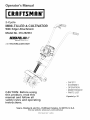
2-Cycle
MINI-TILLER
& CULTIVATOR
With Edger Attachment
Model
No. 316.292561
•
•
•
•
•
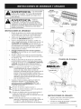
CAUTION:
Before using
this product, read this
manual and follow
all
.safety rules and operating
instructions.
Sears, Roebuck
SAFETY
ASSEMBLY
OPERATION
MAINTENANCE
PARTS LIST
Espa#o_
and Co., Hoffman
Visit our website:
Estates,
www.sears.com/craftsman
P/N 769-01527
(2/05)
IL 60179, U.S.A.
p. 19
TABLE OF CONTENTS
Warranty
Operating Instructions
.................................
Service Information
2
.........................
Rules for Safe Operation
2
.....................
3
Know Your Unit ............................
6
Assembly Instructions
7
......................
Maintenance and Repair Instructions ...........
12
Cleaning and Storage .......................
15
Troubleshooting
16
Specifications
Chart ......................
.............................
EPA Warranty Information
Oil and Fuel Information
Starting/Stopping
.......................
......................
Instructions
Full Two-Year
Warranty
17
...................
18
Parts List .............................
9
................
11
Repair Protection Agreement ....
10
Service Numbers ...................
on Craftsman
Mini-Tiller
35-36
Inside Back Cover
Back Cover
and Cultivator
For two (2) years from the date of purchase, if this Craftsman Equipment is maintained, lubricated, and tuned up
according to the instructions to the operator's manual, Sears will repair or replace free of charge any parts found to be
defective in material or workmanship. Warranty service is available free of charge by returning Craftsman equipment to
your nearest Sears Service Center. In-home warranty service is available but a trip charge will apply. This Warranty
applies only while this product is in the United States.
This Warranty
does not cover:
Expendable items which become worn during normal use, such as spark plugs, air cleaners, belts, and oil filters.
, Tire replacement or repair caused by punctures from outside objects, such as nails, thorns, stumps, or glass.
Repairs necessary because of operator abuse, including but not limited to, damage caused by objects, such as stones
or metal debris, oversized stock, impacting objects that bend the frame or crankshaft, or over-speeding the engine.
Repairs necessary because of operator negligence, including but not limited to, electrical and mechanical damage
caused by improper storage, failure to use the proper grade and amount of engine oil, or failure to maintain the
equipment according to the instructions contained in the operator's manual.
Engine (fuel system) cleaning or repairs caused by fuel determine to be contaminated
fuel should be used within 30 days of its purchase date.
Equipment used for commercial
or oxidized (stale). In general,
or rental purposes.
TO LOCATE THE NEAREST SEARS SERVICE CENTER OR TO SCHEDULE SERVICE, SIMPLY CONTACT SEARS AT
1-800-4-MY-HOME®.
This warranty gives you specific legal rights and you may also have other rights, which vary from state to state.
CALIFORNIA
PROPOSITION
65 WARNING
THE ENGINE EXHAUST FROM THIS
PRODUCT CONTAINS CHEMICALS
KNOWN TO THE STATE OF CALIFORNIA
TO CAUSE CANCER, BIRTH
OR OTHER REPRODUCTIVE
DEFECTS
HARM.
SPARK ARRESTOR
NOTE
NOTE: For users on U.S. Forest Land and in the
states of California, Maine, Oregon and Washington.
All U.S. Forest Land and the state of California (Public
Resources
Codes 4442 and 4443), Oregon
and
Washington
require,
by law that certain
internal
combustion engines operated on forest brush and/or
grass-covered areas be equipped with a spark arrestor,
maintained in effective working order, or the engine be
constructed, equipped and maintained for the prevention
of fire. Check with your state or local authorities for
regulations pertaining to these requirements. Failure to
follow these requirements could subject you to liability or
a fine. This unit is factory
equipped
with a spark
arrestor.
If it requires replacement,
ask your LOCAL
SERVICE DEALER to install the Accessory
Part
#753-04925 Spark Arrestor Kit.
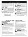
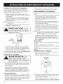
Thepurposeof safetysymbolsis toattractyour
attentionto possibledangers.Thesafetysymbols,
andtheirexplanations,
deserveyourcarefulattention
andunderstanding.
Thesafetywarningsdo notby
themselves
eliminateanydanger.Theinstructions
or
warningstheygivearenotsubstitutes
for proper
accidentprevention
measures.
SYMBOL
SYMBOL
result in serious injury to yourself or to
others. Always follow the safety precautions
to reduce the risk of fire, electric shock and
personal injury.
indicates
WARNING"
danger,
warning or caution. Attention is required in
order to avoid serious personal injury. May
be used in conjunction with other symbols
or pictographs.
CAUTION"
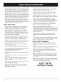
ALL
SAFETY INSTRUCTIONS
INSTRUCTIONS
BEFORE OPERATING
WARNING" []you
When usingtheunit,
must followthe
safetyrules,Pleasereadtheseinstructions
beforeoperatingtheunitinorderto ensure
thesafetyoftheoperatorand any bystanders.
Pleasekeep these instructions
forlater
use.
Read the instructions carefully. Be familiar with the
controls and proper use of the unit.
Do not operate this unit when tired, ill, or under the
influence of alcohol, drugs, or medication.
Children and teens under the age of 15 must not use
the unit, except for teens guided by an adult.
All guards and safety attachments must be installed
properly before operating the unit.
Inspect the unit before use. Replace damaged parts.
Check for fuel leaks. Make sure all fasteners are in
place and secure. Replace parts that are cracked,
chipped, or damaged in any way. Do not operate the
unit with loose or damaged parts.
Fa,uro
toobey
a
[] safety warning may
result in property damage or personal injury
to yourself or to others. Always follow the
safety precautions to reduce the risk of fire,
electric shock and personal injury.
Read the Operator's Manual(s) and follow all
warnings and safety instructions.
Failure to do so can result in serious injury to the
operator and/or bystanders.
READ
Failoroto
obey
a
[] safety warning can
result in injury to yourself and others.
Always follow the safety precautions to
reduce the risk of fire, electric shock and
personal injury.
NOTE: Advises you of information or instructions vital to
the operation or maintenance of the equipment.
• IMPORTANT
i
DANGER: safety
F0,uroto
obey
a
warning will
MEANING
SAFETY ALERT:
MEANING
•
Carefully inspect the area before starting the unit.
Remove all debris and hard or sharp objects such as
glass, wire, etc.
Be aware of the risk of injury to the head, hands and
feet.
Clear the area of children, bystanders, and pets. At a
minimum, keep all children, bystanders, and pets
outside a 50 feet (15 m.) radius; there still may be a
risk to bystanders from thrown objects. Bystanders
should be encouraged to wear eye protection. If you
are approached, stop the unit immediately.
Squeeze the throttle control and check that it returns
automatically to the idle position. Make all adjustments
or repairs before using unit.
SAFETY
WARNINGS
FOR GAS UNITS
WARNING:
Gasolineishighly
flammable,and its
vaporscan explode ifignited.
Take the
following
precautions:
Store fuel only in containers specifically designed and
approved for the storage of such materials.
Avoid creating a source of ignition for spilled fuel. Do
not start the engine until fuel vapors dissipate.
Alwaysstoptheengineandallowitto coolbeforefilling
thefueltank.Neverremovethecapofthefueltank,or
addfuel,whentheengineis hot.Neveroperatetheunit
withoutthefuelcapsecurely
inplace.Loosenthefuel
tankcapslowlyto relieveanypressureinthetank.
Mixandaddfuelina clean,well-ventilated
outdoorarea
wheretherearenosparksor flames.Slowlyremove
the
fuelcaponlyafterstoppingengine.Donotsmokewhile
fuelingormixingfuel.Wipeupanyspilledfuelfromthe
unitimmediately.
Alwayswipeunitdrybeforeusing.
Movetheunitatleast30feet(9.1m)fromthefueling
sourceandsitebeforestartingtheengine.Donot
smokeor allowsparksandopenflamesnearthearea
whileaddingfuelor operatingtheunit.
WHILE
OPERATING
Never start or run the unit inside a closed room or
building. Breathing exhaust fumes can kill. Operate
this unit only in a well ventilated outdoor area.
Wear safety glasses or goggles that are marked as
meeting ANSI Z87.1-1989 standards. Also wear
ear/hearing protection when operating this unit. Wear
a face or dust mask if the operation is dusty. Long
sleeve shirts are recommended.
Wear heavy, long pants, boots and gloves. Do not
wear loose clothing,jewelry, short pants, sandals or
go barefoot. Secure hair above shoulder level.
This unit has a clutch. The tines remains stationary
when the engine is idling. If it does not, have the unit
adjusted by an authorized service technician.
Be sure the tines are not in contact with anything
before starting the unit.
Use the unit only in daylight or good artificial light.
Avoid accidental starting. The operator and unit must
be in a stable position while starting. See
Starting/Stopping Instructions.
Use the right tool. Only use this tool for the purpose
intended.
Use extreme caution when reversing or pulling the unit
towards you.
Do not overreach. Always keep proper footing and
balance. Take extra care when working on steep
slopes or inclines.
Always hold the unit with both hands when operating.
Keep a firm grip on the grips.
Keep hands, face, and feet at a distance from all
moving parts. Do not touch or try to stop the tines
when they are rotating.
,
Do not touch the engine or muffler. These parts get
extremely hot from operation. They remain hot for a
short time after you turn off the unit.
"
Do not operate the engine faster than the speed
needed to cultivate. Do not run the engine at high
speed when you are not cultivating.
Always stop the engine when cultivating is delayed or
when walking from one cultivating location to another.
If you strike or become entangled with a foreign
object, stop the engine immediately and check for
damage. Do not operate before repairing damage. Do
not operate the unit with loose or damaged parts.
Stop and switch the engine to off for maintenance,
repair, or to install or remove the tines.
Use only original equipment manufacturer
replacement parts and accessories for this unit. These
are available from your authorized service dealer. Use
of any unauthorized parts or accessories could lead to
serious injury to the user, or damage to the unit, and
void your warranty.
Keep unit clean of vegetation and other materials.
They may become lodged between the tines and
guard.
To reduce fire hazard, replace faulty muffler and spark
arrestor, keep the engine and muffler free from grass,
leaves, excessive grease or carbon build up.
OTHER
SAFETY
WARNINGS
Never store the unit, with fuel in the tank, inside a
building where fumes may reach an open flame or
spark.
Allow the engine to cool before storing or transporting.
Be sure to secure the unit while transporting.
Store the unit in a dry area, locked up or up high
to prevent unauthorized use or damage, out of the
reach of children.
Never douse or squirt the unit with water or any other
liquid. Keep handles dry, clean and free from debris.
Clean after each use. See the Cleaning and Storage
instructions.
, Keep these instructions. Refer to them often and use
them to instruct other users. If you loan someone this
unit, also loan them these instructions.
SAVE THESE
INSTRUCTIONS
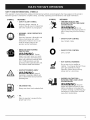
SAFETY
AND iNTERNATiONAL
SYMBOLS
This operator's manual describes safety and international symbols and pictographs that may appear on this product.
Read the operator's manual for complete safety, assembly, operating and maintenance and repair information.
SYMBOL
MEANING
SYMBOL
• THROWN OBJECTS AND
ROTATING CUTTER CAN CAUSE
SEVERE INJURY
• SAFETY ALERT SYMBOL
Indicates danger, warning, or
caution. May be used in conjunction
with other symbols or pictographs.
WARNING: Donot
operate without the proper guards in
place. Keep away from the rotating
tines.
WARNING - READ OPERATOR'S
MANUAL
Read the Operator's Manual(s) and
follow all warnings and safety
instructions. Failure to do so can
result in serious injury to the
operator and/or bystanders.
WEAR EYE AND HEARING
PROTECTION
WARNING: Thrown
objects and loud noise can cause
severe eye injury and hearing loss.
Wear eye protection meeting ANSI
Z87,1-1989 standards and ear
protection when operating this unit.
Use a full face shield when needed.
KEEP BYSTANDERS AWAY
MEANING
I
O
• ON/OFF STOP CONTROL
ON / START / RUN
ON/OFF STOP CONTROL
OFF or STOP
HOT SURFACE WARNING
Do not touch a hot muffler or
cylinder. You may get burned. These
parts get extremely hot from
operation. When turned off they
remain hot for a short time.
WARNING:
Keep all
bystanders, especially children and
pets, at least 50 feet (15 m.) from the
operating area.
WARNING:
• UNLEADED FUEL
Always use clean, fresh unleaded fuel.
• OiL
Refer to operator's
proper type of oil.
GARDEN CULTIVATORS =
ROTATING TINES CAN CAUSE
SEVERE INJURY
manual for the
Stopthe
engine and allow the tines to stop
before installing or removing tines,
or before cleaning or performing any
maintenance. Keep hands and feet
away from rotating tines.
Applications
Cultivating
sod and light to medium
Cultivating
in garden
areas, around
soil
trees, etc.
Edging
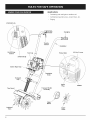
STOP/OFF (0)
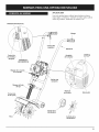
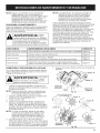
\
Handgrip
Throttle
Control
Handlebar
OnlOff Stop
Control
Primer Bulb
Fuel Cap
STARTION
EZ Fire
TM
Lever
\
(I)
Starter Rope Grip
Handlebar
Knob
Transport
Grip
Spark
Plug
Tine Guard
\
Transport Roller
Assembly
Edger
Wheel
Cultivator
Tines
Edger
Blade
Muffler
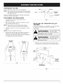
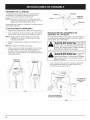
ASSEMBLING
THE UNiT
Hole
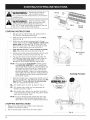
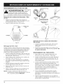
Before operating, position the unit's handlebars.
NOTE: You may also need to reposition the roller height
before using the cultivator. Refer to the Adjusting
Tine Depth section.
Bolt
Handlebar
Knob
Begin by carefully unpacking the contents and making
sure that nothing is damaged.
POSITIONING
THE HANDLEBARS
1.
Loosen the two knobs on the inside of the
handlebars (Fig. 1).
2.
With the unit upright, swing the handlebars up into
the operating position (Fig. 1).
NOTE: Take care not to pinch the throttle cable or
switch wires when positioning the handlebar.
3.
Tighten the knobs to secure the handlebars in place
(Fig. 2).
NOTE: Do not over-tighten
.
.........
_
Handlebars
\.
Fig. 2
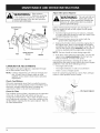
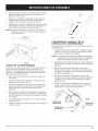
INSTALLING
ASSEMBLY
THE
TRANSPORT
ROLLER
If the roller assembly is not installed, or if you ever need
to remove or reinstall it, perform the following
instructions:
WARNING:
the knobs.
To avoid
injury
the
tines,
wear from
heavy glovesand a longsleeveshirtwhen
installing the roller assembly.
Readjust the throttle cable and switch the wires so
they are smooth and tight against the handlebar
assembly. This will help prevent them from catching
or snagging during normal operation.
personal injury, the
WARNING:
Toprevent serious
roller assembly must be installed when
operating
Handlebar
Knobs
Handlebar
Knobs
the unit.
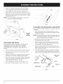
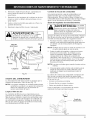
1. With the unit on its side, place the transport roller
assembly on the underside of the tine guard (Fig. 3).
Guard
"" Transport
Roller
Assembly
Fig. 1
Wing Nuts &
Lock Washers
Fig. 3
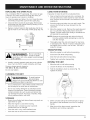
2.
Install a carriage bolt through each of the slotted
holes in the roller bracket and into the tine guard.
3.
On the TOP side of the tine guard, install a lock
washer and a wing nut onto each of the bolts (Fig. 3).
4.
Make sure the square shoulder of the bolts is pushed
through the slotted holes in the roller bracket. Tighten
the wing nuts (Fig. 4).
Up
NOTE: Do not over-tighten the wing nuts. Loosen the
wing nuts to adjust roller height.
/
Down
f
\\\\
Fig. 5
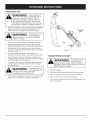
ATTACHING
THE EDGER WHEEL AND BLADE
To convert the mini-tiller cultivator to an edger, proceed
as follows:
1.
Transport
Roller
Assembly
Fig. 4
ADJUSTING
TINE DEPTH
Tine adjustment will vary depending on the type of soil
being cultivated and how it will be used. Generally,
adjusting the tines to break the soil 4 to 6 inches is
recommended for most gardens. Adjust the tines as
follows:
,
Stop the engine and disconnect the spark plug wire.
2.
Loosen (do not remove) the two wing nuts on the
tine guard (Fig. 5).
3.
Slide the roller bracket assembly down for shallower
penetration, and up for deeper tine penetration.
4.
,
6.
Push the On/Off switch to Off (O) position to stop
engine and tines and disconnect spark plug to avoid
accidental starting.
NOTE: It may be necessary to lay the mini-tiller back in a
horizontal position on a flat level surface with the
upper handle touching the ground.
2.
,
,
,
Remove the click pin from each end of the tine shaft
and slide the tines off the shaft.
Slide the edger wheel, with the hub facing inward,
onto the right side of the tine shaft and secure with
the click pin in the inside hole (Fig. 6).
Slide the edger blade with the hub facing out onto
the left side of tine shaft and secure with the click pin
in the inside hole (Fig. 6).
Guide the edger blade along a flowerbed, sidewalk,
or driveway with the edger wheel along the outside
edge. Use the edger guide line to line up edger blade.
Edger Guide
Line
Once the tines are in the desired position, tighten the
wing nuts, making sure that the carriage bolts are
seated properly through the bracket.
Hub
If the tine depth is incorrect, repeat steps 2 to 4.
Reconnect the spark plug wire and continue use.
Edger Wheel
Click Pin
Edger Blade
Fig. 6
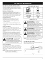
OiL AND
FUEL
MiXiNG
iNSTRUCTiONS
FUEL MIXTURE
Old and/or improperly mixed fuel are the main reasons
for the unit not running properly. Be sure to use fresh,
clean unleaded fuel. Follow the instructions carefully for
the proper fuel/oil mixture.
Definition
of Blended
i ,
Fuels
Today's fuels are often a blend of gasoline and
oxygenates such as ethanol, methanol, or MTBE (ether).
Alcohol-blended fuel absorbs water. As little as 1%
water in the fuel can make fuel and oil separate. It forms
acids when stored. When using alcohol-blended fuel,
use fresh fuel (less than 60 days old).
UNLEADED GAS
2 CYCLE OIL
1 GALLON US
(3.8 LITERS)
3.2 FL. OZ.
1 LITER
25 ml
Using Blended
Fuels
If you choose to use a blended fuel, or its use is
unavoidable, follow recommended precautions:
WARNING:
, Always agitate the fuel mix before fueling the unit
Gaso,oe
extremely
flammable. IgnitedVapors may explode.
Always stop the engine and allow itto cool
beforefilling
the fueltank.Do not smoke
whilefilling
the tank.Keep sparks and open
flames at a distancefrom the area.
, Drain the tank and run the engine dry before storing
the unit
Fuel Additives
The bottle of 2-cycle oil that came with your unit
contains a fuel additive which will help inhibit corrosion
and minimize the formation of gum deposits. It is
recommended that you use Craftsman 2-cycle oil with
this unit.
WARNING:
Remove fuel cap
slowly to avoid injury
from fuel spray. Never operate the unit
without the fuel cap securely in place.
If Craftsman 2-cycle oil is unavailable, use a good 2cycle oil designed for air-cooled engines along with a
fuel additive, such as STA-BIL :' Gas Stabilizer or an
equivalent. Add 0.8 oz. (23 ml.) of fuel additive per gallon
of fuel according to the instructions on the container.
NEVER add fuel additives directly to the unit's fuel tank.
Correct
(95 ml)
MIXING RATIO - 40:1
, Always use the fresh fuel mix explained in your
operator's manual
Using
TABLE
WARNING:
Add fuel in a clean,
well ventilated
outdoor area. Wipe up any spilled fuel
immediately. Avoid creating a source of
ignition for spilt fuel. Do not start the engine
until fuel vapors dissipate.
CAUTION" [] operation
Forproper
engine
and
NOTE: Dispose of the old fuel/oil mix in accordance to
Federal, State and Local regulations.
maximum reliability, pay strict attention to
the oil and fuel mixinginstructions
on the
2-cycle oil container.Using
improperly mixed
fuel can severely damage the engine.
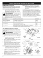
FiLLiNG
THE FUEL TANK
Make sure the cultivator is in a horizontal position when
filling or adding fuel to the tank.
Fuel Mixture
Thoroughly mix the proper ratio of 2-cycle engine oil
with unleaded gasoline in a separate fuel can. Use a 40:1
fuel/oil ratio. Do not mix them directly in the engine fuel
tank. See the Fuel Mixture Table for specific gas and oil
mixing ratios.
NOTE: One gallon (3.8 liters) of unleaded gasoline mixed
with one 3.2 oz. (95 ml.) bottle of
2-cycle oil makes a 40:1 fuel/oil ratio.
Fig. 7
IAIAE)I!I_||
l_,|tl__.
Operate this unit only in a
[] well- ventilated outdoor
area. Carbon monoxide exhaust fumes can be lethal in
a confined area.
WARNING"
Avoid accidental
OFF (0)
starting.
[] Make sure you are in the
starting position when pulling the starter rope
(Fig. 10). To avoid serious injury, the operator and unit
must be in a stable position while starting.
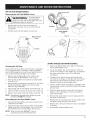
STARTING
Throttle
Control
INSTRUCTIONS
,
Mix gas with oil. Fill fuel tank with fuel/oil mixture.
See Oil and Fuel Mixing Instructions.
,
Make sure the On/Off Stop Control is in the ON [I]
position (Fig. 8).
Fully press and release the primer bulb 10 times,
slowly. Some amount of fuel should be visible in the
primer bulb and fuel lines (Fig. 9). If you can't see
fuel in the bulb, press and release the bulb as many
times as it takes before you can see fuel in it.
Primer
Bulb __!
Push the blue EZ Fire TM Lever towards the primer
bulb until it clicks and locks into place (Fig. 9).
Blue EZ Fire
Lever
Lay the unit on the ground horizontally, with the ends
of the handles resting on the ground (Fig. 10).
iiii ii
6.
Put your free hand on the fuel tank to stabilize the
unit. With your other hand, pull the starter rope out
with a smooth and steady pull until the engine
attempts to start. Repeat until the engine starts.
NOTE: The unit uses the Incredi-Pull TM starting system
with MAX FIRE IGNITION TM, which significantly
reduces the effort required to start the engine. You
must pull the starter rope out far enough to hear
the engine attempt to start. There is no need to
pull the rope briskly-- there is no harsh resistance
when pulling. Be aware that this starting method is
vastly different from (and much easier than) what
you may be used to.
Fig. 9
Starting
When the engine starts, squeeze the throttle control
for 15 to 30 seconds. This will warm up the unit. The
blue EZ Fire TM Lever will click off automatically
when you squeeze the throttle control.
..........................
IF... The engine does not start, go back to step 3.
IF,,, The engine stops while you are squeezing the
throttle, go back to step 4.
IF,,, The engine stops before you squeeze the throttle
control, hold the throttle control and pull the starter
rope until the trimmer starts.
NOTE: If you are having trouble starting the unit or are
operating in extreme temperatures (below 40° F,
above 90° F), refer to the Troubleshooting section.
STOPPING
INSTRUCTIONS
1.
Release your hand from the throttle control. Allow the
engine to cool down by idling.
2.
Put the On/Off Stop Control in the OFF (O) position.
Fig. 10
10
TM
Position
OPERATING
TiPS
WARNING" []
Dress properly to
reduce the risk of
injury when operating this unit. Do not
wear loose clothing orjewelry. Wear eye
and ear/hearing protection. Wear heavy
long pants, boots and gloves. Do not wear
short pants, sandals or operate barefoot.
Move the cultivator to the work area prior to starting the
engine. Transport the cultivator by pushing it on its
roller wheel or by carrying it by the transport grip.
Transport
Grip
WARNING" [] To
preveot
serious
personal injury,
never pick-up or carry the unit while the
engine is running.
2.
Start the unit by following the Starting Instructions.
3.
With the engine running and the tines off the ground,
depress the throttle control to increase the engine speed.
4.
Holding both of the handlebar grips firmly, slowly
lower the cultivator until the tines make contact with
the ground (Fig. 11).
5.
As cultivating action begins, pull back on the
cultivator so that the tines can penetrate the ground.
6.
Once the ground has been broken, continue at a
moderate pace until you are familiar with the controls
and the handling of the cultivator.
7.
To improve the depth of cultivation, pull back on the
unit as it moves forward to drive the tines deeper
into the ground.
WARNING" [] To
preveot
serious
personal injury, use
extreme caution when reversing
or pulling the unit towards you.
Fig. 11
TRANSPORTING
THE UNIT
WARNING: To
prevent
serious
personal injury,
always stop the engine when operation is
delayed or when transporting the unit from
one location to another
1.
Stop the engine.
2.
Slide the roller bracket assembly all the way down.
3. Tilt the unit back until the tines clear the ground.
8.
If the tines are digging too deep or not deep enough,
adjust them according to Adjusting -FineDepth.
4.
Push or pull the unit to the next location.
5.
If you need to move the unit over long distances, use
the transport grip.
11
MAINTENANCE
SCHEDULE
Perform these required maintenance procedures at the
frequency stated in the table. These procedures should
also be a part of any seasonal tune-up.
NOTE: Some maintenance procedures may require
special tools or skills. If you are unsure about
these procedures, take your unit to a Sears or
other qualified service dealer. Call 1-800-4-MYHOME® for more information.
IA#aDR||R|I__.
TO prevent serious
u u F-ill '_| _I | | u 1_jl [] injury,
neverperform
maintenanceor repairs
withunitrunning.
Always serviceand repaira coolunit.
Disconnectthesparkplugwireto ensurethat
the unitcannotstart.
NOTE: Maintenance, replacement, or repair of the
emission control devices and system may be
performed by a Sears or other qualified service
dealer. Call 1-800-4-MY-HOME®
for more
information.
In order to assure peak performance of your engine,
inspection of the engine exhaust port may be necessary
after 50 hours of operation. If you notice lost RPM, poor
performance or general lack of acceleration, this service
may be required. If you feel your engine is in need of this
inspection, refer service to a Sears or other qualified
service dealer. Call 1-800-4-MY-HOME®
for more
information. DO NOT attempt to perform this process
yourself as engine damage may result from contaminants
involved in the cleaning process for the port.
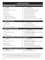
FREQUENCY
MAINTENANCE
Before starting engine
Fill fuel tank with fresh fuel mix
Page 9
Every 10 hours
Clean and re-oil air filter
Page 13
Check and clean spark arrestor
Page 14
Check spark plug condition and gap
Page 15
Inspect exhaust port and spark arrestor screen for clogging or
obstruction to assure maximum performance levels
Page 14
Every 25 hours
Every 50 hours
TINE REMOVAL
REQUIRED
REFER TO
AND REPLACEMENT
All 4 tines should be replaced at the same time because
they will wear evenly through normal use. Work on one
side at a time.
__A_r"
Tine
[] injury, always wear
WARNING"
To prevent serious
heavy gloves when handling the tines.
1.
Put the On/OFFStop Control in the STOP (O) position
and disconnect the spark plug boot from the plug.
NOTE: It may be necessary to lay the cultivator back in a
horizontal position on a flat level surface with the
handles touching the ground.
2.
3.
4.
Remove the click pin from each end of the tine shaft.
Slide the tines off of the shaft (Fig. 12a).
Clean and oil the shaft.
Cultivator
Front
Click
Pin
Hubs
Fig. 12a
Hubs on back side
When you are reinstalling tines, la_ out the tines and
compare them to those shown in Figure 12b. Note
specifics about each tine: its hub, curvature and
lettering ("A" or "B"). This will help make sure that
you are placing the correct tines in the correct order.
NOTE: If you look closely, you can see a slight curvature
in the tine tips. These curves should point toward
the front of the cultivator when the tines are
installed. Figure 12b shows the curve in each tine.
5.
Tine
"A" Tine
"B" Tine
"B" Tine
Hubs
Using Figures 12a and 12b for reference, slide on the
new tines with the hubs facing outward.
The tines are stamped "A" or "B." The tine order
should be "B, A, B, A" from left to right when facing
the cultivator from the front.
6.
12
Secure the new tines to the shaft with click pins. It
may be necessary to wash the dirt off the tines and
shaft to help during this entire process.
Cultivator
Front
"A" Tine
Fig. 12b
AIR FILTER MAINTENANCE
Removing
the Air Filter/Muffler
WARNING"
Cover
Toavoid
se ioos
[] personal injury,
always turn the unit off and allow it to cool
before you clean or service it.
6
1. Remove the four (4) screws securing the air
filter/muffler cover (Fig. 13). Use a # T20 Torx bit
screwdriver.
2.
Air Filter
Pull the cover from the engine. Do not force.
Blue EZ Fire
Lever
Screws
I
Inside Muffler
Cover
Fig. 14
TM
Screws
!
Fig. 15
Fig. 13
SPARK
Cleaning
1.
the Air Filter
Clean and re-oil the air filter every 10 hours of operation.
It is an important item to maintain. Failure to maintain
your air filter properly can result in poor performance or
can cause permanent damage to your engine.
,
,
3.
,
5.
Remove the air filter/muffler cover. Refer to the
Removing the Air filter/Muffler Cover section.
Remove the air filter from inside the air filter/muffler
cover (Fig. 14).
Wash the filter in detergent and water (Fig. 14). Rinse
the filter thoroughly. Squeeze out excess water.
Allow it to dry completely.
,
Reinstalling
the Air filter/Muffler
Cover
1.
Place the air filter/muffler cover over the back of the
carburetor and muffler.
2.
Insert the four (4) screws into the holes in the air filter/
muffler cover (Fig. 13) and tighten. Use a # T20 Torx
bit screwdriver. Do not over tighten. Do not force.
Remove air filter/muffler cover. Refer to Removing
the Air Filter/Muffler Cover.
Locate the muffler, but do not remove it. Find the
screw on the bottom of the muffler (Fig. 16). Remove
the screw using either a torx #20 or flat blade
screwdriver.
Carefully
Two tabs
Flip open
then pull
,
Using a small flat blade screwdriver, carefully pry the
spark arrestor screen out from the inside of the spark
arrestor hood.
,
6.
Replace the air filter inside the muffler cover (Fig. 14).
NOTE: Operating the unit without the air filter and cover
assembly will VOID the warranty.
MAINTENANCE
,
Apply enough SAE 30 oil to lightly coat the filter (Fig. 15).
Squeeze the filter to spread and remove extra oil (Fig. 15).
ARRESTOR
pry up the left side spark arrestor hood.
act as hinges on the right side of the hood.
the spark arrestor hood like a door and
its tabs out of the muffler slots.
Clean the spark arrestor screen with a wire brush.
Replace it if it is damaged, or if you are unable to
clean it thoroughly.
Reinstall the spark arrestor screen snugly back into
the spark arrestor hood.
7. Reinstall the two hood tabs into the two muffler slots
and flip the spark arrestor hood closed.
8. Replace the screw you removed in Step 2 and tighten
it securely.
9. Reinstall the air filter/muffler cover.
,
NOTE: Make sure the blue EZ-Fire TM Lever is
positioned away from the primer bulb.
13
WARNING:
If
the
exhaust
deflector
assembly
Adjust
Engine
Slots
/
clothing and
to prevent
If after checking the fuel mixture and cleaning the air
filter the engine still will not idle, adjust the idle speed
screw as follows:
1.
Start the engine and let it run for about 2-3 minutes
at a high speed (full throttle) to warm up. Refer to the
Starting/Stopping Instructions.
NOTE: Ensure the tines are not in contact with the
ground when adjusting the idle.
Screw
Spark Arrestor
Screen
Tabs
Release the throttle control and let the engine idle. If
the engine stops, insert a small phillips or flat blade
screwdriver into the hole in the muffler cover (Fig. 17).
Turn the idle speed screw clockwise 1/8 of a turn at
a time (as needed) until the engine idles smoothly.
NOTE: The tines should not rotate during engine idle.
Muffler
Fig. 16
ADJUSTMENTS
The engine's idle speed adjuster is adjustable through
the air filter/muffler cover (Fig 17).
NOTE: Careless adjustments can seriously damage your
unit. A Sears Parts & Repair center or other
qualified service dealer should make carburetor
adjustments.
Check
The
unit
willstillrun
during idle speed
adjustments. Wear protective
observe all safety instructions
serious personal injury.
2.
CARBURETOR
Adjuster
WARNING:
isnot tightenedsecurely,itcould fall
off
causing damage to the unitand possible
serious personal injury.
Spark Arrestor
Hood
Idle Speed
3.
If the tines rotate when the engine idles, turn the idle
speed screw counterclockwise
1/8 of a turn at a
time (as needed), to reduce idle speed.
Checking the fuel mixture, cleaning the air filter, and
adjusting the idle speed screw should solve most engine
problems. If not and all the following are true:
The engine will not idle
The engine hesitates or stalls on acceleration
There is a loss of engine power
Have the carburetor adjusted by a Sears Parts & Repair
center or other qualified service dealer.
Fuel Mixture
Old and/or improperly mixed fuel is usually the reason
for the unit not running properly. Drain and refill the tank
with fresh, properly mixed fuel prior to making any
adjustments. Refer to Of and Fuel Information.
Clean
Air Filter
Idle Speed Adjuster
The condition of the air filter is important to the operation
of the unit. A dirty air filter will restrict air flow and
change the air/fuel mixture. This is often mistaken for an
out of adjustment carburetor. Check the condition of the
air filter before adjusting the idle speed adjuster. Refer to
Air Filter Maintenance.
Fig. 17
14
REPLACING
THE
SPARK
PLUG
LONG TERM STORAGE
Use a Champion RDJ7Y spark plug. The correct air gap
is 0.020 in. (0.5 mm). Remove the plug after every 25
hours of operation and check its condition.
1. Stop the engine and allow it to cool. Grasp the plug
wire firmly and pull the cap from the spark plug.
If you plan to store the unit for an extended time:
1. Drain all fuel from the fuel tank into a container. Do
not use fuel that has been stored for more than 60
days. Dispose of the old fuel in accordance to local
regulations.
2.
Clean dirt from around the spark plug. Remove the
spark plug from the cylinder head by turning a 5/8 in.
socket counterclockwise.
2.
3.
Replace cracked, fouled or dirty spark plug. Set the air
gap at 0.020 in. (0.5 mm) using a feeler gauge (Fig. 18).
.
Start the engine and allow it to run until it stalls. This
ensures that all fuel has been drained from the
carburetor.
Allow the engine to cool. Remove the spark plug and
put 1 oz. (30 ml) of high quality motor oil into the
cylinder. Pull the starter rope slowly to distribute the
oil. Reinstall the spark plug.
NOTE: Remove the spark plug and drain all of the oil
from the cylinder before attempting to start the
unit after storage.
0.020 in.
(0.5 ram.)
.
Fig. 18
Thoroughly clean the unit and inspect for any loose
or damaged parts. Repair or replace damaged parts
and tighten loose screws, nuts or bolts. The unit is
ready for storage.
TRANSPORTING
Allow the engine to cool before transporting.
WADR|IIR|q'_,.
Do notsand blast,
I
•--_m_.mi, mi _,,_, scrape or clean
electrodes. Grit in the engine could damage
the cy nder.
J
4.
Install a correctly-gapped spark plug in the cylinder
head. Turn the 5/8 in. socket clockwise until snug.
If using a torque wrench torque to:
110-120 in.. lb. (12.3-13.5 N. m)
Do not over tighten.
CLEANING
Secure the unit while transporting.
Drain the fuel tank before transporting.
Tighten fuel cap before transporting.
MOVING
THE UNIT
1. Allow the unit to cool before moving.
2.
Loosen the knobs on the handlebar.
3.
Fold the handlebars down as shown (Fig. 19).
Tighten the knobs.
THE UNIT
Handlebar
Knobs
WARNING" [] To
avoid
serious
personal injury,
always turn your unit off and allow it to cool
before you clean or service it.
Use a small brush to clean off the outside of the unit
and to keep the air vents free of obstructions.
Do not use strong detergents or petroleum based
cleaners, like kerosene. Some household cleaners
contain aromatic oils such as pine and lemon that
can damage the plastic housings or handles. Wipe
off any moisture with a soft cloth.
/
Fig. 19
STORAGE
Never store a fueled unit where fumes may reach an
open flame or spark.
.
Allow the engine to cool before storing.
Store the unit in a locked up area to prevent
unauthorized use or damage.
.
Either carry the unit by the shaft tube grip or grasp
the center of the handlebar to use it as a carrying
handle.
After the unit has been moved, reposition the
handlebars and continue operation.
Store the unit in a dry, well-ventilated area.
Store the unit out of the reach of children.
15
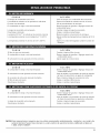
ACTION
CAUSE
Empty fuel tank
Fill fuel tank with new fuel
Primer bulb wasn't pressed enough
Press primer bulb fully and slowly 10 times
Engine is flooded
Squeeze the trigger and pull the starter rope
Old fuel
Drain gas tank and add fresh fuel
Fouled spark plug
Replace or clean the spark plug
Plugged spark arrestor
Clean or replace spark arrestor
EZ Fire lever wasn't flipped/set
Move lever to the starting position
The outside temperature
is below 40 ° F
Pull the starter rope up to 10-15 times
The outside temperature
is above 90 ° F
Squeeze the throttle control and pull the starter rope
CAUSE
ACTION
Air filter is plugged
Replace or clean the air filter
Old fuel
Drain gas tank and add fresh fuel
Improper carburetor adjustment
Adjust according to the Carburetor Adjustments section
CAUSE
Old fuel
ACTION
Drain gas tank and add fresh fuel
Improper carburetor adjustment
Take to a Sears Parts & Repair center or other qualified
service dealer for an adjustment
Dirty air filter
Clean or replace the air filter
Plugged spark arrestor
Clean or replace spark arrestor
CAUSE
ACTION
Old fuel
Drain gas tank and add fresh fuel
Improper carburetor adjustment
Take to a Sears Parts & Repair center or other qualified
service dealer for an adjustment
Fouled spark plug
Replace or clean the spark plug
Plugged spark arrestor
Cultivator tines bound with debris
Clean or replace spark arrestor
CAUSE
Spark plug gap is too small/close
Stop the unit, switch the On/OFFStop Control to
STOP, clean and remove any debris binding the tines
ACTION
Adjust gap to 0.020 inch (0.50 mm)
NOTE: For repairs beyond the minor adjustments
listed above, contact your nearest Sears Parts &
Repair center (1-800-4-MY-HOME
®) or other qualified service dealer for an adjustment.
16
Engine Type ...........................................................................................................................................
Air-Cooled, 2-Cycle
Displacement ...........................................................................................................................................................
31.5 cc
Idle Speed RPM .........................................................................................................................................
2,600-3,600 rpm
Operating RPM ...................................................................................................................................................
7,800+ rpm
Clutch Type .........................................................................................................................................................
Centrifugal
Ignition Type ..........................................................................................................................................................
Electronic
On/Off Stop Control .......................................................................................................................................
Rocker Switch
Spark Plug Type ......................................................................................................................................
Champion RDJ7Y
Spark Plug Gap ..................................................................................................................................
0.020 inch (0.50 mm)
Lubrication ...................................................................................................................................................
Fuel/Oil Mixture
Fuel/Oil Ratio ..................................................................................................................................................................
40:1
Carburetor .......................................................................................................................................
Diaphragm, All-Position
Starter ...........................................................................................................................
Incredi-Pull TM Starting Auto Rewind
Muffler .....................................................................................................................................................
Baffled with Guard
Throttle ............................................................................................................................................................
Fuel Tank Capacity .................................................................................................................................
Drive Shaft Tube ..................................................................................................................................................
Throttle Control ........................................................................................................................................
Cultivating Path Width (Maximum) .......................................................................................................
Cultivating Depth (Maximum) .................................................................................................................
Approximate Weight (no fuel) .........................................................................................................................
Spring Return
14 ounces (415 ml)
Steel Tube
Finger-Tip Trigger
9 inches (22.86 cm)
5 inches (12.7 cm)
26 lb. (12 kg)
_AII specifications are based on the latest product information available at the time of printing. We reserve the right to
make changes at any time without notice.
17
California
/ EPA Emission
Your Warranty
Control
Rights
Warranty
Statement
and Obligations
The California Air Resources Board, The Environmental Protection Agency and Sears are pleased to explain the emission
control system warranty on your 2005 and later small off-road engine. New small off-road engines must be designed, built
and equipped to meet stringent anti-smog standards. Sears, Roebuck and Co. must warrant the emission control system
on your small off-road engine for the periods of time listed below provided there has been no abuse, neglect or improper
maintenance of your small off-road engine.
Your Emission control system may include parts such as the carburetor or fuel-injection system, the ignition system, and
catalytic converter. Also included may be hoses, belts, connectors and other emission-related assemblies.
Where a warrantable condition exists, Sears will repair your small off-road engine at no cost to you including diagnosis,
parts and labor.
The 2005 and later small off-road engines are warranted
for two years.
engine is defective, the part will be repaired or replaced by Sears.
If any emission-related
part on your
Owner's Warranty
Responsibilities
. As the small off-road engine owner, you are responsible for the performance of the required maintenance listed in your
operator's manual. Sears recommends that you retain all receipts covering maintenance on your small off-road engine,
but Sears cannot deny warranty solely for the lack of receipts or for your failure to ensure the performance of all
scheduled maintenance.
. As the small off-road engine owner, you should however be aware that Sears may deny you warranty coverage if your
small off-road engine or a part has failed due to abuse, neglect, improper maintenance or unapproved modifications.
. You are responsible for presenting your small off-road engine to a Sears authorized service center as soon as problem
exists. The warranty repairs should be completed in a reasonable amount of time, not to exceed 30 days.
If you have any questions regarding your warranty rights and responsibilities,
you should call 1-800-4-MY-HOME
®.
Manufacturer's
Warranty
Coverage
. The warranty period begins on the date the engine or equipment is delivered to the retail purchaser.
. The manufacturer warrants to the initial owner and each subsequent purchaser, that the engine is free from defects in
material and workmanship which cause the failure of a warranted part for a period of two years.
. Repair and replacement of warranted part will be performed at no charge to the owner at an authorized Sears service
center. For the nearest location please contact Sears at: 1-800-4-MY-HOME ®.
. Any warranted part which is not scheduled for replacement, as required maintenance or which is scheduled only for
regular inspection to the effect of "Repair or Replace as Necessary" is warranted for the period. Any warranted part
which is scheduled for replacement as required maintenance will be warranted for the period of time up to the first
scheduled replacement point for that part.
. The owner will not be charged for diagnostic labor which leads to the determination
the diagnostic work is performed at an authorized Sears Service Center.
. The manufacturer
under warranty.
is liable for damages to other engine components
that a warranted part is defective if
caused by the failure of a warranted part still
. Failures caused by abuse, neglect or improper maintenance are not covered under warranty.
. The use of add-on or modified parts can be grounds for disallowing a warranty claim. The manufacturer is not liable to
cover failures of warranted parts caused by the use of add-on or modified parts.
. In order to file a claim, go to your nearest authorized Sears Service Center. Warranty service or repairs will be provided
at all authorized Sears Service Centers.
. Any manufacturer approved replacement part may be used in the performance of any warranty maintenance or repair
of emission related parts and will be provided without charge to the owner. Any replacement part that is equivalent in
performance or durability may be used in non-warranty
maintenance or repair and will not reduce the warranty
obligations of the manufacturer.
. The following components are included in the emission related warranty: engine, air filter, carburetor, primer, fuel lines,
fuel pick up/fuel filter, ignition module, spark plug and muffler.
18
INDICE
DE CONTENIDOS
Instrucciones de operacion
Garantia .................................
Llamadas a apoyo al cliente
19
.................
Normas para una operacion segura
Conozca su unidad ........................
Instrucciones
de ensamble
..................
Informacion del aceite y del combustible
Instrucciones
19
...........
24
.......
de arranque y apagado ..........
Garantia
20
23
26
27
..................
Instrucciones de mantenimiento y reparacion
Limpieza y almacenamiento
.................
Cuadro de solucion de problemas
28
...
............
29
32
33
Especificaciones ...........................
Lista de Piezas ...........................
34
35
EPA Garantia .............................
37
Cobertura de Gastos de Reparaciones .........
39
Numeros de Servicio .............
Contraportada
de la cultivadora/bordeadora
Craftsman
de dos a_os
Por un periodo de dos (2) ahos a partir de la fecha de compra, con la condicion de que a este equipo Craftsman se le
realiza el mantenimiento, la lubricacion y ajustes de acuerdo con las instrucciones que aparecen en el manual del
operador', Sears Ilevara a cabo reparaciones o reemplazos necesarios sin cargo cualquiera de las piezas que resulten
defectuosas en sus materiales o fabricacion. El servicio de garantia esta disponible sin cargo si Ileva su equipo Craftsman
al Centro de Servicio Tecnico de Sears mas cercano.EI servicio de garantia a domicilio esta disponible pero se aplicara un
cargo de traslado. Esta garantia es valida 0nicamente mientras el producto se encuentre dentro de los Estados Unidos.
Esta garantia no cubre:
, Articulos de duracion limitada que sufren desgaste bajo condiciones
encendido, purificadores de aire, correas y filtros de aceite.
normales de usol, tales como bujias de
Reemplazo o reparacion de neumaticos debido a pinchaduras causadas por objetos externos, tales como clavos,
espinas, tocones o vidrio.
Reparaciones necesarias debido al abuso del operador, incluyendo pero sin limitarse a daho causado por objetos,
tales como piedras o desechos de metal, troncos de un tamaho demasiado grande, objetos que hacen impacto que
puedan doblar la estructura o el carter o puedan sobreacelerar el motor.
Reparaciones necesarias debido a negligencia del operador, incluyendo pero sin limitarse a dahos electricos y
mecanicos causados por almacenamiento incorrecto, falla en la calidad o cantidad del aceite de motor utilizado, o
falla para mantener el equipo de acuerdo con las instrucciones contenidas en el manual del operador'.
Limpieza o reparaciones del (sistema de combustible del) motor causadas por combustible que se encontro que
estaba contaminado u oxidado (vencido). En general, el combustible deberia ser utilizadodentro de los 30 dias
posteriores a la fecha de compra.
Equipos utilizados para fines comerciales o de alquiler.
PARA UBICAR EL CENTRO DE SERVICIO TECNICO SEARS MAS CERCANO O PARA PROGRAMAR EL SERVlCIO
TECNICO, SIMPLEMENTE COMUNiQUESE CON SEARS AL TELEFONO 1-800-4-MY-HOME®.
Esta garantia le otorga derechos legales especificos y tambien
un estado a otto.
usted puede tener otros derechos, los cuales varian de
PARACHISPAS
PROPOSICION
65 DE CALIFORNIA
LAS EMISIONES DEL MOTOR DE ESTE
PRODUCTO CONTIENEN SUBSTANCIAS
QUIMICAS QUE EL ESTADO DE
CALIFORNIA CONOCE COMO CAUSANTES
DECANCER, DEFECTOS DE NACIMIENTO
U OTROS DAK!OS REPRODUCTIVOS.
NOTA: Para los usuarios en tierras forestales de los
EE.UU. y en los estados de California, Maine, Oregon
V Washmqton.
Todos los terrenos forestales de los
EE.UU. y e'] estado de California (Codigos de Recursos
Publicos 4442 y 4443), Oregon y Washington,. requieren
pot decreto, que c_ertos motores de combustion mterna
que se hagan funcionar en zonas boscosas y/o zonas
cubiertas
por pastizales,
esten equipados
con un
parachispas, que sean mantenidos en buen estado de
tuncionamiento
o que el motor sea construido,
este
equipado
y sea mantenido
para evitar incendios.
Consulte los reglamentos pertinentes a esos requisitos
con las autoridades estatales o locales. El incumplimiento
de esos requisitos puede resl:2onsabilizarle o someterle a
la imposici6n de una multa. Esta unidad rue equipada
en la f,ibrica
con un _p.arachis#as.
Si requiere
sustitucion, ha2 una Pantalla Paracl_ispas d isponible,
Pieza #753-04925 al contactar el departamento de servicio.
19
Los simbolos de seguridad se utilizan para Ilamar su
atencion sobre posibles peligros. Los simbolos de
seguridad y sus explicaciones merecen toda su atencion
y comprension. Los simbolos de seguridad no eliminan
ningun peligro por si mismos. Las instrucciones o
advertencias que ofrecen no substituyen las medidas
adecuadas de prevencion de accidentes.
SIMBOLO
SIMBOLO
PELIGRO:
ALERTA DE SEGURIDAD:
ADVERTENClA:
BIOTA: Le ofrece informacion o instrucciones que son
esenciales para la operacion o mantenimiento
del equipo.
PRECAUCION:
INFORMACION
DE
, Lea todas las instrucciones con cuidado. Conozca
bien los controles y el uso correcto de la unidad.
, No opere esta unidad si esta cansado, enfermo, o bajo
los efectos del alcohol, drogas o medicamentos.
, Los nihos y los adolescentes menores de 15 ahos no
deben operar las unidades, excepto por los
adolescentes guiados por un adulto.
Inspeccione la unidad antes de utilizarla. Cambie las
partes dahadas. Verifique si existen perdidas de
combustible. Asegurese de que los sujetadores esten
bien colocados y asegurados. Cambie las partes que
esten quebradas, cascadas o dahadas de cualquier
forma. No opere esta unidad con piezas flojas ni
dahadas.
Tenga en cuenta el riesgo de lesiones en la cabeza, manos
y pies.
Aleje a todos los nihos, espectadores y animales
domesticos. Mantenga a todos los nihos,
espectadores y animales domesticos a un radio de
por Io menos 50 pies (15 m); ann asi, puede existir un
riesgo de objetos despedidos contra los
espectadores. Debe sugerir a los espectadores que
usen proteccion ocular. Si alguien se le acerca, pare la
unidad de inmediato.
2O
el no seguir
una
advertencia de seguridad puede conducir a
dano patrimonial o a que usted u otras
personas sufran lesiones personales. Siga
siempre las precauciones de seguridad
para reducir el riesgo de incendio, descarga
electrica y lesiones personales.
Lea el manual del operador y siga todas las
advertencias e instrucciones de seguridad. De no
hacerlo, el operador y/o los espectadores
pueden
sufrir graves lesiones.
ANTEST
elno
seguir una
advertencia de seguridad puede conducir a
que usted u otras personas sufran lesiones.
Siga siempre las precauciones de seguridad
para reducir el riesgo de incendio, descarga
electrica y lesiones personales.
Indica peligro, advertencia o precaucion.
Debe prestar atencion para evitar sufrir
graves lesiones personales. Puede ser
utilizadojunto
con otros simbolos o figuras.
LEA TODAS LAS INSTRUCCIONES
LA OPERACION
noobe ecer
una
advertencia de
seguridad puede conducir a que usted u
otras personas sufran graves lesiones. Siga
siempre las precauciones de seguridad
para reducir el riesgo de incendio, descarga
electrica y lesiones personales.
SIGNIFICADO
• IMPORTANTE
SIGNIFICADO
DE SEGURIDAD,
, Oprima el control del regulador y verifique que regrese
automaticamente a la posicion de minima. Haga todos
los ajustes o reparaciones antes de usar la unidad.
ADVERTENCIAS
DE SEGURIDAD
UNIDADS A GASOLINA
PARA LAS
ADVERTENCIA:
La gasolina
es muy
inflamable y sus gases pueden explotar si se
encienden. Tome las siguientes precauciones:
, Guarde el combustible en envases que hayan sido
disehados y aprobados para el almacenamiento de
dichos materiales.
,
Antes de Ilenar el tanque de combustible, apague
siempre el motor y espere que se enfrie. No retire
nunca la tapa del tanque de combustible ni cargue
combustible mientras el motor este caliente. No opere
nunca la unidad sin la tapa del combustible colocada
firmemente en su lugar. Afloje la tapa del combustible
lentamente para disipar la presion del tanque.
Evite crear una fuente de encendido por combustible
derramado. No arranque el motor hasta que se hayan
disipado los vapores del combustible.
Mezcle y cargue el combustible en un area exterior
bien ventilada donde no haya chispas ni llamas. Quite
lentamente la tapa del combustible solo despues de
apagar el motor. No fume mientras carga o mezcla el
combustible. Limpie de inmediato todo el combustible
que se haya derramado.
Aleje la unidad a por Io menos 9,1 m (30 pies) del lugar
de carga de combustible antes de arrancar el motor.
No fume, mantenga las chispas y las llamas abiertas
lejos del area mientras carga el combustible u opera la
unidad.
DURANTE
LA OPERACiON
No arranque ni opere la unidad en una sala o edificio
cerrado. Los gases de escape de monoxido de
carbono pueden ser letales en un area cerrada. Opere
esta unidad solo en un area exterior bien ventilada.
Use lentes o galas de proteccion que cumplan con las
normas ANSI Z87.1, y proteccion para sus
oidos/audicion mientras opere esta unidad. Use
siempre una mascara
facial o para protegerse contra el polvo si la operacion
levanta polvo.
Use pantalones largos y gruesos, guantes y camisa de
manga larga. No use pantalones cortos, sandalias ni
trabaje descalzo.
Para reducir el riesgo de lesiones causadas por
objetos absorbidos por las partes giratorias, no use
ropa holgada, alhajas, pahuelos en el cuello, etc.
Recoja su cabello sobre el nivel de sus hombros.
Use la unidad unicamente con la luz del dia o con
buena luz artificial.
o Mantenga las superficies externas libres de aceite y
combustible.
Esta unidad cuenta con un embrague. Las puas no se
mueven mientras el motor esta en minima. Si se
mueven, haga que un tecnico de servicio autorizado
ajuste la unidad.
Verifique que las puas no hagan contacto con ningun
objeto antes de arrancar la unidad.
Evite arrancar la unidad accidentalmente. Coloquese
en posicion de inicio siempre que tire de la cuerda de
arranque. El operador y la unidad deben estar en una
posicion estable al comenzar. Lea las Instrucciones de
Arranque y Apagado.
Use la herramienta adecuada. No use esta unidad
para ninguna tarea para la cual no ha sido diseflada.
No fuerce la unidad. Realizara una mejor tarea y con
menor posibilidad de causar lesiones si se usa a la
velocidad para la que ha sido diseflada.
Tenga mucho cuidado cuando invierta o mueva la
unidad hacia usted.
No se extienda demasiado, tenga mucho cuidado
cuando trabaje en pendientes marcadas o inclinadas.
Mantenga siempre una posicion y equilibro
adecuados.
, Sostenga siempre la unidad con ambas manos
durante la operacion. Mantenga un buen agarre en los
mangos del manubrio.
o Mantenga las manos, la cara y los pies lejos de todas
las partes moviles. No toque ni intente detener las
puas mientras estan girando. No opere la unidad sin
las protecciones colocadas en su lugar.
°
No toque el motor, el silenciador ni la caja de
engranajes. Estas partes se calientan mucho durante
la operacion. Permanecen calientes durante un breve
periodo luego de apagar la unidad.
No opere el motor a una velocidad mayor que la
necesaria para realizar la tarea. No haga funcionar el
motor a alta velocidad cuando no Io use.
Pare siempre el motor cuando la operacion se demore
o cuando camine entre zonas de trabajo.
Apague.el motor para realizar el mantenimiento,
reparaclones, para instalar o sacar las puas. La unidad
debe estar apagada y las puas deben haberse
detenido para evitar lesiones.
Con el uso, las puas se afilan demasiado. Use siempre
guantes gruesos cuando maneje, retire, instale o
limpie las puas.
Use solo piezas y accesorios de repuesto del
fabricante del equipo original para esta unidad. Puede
obtenerlos en su proveedor de servicio autorizado. El
uso de piezas y accesorios que no son fabricante del
equipo original puede causar graves lesiones al
operador o el daho de su unidad, y la cancelacion de
su garantia.
Mantenga la unidad libre de vegetacion y otros
materiales. Pueden trabarse entre las pt]as y la caja de
engranajes o la proteccion.
Para reducir el riesgo de incendio, cambie los
silenciadores y amortiguadores de chispas defectuosos,
mantenga el motor y el silenciador libre de pasto, hojas,
grasa excesiva o acumulaciones de carbono.
Otras Advertencias
de Seguridad
, No guarde nunca la unidad con combustible en el
tanque en un edificio donde los gases puedan Ilegar a
una llama abierta o a una chispa.
o Espere que el motor se enfrie antes de guardar o
transportar la unidad. Asegurese de que la unidad este
segura al transportarla.
o Guarde la unidad bajo Ilave en un lugar adecuado y
seco para evitar que sea usada por personas no
autorizadas y se dahe, fuera del alcance de los nihos.
Nunca moje ni rode la unidad con agua ni con ningun
otro liquido. Mantenga las manUas secas, limpias y sin
residuos. Limpie la unidad luego de cada uso, lea las
instrucciones de Limpieza y Almacenamiento.
Guarde estas instrucciones. Consultelas con
frecuencia y utilicelas para ensehar a otros usuarios.
Si le presta esta unidad a alguien, prestele tambien
estas instrucciones.
CONSERVE ESTAS
INSTRUCCIONES
21
SIMBOLOS
DE SEGURIDAD
DE INTERCACIONALES
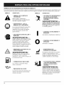
Este manual del operador describe los simbolos y figuras de seguridad e internacionalesque pueden aparecer en este producto. Lea el
manual del operador para obtener informacion completa acerca de la seguridad, ensamble, operacion y mantenimiento y reparacion.
SIMBOLO
SIGNIFICADO
SIMBOLO
SEGURIDAD
• LOS OBJETOS DESPEDIDOS
LA CUCHILLA
ROTATIVA
PUEDEN CAUSAR GRAVES
LESIONES
;_,I_
peligro, DE
advertencia
•llndica
SIMBOLO
ALERTA o DE
precaucion. Puede set utilizadojunto
con otros simbolos o figuras.
//"
_-_-_
_/
ADVERTENCIA:
• USE PROTECCION
AUDITIVA
OCULAR
Y
ADVERTENCIA: Los
objetos arrojados por la unidad y el ruido
fuerte pueden causar graves lesiones
oculares y perdida auditiva. Utilice
proteccion ocular que cumpla con las
normas ANSI Z87.1 y proteccion auditiva
cuando opere esta unidad. Use una
careta completa cuando la necesite.
• MANTENGA
ALEJADOS
ESPECTADORES
I
O
Use siempre combustible
nuevo y sin plomo.
limpio,
• CONTROL
APAGADO
DE ENCENDIDO
Y
ENCENDIDO/ARRANQUE/MARCHA
• CONTROL
APAGADO
DE ENCENDIDO
Y
APAGADO o PARADO
No toque un silenciador ni un cilindro
caliente. Puede quemarse. Estas
partes se calientan mucho con el uso.
Luego de apagarse permanecen
calientes durante un corto tiempo.
Mantenga a todos los espectadores,
en especial a nihos y animales
domesticos a por Io menos 50 pies (15
m.) del area de corte.
SIN PLOMO
No
• ADVERTENCIA
DE
SUPERFICIE
CALIENTE
A LOS
ADVERTENCIA:
• COMBUSTIBLE
Y
opere esta unidad si la proteccion
pl_istica de linea no esta colocada
en su lugar. Mantengase alejado de
los dientes giratorio.
• ADVERTENCIALEA EL
MANUAL
DEL OPERADOR
Lea el manual del operador y siga todas
las advertencias e instrucciones de
seguridad. De no hacerlo, el operador
y/o los espectadores pueden sufrir
graves lesiones.
SIGNIFICADO
|
CULTIVADORES PARA JARDINES
- LAS PUAS GIRATORIAS
PUEDEN CAUSAR GRAVES
LESIONES
ADVERTENCIA:
• INDICADOR
DE ACEITE
Consulte el manual dei operador para
obtener informacion acerca del tipo
correcto de aceite.
22
Apague el motor y espere que las
puas se detengan antes de instalar o
sacar las puas, o antes de realizar la
limpieza o todo tipo de mantenimiento.
Mantenga las manos y los pies lejos
de las puas giratorias.
APLICACION
Use esta unidad para cultivar tierra herbosa y tierra
negra ligera a mediana. Tambien se utiliza para cultivar
areas dejardines, alrededor de arboles, etc.
PARADO/APAGADO
(O)
\
Mango
Controldel
regulador
Manubrio
Control de
encendido y
Bombilla
del cebador
\
Palanca
EZ Fire
TM
ARRANQUE/
\
ENCENDIDO (I)
apagado
Mango de la cuerda
de arranque
-____.
Perilias de1
manubrio
Mango del tubo
del eje
Proteccion
de las plias
Bujia de
encendido
Silenciador
\
Rueda dela
Bordeadora
Puas
Cuchilla de la
Bordeadora
23
ENSAMBLE
DE LA UNIDAD
Arandela
Su cultivador parajardines ha sido completamente
ensamblado. El manubrio debera colocarse en la
posicion adecuada antes de la operacion.
NOTA: Antes de su operacion, es posible que deba
cambiar la posicion de la altura de la rueda. Lea
A_juste de la Profundidad de/as Puas.
Orificio
Perno
PeriBa del
manubrio
__:-T_:
Manubrio
Desembale con cuidado el contenido y verifique que no
haya piezas dahadas.
COLOCACION
DEL
MANUBRIO
Fig. 2
1. Afloje las dos perillas del lado interior del manubrio (Fig. 1).
2. Con la unidad en posicion vertical, gire el manubrio
hacia arriba hasta la posicion de operacion (Fig. 1).
INSTALACION
DEL ENSAMBLE
SOPORTE DE LA RUEDA
NOTA: Tenga cuidado de no pellizcar el cable del
regulador o los cables del interruptor cuando
coloque el manubrio.
Si el montaje de soporte de la rueda no esta instalado, o
si usted necesita siempre quitarlo o reinstalar, siga las
instrucciones que sobrevienen.
3. Ajuste las perillas para asegurar el manubrio en su
lugar.
NOTA: No ajuste las perillas demasiado.
4. Vuelva a ajustar el cable del regulador y los cables
del interruptor de modo que queden parejos y
estirados contra el ensamble del manubrio. Esto
evitara que se aprisionen o se desbarben durante la
operacion normal.
Perillas del
manubrio
Perillas dei
manubrio
DE
ADVERTENCIA:
Poro
ev tar
ADVERTENCIA:
Para
evitar
lesionarse
con las pL]as, use guantes gruesos y una
camisa de mangas largas cuando instale el
ensamble de soporte de la rueda.
graves
lesiones personales, el ensamble de soporte
de la rueda debera estar instalado cuando
opere la unidad.
1. Con la unidad sobre su lado, coloque el ensamble
de soporte de la rueda en el lado inferior de la
proteccion de las puas (Fig. 3).
Ensamble del
soporte de la
rueda
Fig.1
Tuerca de mariposa y
arandela de seguridad
Fig. 3
24
2.
Instale un perno de carro a traves de cada uno de los
orificios ranurados del soporte de la rueda y en la
proteccion de las pt]as.
3.
Instale una arandela de seguridad y una tuerca de
mariposa en cada uno de los pernos de la parte
superior de la proteccion de las puas (Fig. 3).
4.
Verifique que el hombro cuadrado de los pernos haya
atravesado los orificios ranurados del soporte de la
rueda. Ajuste las tuercas de mariposa (Fig. 4).
Arriba
NOTA: No a]uste demasiado las tuercas de mariposa.
Aflojar las tuercas de mariposa permite ajustar el
peso de la rueda.
Abajo
/
/
/
/
Fig. 5
CONEXION
CUCHILLA
DE LA RUEDA Y DE LA
DE LA BORDEADORA
Para convertir la cultivadora en una bordeadora,
siguientes pasos:
1.
siga los
Presione el interruptor encendido / apagado (O) para
detener el motor y los dientes y desconecte la bujia
para evitar un arranque accidental.
NOTA: Es posible que sea necesario ubicar la cultivadora/
bordeadora en posicion horizontal en una superficie
plana con la manija superior tocando el suelo
Fig.4
AJUSTE
Extraiga la chaveta del trinquete de cada extremo del
arbol del diente y deslice los dientes hasta extraerlos
del arbol.
3.
Deslice la rueda de la bordeadora, con el buje
mirando hacia adentro, en el lado derecho del arbol
del diente y asegurelo con la chaveta de trinquete en
el orificio interior (Fig. 6).
4.
Deslice la cuchilla de la bordeadora con el bu]e
mirando hacia el lado izquierdo del arbol del diente y
asegurelo con la chaveta de trinquete en el orificio
interior (Fig. 6).
5.
Deslice la cuchilla de la bordeadora a Io largo del
cantero, ]ardin, vereda o entrada con la rueda de la
bordeadora a Io largo del borde exterior.
DE LA PROFUNDIDAD
El ajuste de las puas podra variar de acuerdo al tipo de
tierra que cultiva y el modo en que sera usado. En
general, se recomienda a]ustar las puas para abrir la
tierra de 4 a 6 pulgadas para la mayoria de Iosjardines.
Ajuste las puas de este modo:
1. Pare el motor y desconecte el cable de la bujia de
encendido.
2.
Afloje (no retire) las dos tuercas de mariposa de la
proteccion de las puas (Fig. 5).
3.
Deslice el ensamble del soporte de la rueda hacia
aba]o para Iograr una penetracion mas superficial, y
hacia arriba para Iograr una penetracion mas
profunda.
4.
Una vez que las puas se encuentran en la posicion
deseada, ajuste las tuercas de mariposa, verificando
que los pernos de carro estan bien sentados a traves
del soporte.
5.
Si la profundidad
los pasos 2 a 4.
6.
2.
de las puas no es correcta, repita
Vuelva a conectar el cable de la bujia de encendido y
continue su uso.
Ru
e_d
Buje
a de la
Bordeadora
/
Cuchiiia de la
Bordeadora
Chaveta de
Trinqueta
_,,,_t
_J
Fig. 6
25
INSTRUCCIONES
PARA MEZCLAR
ACEITE Y EL COMBUSTIBLE
EL
El combustible viejo o mal mezclado son los motivos
principales del mal funcionamiento de la unidad.
Asegurese de usar combustible nuevo, limpio y sin
plomo. Siga las instrucciones en detalle para mezclar
correctamente el aceite y el combustible.
Definicion
de los combustibles
de mezcla
Los combustibles actuales con frecuencia son una mezcla
de gasolina y oxigenantes como por ejemplo etanol,
metanol o MTBE (eter). El combustible mezclado con
alcohol absorbe agua. Una cantidad tan pequeha como el
1% de agua en el combustible puede causar la separacion
del combustible y el aceite. Forma acidos cuando esta
almacenado. Cuando use combustible mezclado con
alcohol, use combustible nuevo (de menos de 60 dlas).
Uso de combustibles
GASOUNA
1 LITRO
25 mL
PROPORCION
seg[_n
antes de
en el combustible
La
ADVERTENCIA:
Saque
tapa del
ADVERTENCIA:
Si es inevitable, use un buen aceite de 2 ciclos
elaborado para motores enfriados por airejunto con un
aditivo para el combustible como por ejemplo el
estabilizador de gasolina STA-BIL o similar. Agregue
23 mL (0,8 onzas) de aditivo de combustible por galon
de combustible de acuerdo con las instrucciones del
envase. NUNCA agregue aditivos directamente en el
tanque de combustible de la unidad.
Para que el
" motor
funcione correctamente y con la mayor
fiabilidad, preste mucha atencion a las
Jnstrucciones de mezcla de aceJte y
combustible del envase de aceite de 2 ciclos.
El uso de combustible mezclado en forma
Jncorrecta puede daflar serJamente el motor.
ADVERTENCIA:
combustible lentamente para evitar lesionarse
con el rociado del combustible. No @ere
nunca la unidad sin la tapa del combustible
firmemente colocada en su hgar,
La botella de aceite de 2 ciclos que vino con su unidad
contiene un aditivo en el combustible que ayudara a
inhibir la corrosion y a reducir la formacion de depositos
de goma. Se recomienda que use solo el aceite de 2
ciclos con esta unidad.
PRECAUCION"
DE LA MEZCLA = 40 : 1
gasolina es
muy inflamable. Los gases pueden explotar
si se encienden. Apague siempre el motor y
espere que se enfrie antes de cargar el
tanque de combustible. No fume mientras
!lena el tanque. Mantenga las chispas y las
llamas lejos del area.
, Drene el tanque y haga funcionar el motor en seco
antes de guardar la unidad.
Uso de aditivos
Cargue el
combustible en un area exterior limpia y bien
ventilada. Limpie de inmediato todo
combustible que se haya derramado. Evite
crear una fuente de encendido con el
combustible derramado. No arranque el
motor hasta que se hayan evaporado los
gases del combustible.
NOTA: Elimine la mezcla vieja de aceite y combustible de
acuerdo con los reglamentos federales, estatales
y locales.
CARGA
DEL TANQUE
DE COMBUSTIBLE
Cargue o agregue combustible al tanque solo cuando el
cultivador esta en posicion horizontal (Fig. 7).
Mezcle bien la proporcion correcta de aceite para motor
de 2 ciclos y gasolina sin plomo en una lata de
combustible por separado. Use una proporcion de 40:1
de combustible y aceite. No los mezcle directamente en
el tanque de combustible de la unidad. Consulte las
proporciones especificas de mezcla de gasolina y aceite
en la tabla siguiente.
NOTA: 3,8 litros (un galon) de gasolina sin plomo
mezclada con una botella de 95 mL (3,2 onzas)
de aceite de 2 ciclos es una proporcion de 40:1
de combustible y aceite.
26
DE 2 ClCLOS
95 mL
(3,20NZAS FLUIDAS)
Si usted opta por usar un combustible de mezcla o si su
uso es inevitable, tome las precauciones
recomendadas.
, Agite siempre la mezcla de combustible
cargarlo en la unidad.
ACEITE
3,8 LITROS
(1 GALON de EE.UU.)
de mezcla
, Use siempre una mezcla fresca de combustible
Io indica su manual del operador.
SIN PLOIVlO
Fig. 7
ADVERTENCIA:
Use
esta
unidad
solo en un area
Parado!
Apagado
(O) Q
exterior bien ventilada. Los gases de escape de
monoxido de carbono pueden set letales en un
area cerrada.
ADVERTENCIA.
accidentales, Coloquese en
cuando tire de la cuerda de
operador y la unidad deben
estable al arrancar la unidad
lesiones personales,
INSTRUCCIONES
[] Evite los
arranques
posicion de inicio
arranque (Fig, 10), El
estar en una posm_on
para evitar graves
tue/
Encendido (I)
Control del
regulador
Fig. 8
Bulbo
cebador
DE ARRANQUE
1. Mezcle la gasolina con el aceite. Llene el tanque de
combustible con la mezcla de combustible/aceite.
Vea las Information del Aceite y del Combustible.
2. Verifica eso el control de encendido y apagado en
posicion de ENCENDIDO (I) (Fig. 8).
.................
3.
Oprima completamente el cebador y sueltelo 10
veces, Hagalo lentamente. Se debera ver un poco de
combustible en el cebador y en las tuberias de
alimentacion de combustible (Fig. 9). Si no puede ver
el combustible en el cebador, oprimalo y sueltelo
tantas veces como sea necesario hasta que vea
combustible en el mismo.
ii
Palanca
EZ Fire
TM
i::¸¸¸¸¸ 4.
Empuje la Palanca EZ Fire TM hacia la primera
bombilla hasta que haga un clic y quede trabada en
su hgar (Fig. 9).
Ponga la unidad en el suelo en posicion horizontal,
con los extremos de las manijas descansando sobre
el suelo (Fig. 10).
,
Ponga su mano libre en el tanque de combustible
para estabilizar la unidad. Con la otra mano, tire del
cordon de arranque con un movimiento controlado
y estable, hasta que el motor trate de arrancar.
Repita el movimiento hasta que el motor arranque.
NOTA: La unidad usa Incredi-Pull TM, Io cual reduce
considerablemente el esfuerzo requerido para
arrancar el motor. Debe halar el cordon de
arranque Io suficiente para oir que el motor trata de
arrancar. No es necesario halar el cordon con
energia: no hay fuerte resistencia al halar. Tenga en
cuenta que este metodo de arranque es muy
diferente (y mucho mas facil) del que usted pudiera
estar acostumbrado a usar.
7.
:
Fig. 9
Posicion
de Arranque
Incredi-PulFM
Cuando el motor arranque, apriete el control de
aceleracion durante 15 a 30 segundos. Esto
calentara la unidad. La Palanca EZ Fire TM se
desenganchar,i
autom_iticamente
al apretar el
control de aceleracion.
............................
Sl... El motor no arranca, regrese al paso 3.
Sl... El motor se detiene mientras usted esta apretando
el acelerador, regrese al paso 4.
Sl... El motor se detiene antes de que usted apriete el
control de aceleracion, sujete el control de
aceleracion y tire del cordon de arranque hasta que
el recortador arranque.
NOTA: Si tiene dificultad al arrancar la unidad o esta
operando a temperaturas extremas (por debajo de
4° C (40° F), o por encima de 32 ° C (90° F),
consulte la seccion de Resolucion de problemas.
Fig. 10
INSTRUCClONES
DE APAGADO
1. Saque la mano del control del regulador.
Deje enfriar el motor en minima.
2.
Coloque el control de encendido y apagado
en posicion de APAGADO (O).
27
CONSEJOS
PARA
LA OPERACION
ADVERTENCIA:
Vista
en
forma
adecuada para reducir el riesgo de lesiones
cuando opere esta unidad. No use ropa
holgada ni alhajas. Use proteccion ocular y
auditiva. Use pantalones largos y gruesos,
botas y guantes. No use pantalones
cortos, sandalias ni trabaje descalzo.
1.
Transporte el cultivador hacia el area de trabajo
antes de arrancar el motor. Puede transportar el
cultivador empujandolo sobre ruedas.
ADVERTENCIA:
Para
evitar
graves
lesiones personales, nunca levante ni
transporte la unidad con el motor en marcha.
.
3.
.
.
Arranque la unidad siguiendo las instrucciones
arranque.
de
Con el motor en marcha y las pt]as sin tocar el suelo,
oprima el control del regulador para aumentar la
velocidad del motor.
Mientras sostiene ambos mangos del manubrio, baje
lentamente el cultivador hasta que las pt]as hacen
contacto con el suelo (Fig. 11).
Una vez que se ha abierto la tierra, contint]e a un
ritmo moderado hasta que conozca bien los
controles y el manejo del cultivador.
7.
Para mejorar la profundidad de cultivo, hale hacia
arras la unidad a medida que avance para que
penetren mas las pt]as en la tierra.
ADVERTENCIA:
Para
evitar
graves
lesiones personales, tenga mucho cuidado
cuando invierta o gire la unidad hacia usted.
28
TRANSPORTE
Si las jot]as estan cavando a una profundidad
exceswa o insuficiente, ajuste las pt]as de acuerdo a
la seccion Ajuste de la profundidad de/as puas.
DE LA UNIDAD
ADVERTENCIA:
A medida que comienza la actividad de cultivo,
mueva el cultivador hacia arras de modo que las
pt]as puedan penetrar en la tierra.
6.
8.
Fig. 11
Para
evitar
graves lesiones personales, apague
siempre el motor cuando demote la
operacion o mientras transporta la unidad
entre areas de trabajo.
,
Apague el motor.
2.
Deslice el ensamble del soporte de la rueda
totalmente hacia abajo.
3.
Incline la unidad hacia arras hasta que las pt]as
desmalezan la tierra.
4.
Empuje o Ileve la unidad hasta el proximo lugar que
deba cultivar.
5.
Si necesita trasladar la unidad largas distancias, use
el agarre de transporte.
NOTA: Algunos procedimientos de mantenimiento
pueden requerir el uso de herramientas o
habilidades especiales. Si no esta seguro acerca
de estos procedimientos, Ileve su uni_ad a un
establecimiento de reparacion, persona o
distribuidor de servicio autorizado de Sears que
arregle motores para uso fuera de la carretera.
PROGRAMA
DE MANTENIMIENTO
Estos procedimientos requeridos para el mantenimiento
deben ser realizados con la frecuencia indicada en la
tabla. Deben ser incluidos como parte de toda puesta a
aunto de cada temporada.
ADVERTENCIA:
.unca
realice
manteni-miento ni reparaciones con la unidad
funcionando. Realice siempre el mantenimiento
_las reparaciones con la unidad fria,
Desconecte el cable de la bujia de encendido
para cerciorarse de que la unidad no arrancara.
NOTA: El mantenimiento, la sustitucion o arreglo de
dispositivos para el control de emisiones y
sistemas pueden ser hechos por cualquier
establecimiento de reparacion, persona o
proveedor de servicio autorizado que arregle
motores para uso fuera de la carretera.
A fin de garantizar el maximo desempeho del motor,
puede ser necesario inspeccionar la lumbrera de escape
del motor despues de 50 horas de funcionamiento. Si
usted observa perdida de RPM, funcionamiento
deficiente o falta general de aceleracion, esj_osible que
sea necesario rea]izar este mantenimiento. Si usted
considera que su motor necesita esta inspeccion, haga
que un establecimiento de reparacion, persona o
proveedor de servicio autorizado de Sears que arregle
motores para uso fuera de la carretera le preste el
servicio. NO intente realizar este proceso usted mismo
ya que puede ocasionar dahos al motor producto de los
contaminantes que se encuentran en el proceso de
limpieza de la lumbrera.
FRECUENCIA
MANTENIMIENTO
Antes de arrancar el motor
Llene el tanque de combustible con la mezcla correcta de aceite y combustible
Pagina 26
Cada 10 horass
Limpie y vuelva a aceitar el filtro de aire
Pagina 30
Cada 25 horass
Examine el parachispas y limpielo
Inspeccione la condicion y la separacion de la bujia de encendido
Pagina 31
Pagina 32
Cada 50 horas
Inspeccione si la lumbrera de escape y la rejilla del parachispas estan
tupidas u obstruidas para garantizar los niveles maximos de rendimiento
Pagina 31
REMOCION
Y REPOSICION
REQUERIDO
DE LAS PUAS
Las 4 puas deben cambiarse al mismo tiempo debido a
_ue se desgastaran en forma pareja con el uso normal.
rabaje en un lado por vez.
ADVERTENCIA:
CONSULTE
,
Asegure los nuevos dientes al arbol con chavetas de
trmquete.
O,eote"O"
Para
evitar
graves
lesiones personales, use siempre guantes
gruesos cuando maneje las puas.
1.
Coloque el control de encendido y apagado en la
posicion de APAGADO (O) y desconecte el cable de
la bujia de encendido.
NOTA: Puede ser necesario colocar la cultivadora en
posicion horizontal sobre una superficie plana
con la manija superior tocando el suelo
2. Saque las presillas del pasador de la horquilla y los
pasadores de la horquilla (Fig. 12a).
3. Limpie y aceite el eje.
4. Cuando esta reinstalando dientes, distribuya los
dientes y comparelos con los que aparecen en la
Figura. 12b. Note las caracter{sticas de cada diente:
su cubo, curvatura y letra ("A"o "B"). Esto ayudara a
garantizar que esta colocando los dientes correctos
en el orden correcto.
NOTA: Si se fija con atencion, puede ver una ligera
curvatura en as puntas de los dientes. P_stas
curvas deberan apuntar hacia el frente del
cultivador cuando se instalan los dientes. La
Figura 12b muestra la curva de cada diente.
5. Usando las Figuras 12a y 12b como referencia,
deslice los nuevos dientes con los cubos hacia afuera.
Los dientes tienen estampadas "A" o "B." El orden de
los dientes debera ser "B, A, B, A" de izquierda a derecha
al estar de frente a la parte delantera del cultivador.
__""
Chaveta de
Cubos
Trinqueta
Fig. 12a
Cubos
en la Parte
Trasera
(no se muestran)
Diente
Diente
"B"
"A"
e "B"
Cubos
Frente del
cultivadora
Diente "A"
Fig. 12b
29
MANTENIMIENTO
DEL
FILTffO
DE AlffE
ADVERTENCIA:
©
Para
evitar
graves
lesiones personales, apague siempre su
recortador y espere que se enfrie antes de
limpiarlo o realizar todo tipo de mantenimiento.
Remocion
de aire
1.
2.
de la cubierta
del silenciador
/ filtro
Filtro de
aire
Saque los cuatro (4) tornillos que sostienen la
cubierta del silenciador / filtro de aire (Fig. 13). Use
un destornillador de broca Torx N° T20.
_(
_-'7_Tapa interior del
silenciador
Saque la cubierta del motor. No la fuerce.
Fig. 14
Palanca EZ
FireM
Tornillos
_
Tornillos
Fig. 15
Fig. 13
Reinstalacion
filtro de aire
,
Nettoyage
du Filtre
a Aire
Limpie y vuelva a aceitar el filtro de aire cada 10 horas
de operacion. Es una de las partes cuyo mantenimiento
es importante, No mantener debidamente su filtro de
aire puede resultar en funcionamiento inadecuado o
puede causar daho permanente a su motor.
1. Saque la cubierta del silenciador / filtro de aire. Lea
la seccion de Remocion e Instalacion de la cubierta
del silenciador / filtro de aire.
2.
Saque el filtro de aire del interior de la cubierta del
silenciador/filtro
de aire (Fig. 14).
3.
Lave el filtro con agua y detergente (Fig. 14). Enjuague
bien el filtro. Escurra el exceso de agua. Dejelo secar por
completo.
4.
Aplique suficiente aceite SAE 30 limpio como para
recubrir ligeramente el filtro (Fig. 15).
5.
Apriete el filtro para esparcir y retirar el exceso de
aceite (Fig. 15).
Vuelva a colocar el filtro de aire en el interior de la
cubierta del silenciador/filtro
de aire (Fig, 14),
6.
BIOTA: Si opera la unidad sin el filtro de aire y el
ensamble de la cubierta del silenciador / filtro de
aire, su garantia quedara ABIULADA.
,
del silenciador
/
Coloque la cubierta del silenciador / filtro de aire
sobre la parte posterior del carburador y del
silenciador.
Inserte los cuatro (4) tornillos en los orificios de la
cubierta del silenciador / filtro de aire y ajustelos. BIo
los ajuste demasiado.
MANTENIMIENTO
DEL PARACHISPAS
Quite el filtro de aire / tapa del silenciador, Ver
Remocion de la Tapa de/Filtro / Sflenciador.
I,
2. Localice el silenciador, pero no Io quite. Busque el
tornillo en la parte inferior del silenciador (Fig. 16),
Quite el tornillo usando una Ilave torx No. 20 o un
destornillador piano.
,
,
,
3O
de la cubierta
Levante cuidadosamente haciendo palanca el lado
izquierdo de la cubierta del parachispas. Dos
lengLletas actuan como bisagras en el lado derecho
de la cubierta, Abra con un golpe rapido la cubierta
del parachispas, como si fuera una puerta, y
despues hale las lengLletas para sacarlas de las
ranuras del silenciador.
Con un destornillador de punta plana, levante
cuidadosamente haciendo palanca la rejilla del
parachispas, sacandola del interior de la cubierta del
parachispas.
Limpie la rejila del parachispas con un cepillo de
cerdas metalicas. Cambiela si esta dahada o si no la
puede limpiar completamente.
,
,
,
9.
Reinstale la rejilla del parachispas, ajustandola en
forma cehida de nuevo en la cubierta del
parachispas.
Reinstale las dos lengL_etas de la cubierta en las dos
ranuras y cierre la cubierta del parachispas con un
golpe rapido.
Vuelva a colocar el tornillo que quito en el Paso 2 y
aprietele firmemente.
Controle
Ajuste
Motor
Capo del
parachispas
Ranuras
/
minima
Laun dad
Si luego de verificar la mezcla del combustible y limpiar el
filtro de aire el motor aun no funciona en minima, ajuste
el tornillo de velocidad lenta de la siguiente manera.
1. Arranque el motor y dejelo funcionar durante 2-3
minutos a alta velocidad (regulacion plena) para que
se caliente. Lea las Instrucciones de Arranque y
Apagado.
NOTA: Verifique que las puas no esten en contacto con
el suelo cuando ajuste la marcha lenta.
2.
Tornillo
Suelte el gatillo del regulador y deje que el motor
funcione en marcha lenta. Si el motor se para,
inserte un pequeho destornillador Phillips o de
vastago piano en el orificio de la cubierta del
silenciador / filtro de aire (Fig. 17). Gire el tornillo de
marcha lenta en sentido horario, de a 1/8 de vuelta
por vez (segL_nsea necesario) hasta que el motor
funciona en minima.
NOTA: Las puas no deben girar cuando el motor esta en
minima.
Pantalla
LengOetas
del
parachispas
,
Silenciador
Fig. 16
DEL CARBURADOR
La velocidad lenta del motor puede ser ajustada por la
cubierta del silenciador / filtro de aire (Fig. 17).
NOTA: Los ajustes realizados sin cuidado pueden dahar
seriamente su unidad. Los ajustes del carburador
deben ser realizados por un proveedor de
servicio autorizado de Sears.
Limpie
de velocidad
funcionara
durante los ajustes del carburador. Use ropa
que Io proteja y cumpla con todas las
instrucciones de seguridad para prevenir
graves lesiones personales.
t
AJUSTE
dei regulador
ADVERTENCIA:
Siel
conjunto
del deflector de emisiones no se aprieta
fijamente se puede caer y causarle daho a la
unidad y posibles lesiones personales graves.
del combustible
Una mezcla incorrecta o vieja de combustible es en
general el motivo por el cual la unidad no funciona
adecuadamente. Drene y vuelva a Ilenar el tanque con
combustible nuevo y bien mezclado antes de hacer ningL_n
ajuste. Lea la Informacion del Aceite y Combustible.
Reinstale la tapa del filtro de aire / silenciador.
ADVERTENCIA:
la mezcla
el filtro
Si las puas giran cuando el motor esta en minima, gire el
tornillo de marcha lenta en sentido antihorario 1/8 de
vuelta por vez (segun sea necesario) para reducir la
marcha lenta.
El control de la mezcla de combustible, la limpieza del
filtro de aire y el ajuste del tornillo de marcha lenta
deben resolver la mayoria de los problemas del motor.
De no ser asiy si:
, El motor no funciona en minima
. El motor fluctua o se para al acelerar
. Existe una perdida de fuerza motriz
Lleve el carburador a un proveedor de servicio
autorizado de Sears para que Io ajuste.
de aire
La condicion del filtro de aire es importante para la
operacion de la unidad. Un filtro de aire sucio limitara el
flujo de aire y cambiara la mezcla de combustible y aire
en el carburador. Esto con frecuencia se confunde con
un carburador mal ajustado. Verifique la condicion del
filtro de aire antes de ajustar el tornillo de marcha lenta.
Lea Mantenimiento del filtro de aire.
/
/
\
Tornillo de
marcha lenta
vii
Fig. 17
31
CAMBIO
DE
LA BUJIA
DE
ENCENDIDO
Use una bujia de encendido Champion RDJ7Y (o
similar). La separacion correcta es de 0.020 pulgadas
(0.5 mm). Retire la bujia luego de cada 50 horas de
operacion e inspeccione su estado.
1. Apague el motor y espere que se enfrie. Tome el
alambre de la bujia con firmeza y saquelo de la bujia
de encendido.
2.
Limpie alrededor de la bujia de encendido. Saque la
bujia de encendido de la cabeza del cilindro girando
una Ilave de casquillo de 16 mm (5/8 de pulgada) en
sentido antihorano.
NOTA: Cambie las bujias que esten rajadas, sucias o
deterioradas
3.
Fije la separacion de aire a 0,5 mm (0,020 pulgadas)
utilizando un calibrador (Fig. 18).
, Guarde la unidad en un area seca y bien ventilada.
, Guarde la unidad fuera del alcance de los nihos.
ALMACENAMIENTO
Si planea guardar la unidad durante un largo periodo de
tiempo:
1. Drene todo el combustible del tanque de combustible
en un recipiente. No use combustible que haya
permanecido guardado durante mas de 60 dias.
Deseche el combustible viejo de acuerdo con los
reglamentos locales.
2. Arranque el motor y dejelo funcionar hasta que se
ahogue. Esto asegura que todo el combustible ha
sido drenado del carburador.
,
PRECAUCION"
No limpie
[] con chorro
de arena, ni raspe ni limpie los electrodos. El
motor podria daharse si penetran pequehas
particulas en el cilindro.
0,5
mm
(0,020 pulg,)
Espere que el motor se enfrie. Retire la bujla de
encendido y coloque alrededor de 30 ml (1 onza) de
aceite para motor de buena calidad dentro del
cilindro. Tire de la cuerda de arranque lentamente
para esparcir el aceite. Vuelva a instalar la bujia de
encendido.
NOTA: Saque la bujia de encendido y drene todo el aceite
del cilindro antes de intentar arrancar el soplador /
aspirador despues de su almacenamiento.
4. Limpie bien la unidad e inspeccione para ver si
existen partes flojas o dahadas. Repare o cambie las
partes dahadas y ajuste los tornillos, tuercas o
pernos que puedan estar flojos. La unidad esta lista
para ser guardada.
TRANSPORTE
Espere que el motor se enfrie antes de transportar la
unldad.
f
Fig. 18
4.
Instale una bujla de encendido con la separacion
correcta en la cabeza del cilindro. Ajuste girando la
Ilave de casquillo 16 mm (5/8 de pu/gada) en sentido
horario hasta que este ajustada sin huelgo.
Si usa una Ilave de torsion, ajuste a 110-120 pulg.,libras
(12,3-13,5 N. m). No ajuste demasiado.
LIMPIEZA
PROLONGADO
DE LA UNIDAD
, Asegure la unidad durante su transporte.
, Drene el tanque del combustible antes de transportar
la unidad.
, Ajuste la tapa del combustible antes de transportar la
unidad.
TRANSPORTE
DE LA UNIDAD
1. Deje que la unidad se enfrie antes de transportarla.
2. Afloje las perillas del manubrio.
3. Pliegue el manubrio hacia abajo seg[_n se ilustra (Fig. 19).
evitar
ADVERTENCIA:
Para
graves lesiones personales, apague
Periilas dei
manubrio
siempre su unidad y espere que se enfrie
antes de limpiarlo o realizar cualquier tipo
de mantenimiento.
Use un cepillo pequeho para limpiar la parte exterior
de la unidad y para mantener los respiraderos libres
de obstrucciones.
No use detergentes fuertes ni limpiadores derivados
del petroleo como queroseno. Algunos limpiadores
domesticos contienen aceites aromaticos como pino y
limon que pueden danar los bastidores de plastico y las
manijas. Seque toda la humedad con un pano suave.
Fig. 19
ALMACENAMIENTO
No
o guarde nunca la unidad con combustible en el tanque
nae los vapores pueaan Ilegar a una llama o chispa.
, Espere que el motor se enfrie antes de guardar la unidad.
, Guarde la unidad bajo Ilave para prevenir el uso por
personas no au[orlzaaas y su aano.
32
4. Transporte la unidad ya sea por el mango del tubo
del eje o tome el centro del manubrio para usarlo
como manija de transporte.
5.
Luego de haber transportado la unidad, vuelva a
colocar el manubrio en su lugar y continue la operacion.
CAUSA
ACCiON
El tanque de combustible esta vac{o
La bombilla de cebado no rue oprimida Io suficiente
El motor esta inundado
El combustible
es viejo o esta mal mezclado
Llene el tanque con combustible bien mezdado
Oprima la bombilla de cebado total de 10 veces
Use el procedimiento de arranque
Drene el tanque de gasolina / Agregue mezcla de
combustible nueva
La bujia de encendido esta arruinada
Parachispas obstruido
La palanca EZ Fire TM no estaba en la posicion correcta
La temperatura exterior es por debajo de 4° C (40° F)
Cambie o limpie la bujia de encendido
Limpie o cambie el parachispas
Mueva la palanca a la posicion de arranque
Hale el cordon de arranque hasta un maximo de 10-15
veces
La temperatura exterior es de mas de 32° C (90 ° F)
Oprima el control del regulador y hale el cordon de
arranque
CAUSA
El filtro de aire esta obstruido
El combustible
es viejo o esta mal mezclado
El carburador no esta ajustado en forma correcta
CAUSA
El combustible
Cambie o limpie el filtro de aire
Drene el tanque de gasolina / Agregue mezcla de
combustible nueva
Ajuste segun las instrucciones
ACCION
es vie]o o esta mal mezclado
El carburador no esta ajustado en forma correcta
El accesorio de corte esta atascado de hierba
El filtro de aire esta sucio
Parachispas obstruido
CAUSA
El combustible
ACCION
Drene el tanque de gasolina / Agregue mezcla de
combustible nueva
Lleve la unidad a un proveedor de servicio autoriza
de Sears do para hacer un ajuste de carburador
Pare el motor y limpie el accesorio de corte
Limpie o cambie el filtro de aire
Limpie o cambie el parachispas
ACCION
es vie]o o esta mal mezclado
Drene el tanque de gasolina / Agregue mezcla de
combustible nueva
El carburador no esta ajustado en forma correcta
Lleve la unidad a un proveedor de servicio autoriza
de Sears do para hacer un ajuste de carburador
La bujia de encendido esta arruinada
Parachispas obstruido
Cambie o limpie la bujia de encendido
Limpie o cambie el parachispas
NOTA:Para reparaciones
mayores que no esten enumeradas anteriormente,
contacte a su centro de
servicio tecnico Sears mas cercano o a otro centro de servicio tecnico calificado o Ilame al
1-800-4-MY-HOME®.
33
Tipo de motor .........................................................................................................................
Enfriado por aire, de 2 ciclos
Desplazamiento ......................................................................................................................................................
31.5 cm 3
R.P.M. de velocidad minima ................................................................................................................
2.600 - 3.600 r.p.m.
R.P.M. de operacion .....................................................................................................................................
7,800+ r.p,m.
Tipo de embrague ................................................................................................................................................
Centrifugo
Tipo de encendido ..............................................................................................................................................
Electronico
Control de encendido y apagado ..........................................................................................................
Interruptor oscilante
Separacion de la bujia de encendido ..................................................................................................
0,5 mm (0,020 pulg.)
Lubricacion .........................................................................................................................
Mezcla de combustible y aceite
Proporcion de combustible y aceite .............................................................................................................................
40:1
Carburador .................................................................................................................................
Diafragma, multiposicional
Arranque .........................................................................................................................................
Rebobinado automatico
Silenciador ....................................................................................................................................
Desviado con proteccion
Regulador ............................................................................................................................................
Retroceso de resorte
Capacidad del tanque de combustible .....................................................................................................
415 ml (14 onzas)
Tubo del eje impulsor ....................................................................................................................................
Tubo de acero
Control del regulador .............................................................................................................................
Gatillo para el dedo
Ancho de la trayectoria de cultivo (Maximo) ....................................................................................
22,86 cm (9 pulgadas)
Profundidad de cultivo (Maximo) .......................................................................................................
12,7 cm (5 pulgadas)
Peso (sin combustible) ...............................................................................................................................
12 kg (26 libras)
*Toda las especificaciones contenidas en este manual se basan en la informacion mas reciente disponible en el momento
de impresion del manual. Nos reservamos el derecho de hacer cambios en cualquier momento sin aviso previo.
34
ENGINE
PARTS:
MODEL
MINI-TILLER
EDGER
2-CYCLE
GAS
\.
1
I
I
I
Item
1
2
3
4
5
6
7
8
9
10
11
12
13
14
15
16
17
18
19
2O
21
22
23
24
25
26
27
28
29
3O
Part No.
753-04810
791-180350B
791-180351
753-04227
753-1194
753-04331
791-610675
791-181860
791-683974B
753-1196
791-684451
753-1208
753-04995
791-612134
753-04306
791-182612
791-181086
791-682039
791-145308
753-04611
791-182736
791-181525
753-04288
753-1202
753-04705
753-05067
753-04286
753-04996
791-611061
791-181079
Description
Air Cleaner Assembly
Air Cleaner Filter
Carburetor Mounting
Choke Extension
Choke Plate
includes 2 & 38)
Item
Screw Assembly
Carburetor Assembly (includes 7 & 18)
Carburetor Gasket
Carb Mount Screw
Primer and Hose Assembly
Carb Mount Assembly (includes 8, 11 & 12)
Reed Assembly
Carburetor Mount Gasket
Crank Case Service Assembly (includes 8)
Rear Mounting Pad
Fuel Tank Assembly (includes 16-18)
Fuel Cap Assembly
Fuel Return Line
Fuel Line Assembly
Front Mounting Pad
Shroud Extension and Stand (includes 38)
Flywheel Assembly
Spacer
Pulley Retainer
Plate Screw
Pressure Plate (includes 24)
Recoil Pulley Assembly (includes 23 & 31)
Recoil Spring
Eyelet Retainer
Rope Guide
Pull Handle
Part No.
31
32
33
791-613103
791-181862
753-05068
34
35
36
37
38
39
40
41
42
43
44
45
46
47
48
49
50
791-182396
791-182369
791-153592
791-180098
791-181345
791-153597
753-04337
791-182880
791-611063
791-610311B
753-04926
753-04619
753-04620
753-04814
753-04367
753-04182
791-182723
753-1209
753-04925
753-04998
791-181599
Description
Rope
Housing Screw
Starter Housing Assembly
(includes items 23-32 & 38)
Clutch Washer
Clutch
Clutch
Clutch
Clutch
Rotor
Drum
Cover
Cover
Assembly
Assembly
Assembly (includes 38)
Screw
Upper Clamp Assembly
Module Assembly (includes 42)
Wire Lead
Ground Tab
Spark Plug
Muffler Assembly (includes item 45 & 46)
Exhaust Gasket
Muffler Mounting Bolt Assembly
Cylinder Assembly (includes items 49 & 50)
Piston & Rod Assembly
Cylinder Gasket
Cylinder Bolt
Piston Ring Set
Spark Arrestor
Short Block Assembly
(items 8, 13, 43 & 47-50)
Clutch Springs (Qty. 2)
notshown
35
CULTIVATOR
AND
BOOM
2-CYCLE
Item
1
2
3
4
5
6
Part No.
791-182881
791-182882
791-182675
791-182676
791-182678
791-182899
Description
Throttle Trigger and Cable Assembly
Handle Bar Assembliy, Upper (includes 3 & 4)
Grip
Tube Closure
Washer
Bolt
7
8
9
791-182898
753-04988
753-04987
Knob, 3 prong
Drive Shaft Housing Assembly
Flexible Drive Shaft
10
11
791-683295
791-181811
Handle Bracket Assembly (includes 11-15)
Screw
12
13
14
15
791-181812
791-181813
791-181814
791-181815
Upper Handle Clamp
Middle Handle Clamp
Lower Handle Clamp
Nut
16
17
791-181575
791-182900
Grip
Lower Handle Bar
18
19
20
21
791-182681
791-147467
753-04266
753-04708
Hardware, Handle Bar Mounting (lower)
Wheel Bracket Mounting Hardware
Guard Mounting Hardware
Guard
22
23
24
753-04796
753-04797
753-04798
Roller Bracket Assembly
Roller Axle
Roller
25
26
27
28
29
30
31
753-04799
753-04075
753-04074
753-04073
753-04072
753-04071
753-04070
Roller Cap
Gearbox Assembly
Inner Tine (right side)
Outer Tine (right side)
Inner Tine (left side)
Outer Tine (left side)
Click Pin
32
33
34
35
753-04069
753-04068
791-180288
791-182893
Edger Tine
Edger Wheel
Sleeve Retainer Bolt
Switch
36
\\
\
PARTS
GAS
Declaracion
de Garantia
de Control
de Emisiones
Sus Derechos y Obligaciones
de ia EPA / California
de la Garantia
La Junta de Recursos del Aire de California, la Agencia de Proteccion Ambiental y Sears se complacen en explicar la
garantia del sistema de control de emisiones para su pequeho motor para uso fuera de la carretera del 2005 y posterior.
Los nuevos motores pequehos para uso fuera de la carretera tienen que diseharse, construirse y equiparse para cumplir
las normas contra smog mas estrictas. Sears tiene que garantizar el sistema de control de emisiones de su pequeho
motor para uso fuera de la carretera durante los periodos de tiempo que aparecen a continuacion siempre que no haya
habido abuso, negligencia o mantenimiento indebido de su motor para uso fuera de la carretera.
El sistema de control de emisiones puede incluir piezas tales como el carburador o sistema de inyeccion de
combustible, el sistema de encendido y el convertidor catalitico. Tambien puede incluir mangueras, correas, conectores
y otros componentes relacionados con el control de emisiones.
Cuando exista una condicion justificable,
el diagnostico, piezas y mano de obra.
Los pequenos motores todo-terreno
motor tiene alguna pieza defectuosa
Sears arreglara su pequeho motor todo-terreno
sin costo alguno, incluyendo
del ano 2005 y a_os posteriores est,in garantizados
pot dos a_os. Si su
que este relacionada con las emisiones, Sears la arreglara o cambiara.
Responsabilidades
del Propietario
para la Garantki
, Como propietario del pequeho motor todo-terreno, usted tiene la responsabilidad de la ejecucion del mantenimiento
requerido que se describe en el manual del operador. Sears le recomienda que conserve todos los recibos que cubran
el mantenimiento de su pequeho motor todo-terreno, mas Sears no puede negarle la garantia por carecer de ellos o por
omitir la ejecucion del mantenimiento programado.
, No obstante, como propietario del pequeho motor todo-terreno, usted debe tener en cuenta que Sears puede negarle
la cobertura de garantia si su pequeho motor todo-terreno
o alguna parte falla debido al abuso, negligencia,
mantenimiento inapropiado o modificaciones no aprobadas.
, Usted tiene la presponsabilidad de Ilevar el pequeho motor todo-terreno a un centro de servicio autorizado Sears tan
pronto como exista un problema. Las reparaciones de garantia se deben Ilevar a cabo dentro de un tiempo razonable,
que no exceda los 30 dias.
Si tiene alguna pregunta relacionada con los derechos y responsabilidades de su garantia, debe Ilamar al 1-800-4-MY-HOME ®.
Cobertura
de la Garantia
del Fabricante
, El periodo de garantia empieza en la fecha que el motor o equio se le entrega al comprador al detalle.
, El fabricante le garantiza al propierario original y a cada comprador posterior que el motor no tiene defectos en
cuanto a su material omano de obra, los cuales causen la falla de una pieza garantizada durante un periodo de dos
ahos.
, La reparacion o sustitucion de una pieza garantizada se hara sin costo alguno para el propietario, en un centro_e
servicio autorizado Sears. Por favor contacte a Sears para informarse sobre el lugar mas cercano. 1-800-4-MY-HOME _.
, Cualquier pieza garantizada cuya sustitucion no este programada, como mantenimiento requerido o que unicamente
este programada para una inspeccion regular para "Arreglar o cambiar segun sea necesario", esta garantizada durante
el periodo de garantia. Cualquier pieza garantizada cuya sustitucion este programada como mantenimiento requerido,
sera garantizada durante el periodo de tiempo hasta el punto de la primera sustitucion programada para esa pieza.
, No se le cobrara al propietario por el trabajo de diagnostico que conduzca a la conclusion de que una pieza
garantizada se encuentra defectuosa, si el trabajo de diagnostico Io hace un centro de servicio autorizado Sears.
, El fabricante es responsabl de los dahos causados a otros componentes
que ann este cubierta.
, Las fallas causadas por el abuso, negligencia o el mantenimiento
del motor cuando falle una pieza garantizada
inapropiado no estan cubiertas bajo esta garantia.
, La utilizacion de accesorios o piezas modificadas puede ser la razon para no permitir una reclamacion de garantia. El
fabricante no es responsable de la cobertura de fallas de piezas garantizadas
causadas por el uso de piezas
incorporadas o modificadas.
, Para presentar una reclamacion, dirijase a su centro de servicio autorizado Sears cercana. Los servicios de garantia o
de reparacion se prestaran en todos los centros de servicio autorizado Sears.
, Se puede usar cualquier pieza de sustitucion aprobada por el fabricante cuado se haga cualquier mantenimiento de
garantia o reparacion de piezas relacionadas con las emisiones, y se hara sin costo al propietario. Se usara cualquier
pieza que sea equivalente en rendimiento o durabilidad en e mantenimiento o reparacion que no esten cubiertos por la
garantia, Io cual no reducira las obligaciones de garantia del fabricante.
, Los siguientes componentes estan includos en la garantia relaconada con las emisiones del motor, filtro de aire,
carburador, cebador, lineas de combustible, toma de combustible,/filtro
de combustible, modulo de encendido, bujia y
silenciador.
37
38
Repair
Protection
Agreements
Convenios
de Cobertura
de Gastos para Reparaciones
Congratulations on making a smart purchase.
Your new Craftsman _>product is designed and
manufactured for years of dependable operation. But like all products, it may require repair
from time to time. That's when having a Repair
Protection Agreement can save you money and
aggravation.
Felicidades por haber hecho una compra inteligente. Su
nuevo producto Craftsman esta disehado y fabricado
para que opere de manera confiable durante ahos. Pero
como todos los productos, pudiera necesitar una
reparacion cada cierto tiempo. Por eso el tener un
Convenio de Cobertura de Gastos para Reparaciones
puede ahorrarle dinero y disgustos.
Purchase a Repair Protection Agreement now
and protect yourseff from unexpected hassle
and expense.
Adquiera un Convenio de Cobertura de Gastos para
Reparaciones ahora y protejase de problemas y gastos
inesperados.
Here's what's included in the Agreement:
He aqui Io que incluye el Convenio:
[]
[]
[]
[]
[]
Expert service by our 12,000 professional
repair specialists
Unlimited service and no charge for parts
and labor on all covered repairs
Product replacement if your covered product can't be fixed
Discount of 10% from regular price of
service and service-related parts not covered by the agreement; also, 10% off regular
price of preventive maintenance check
Fast help by phone - phone support from a
Sears technician on products requiring in-home
repair, plus convenient repair scheduling
Once you purchase the Agreement, a simple
phone call is all that it takes for you to schedule
service. You can call anytime day or night, or
schedule a service appointment online.
Sears has over 12,000 professional repair specialists, who have access to over 4.5 million
quality parts and accessories. That's the kind of
professionalism you can count on to help prolong the life of your new purchase for years to
come. Purchase your Repair Protection Agreement today!
Some limitations and exclusions apply.
For prices and additional information call
1-800-827-6655.
Sears Installation
Service
For Sears professional installation of home
appliances, garage door openers, water heaters,
and other major home items, in the U.S.A. call
1-800-4-MY-HOME®
Servicio proporcionado
por nuestros 12.000
especialistas expertos en reparaciones profesionales
Servicio ilimitado sin cargos por piezas ni mano de
obra, en todas las reparaciones cubiertas
Reemplazo del producto, si sus productos
cubiertos no pueden arreglarse
Descuento del 10% del precio regular del servicio y
de piezas relacionadas con el servicio no cubiertas
por el convenio; ademas, descuento de110% del
precio regular de los chequeos de mantenimiento
preventivo
Ayuda r,ipida por telefono: apoyo telefonico por
parte de un tecnico de Sears en los productos que
requieren reparacion en el hogar, ademas de la
programacion de la reparacion a una hora
conveniente
Una vez que usted adquiera el Convenio, basta con una
Ilamada telefonica para programar el servicio. Usted
puede Ilamar a cualquier hora del dia o de la noche, o
programar por Internet una cita para el servicio.
Sears tiene mas de 12.000 especialistas en reparaciones
profesionales, que tienen acceso a mas de 4,5 millones
de piezas y accesorios de calidad. Ese es el tipo de
profesionalismo con el que usted puede contar para
ayudar a prolongar la vida util de su nueva adquisicion
durante ahos. iAdquiera hoy mismo su Convenio de
Cobertura de Gastos para Reparaciones!
Se aplican algunas limitaciones y exclusiones, Para
preclos e informacion adicional, Ilame al 1-800-8276655.
Servicio de Instalacion de Sears
Para la instalacion por parte de profesionales de Sears
de efectos electrodomesticos; abridores de puertas de
garaje, calentadores de agua y demas articulos
domesticos de mayor cuantia, en los EE.UU., Ilame al
1=800-4-MY-HOME ®.
39
Your Home
For repair-in
your home-of
all major brand appliances,
lawn and garden equipment, or heating and cooling systems,
no matter who made it, no matter who sold it!
For the replacement parts, accessories and
owner's manuals that you need to do-it-yourself.
For Sears professional installation of home appliances
and items like garage door openers and water heaters.
1-800-4-MY-HOME
Call anytime,
®
(1-800-469-4663)
day or night (U.S.A. and Canada)
www.sears.com
www.sears.ca
Our Home
For repair of carry-in items like vacuums, lawn equipment,
and electronics, call or go on-line for the location of your nearest
Sears Parts & Repair
Center.
1-800-488-1222
Call anytime,
day or night (U.S.A. only)
www.sears.com
To purchase a protection agreement (U.S.A.)
or maintenance agreement (Canada) on a product serviced
1-800-827-6655
(U.S.A.)
Para pedir servicio de reparaci6n
a domicilio, y para ordenar piezas:
1-888-SU-HOGAR
by Sears:
1-800-361-6665
(Canada)
Au Canada pour service
en fran(_ais:
1-800-LE-FOYER
sM
Mc
(1-800-533-6937)
www.sears.ca
(1-888-784-6427)
SEARS
® Registered
Trademark
TM
® Marca Registrada /
MC Marque de commerce
4O
/
TM
Trademark
/
SM
Service
Mark of Sears,
Roebuck
and Co.
Marca de Fgtbrica / SM Marca de Servicio de Sears, Roebuck
/ MD Marque deposee de Sears, Roebuck and Co.
and Co.
© Sears,
Roebuck
and Co.