1
Operation Manual
© ZOOM Corporation
Reproduction of this manual, in whole or in part,
by any means, is prohibited.
Contents
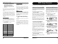
SAFETY PRECAUTIONS Usage Precautions
• Take care that no foreign objects (coins or pins etc.) or
liquids can enter the unit.
SAFETY PRECAUTIONS
In this manual, symbols are used to highlight warnings and
cautions for you to read so that accidents can be prevented.
The meanings of these symbols are as follows:
Caution
You should always turn off the power to the G7.1ut
and all other equipment before connecting or
disconnecting any cables. Also make sure to
disconnect all connection cables and the power cord
before moving the G7.1ut.
This symbol indicates explanations about
extremely dangerous matters. If users ignore this
Warning symbol and handle the device the wrong way,
serious injury or death could result.
This symbol indicates explanations about
dangerous matters. If users ignore this symbol and
handle the device the wrong way, bodily injury and
damage to the equipment could result.
Caution
Please observe the following safety tips and precautions to
ensure hazard-free use of the G7.1ut.
Connecting cables and input and output
jacks
Alterations
Warning
Never open the case of the G7.1ut or attempt to
modify the product in any way since this can result in
damage to the unit.
Volume
Caution
Do not use the G7.1ut at a loud volume for a long
time since this can cause hearing impairment.
Power requirements
Warning
• Be sure to use only an AC adapter which supplies 15 V
DC, 1.5A (Zoom AD-0012). The use of an adapter
other than the specified type may damage the unit and
pose a safety hazard.
• Connect the AC adapter only to an AC outlet that
supplies the rated voltage required by the adapter.
• When disconnecting the AC adapter from the AC outlet,
always grasp the adapter itself and do not pull at the
cable.
• During lightning or when not using the unit for an
extended period, disconnect the AC adapter from the
AC outlet.
• Do not pinch the power cord, bend it forcedly, or place
heavy objects on the power cord.
Environment
Warning
To prevent the risk of fire, electric shock or
malfunction, avoid using your G7.1ut in
environments where it will be exposed to:
•
•
•
•
•
Extreme temperatures
Heat sources such as radiators or stoves
High humidity or moisture
Excessive dust or sand
Excessive vibration or shock
Keep a minimum distance of 5 cm around the unit for
sufficient ventilation.
Do not impede the ventilation openings with objects
such as newspapers or curtains.
Usage Precautions
Caution
2
Using the Function Foot Switch.......... 34
Panel display ...................................... 14
Selecting a patch ............................... 14
Adjusting the sound ........................... 15
Using the Energizer ............................ 16
Other Functions ..................................... 46
Switching Modules On and Off With Your
Foot During Play (Manual Mode) ...... 18
Using the Internal Tuner
(Bypass/Mute Condition) ................... 20
Using the chromatic tuner ................. 20
Using other tuner types ..................... 22
Electrical interference
For safety considerations, the G7.1ut has been designed to
provide maximum protection against the emission of
electromagnetic radiation from inside the device, and
protection from external interference. However, equipment
that is very susceptible to interference or that emits powerful
electromagnetic waves should not be placed near the G7.1ut,
as the possibility of interference cannot be ruled out entirely.
Changing the Sound of a Patch
(Edit Mode) ......................................... 23
With any type of digital control device, the G7.1ut included,
electromagnetic interference can cause malfunctioning and
can corrupt or destroy data. Care should be taken to minimize
the risk of damage.
Storing/swapping patches ................ 27
Storing/swapping banks .................... 28
Returning patches to factory default
condition ........................................... 29
Patch configuration............................. 23
Basic edit mode steps ....................... 23
Changing a patch name ..................... 26
Storing Patches and Banks
(Store Mode) ....................................... 27
Using the Expression Pedal ................ 30
Cleaning
Use a soft, dry cloth to clean the G7.1ut. If necessary, slightly
moisten the cloth. Do not use abrasive cleanser, wax, or
solvents (such as paint thinner or cleaning alcohol), since
these may dull the finish or damage the surface.
Please keep this manual in a convenient place
for future reference.
About the built-in expression
pedal .................................................. 30
Assigning control targets to the
built-in expression pedal .................. 30
Adjusting the built-in expression
pedal................................................... 32
Using an external expression
pedal.................................................. 33
Specifying the tempo for a patch ...... 35
MIDI Usage Examples .......................... 37
What you can do with MIDI................ 37
Selecting the MIDI channel ................ 37
Sending and receiving patch switching
information via MIDI
(program change) ............................. 38
Sending and receiving pedal/switch/key
operation information via MIDI
(control change) ................................ 41
Sending and receiving G7.1ut internal
data via MIDI ..................................... 44
Using the ARRM function...................
Using the G7.1ut as audio interface
for a computer...................................
Muting the direct output when using
a USB connection .............................
About the editor/librarian software....
Adjusting the display contrast ...........
46
48
49
50
50
Linking Effects ...................................... 51
Switching between live performance
sound and direct recording sound ... 51
Using the Amp Select Function ......... 52
Changing the insert position of the
pre-amp section and WAH/EFX1
module ............................................... 52
Effect Types and Parameters .............. 54
How to read the parameter table....... 54
COMP module ........................................
WAH/EFX1 module .................................
ZNR module............................................
PRE AMP module ...................................
EQ module ..............................................
CABINET module....................................
MOD/EFX2 module.................................
DELAY module........................................
REVERB module .....................................
TOTAL module........................................
55
55
57
58
59
60
60
64
65
66
Troubleshooting.................................... 68
Specifications ....................................... 69
MIDI implementation chart................. 70
* MIDI is a registered trademark of Association of
Musical Electronics Industry(AMEI).
Handling
Warning
SAFETY PRECAUTIONS Usage
Precautions .......................................... 2
Features .................................................. 4
Terms Used in This Manual ................... 5
Controls and Functions ......................... 6
Getting Connected .................................. 8
Power-On ................................................ 9
Quick Guide 1 (Play Mode/Manual Mode
Operation) ........................................... 10
Quick Guide 2 (Edit Mode/Store Mode
Operation) ........................................... 12
Selecting Patches for Playing
(Play Mode) ........................................ 14
* Microsoft and Windows XP are registered trademarks of Microsoft Corporation.
* Macintosh is a registered trademark of Apple Computer.
* All other trademarks, product names, and company names mentioned in this document are the
property of their respective owners.
* Manufacturer names and product names mentioned in this document are trademarks or registered
trademarks of their respective owners. The names are used only to illustrate sonic characteristics and
do not indicate any affiliation with ZOOM CORPORATION.
• Never place objects filled with liquids, such as vases, on
the G7.1ut since this can cause electric shock.
• Do not place naked flame sources, such as lighted
candles, on the G7.1ut since this can cause fire.
• The G7.1ut is a precision instrument. Do not exert
undue pressure on the keys and other controls. Also
take care not to drop the unit, and do not subject it to
shock or excessive pressure.
ZOOM G7.1ut
ZOOM G7.1ut
3
Features
Terms Used in This Manual
Thank you for selecting the ZOOM G7.1ut (simply called the "G7.1ut" in this manual). The G7.1ut is a
sophisticated Multi Effect Processor with the following features.
● Latest technology for top performance
Excellent sound quality is assured by signal processing featuring 96 kHz/24 bit sampling and internal
32-bit processing. Frequency response remains flat to 40 kHz, and input converted noise is an amazing
-120 dB or better. The built-in USB port serves for direct connection to a computer. You can use the
G7.1ut as audio interface for the computer, allowing direct recording with the supplied DAW software.
● Versatile array of 92 effects
Out of a versatile palette of 92 effects, up to nine (including ZNR) can be used simultaneously. Recreate
the sound of famous amps and compact effects, use the 6-band guitar equalizer, or select from many
other great effects. The G7.1ut easily surpasses the usual feature complement in this class.
● Ready-to-go patches
Effect module combinations and settings can be stored and recalled as patches. The G7.1ut offers 80
preset patches that are ready to use right out of the box, plus 80 user patches which can be freely
rewritten, giving you a total of 160 choices. The muting interval when switching patches has been
reduced to less than 7 milliseconds, which makes for virtually seamless patch changes.
● Great for stage work or direct recording
The pre-amp section features two channels, and each distortion type has two dedicated algorithms, one
for live playing and one for direct recording. The CABINET effect simulates amp and mic recording
characteristics, and the algorithm is automatically switched according to the CABINET on/off setting.
An amp select feature matches the sound to the amp you are using. Connecting the G7.1ut to the power
amplifier input of the guitar amp is no problem: simply set the -10 dBm/+4 dBm switch to the +4 dBm
position.
● Built-in auto-chromatic tuner supports special tuning requirements
In addition to the standard auto-chromatic tuner, various other tuning methods are possible. The tuner is
designed to allow easy use on stage.
● Expression pedal supplied as standard
Adjust effect tone or volume in real time with the expression pedal that is built right into the unit. The
possibilities for creative play are endless. The CONTROL IN jack on the rear panel lets you connect an
external pedal (FP01/FP02) and use it as a dedicated volume pedal.
● Tube powered energizer
The tube-based Energizer shapes the analog output signal to produce that characteristic warm and
dynamic sound that is the hallmark of a tube amplifier.
● Programmable function switch
The user-programmable function switch further enhances flexibility and lets you optimize the unit for
any application. Use it to switch pre-amp channels, set the delay time, turn hold delay on and off, or for
various other tasks.
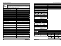
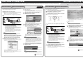
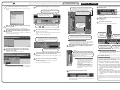
This section explains some important terms that are used throughout the G7.1ut documentation.
■ Effect module
As shown in the illustration below, the G7.1ut can be
thought of as a combination of several single effects.
Each of these is referred to as an effect module. In
addition to modules such as the compressor effect
module (COMP), amp simulator/distortion effect
module (PRE-AMP), and modulation effect module
(MOD/EFX2), the G7.1ut also provides a module for
ZNR (ZOOM Noise Reduction). Parameters such as
effect intensity can be adjusted for each module
individually, and modules can be switched on and off
as desired. The module series ZNR, PRE-AMP, EQ,
and CABINET operates as a virtual preamplifier
which is controlled with the knobs and keys on the
pre-amp section of the panel.
are read-only, and user groups (U, u) which can be
modified. Since each group comprises 40 patches,
groups A, b, U, and u offer a total of 160 patches.
In the G7.1ut, patches are called up four at a time
and selected with the foot switches. These four
patches are together referred to as a bank. There
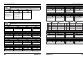
are ten banks in a group, numbered 0 through 9.
User groups
BANK 9
PATCH
BANK
BANK
00 1
BANK
BANK
BANK
0001
PATCH
BANK
PATCH
PATCH
BANK
BANK
100 1 2
PATCH111
PATCH
PATCH
PATCH
PATCH
PATCH
11 222 3
PATCH
PATCH
PATCH
BANK
0 1PATCH
PATCH
2
PATCH
PATCH
PATCH
222333 4
PATCH
PATCH
1PATCH
PATCH
2PATCH
PATCH
PATCH
PATCH
PATCH
333
PATCH
PATCH
PATCH
PATCH
2
PATCH
33 4444
PATCH
PATCH
PATCH
4
PATCH
4
PATCH
PATCH
3 44
PATCH
PATCH 4
Group U
Preset groups
BANK 9
PATCH
BANK
BANK
00 1
BANK
BANK
BANK
0001
PATCH
BANK
PATCH
PATCH
BANK
BANK
100 1 2
PATCH111
PATCH
PATCH
PATCH
PATCH
PATCH
11 222 3
PATCH
PATCH
PATCH
BANK
0 1PATCH
PATCH
2
PATCH
PATCH
PATCH
222333 4
PATCH
PATCH
1PATCH
PATCH
2PATCH
PATCH
PATCH
PATCH
PATCH
333
PATCH
PATCH
PATCH
PATCH
2
PATCH
33 4444
PATCH
PATCH
PATCH
4
PATCH
4
PATCH
PATCH
3 44
PATCH
PATCH 4
Group u
BANK 9
PATCH
BANK
BANK
00 1
BANK
BANK
BANK
0001
PATCH
BANK
PATCH
PATCH
BANK
BANK
100 1 2
PATCH111
PATCH
PATCH
PATCH
PATCH
PATCH
11 222 3
PATCH
PATCH
PATCH
BANK
0 1PATCH
PATCH
2
PATCH
PATCH
PATCH
222333 4
PATCH
PATCH
1PATCH
PATCH
2PATCH
PATCH
PATCH
PATCH
PATCH
333
PATCH
PATCH
PATCH
PATCH
2
PATCH
33 4444
PATCH
PATCH
PATCH
4
PATCH
4
PATCH
PATCH
3 44
PATCH
PATCH 4
Group A
BANK 9
PATCH
BANK
BANK
00 1
BANK
BANK
BANK
0001
PATCH
BANK
PATCH
PATCH
BANK
PATCH
BANK
1001111 2
PATCH
PATCH
PATCH
1 22 3
PATCH
PATCH
PATCH
1
PATCH
PATCH
PATCH
BANK
0 1 222
PATCH
PATCH
PATCH
PATCH
22 333 4
PATCH
PATCH
1PATCH
PATCH
2PATCH
PATCH
PATCH
PATCH
PATCH
333
PATCH
PATCH
PATCH
2PATCH
PATCH
33 4444
PATCH
PATCH
PATCH
4
PATCH
PATCH
PATCH
3 444
PATCH
PATCH 4
Group b
■ Effect type
Most effect modules comprise several different
effects which are referred to as effect types. For
example, the modulation effect module (MOD/
EFX2) comprises chorus, flanger, pitch shifter,
delay, and other effect types. Only one of these can
be selected at any time.
■ Modes
The G7.1ut has five different operation modes, as
listed below.
■ Effect parameter
All effect modules have aspects that can be
controlled. These are called effect parameters,
adjusted with the parameter knobs 1 – 4 on the panel.
When thinking of an effect module as a compact
effect, the parameters change the tone and effect
intensity similar to the knobs on the device.
● Manual mode
In this mode, you play your instrument while
using the foot switches to turn modules on and off.
● Play mode
In this mode, patches can be selected and played.
This is the default mode of the G7.1ut that is
always active when power is turned on.
● Edit mode
In this mode, the effect parameters of a patch can
be edited (changed).
■ Patch
In the G7.1ut, effect module combinations are stored
and called up in units referred to as patches. A patch
comprises information about the on/off status of each
effect module, about the effect type used in each
module, and about effect parameter settings.
Expression pedal settings and tempo settings are also
stored for each patch individually.
● Store mode
This mode serves for storing edited patches. It also
allows changing the store positions of patches.
● Bypass/mute mode
When the G7.1ut is in the bypass condition, effect
processing is temporarily turned off and only the
original sound is heard. In the mute mode, all
sound is turned off. The built-in tuner can be used
in either condition.
■ Bank and group
Patches are organized in preset groups (A, b) which
Please take the time to read this manual carefully, in order to get the most out of your G7.1ut and to ensure
optimum performance and reliability.
Channel B
INPUT
COMP
WAH/EFX1
ZNR
ZNR
Pre-amp section
PRE-AMP EQ
PRE-AMP EQ
CABINET
MOD/EFX2
DELAY
REVERB
OUTPUT
Channel A
4
ZOOM G7.1ut
ZOOM G7.1ut
5
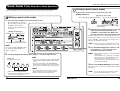
Controls and Functions
Controls and Functions
■ Control section
Top panel
■ Pre-amp section
■ Control section
■ Tube section
[GROUP/BANK]
indicator
Display
Parameter knobs
1–4
[TYPE] knob
[AMP SELECT/SYSTEM]
key
[PEDAL SETTING]
key
[BYPASS/TUNER] key
[EXIT] key
[PAGE] key [STORE/SWAP] key
■ Pre-amp section
BANK [W]/[Q]
foot switches
Foot switches 1 – 4
[FUNCTION] (CH A/B)
foot switch
[LEVEL] knob
[BASS] knob
[MIDDLE] knob
[TREBLE] knob
[PRESENCE] knob
[PRE-AMP A/B] keys
Expression pedal
Rear panel
[AMP TYPE] knob
[GAIN] knob
INPUT jack
POWER switch
-10 dBm/+4 dBm switch
OUTPUT R jack
OUTPUT L/MONO jack
AC IN connector
MIDI IN connector
MIDI OUT connector
PHONES jack
CONTROL IN jack
LEVEL knob
USB port
AUX IN jack
Effect module keys
■ Tube section
[TUBE] control
6
ZOOM G7.1ut
ZOOM G7.1ut
[BOOST] control
7
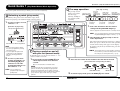
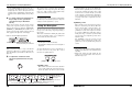
Getting Connected
Power-On
Refer to the examples shown below when making connections.
The steps for turning on the G7.1ut are described below.
1.
Connection example (1)
-10 dBm/+4 dBm switch
Use a monaural
shielded cable to
connect the guitar.
When connecting to the guitar input on the front panel
of a guitar amplifier, set the switch to "-10 dBm".
Use mono cables for connection to guitar amplifiers. When using
only one guitar amplifier, use the OUTPUT L/MONO jack.
Make sure that any connected guitar
amplifier is turned off.
In addition, fully turn down the volume control at
the guitar amplifier.
2.
Plug the AC adapter into an AC outlet
and plug the cable from the adapter
into the AC IN connector of the
G7.1ut.
3.
Use a monaural cable to connect the
guitar to the INPUT jack of the G7.1ut.
Connect optional expression
pedal (FP01/FP02)
Guitar
Guitar amplifiers
Expression pedal
4.
AC adapter
LEVEL knob
Use a monaural cable to connect the
OUTPUT L/MONO jack to the guitar
amplifier (when using one amplifier)
and the OUTPUT R jack to the second
guitar amplifier (when using two
amplifiers).
Headphones
Rhythm machine
MTR
Use a stereo Y adapter cable to connect a rhythm
machine (ZOOM RT-223 or similar) or a
CD/MD player or similar. The signal supplied to
the AUX IN jack is not processed by the internal
effects, it is supplied to the OUTPUT L/MONO
and OUTPUT R jacks as is. The signal is also
sent to the USB port.
Connection example (2)
Guitar
-10 dBm/+4 dBm switch
Computer
MIDI
interface
Patch switching and
pedal operation
information can be sent
and received as MIDI
messages.
By connecting the USB port to
a computer, the G7.1ut can be
used as an audio interface.
To monitor with headphones, plug the headphone
cable into the PHONES jack of the G7.1ut.
Turn power on in the following order:
G7.1ut → guitar amplifier(s)
HINT
The G7.1ut has a so-called "Amp Select" feature
that lets you match the unit to various kinds of
amplifiers. If necessary, select the appropriate
setting for your amplifier the first time you use the
G7.1ut (→ p. 52).
7.
To shut down the system, turn power
to the respective components off in
the reverse order than during powerup.
HINT
When the -10 dBm/+4 dBm switch on the rear
panel is set to "-10 dBm" and the LEVEL knob is
turned fully up, the G7.1ut has unity gain (output
level is the same as input level).
NOTE
When connecting to the power amplifier input on the
rear panel of a guitar amplifier, set the switch to "+4
dBm". The G7.1ut incorporates a feature for matching
its characteristics to the amplifier (amp select function).
For details, see page 52.
Guitar amplifier (rear panel)
8
HINT
5.
Rear panel
ZOOM G7.1ut
Proceed with care when powering up the system.
If you turn on power to the G7.1ut while the guitar
amplifier is already on, there is a risk of hearing
damage and damage to the speakers.
6.
Play your guitar and adjust the
volume control on the guitar amplifier,
on the guitar, and the LEVEL knob on
the rear panel of the G7.1ut to obtain
optimum listening volume.
ZOOM G7.1ut
9
Quick Guide 1 (Play Mode/Manual Mode Operation)
Quick Guide 1
(Play Mode/Manual Mode Operation)
Pre-amp operation
This section explains various basic steps, allowing you to use the G7.1ut right away.
The pre-amp section
allows you to adjust
distortion type,
intensity, and EQ for
two channels (A/B)
separately.
Selecting a patch (play mode)
Immediately after power-on, the unit will be in play mode,
which is for playing your instrument while selecting patches.
1. To select a patch, use foot
switches 1 – 4.
[Pre-amp section]
Distortion type
[AMP TYPE] knob
Pre-amp
module
output level
[LEVEL] knob
[GAIN] knob
Distortion
intensity
The key light shows which channel is currently selected.
U0
U0
HINT You can switch between channel A and B with
Patch name
the [FUNCTION] (CH A/B) foot switch (→ p. 34).
2. Turn the knobs of the pre-amp section to
AmpDrive ™LVL100
™LVL100
AmpDrive
LVL100
ÉBpmTp
ÉBpmTp
BpmTp
make adjustments.
The sound of the channel selected in step 1 changes.
When you operate a knob, the name of the parameter
and the current setting value appear on the display.
To return to play mode (or manual mode), press the
[EXIT] key.
Patch level
Function foot switch assignment
HINT
another group/bank, use
the BANK [W]/[Q] foot
switches to select the
group/bank and then use
foot switches 1 – 4.
HINT You can switch the
group/bank by turning the
[TYPE] knob.
10
[TREBLE] knob
High range
boost/cut
setting with the [PRE-AMP A/B] keys.
Group name/Bank number
2. To select a patch from
[BASS] knob
Low range
boost/cut
Ultra-high
range boost/cut
[PRESENCE] knob
1. Select the channel for which to make a
[Indication in play mode]
• You can switch patches within
the same group/bank by turning
parameter knob 1.
• You can adjust the patch level
(output level of the individual
patch) by turning parameter
knob 2.
Mid range
boost/cut
[MIDDLE] knob
NOTE The changes that you have made to a patch will
Turning a module on and off
with your foot (manual mode)
be lost when you select another patch. To keep
the changes, store the patch first (→ p. 13).
In manual mode, you can use foot switches 1 – 4 to
switch a module on and off.
1. In play mode, keep the BANK [W] foot
2. Press the foot switch for the module to be switched on and off.
switch depressed for more than one
second.
The G7.1ut switches to manual mode.
NOTE
In manual mode, the foot switches do not select
patches. However, the [TYPE] knob (group/bank
selection) and parameter knob 1 (patch selection)
function the same as in play mode. Please note that
you go back to "play mode" when you change
patches.
ZOOM G7.1ut
[Foot switch and corresponding modules]
WAH/EFX1 module
MOD/EFX2 module
PRE-AMP module
DELAY module
3. To return to play mode, press the BANK [W] foot switch.
ZOOM G7.1ut
11
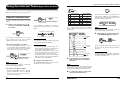
Quick Guide 2 (Edit Mode/Store Mode Operation)
Quick Guide 2 (Edit Mode/Store Mode Operation)
This section explains how to edit a selected patch and how to store the changes you have made.
Storing a patch (store mode)
1. In play mode, manual mode, or edit mode, press the
[STORE/SWAP] key.
[Display in store mode]
Editing a patch (edit mode)
Store target group name/bank number
1. Press the effect module key for the module to edit.
U0
The unit switches to edit mode.
By repeatedly pressing the effect
module key, the respective
module can be toggled between
on and off.
2. The indication "PATCH" appears in the top
right of the display and the indication
"STORE?" in the bottom left. Make sure
that the operation is what you intend to do.
In this condition, you can store individual patches. If
the display is different, use parameter knob 2 to bring
up the "STORE?" indication and parameter knob 3 to
bring up the "PATCH" indication.
Effect type name
MOD:Chorus
¡Depth
=100 é
Depth
Parameter value
Parameter number/Parameter name
HINT
NOTE
foot switches 1 – 4 to select the store
target bank and patch number.
NOTE • Only user group patches can be specified as
2. Use the [TYPE] knob and parameter knobs 1 – 4 to make adjustments.
store target.
• When a patch from a user group is selected,
this patch becomes the default store target.
• When a patch from a preset group is
selected, the first user group patch becomes
the default store target.
HINT
• The effect type (distortion type) of the PRE-AMP
module can be changed with the [AMP TYPE]
knob.
• The major parameters of the PRE-AMP/EQ
module can be edited with the knobs of the preamp section, in the same way as in play mode.
4. Press the [STORE/SWAP] key once more.
The store process is carried out, and the unit returns to
play mode.
NOTE
Parameter knobs 1 – 4
Change the respective parameter.
For information on parameters assigned
to the knobs, see page 55 – 67.
12
In store mode, you can swap patches as well
as store and swap entire banks (→ p. 27 – 28).
3. Use the BANK [W]/[Q] foot switches and
If you press the PRE-AMP/EQ module
key, the display will be different. For
details, see page 24.
[TYPE] knob
Changes the effect type.
:PATCH
NEWDrive £:PATCH
™STORE?
STORE?åU0-1
U0-1 é
™STORE?åU0-1
Store target group name, bank number,
patch number
[Display in edit mode ]
Module name
Store source patch name
The changes that you have made to a patch
will be lost when you select another patch. To
keep the changes, store the patch first.
ZOOM G7.1ut
HINT
ZOOM G7.1ut
You can return the user group patches easily
to the factory default settings (→ p. 29).
13
Selecting Patches for Playing (Play Mode)
Selecting Patches for Playing
(Play Mode)
HINT
Immediately after you turn on the G7.1ut, it is always in the mode for selecting and using patches (play
mode). The most recently used patch is automatically called up again. The various operation steps in play
mode are described in this section.
In play mode, the following information is shown
on the panel.
Panel display
Group name (A, b, U, u)
Shows the number of the
Groups A and b are read-only groups
parameter knob that
(preset groups). Groups U and u are
controls the patch level.
read/write enabled groups (user groups).
A0
NewDrive ™LVL100
LVL100
ÉBpmTp
BpmTp
é
Patch name
Bank number (0 – 9)
• In play mode, you can select a patch by turning
parameter knob 1.
• When you press a foot switch whose LED is lit,
the same patch is called up once more.
2.
To switch to a patch in another bank,
use the BANK [W]/[Q] foot switches
to change the bank and then use foot
switches 1 – 4 to select the patch.
Adjusting the sound
In play mode, you can use the knobs on the panel
to adjust the basic parameters of the pre-amp
section (distortion type and intensity, EQ boost/
cut etc.).
1.
In play mode, select the patch.
2.
Press one of the [PRE-AMP A/B] keys
to select the pre-amp channel A or B
for which to make the adjustment.
Patch level
Shows the output level setting
(2 – 100) for the currently
selected patch
"E" symbol
If the currently displayed setting
value differs from the original
patch setting, the indication "E"
(for "Edited") appears.
Function foot switch assignment
Shows the function assigned to the function foot switch (→ p. 34).
BANK [W]/[Q]
foot switches
Foot switches
1–4
When you repeatedly press the BANK [Q] foot
switch, the G7.1ut switches the group/bank as
follows.
[PRE-AMP A/B] keys The key for the channel (A or B) that is currently
selected for the pre-amp section is lit.
User groups
HINT
Preset groups
A0
A1
The pre-amp section of the G7.1ut has two
separate channels which allow individual settings.
Simply pressing one of the [PRE-AMP A/B] keys
instantly switches the channel.
A9
B0
B9
You can switch between channel A and B with the
[FUNCTION] (CH A/B) foot switch (→ p. 34).
3.
HINT
Effect module Keys for modules that are active in the
keys
currently selected patch are lit in red.
Foot switch The LED of the foot switch for the currently
1 – 4 LEDs selected patch is lit.
Selecting a patch
This section explains how to select a patch in play
mode.
1.
14
Press a foot switch 1 – 4 whose LED
is not lit.
In play mode, you can switch the group/bank by
turning the [TYPE] knob.
NOTE
• When using the BANK [W]/[Q] foot switches to
change banks, press and release the switch
quickly.
• If you keep the BANK [W] foot switch depressed
for more than one second, the G7.1ut switches
to manual mode (→ p. 18).
• If you keep the BANK [Q] foot switch depressed
for more than one second, the G7.1ut switches
to the bypass condition (effects off). If you keep
the switch depressed further, the G7.1ut
switches to the mute condition (original sound
and effect sound both off) (→ p. 20).
The LED of the pressed switch lights up,
indicating that a new patch has been called up.
ZOOM G7.1ut
ZOOM G7.1ut
To change the distortion type, turn
the [AMP TYPE] knob.
The [AMP TYPE] knob selects the distortion type
(the amp or compact effect that is being
simulated). When you turn the knob, the name of
the new amp type appears on the display.
PRE-AMP œ–ø–––
FD Clean é–œ–œµµ
[AMP TYPE]
knob
Type name
"E" symbol
HINT
• When you have changed the distortion type, the
"E" symbol appears on the display, and the
[STORE/SWAP] key lights up.
• If the currently displayed setting value differs
from the original patch setting, the indication "E"
(for "Edited") appears.
15
Selecting Patches for Playing (Play Mode)
• The lit [STORE/SWAP] key indicates that one or
more items (including items not currently
displayed) have been changed from the
contents of the original patch. If all items are
returned to their original settings, the key will go
out.
The patch level is a parameter that controls the
output level of the respective patch. The setting
range is 2 – 100. A setting of 80 results in unity
gain (no level increase or decrease).
NOTE
4.
To change other major parameters in
the pre-amp section, operate the
respective knob (see illustration
below).
When you turn a knob, the name and the current
setting of the respective parameter appear on the
display. Operating the [BASS], [MIDDLE],
[TREBLE], or [PRESENCE] knob will boost or
cut the respective band, and the setting is reflected
in the graph on the right side of the display.
Name of currently adjusted parameter
Presence œ–ø–––
-12dB
é–œ–œµµ
The changes that you have made to a patch will be
lost when you select another patch. To keep the
changes, store the patch first (→ p. 27).
counterclockwise, the effect is off. Turning the
knob clockwise gradually increases the tube
circuit gain, resulting in warmer, more solid
crunch or drive sound. Normally, you should
set the control to a position where distortion is
not too audible, but you can set it higher when
you purposely want to emphasize the tube
distortion.
● [BOOST] control
Using the Energizer
The G7.1ut incorporates an Energizer function
that processes the analog output signal using a
tube circuit.
This feature is suitable for making the guitar stand
out in an ensemble setting, or for adding that
characteristic tube distortion sound.
HINT
Parameter value Graphic representation of
boost/cut setting in each band
• The Energizer is active in all modes.
• The Energizer settings are not stored as part of
the patch.
This control boosts specific frequency bands to
make the sound more pronounced. When the
knob is turned fully counterclockwise, the
effect is off. Turning the knob clockwise
gradually boosts the low frequencies and the
area around 2 kHz. Especially when using a
small guitar amp or an audio system with flat
response, this can be helpful to produce more
dynamic sound.
The [BOOST] control is useful in such
situations, and for bringing the sound of the
guitar more to the foreground when playing in
a band.
NOTE
HINT
When you perform step 3 or step 4, the G7.1ut
switches to edit mode. To return to play mode,
press the [EXIT] key. (For details on edit mode, see
page 23.)
5.
Selecting Patches for Playing (Play Mode)
To adjust the Energizer, use the control knobs of
the tube section on the panel. The control
functions are explained below.
To adjust the overall level of the
patch, turn parameter knob 2 in play
mode.
[TUBE] control
• The intensity of the distortion achieved with the
[TUBE] control depends on the guitar and type
of pickup.
• When both controls are fully turned up, the
volume level will be higher and excessive
distortion may occur.
[BOOST] control
● [TUBE] control
This control adds characteristic tube distortion
to the sound, making the guitar stand out more
distinctly. When the knob is turned fully
[PRESENCE] knob
Ultra-high range
boost/cut
[GAIN] knob
Distortion intensity
[LEVEL] knob
Pre-amp module output level
16
[TREBLE] knob High range boost/cut
[MIDDLE] knob Mid range boost/cut
[BASS] knob Low range boost/cut
ZOOM G7.1ut
ZOOM G7.1ut
17
Switching Modules On and Off With Your Foot During Play (Manual Mode)
Switching Modules On and Off With Your Foot During Play (Manual Mode)
module.
1.
In play mode, select a patch.
2.
Press and hold the BANK [W] foot
switch for at least 1 second.
Hold down for 1 second
or more
The LED of the BANK [W] foot switch lights up
and the G7.1ut switches to manual mode.
Shows the number of the
parameter knob that controls
the patch level.
Patch level
Shows the output
level of the currently
selected patch.
In manual mode, the following information
appears on the panel (see illustration below).
NOTE
In manual mode, you cannot use the foot switches
to select patches. However, the [TYPE] knob
(group/bank selection) and the parameter knob 1
(patch selection) operate in the same way as in
play mode. Please note that you go back to "play
mode" when you change patches.
3.
"E" symbol
If the currently displayed
setting value differs from
the original patch setting,
the indication "E" (for
"Edited") appears.
In manual mode, you can use foot switches 1 – 4
to switch the major effect modules on or off. The
module/switch allocation is as follows.
To switch a module between on and
off, press the foot switch for that
Foot switch 1
Foot switch 3
WAH/EFX1
MOD/EFX2
module
module
Foot switch 2
Foot switch 4
PRE-AMP
DELAY
module
module
[PRE-AMP A/B] keys
The key for the channel (A or B) that is
currently selected for the pre-amp section is lit.
HINT
LVL100
NewDrive ™LVL100
ÉBpmTp
BpmTp
é
Function foot switch
assignment
Shows the function
assigned to the function
foot switch (→ p. 34).
NOTE
The changes that you have made to a patch will be
lost when you select another patch. To keep the
changes, store the patch first (→ p. 27).
The condition where foot switches 1 – 4 are used to switch the major modules in a patch on and off
individually is called "manual mode". In this mode, the single effects of the G7.1ut can be controlled with
your foot like independent compact effects.
Effect module keys
Keys for modules that are active in the
currently selected patch are lit in red.
• When a module is switched on/off, the [STORE/
SWAP] key lights up.
• In manual mode, you can use the knobs on the
panel as in play mode to adjust pre-amp
parameters, patch level, and the tube energizer.
For an explanation of operation procedures, see
"Adjusting the sound" in the section on play
mode (→ p. 15).
• From manual mode you can switch to edit mode
for editing patches. For details on edit mode,
see page 23.
4.
To return to play mode, press the
BANK [W] foot switch.
BANK [W] foot switch LED
This is always lit when the G7.1ut is in manual mode. When you press this
foot switch in manual mode, the unit returns to play mode.
Foot switch 1 - 4 LEDs
When the module for the respective foot switch is on, the respective LED is lit.
18
ZOOM G7.1ut
ZOOM G7.1ut
19
Using the Internal Tuner (Bypass/Mute Condition)
Using the Internal Tuner (Bypass/Mute Condition)
The G7.1ut incorporates a tuner function that supports regular chromatic tuning as well as special tuning.
This section explains the steps for using the tuner.
E
Note
Using the chromatic tuner
1.
In play mode, manual mode, or edit
mode, press and hold the BANK [Q]
foot switch.
Release switch when "MUTE"
is shown
After "BYPASS" or "MUTE" was shown, the
display automatically switches to the tuning
display.
Tuner type
BYPASS
Release switch when
"BYPASS" is shown
™CHROMATC
CHROMATC £440Hz
440Hz
>>˙<
> ˙
> ˙
> ˙
>>˙
>>˙<
˙<
˙ <
˙ <
˙ <
NOTE
You can switch to the mute condition by pressing
and holding the [BYPASS/TUNER] key.
HINT
• The built-in expression pedal functions as a
volume pedal in the bypass condition (in the
mute condition, the pedal has no effect).
• By turning the parameter knob 2, you can select
other tuner types besides the chromatic tuner.
For more information, see the next section.
• The number shown in reverse on the display
indicates that the corresponding parameter
knob can be used for adjustment.
3.
2.
HINT
You can switch to the bypass condition by
pressing the [BYPASS/TUNER] key.
Play the open string to tune.
The [GROUP/BANK] indicator shows the note
which is closest to the current pitch.
CHROMATC £442Hz
442Hz
™CHROMATC
>˙<
>
HINT
When the G7.1ut is turned off and on again, the
reference pitch will be reset to 440 Hz.
5.
When tuning is completed, press one
of the BANK [W]/[Q] foot switches.
Pitch is
low
Pitch is
correct
The G7.1ut returns to the previous mode. If the
G7.1ut was in edit mode, it will be switched to
play mode.
HINT
Pitch is
high
The bypass/mute condition can be canceled by
pressing the [BYPASS/TUNER] key, [EXIT] key, or
one of the foot switches 1 – 4.
Tune the string of your instrument
while checking the note and pitch
indication.
HINT
First you should perform rough tuning to bring up
the desired note indication, and then watch the
lower part of the display and fine tune the pitch.
● To switch to the mute condition
Hold the BANK [Q] foot switch until the
indication "BYPASS" changes to "MUTE".
Then release the foot switch. The G7.1ut is
now in the mute condition.
20
After the G7.1ut is turned on, the tuner reference
pitch is always "440 Hz (center A = 440 Hz). The
adjustment range using parameter knob 3 is center
A = 435 – 445 Hz, in 1-Hz steps.
Reference pitch
● To switch to the bypass condition
Hold the BANK [Q] foot switch for about 1
second, until the indication "BYPASS" appears
on the display. Then release the foot switch.
The G7.1ut is now in the bypass condition.
D
EB
E
F
GB
G
The > < symbols in the lower part of the display
show by how much the pitch differs from the
displayed note.
™CHROMATC
CHROMATC £440Hz
440Hz
>>˙<
To use the tuner, the G7.1ut must be set to the
bypass condition (effects off) or mute condition
(original sound and effect sound both off).
[GROUP/BANK]
[GROUP/BANK]
Note
indicator
indicator
AbB
A
BB
B
C
DB
MUTE
To use the chromatic tuner function, proceed as
follows.
Note
4.
ZOOM G7.1ut
To change the reference pitch of the
tuner, turn parameter knob 3.
ZOOM G7.1ut
21
Using the Internal Tuner (Bypass/Mute Condition)
setting "b" (one semitone lower), "bb" (two
semitones lower), and "bbb" (three semitones
lower).
Using other tuner types
Besides chromatic tuning, the G7.1ut offers
various other tuning types such as standard tuning
for guitar and bass, open tuning, etc. To use these
functions, proceed as follows.
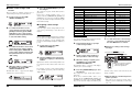
Changing the Sound of a Patch (Edit Mode)
The condition where you can change the effect types and settings that make up a patch is called "edit
mode". This section describes how to use this mode.
Optional tuning to 1 - 3 semitones lower
™GUITAR
GUITAR
>>˙<<
£
¢Str1
Str1
Patch configuration
Basic edit mode steps
1.
Switch the G7.1ut to the bypass or
mute condition as described in step 1
of "Using the chromatic tuner".
The display shows the tuning indication.
HINT
2.
4.
Turn parameter knob 2 to select the
tuner type.
The available tuner types and the corresponding
note names for each string are listed below.
If you select "OPEN A" as tuner type, the
[GROUP/BANK] indicator and display indication
will be as follows.
DB
Tuner type
Reference pitch
™OPEN
OPEN A
>>˙<<
£440Hz
440Hz
¢Str2
Str2
Correct note for selected string
String number
3.
If necessary, turn parameter knob 3
to change the reference pitch of the
tuner.
The setting range is center A = 435 – 445 Hz, in
1-Hz steps.
When the G7.1ut is turned off and on again, the
reference pitch will be reset to 440 Hz.
Play the open string of the indicated
number and adjust the pitch.
5.
Turn parameter knob 4 to switch to
other strings.
6.
Tune other strings in the same way.
7.
When tuning is completed, press one
of the BANK [W]/[Q] foot switches.
The G7.1ut returns to the previous mode. If the
G7.1ut was in edit mode, it will be switched to
play mode.
HINT
When the G7.1ut is turned off and on again, the
tuner type setting will be reset to the default
(chromatic tuner).
If "GUITAR" or "BASS" has been selected as
tuner type, turning parameter knob 3 further
anticlockwise from the "435" setting selects the
As shown in the "Patch configuration" illustration
below, the G7.1ut can be thought of as a series of
several single effects (effect modules). A
combination of these modules and the settings for
each module are stored as a patch.
The basic steps that are normally taken in edit
mode are explained here. For details on effect
types and parameters for each module, see the
section "Effect Types and Parameters" on page 54
– 67.
Almost all modules comprise several different
effects (called effect types), one of which is
selected at any given time. For example, the
MOD/EFX2 module allows selection of either
CHORUS, PITCH SHIFTER, DELAY, etc.
1.
The elements that determine the sound of a patch
are called effect parameters. Each effect type has
its own parameters that can be controlled with
knobs on the panel. Even within the same module,
when the effect type is different, the effect
parameters that can be controlled will also be
different.
2.
Select the patch to edit.
The patch can be from a preset group (A/b) or
user group (U/u). However, if you have edited a
patch from a preset group, it can only be stored in
a user group (→ p. 27).
In play mode or manual mode, press
the effect module key (see illustration
on next page) to select the module on
which to operate.
The G7.1ut switches to edit mode, and the display
changes as follows.
[Module other than PRE-AMP/EQ]
In the module configuration shown below, the
ZNR, PRE-AMP, EQ, and CABINET modules
operate as a virtual pre-amp section. Depending
on the application, this section can be inserted
after the WAH/EFX1 module or after the DELAY
module (→ p. 52). For the ZNR, PRE-AMP and
EQ modules, different settings can be made in
two channels (A/B).
Module name
Effect type name
MOD:Chorus
¡Depth
Depth
=100
Parameter
number
Currently selected
parameter and its setting
value
HINT
Tuner type
STR1
STR2
STR3
String
number STR4
STR5
STR6
STR7
22
GUITAR
BASS
E
B
G
D
A
E
B
G
D
A
E
B
OPEN A
E
DB
A
E
A
E
OPEN G
OPEN E
D
B
G
D
G
D
E
B
AB
E
B
E
OPEN D
D
A
GB
D
A
D
• On every display screen, the number shown in
reverse indicates the parameter knob that can
be used to adjust the parameter.
DADGAD
D
A
G
D
A
D
[Patch configuration]
Pre-amp section
Channel B
INPUT
COMP
WAH/EFX1
ZNR
ZNR
PRE-AMP
PRE-AMP
EQ
EQ
CABINET
MOD/EFX2
DELAY
REVERB
Channel A
ZOOM G7.1ut
ZOOM G7.1ut
23
Changing the Sound of a Patch (Edit Mode)
Changing the Sound of a Patch (Edit Mode)
the knobs and keys are listed in Figure 1 below.
Effect module keys
MOD:Chorus
¡Depth
= 80 é
[COMP] key
[ZNR] key
[WAH/EFX1] key
[EQ] key
[PRE-AMP] key
• The effect module keys for modules that are ON
in the currently selected patch are lit in red (keys
for modules that are OFF are not lit). When you
press a key to select a module, the key color
changes to orange (or to green if the module is
off).
[PRE-AMP module ]
PRE-AMP œ–ø–––
FD Clean é–œ–œµµ
Effect type name
[MOD/EFX2] key
[CABINET] key
Simplified graphical
representation of EQ
settings
[EQ module ]
Equalizer ––––––
Off
––––––
[REVERB] key
[DELAY] key
[TOTAL/FUNCTION] key
HINT
• If any module on/off status, effect type
selection, or a parameter setting value has been
changed at least once, the [STORE/SWAP] key
lights up and the indication "E" appears next to
the item.
• The "E" indication disappears when the item is
returned to the original value. However, if any
other item has been changed, the [STORE/
SWAP] key remains lit.
NOTE
The PRE-AMP, ZNR, and EQ modules can be set
to on or off separately for each channel (A/B).
4.
When the effect module key [PRE-AMP]/[EQ]
is selected, parameter knobs 1 – 4 can be used
to adjust other parameters of the PRE-AMP/EQ
module. The functions of the knobs are listed in
Figure 2 below.
To edit the selected module, proceed
as follows.
Number of operated
parameter knob and
parameter name
Parameter value
HINT
For effect modules with only one effect type (EQ
module, CABINET module etc.), the effect type
cannot be changed.
● When PRE-AMP/EQ module is selected
The PRE-AMP and EQ module parameters can
always be adjusted with the knobs and keys of
the pre-amp section, regardless of which
module is currently selected. The functions of
HINT
• When the PRE-AMP parameter of the pre-amp
section is adjusted, the PRE-AMP module is
automatically selected and the [PRE-AMP] key
lights up in orange. When an EQ parameter is
adjusted, the EQ module is automatically
selected and the [EQ] key lights up in orange.
• The PRE-AMP, ZNR, and EQ modules allow
separate parameter settings for the two
channels (A/B). Select the channel first, and then
adjust the parameter.
Figure 1
[Editing PRE-AMP/EQ module with pre-amp section]
[PRE-AMP A/B] keys
Select one of the two channels of the pre-amp section.
● When a module other than PRE-AMP/
NOTE
• If edit mode was activated from play mode, foot
switches 1 – 4 can be used to switch patches.
However, note that editing changes will be lost
when switching patches during editing.
• When edit mode was activated from manual
mode, the foot switches 1 – 4 can be used to
switch a specific module on or off.
EQ is selected
Switch the effect type as needed with the
[TYPE] knob (for modules having several
effect types), and use the parameter knobs 1 – 4
the adjust the parameters of the effect type.
Which parameters are assigned to the
parameter knobs 1 – 4 differs, depending on the
module and effect type (→ p. 54 – 67).
3.
To switch the selected module
between on and off, press the same
module key once more.
When the module is off, the indication "Module
Off" is shown on the display. Pressing the same
key once more in this condition switches the
module on.
[TYPE] knob
Parameter knobs 1 - 4
When you turn a parameter knob, the display
changes as follows.
[GAIN] knob
Adjusts the gain
(distortion intensity) of
the PRE-AMP module.
[AMP TYPE] knob
Selects the distortion
type of the PRE-AMP
module.
[BASS] knob
Adjusts the low
range boost/cut of
the EQ module.
[LEVEL] knob
Adjusts the output
level of the PRE-AMP
module.
ZOOM G7.1ut
[PRESENCE] knob
Adjusts the ultra-high
range boost/cut of the
EQ module.
[MIDDLE] knob
Adjusts the mid range
boost/cut of the EQ
module.
Figure 2
[Editing PRE-AMP/EQ module with parameter knobs 1 – 4 ]
TONE parameter
Adjusts the tonal
quality of the PREAMP module.
PRE-AMP CHAIN parameter
Selects the insert position of
the pre-amp section.
24
[TREBLE] knob
Adjusts the high
range boost/cut of
the EQ module.
ZOOM G7.1ut
HARMONICS parameter
Adjusts the harmonics
component of the EQ
module.
LO-MID parameter
Adjusts the lower mid range
boost/cut of the EQ module.
25
Changing the Sound of a Patch (Edit Mode)
5.
Repeat steps 2 – 4 to edit other
modules in the same way.
6.
When editing is finished, press the
[EXIT] key.
¡:0
:0 ™:A
:A £:@
:@ ¢:çå
çå
NAME:[±ewDrive]
NAME:[
ewDrive]
The alternating black square ( ) indicates
that this character can be changed
The G7.1ut returns to the previous mode.
NOTE
• The changes that you have made to a patch will
be lost when you select another patch. To keep
the changes, store the patch first (→ p. 27).
• The patch level (output level of individual patch)
cannot be changed in edit mode. Use play mode
or manual mode to set the level.
3.
Turn parameter knob 4 to move the
character input position, and use
parameter knobs 1 – 3 to select the
new character.
Parameter knobs 1 – 3 select characters as
follows.
Parameter knob 1 (numerals): 0 – 9
Parameter knob 2 (letters): A – Z, a – z
Parameter knob 3 (symbols):(space)
$
HINT
• If edit mode was entered from play mode, you
can return to play mode by pressing the BANK
[W]/[Q] foot switches or foot switches 1 – 4. In
this case, the bank/patch will be switched at the
same time.
• If edit mode was entered from manual mode,
you can cancel the mode by pressing the BANK
[W] foot switch. The G7.1ut will then return to
manual mode.
4.
Repeat step 3 until the patch name is
as desired. Then press the [EXIT] key.
This section explains how to use the store mode. In store mode, you can store edited patches in memory, or
swap the store location of user group patches. Storing and swapping can also be carried out for entire
banks. The patches of the user groups can be returned to the factory default condition at any time.
the display.
Storing/swapping patches
1.
In play mode, manual mode, or edit
mode, press the [STORE/SWAP] key.
3.
The G7.1ut switches to the store standby
condition, and the currently selected patch
becomes the store/swap source.
The [GROUP/BANK] indicator shows the store/
swap target group name and bank number.
:PATCH
NEWDrive £:PATCH
™STORE?
STORE?åU0-1
U0-1 é
Store/swap target
group name/bank
number
Store/swap target
group name, bank number,
patch number
HINT
• In the factory default condition, the user groups
(U, u) contain the same patches as the preset
groups (A, b).
• If a patch has been edited, it will be stored or
swapped in the edited condition.
• If a patch from a preset group was selected
In play mode, manual mode, or edit
mode, press the [TOTAL/FUNCTION]
effect module key.
NOTE
When "BANK" is shown, the subsequent operation
will be carried out for the entire bank. Make sure
that the correct indication is shown.
U0
You can change the name of an edited patch. To
do this, proceed as follows.
NEWDrive £:PATCH
:PATCH
™STORE?
STORE?åU0-1
U0-1 é
This section explains how to store and swap
patches.
Indicates that the patch was edited.
Store/swap source patch name
Changing a patch name
1.
Storing Patches and Banks (Store Mode)
The first character of the patch name is shown
alternating with a black square.
Turn parameter knob 2 to bring up the
indication "STORE?" or "SWAP?" on
the display.
NEWDrive £:PATCH
:PATCH
™STORE?
STORE?åU0-1
U0-1 é
When "STORE?" is selected, the current patch
can be stored as any user patch.
When "SWAP?" is selected, the current user
patch can be swapped with any other user patch.
NOTE
If the source patch is from a preset group, the
indication "SWAP?" does not appear.
4.
Use the [TYPE] knob or BANK [W]/
[Q] foot switches to select the store/
swap target group name/bank
number.
when you pressed the [STORE/SWAP] key,
the first user group patch will automatically be
selected as store target.
2.
26
2.
Turn the [TYPE] knob to bring up the
patch name on the lower part of the
display.
ZOOM G7.1ut
To store/swap individual patches,
turn parameter knob 3 to bring up the
indication "PATCH" in the top right of
ZOOM G7.1ut
or
BANK [W]/[Q]
foot switches
27
Storing Patches and Banks (Store Mode)
5.
Use parameter knob 1 or the foot
switches 1 – 4 to select the store/
swap target patch number.
or
Foot switches 1 - 4
6.
Press the [STORE/SWAP] key once
more.
The store/swap process is carried out, and the
G7.1ut then returns to the play mode or manual
mode with the store/swap target patch being
selected.
By pressing the [EXIT] key instead of the
[STORE/SWAP] key, you can cancel the process
and return to the previous mode.
NOTE
The Energizer settings are not stored as part of the
patch.
Storing/swapping banks
This section explains how to store and swap entire
banks.
1.
In play mode, manual mode, or edit
mode, press the [STORE/SWAP] key.
The G7.1ut switches to the store standby
condition, and the currently selected bank
becomes the store/swap source.
2.
28
Storing Patches and Banks (Store Mode)
Store/swap source group name/bank number
U1
:BANK
BANK U0 £:BANK
™STORE?
STORE?åU1
U1
é
Store/swap
target group
name/bank number
Store/swap
target group
name/bank number
3.
Turn parameter knob 2 to bring up the
indication "STORE?" or "SWAP?" on
the display.
When "STORE?" is selected, the current bank can
be stored as any user bank.
When "SWAP?" is selected, the current user bank
can be swapped with any other user bank.
NOTE
Returning patches to
factory default condition
Even if you have made changes to the user group
patches, you can return all patches to the factory
default condition at any time. To do this, proceed
as follows.
1.
The indication "All Initialize?" appears on the
display.
If the source bank is from a preset group, the
indication "SWAP?" does not appear.
4.
Use the [TYPE] knob or BANK [W]/
[Q] foot switches to select the store/
swap target bank.
5.
Press the [STORE/SWAP] key once
more.
The store/swap process is carried out, and the
G7.1ut then returns to play mode or manual mode
with the store/swap target bank being selected.
By pressing the [EXIT] key instead of the
[STORE/SWAP] key, you can cancel the process
and return to the previous mode.
Turn power to the G7.1ut on while
holding down the [STORE/SWAP] key.
All Initialize?
Y:STORE N:EXIT
2.
Press the [STORE/SWAP] key once
more.
All patches are returned to the factory default
condition, and the G7.1ut switches to play mode.
By pressing the [EXIT] key before performing
step 2, you can cancel the process.
To store/swap entire banks, turn
parameter knob 3 to bring up the
indication "BANK" in the top right of
the display.
ZOOM G7.1ut
ZOOM G7.1ut
29
Using the Expression Pedal
Using the Expression Pedal
This section explains how to use the built-in and an external expression pedal.
About the built-in
expression pedal
The G7.1ut has an integrated expression pedal
that can be used to control specific effect
parameters in real time.
The pedal has four control targets (PDL1 –
PDL4), which makes it possible to adjust up to
four parameters simultaneously. A setting
example is shown below, to give you an idea of
how the pedal can be used.
Control target parameters
● PDL1
PRE-AMP module
4.
To assign a control target to the built-in
expression pedal, proceed as follows.
1.
HINT
The parameters to be controlled by the built-in
expression pedal and the setting range can be set
separately for each patch.
2.
Press the [PEDAL SETTING] key.
The display changes as follows.
Control target indication
(PDL1 - PDL4)
HINT
• The parameter adjustment range covered by the
pedal can be set for each control target
separately.
• In bypass mode, the built-in expression pedal
functions as a volume pedal. (In mute mode, the
pedal has no effect.)
30
Control target
parameter name
¡PDL1=Resonance
PDL1=Resonance
WAH:AutoWah
Module name
Effect type name
Feed Back
Mix
Minimum value
■ When parameter knob 3 is operated
PDL :Target1 é
£MAX=100
MAX=100
As you turn parameter knob 1, the effect
parameter, effect type, and effect module
changes.
HINT
● PDL3
DELAY module
● PDL4
REVERB module
PDL :Target1 é
™min=50
min=50
Turn parameter knob 1 to select the
parameter that is to be controlled.
In play mode, select the patch.
Rate
Expression
pedal
■ When parameter knob 2 is operated
Assigning control targets
to the built-in expression
pedal
Gain
● PDL2
MOD/EFX2 module
The subsequent operation steps are the same for
PDL1 – PDL4.
HINT
The expression pedal setting is included in the
TOTAL/FUNCTION module for the respective
patch. The above display can also be called up by
pressing the [TOTAL/FUNCTION] effect module
key and turning the [TYPE] knob.
3.
Turn the [TYPE] knob to select one of
the four control targets (PDL1 –
PDL4).
• For information on which parameters can be
selected as control targets, see “Effect Types
and Parameters” on page 54 – 67.
• When “Volume” is selected as control target, the
built-in expression pedal functions as a volume
pedal.
• When “NOT Assign” is displayed, no parameter
is assigned to the current control target. By
setting all four control targets to “NOT Assign”,
the expression pedal can be defeated.
NOTE
If you select “NOT Assign”, steps 5 and 6 cannot
be carried out.
5.
To set the adjustment range for the
parameter to be controlled, use
parameter knob 2 (minimum value)
and parameter knob 3 (maximum
value).
The settings selected with parameter knobs 2 and
3 determine the value when the pedal is fully
raised (minimum value) and fully depressed
(maximum value).
Maximum value
HINT
• The available range setting depends on the
parameter selected in step 4.
• It is also possible to set “min” to a higher value
than “MAX”. In that case, the parameter value
will be minimum when the pedal is fully
depressed and maximum when the pedal is fully
raised.
6.
To use the built-in expression pedal
for switching the module on and off,
turn parameter knob 4 and select
“Enable”.
The built-in expression pedal of the G7.1ut has a
switch that is triggered when the pedal is pushed a
bit further, after the fully down position is
reached. The module to which the selected
parameter belongs will be switched on or off.
When you turn parameter knob 4, the display
changes as follows.
PDL :Target1 é
¢Switch:Enable
Switch:Enable
HINT
The display changes as follows.
If you select “Disable” at the above display,
module on/off switching is not available.
7.
ZOOM G7.1ut
ZOOM G7.1ut
Repeat steps 3 – 6 to set the other
control targets in the same way.
31
Using the Expression Pedal
2.
NOTE
It is also possible to specify the same parameter
for more than one control target, but in some
cases, extreme parameter value changes may lead
to noise. This is not a defect.
8.
Using the Expression Pedal
With the expression pedal fully raised,
press the [STORE/SWAP] key.
The display indication changes as follows.
Pedal fully raised
When all settings for the built-in
expression pedal have been made,
press the [EXIT] key.
PDL Calibration
Setting...MAX
The unit returns to play mode.
9.
3.
If required, store the patch.
Push the expression pedal fully down
and then lift your foot off the pedal.
NOTE
Push strongly,
so that pedal
touches here
Any changes in pedal settings will be lost when
you select a new patch. Be sure to store the patch
if you want to keep the changes (→ p. 27).
Using an external
expression pedal
An optional expression pedal (FP01/FP02) can be
connected to the CONTROL IN jack of the
G7.1ut and used independently from the built-in
expression pedal as a volume pedal.
1.
Plug the external expression pedal
into the CONTROL IN jack and turn
power to the G7.1ut on.
2.
Operate the external expression
pedal in play mode, manual mode, or
edit mode.
The volume level changes.
HINT
The external expression pedal always functions as
a volume pedal. It can also be used as a controller
for sending MIDI messages (→ p. 41).
Adjusting the built-in
expression pedal
The built-in expression pedal of the G7.1ut is
adjusted for optimum operation at the factory, but
sometimes, readjustment may be necessary. If the
action of the pedal seems to be insufficient, or if a
large change occurs even if the pedal is only
lightly pushed, adjust the pedal as follows.
When foot is lifted,
pedal returns slightly
4.
Press the [STORE/SWAP] key.
1.
Hold down the [PEDAL SETTING] key
while turning on power to the unit.
The display indication changes as follows.
PDL Calibration
Setting...min
32
The adjustment is completed, and the unit returns
to the play mode.
HINT
• The module on/off switching point is not
affected by the pedal position in step 3.
• For information about the module on/off
switching function, see page 31.
• If the indication “ERROR” appears, return to
step 2 and repeat the procedure.
ZOOM G7.1ut
ZOOM G7.1ut
33
Using the Function Foot Switch
Using the Function Foot Switch
Original
sound
Delay sound
The G7.1ut provides a programmable [FUNCTION] (CH A/B) foot switch on the top panel. You can select
one from a range of functions, assign it to the switch, and store the setting for each patch individually.
1.
In play mode, select the patch.
HINT
The [FUNCTION] (CH A/B) foot switch assignment
can be set separately for each patch.
2.
Press the [TOTAL/FUNCTION] effect
module key.
The [FUNCTION] (CH A/B) foot switch
assignment is part of the [TOTAL/FUNCTION]
module.
The display changes as follows.
TOTAL:Tempo
¡BPM =120
3.
Turn parameter knob 2 to select the
function to be assigned to the
[FUNCTION] (CH A/B) foot switch.
When you turn parameter knob 2, the display
changes as follows.
TOTAL:Function
™PRE-AMP
PRE-AMP CH A/Bé
A/B
[FUNCTION] (CH A/B) foot switch
assignment
The following functions can be assigned to the
[FUNCTION] (CH A/B) foot switch.
● PRE-AMP CH A/B
The [FUNCTION] (CH A/B) foot switch
toggles between the pre-amp channels A and B.
● BPM TAP
The [FUNCTION] (CH A/B) foot switch can
be used to specify the individual tempo for a
patch (→ p. 35). When the switch is pressed
34
Hold
repeatedly, the interval between the last two
presses is taken as the new tempo setting.
HINT
Using the tempo set here, specific parameters
(Time and Rate) can be synchronized in note units
(→ p. 35).
● Delay TAP
The [FUNCTION] (CH A/B) foot switch can
be used to specify the Time parameter for the
DELAY module.
HINT
• While BPM TAP specifies the tempo for an
individual patch, DELAY TAP uses the foot
switch operation interval to directly set the Time
parameter value (delay time).
• To use Delay TAP, the DELAY module must be
active for that patch.
[FUNCTION] (CH A/B)
foot switch pressed
● Bypass OnOff, Mute OnOff
The [FUNCTION] (CH A/B) foot switch toggles the
bypass mode or mute mode between on and off.
When either mode is activated, the tuner display
comes up.
● Manual Mode
The [FUNCTION] (CH A/B) foot switch
toggles between play mode and manual mode.
● COMP OnOff, WAH/EFX1 OnOff, ZNR
OnOff, PRE-AMP OnOff, EQ OnOff,
MOD/EFX2 OnOff, DELAY OnOff,
REVERB OnOff
The [FUNCTION] (CH A/B) foot switch
toggles the respective module between on and
off.
● Hold Delay
The [FUNCTION] (CH A/B) foot switch
toggles hold delay between on and off. When
you press the [FUNCTION] (CH A/B) foot
switch in a patch for which hold delay is active,
the hold function is turned on and the current
delay sound is repeated. Pressing the
[FUNCTION] (CH A/B) foot switch once more
cancels hold, and the delay sound will decay
naturally (see illustration on next page).
HINT
When you select “PRE-AMP CH A/B”, the LED of
the [FUNCTION] (CH A/B) foot switch lights up in
red (A) or green (B). When you select “BPM TAP”
or “Delay TAP”, the LED flashes orange in sync
with the BPM setting. When other functions are
selected, the LED is lit in orange.
4.
After selecting a function to assign to
the [FUNCTION] (CH A/B) foot switch,
press the [EXIT] key.
Switch pressed again
NOTE
Any changes in assignment settings will be lost
when you select a new patch. Be sure to store the
patch if you want to keep the changes (→ p. 27).
When you next call up the stored patch, the
[FUNCTION] (CH A/B) foot switch will control
the selected function.
Specifying the tempo for a
patch
The G7.1ut lets you specify a tempo for each
individual patch and synchronize specific
parameters to this tempo in note units. This
section explains how to specify and use the tempo
setting for a patch.
1.
In play mode, select the patch.
2.
Press the [TOTAL/FUNCTION] effect
module key.
The tempo setting for each patch is part of the
[TOTAL/FUNCTION] module.
When you press the [TOTAL/FUNCTION] effect
module key, the current tempo setting appears on
the display.
HINT
TOTAL:Tempo
¡BPM =120
To use Hold Delay, the DELAY module must be
active for that patch.
● Delay Mute
The [FUNCTION] (CH A/B) foot switch
toggles DELAY module input muting between
on and off.
ZOOM G7.1ut
The unit returns to play mode.
ZOOM G7.1ut
3.
Turn parameter knob 1 to set the
tempo.
The tempo setting range is 40 – 250.
35
Using the Function Foot Switch
4.
To synchronize a parameter to the
specified tempo, select the effect
type and effect parameter to
synchronize, and select the note
symbol as the setting value for the
parameter.
The setting value for effect parameters which
support tempo synchronization can be selected in
note units, using the patch specific tempo as a
reference.
For example, the Time parameter of the effect
type TAPE ECHO in the MOD/EFX2 module
supports patch specific tempo synchronization.
To use this capability, turn the respective
parameter knob from the maximum setting (2000)
further clockwise until a note symbol appears on
the display.
HINT
In the section “Effect Types and Parameters” (→
p. 54 – 67), parameters which support tempo
synchronization are indicated by a note symbol.
5.
Select a parameter value by selecting
a note symbol.
The following settings are available.
√
ƒ
∑3
ĺ
π
Ø3
π∫
∑
∑∫
∑x2
:
∑x20
36
Thirty-second note
MIDI Usage Examples
NOTE
The actual available setting range depends on the
parameter.
When you have selected the eighth note setting,
the Time parameter will be set to a value that
corresponds to an eighth note in the patch specific
tempo. When the tempo is changed, the delay
time also changes accordingly.
NOTE
Depending on the combination of tempo setting
and selected note symbol, the maximum of the
parameter setting range (such as 2000 ms) may be
exceeded. In such a case, the value is
automatically halved (or set to 1/4 if the range is
still exceeded).
6.
When the tempo and parameter
setting is complete, press the [EXIT]
key.
The unit returns to play mode. Store the patch as
necessary.
The above procedure uses the tempo set in step 3
as reference for the note setting made in step 5.If
the “BPM TAP” function is assigned to the
[FUNCTION] (CH A/B) foot switch, you can
specify the tempo with your foot during a
performance and have the parameter change
accordingly.
Sixteenth note
Quarter triplet note
Dotted sixteenth note
Eighth note
Half triplet note
Dotted eighth note
Quarter note
This section describes the various MIDI functions of the G7.1ut.
What you can do with MIDI
Selecting the MIDI channel
The G7.1ut lets you use MIDI in various ways, as
described below.
To enable correct sending and receiving of
program change, control change and other MIDI
messages, the MIDI channel (1 – 16) setting of
the G7.1ut and the other MIDI device must be
matched. To set the MIDI channel of the G7.1ut,
proceed as follows.
● Send and receive patch switching
information via MIDI
When you switch patches at the G7.1ut, the MIDI
OUT connector carries the corresponding MIDI
messages (program change, or bank select +
program change). Similarly, when a valid MIDI
message is received at the MIDI IN connector, the
G7.1ut will perform the corresponding patch
switch action.
This makes it possible to have patches at the
G7.1ut switched automatically under control of a
MIDI sequencer, or link operation of the G7.1ut
to patch switching at other MIDI enabled devices.
operation information via MIDI
When you operate specific keys and foot switches
of the G7.1ut, or operate the built-in or an
external expression pedal, the MIDI OUT
connector carries the corresponding MIDI
messages (control change). Similarly, when a
valid MIDI message is received at the MIDI IN
connector, the G7.1ut will vary the corresponding
parameter.
This makes it possible to use the G7.1ut as a realtime controller for other MIDI enabled devices, or
alter effect parameters and module on/off status
under control of a MIDI sequencer, synthesizer,
or other MIDI enabled device.
● Exchange patch data between two
Quarter note x 2
G7.1ut units via MIDI
The patch data of the G7.1ut can be output as
MIDI messages (system exclusive), for copying
to another G7.1ut.
:
ZOOM G7.1ut
In play mode, press the [AMP
SELECT/SYSTEM] key.
The AMP SELECT/SYSTEM menu for
parameters that apply to all patches appears.
AMP Select 1/26
¡FRONT
FRONT
2.
● Send and receive pedal/switch/key
Dotted quarter note
Quarter note x 20
1.
ZOOM G7.1ut
Turn the [TYPE] knob to select the
“MIDI Rx Ch” (MIDI receive channel)
parameter.
MIDI
¡Rx
Rx Ch=1
3.
Turn parameter knob 1 to select the
MIDI channel (1 – 16) on which the
G7.1ut will receive MIDI messages.
MIDI
¡Rx
Rx Ch=3
4.
4/26
4/26
é
Turn the [TYPE] knob to select the
“MIDI Tx Ch” (MIDI transmit channel)
parameter.
37
MIDI Usage Examples
MIDI Usage Examples
1.
MIDI
¡Tx
Tx Ch=1
5.
5/26
Turn parameter knob 1 to select the
MIDI channel (1 – 16) on which the
G7.1ut will send MIDI messages.
6.
When the setting is complete, press
the [EXIT] key to exit the AMP
SELECT/SYSTEM menu.
The indication “Store...?” appears on the display,
to allow you to store the changes.
Store...?
Y[STORE] N[EXIT]
7.
Press the [STORE/SWAP] key to save
the changes.
Sending and receiving
patch switching
information via MIDI
(program change)
You can send and receive patch changing
information of the G7.1ut via MIDI as program
change or bank select + program change
messages.
There are two ways (program change modes) for
doing this, as described below.
AMP Select 1/26
¡FRONT
FRONT
2.
With this method, you use a combination of
MIDI bank select and program change
messages to specify the patch. In the factory
default condition, all patches of the G7.1ut are
assigned a MIDI bank number and MIDI
program change number. These can be used to
directly specify each patch.
MIDI
¡PC
PC Rx=ON
3.
• Bank select is a MIDI message type for
specifying the sound category of a synthesizer
or similar. It is used in combination with program
change messages.
• Normally, bank select is specified in two parts,
using the MSB (most significant bit) and LSB
(least significant bit) value.
8/26
é
To enable the G7.1ut to send program
change (+ bank select) messages,
turn the [TYPE] knob to bring up the
“MIDI PC Tx” (send program change)
parameter and turn parameter knob 1
to select the “ON” setting.
MIDI
¡PC
PC Tx=ON
shown), only the [STORE/SWAP], [EXIT], and
[PAGE] keys are active. By pressing the [EXIT]
key, you can abort the changes and return to play
mode without saving.
■ Using direct mode
By using a combination of MIDI bank select and
program change messages, you can specify a
patch directly.
NOTE
Before carrying out the following steps, verify that
the send/receive MIDI channel setting of the
G7.1ut is as required ( → p. 37), and that send/
receive of program change messages is enabled
(→ p. 39).
1.
In play mode, press the [AMP
SELECT/SYSTEM] key.
AMP Select 1/26
¡FRONT
FRONT
2.
Turn the [TYPE] knob to bring up the
“MIDI PCMODE” (program change
mode) parameter.
9/26
é
MIDI PCMODE 6/26
¡DIRECT
DIRECT
4.
● Mapping mode
With this method, you use only the MIDI
program change messages to specify the patch.
A program change map is used to assign
program change numbers 0 – 127 to patches,
and patches are then selected using the
mapping information. With this method, a
maximum of 128 patches can be specified.
■ Enable program change send/
receive
The procedure for enabling send/receive of
program change (+ bank select) messages is
described below.
38
To enable the G7.1ut to receive
program change (+ bank select)
messages, turn the [TYPE] knob to
bring up the “MIDI PC Rx” (receive
program change) parameter and turn
parameter knob 1 to select the “ON”
setting.
● Direct mode
HINT
The MIDI channel setting is accepted, and the
unit returns to play mode.
In the above condition (while “Store...?” is
shown), only the [STORE/SWAP], [EXIT], and
[PAGE] keys are active. By pressing the [EXIT]
key, you can abort the changes and return to play
mode without saving.
In play mode, press the [AMP
SELECT/SYSTEM] key.
ZOOM G7.1ut
When the setting is complete, press
the [EXIT] key to exit the AMP
SELECT/SYSTEM menu.
The indication “Store...?” appears on the display,
to allow you to store the changes.
Store...?
Y[STORE] N[EXIT]
5.
Press the [STORE/SWAP] key to save
the changes.
The setting is accepted, and the unit returns to
play mode.
In the above condition (while “Store...?” is
ZOOM G7.1ut
3.
Verify that “DIRECT” is selected as
program change mode.
If not, turn parameter knob 1 to change the
indication to “DIRECT”. This enables direct
selection of patches using bank select and
program change messages.
HINT
For information on which bank number/program
change number is assigned to each patch, see the
list at the end of this manual (→ p. 71).
4.
When the setting is complete, press
the [EXIT] key to exit the AMP
39
MIDI Usage Examples
MIDI Usage Examples
SELECT/SYSTEM menu.
If any setting on the AMP SELECT/SYSTEM
menu has been changed, the indication “Store...?”
appears on the display, to allow you to store the
changes.
5.
Press the [STORE/SWAP] key to save
the changes.
The setting is accepted, and the unit returns to
play mode.
In the above condition (while “Store...?” is
shown), only the [STORE/SWAP], [EXIT], and
[PAGE] keys are active. By pressing the [EXIT]
key, you can abort the changes and return to play
mode without saving.
6.
To send and receive program change
(+ bank select) messages, connect
the G7.1ut and the other MIDI device
as follows.
■ Example for sending program change
(+ bank select) messages
(2) Program change (+ bank select)
message is sent
MIDI OUT
connector
MIDI IN
connector
(1) When a patch at the G7.1ut is switched...
3.
HINT
• When the program change mode of the G7.1ut
is set to “DIRECT”, and the external MIDI device
sends only the MSB or LSB of the bank select
message, the most recently received complete
bank select instruction (initial values: MSB = 0,
LSB = 0) will be used.
• When the external MIDI device sends only the
program change message without bank select
MSB and LSB, the same as above applies,
namely the most recently received complete
bank select instruction (initial values: MSB = 0,
LSB = 0) will be used.
NOTE
When the external MIDI device sends only a bank
select message to the G7.1ut, no change occurs.
The next time the G7.1ut receives a program
change, the most recent bank select instruction
will be used.
(2) Patch at the G7.1ut is switched.
40
4.
Turn the [TYPE] knob to bring up the
“PC MAP” (program change map)
parameter.
Using this display, you can assign any patch of
the G7.1ut to a program change number from 0 –
127.
Program change number
PC MAP ¡Prg:
Prg: 0
™Bnk:U0
Bnk:U0 £Pat:1
Pat:1
Group name/bank number
5.
NOTE
Before carrying out the following steps, verify that
the send/receive MIDI channel setting of the
G7.1ut is as required ( → p. 37), and that send/
receive of program change messages is enabled
(→ p. 39).
1.
In play mode, press the [AMP
SELECT/SYSTEM] key.
AMP Select 1/26
¡FRONT
FRONT
MIDI OUT
connector
MIDI PCMODE 6/26
¡MAPPING
MAPPING
é
In this mode, a program change map is used to
assign patches, allowing patches to be specified
by using program change messages only.
(+ bank select) messages
MIDI IN
connector
PC MAP ¡Prg:
Prg: 10
™Bnk:A9
Bnk:A9é£
é£Pat:3
Pat:3
■ Using mapping mode
■ Example for receiving program change
(1) When a program change (+ bank select)
message is received...
Turn parameter knob 1 to bring up the
indication “MAPPING”.
Patches can now be specified using program
change messages according to the program
change map.
2.
Turn the [TYPE] knob to bring up the
“MIDI PCMODE” (program change
mode) parameter.
To assign a patch to a program
change number, proceed as follows.
(1) Turn parameter knob 1 until the
program change number to use is
shown on the top line of the display.
6.
When the setting is complete, press
the [EXIT] key to exit the AMP
SELECT/SYSTEM menu.
The indication “Store...?” appears on the display,
to allow you to store the changes.
7.
Press the [STORE/SWAP] key to save
the changes.
The setting is accepted, and the unit returns to
play mode.
In the above condition (while “Store...?” is
shown), only the [STORE/SWAP], [EXIT], and
[PAGE] keys are active. By pressing the [EXIT]
key, you can abort the changes and return to play
mode without saving.
8.
To send and receive program change
messages, proceed as described in
step 6 of “Using direct mode” (→ p.
39).
Program change number
PC MAP ¡Prg:
Prg: 10
™Bnk:U2
Bnk:U2 £Pat:3
Pat:3
Group name/bank number
Patch number
(2) Use parameter knobs 2 and 3 to
select the group name/bank number
and patch number to assign to the
program change number.
MIDI PCMODE 6/26
¡DIRECT
DIRECT
ZOOM G7.1ut
Patch number
(3) Repeat these steps to for other
program change numbers.
ZOOM G7.1ut
Sending and receiving
pedal/switch/key operation
information via MIDI
(control change)
The G7.1ut allows sending and receiving control
change messages via MIDI. These messages
govern actions such as operating the built-in or an
external expression pedal and switching modules
or bypass/mute on and off with keys and foot
switches. Each action can be assigned its own
control change number (CC#).
41
MIDI Usage Examples
■ Enable control change send/
receive
The procedure for enabling send/receive of
control change messages is described below.
1.
In play mode, press the [AMP
SELECT/SYSTEM] key.
AMP Select 1/26
¡FRONT
FRONT
2.
To enable the G7.1ut to receive
control change messages, turn the
[TYPE] knob to bring up the “MIDI
CTRL Rx” (receive control change)
parameter and turn parameter knob 1
to select the “ON” setting.
MIDI
10/26
¡CTRL
CTRL Rx=ON
é
3.
MIDI Usage Examples
5.
Press the [STORE/SWAP] key to save
the changes.
The setting is accepted, and the unit returns to
play mode.
In the above condition (while “Store...?” is
shown), only the [STORE/SWAP], [EXIT], and
[PAGE] keys are active. By pressing the [EXIT]
key, you can abort the changes and return to play
mode without saving.
■ Assigning control change
numbers
You can assign control change numbers to the
expression pedal and keys of the G7.1ut as
follows.
Display
Before carrying out the following steps, verify that
the send/receive MIDI channel setting of the
G7.1ut is as required ( → p. 37), and that send/
receive of control change messages is enabled (→
p. 41).
1.
When the setting is complete, press
the [EXIT] key to exit the AMP
SELECT/SYSTEM menu.
The indication “Store...?” appears on the display,
to allow you to store the changes.
Store...?
Y[STORE] N[EXIT]
42
CC# setting range
7
OFF, 1 – 5, 7 – 31, 64 – 95
Built-in expression pedal operation
11
OFF, 1 – 5, 7 – 31, 64 – 95
COMP module on/off
64
OFF, 64 – 95
WAH/EFX1 module on/off
65
OFF, 64 – 95
ZNR module on/off
66
OFF, 64 – 95
PRE-AMP module on/off
67
OFF, 64 – 95
EQ module on/off
68
OFF, 64 – 95
MOD/EFX2 module on/off
69
OFF, 64 – 95
DELAY module on/off
70
OFF, 64 – 95
REVERB module on/off
71
OFF, 64 – 95
Mute mode on/off
72
OFF, 64 – 95
Bypass mode on/off
73
OFF, 64 – 95
Pre-amp section channel A/B switching
74
OFF, 64 – 95
The control change number assignment always
applies both for sending and receiving.
3.
In play mode, press the [AMP
SELECT/SYSTEM] key.
MIDI cc#
¡PDL=11
PDL=11
13/26
Control change number to be assigned
ZOOM G7.1ut
To send and receive control change
messages, connect the G7.1ut and
the other MIDI device as follows.
messages
MIDI cc#
¡PDL=7
PDL=7
4.
For example, to assign a control change number
to the built-in expression pedal, the following
display is used.
Turn parameter knob 1 to specify a
control change number.
7.
■ Example for sending control change
AMP Select 1/26
¡FRONT
FRONT
Turn the [TYPE] knob to bring up the
display for assigning a control change
number.
Operations to which a control change number can
be assigned are listed in the table on the next
page.
mode without saving.
HINT
2.
4.
Default CC#
External expression pedal operation
NOTE
To enable the G7.1ut to send control
change messages, turn the [TYPE]
knob to bring up the “MIDI CTRL Tx”
(send control change) parameter and
turn parameter knob 1 to select the
“ON” setting.
MIDI
11/26
¡CTRL
CTRL Tx=ON
é
Control target
CTRL IN
PDL
COMP
WAH/EFX1
ZNR
PRE-AMP
EQUALIZER
MOD/EFX2
DELAY
REVERB
MUTE
BYPASS
CH A/B
13/26
é
Assign control change numbers to
other operations in the same way.
(2) Control change message is sent
MIDI OUT
connector
MIDI IN
connector
5.
When the setting is complete, press
the [EXIT] key to exit the AMP
SELECT/SYSTEM menu.
The indication “Store...?” appears on the display,
to allow you to store the changes.
6.
Press the [STORE/SWAP] key to save
the changes.
The setting is accepted, and the unit returns to
play mode.
In the above condition (while “Store...?” is
shown), only the [STORE/SWAP], [EXIT], and
[PAGE] keys are active. By pressing the [EXIT]
key, you can abort the changes and return to play
ZOOM G7.1ut
(1) When the expression pedal or
switches and keys at the
G7.1ut are operated...
Control change values sent from the G7.1ut
change as follows.
● When the built-in or external expression
pedal is operated
The value of the assigned control change
number is varied continuously over the range
of 0 – 127.
43
MIDI Usage Examples
MIDI Usage Examples
● When module on/off switching is
performed
When the module is set to on, the value 127 of
the control change number is sent. When the
module is set to off, the value 0 of the control
change number is sent.
● When bypass/mute on/off switching is
performed
When bypass/mute is set to on, the value 127 of
the control change number is sent. When
bypass/mute is set to off, the value 0 of the
control change number is sent.
● When control change for module on/off
is received
If control change value is between 0 and 63, the
module is switched off. If control change value
is between 64 and 127, the module is switched
on.
MIDI
IN
switching is performed
When switching to channel A, the value 0 of
the control change number is sent. When
switching to channel B, the value 127 of the
control change number is sent.
■
Example for receiving control
change messages
(1) When a control change message
is received...
MIDI OUT
connector
MIDI IN
connector
(2) The same operation as when the respective
expression pedal or switch or key at the
G7.1ut is operated occurs.
According to the control change value received,
the G7.1ut status and parameter values change as
follows.
● When control change for built-in/
external expression pedal is received
The value of the parameter assigned to the
pedal changes according to the control change
value (0 – 127).
44
MIDI
IN
● When control change for bypass/mute
on/off is received
If control change value is between 0 and 63,
bypass/mute is switched off. If control change
value is between 64 and 127, bypass/mute is
switched on.
The steps at the source G7.1ut and target G7.1ut
are explained separately below.
■
Source G7.1ut
● When control change for pre-amp
section channel A/B switching is
received
If control change value is between 0 and 63, the
G7.1ut switches to channel A. If control change
value is between 64 and 127, the G7.1ut
switches to channel B.
3.
NOTE
When patch data are received, all existing patch
data in the G7.1ut will be overwritten. Perform the
following steps with care, to avoid accidentally
overwriting important data.
1.
4.
Press the [PAGE] key.
The G7.1ut is switched to bulk dump source
operation. In this condition, the G7.1ut will
automatically send patch data when it receives a
MIDI message requesting data.
To return to the previous condition, press the
[EXIT] key.
ZOOM G7.1ut
PatchDataDump RX
Receiving ...
HINT
If you press the [EXIT] key before the indication
“Receiving...” appears, the patch data send/
receive operation is aborted and the previous
display returns.
When the patch data send/receive process is
completed, both G7.1ut units return to the AMP
SELECT/SYSTEM menu.
HINT
The web site of ZOOM CORPORATION (http://
www.zoom.co.jp) has editor/librarian software
available for download. Using this software, you
can store patch data of the G7.1ut on a computer.
Target G7.1ut
5.
Using two MIDI cables, connect the
MIDI OUT and MIDI IN connectors on
the source G7.1ut to the MIDI IN and
MIDI OUT connectors on the target
G7.1ut.
Use the [TYPE] knob to bring up the
“BulkDumpTX” (bulk dump transmit)
parameter on the display.
BulkDumpTX 25/26
ExctePress[PAGE]
■
Press the [PAGE] key.
The G7.1ut is switched to bulk dump target
operation, and a MIDI message requesting data is
sent to the source G7.1ut.
When the source G7.1ut receives this message, it
automatically sends patch data from the MIDI
OUT connector. The data are received by the
target G7.1ut, and the display changes as follows.
Set the G7.1ut to play mode and press
the [AMP SELECT/SYSTEM] key.
AMP Select 1/26
¡FRONT
FRONT
Sending and receiving
G7.1ut internal data via
MIDI
The patch data stored in a G7.1ut can be sent and
received as MIDI messages (system exclusive).
When two G7.1ut units are connected via a MIDI
cable, this allows copying of patch data from the
sending unit to the receiving unit.
BulkDumpRX 26/26
ExctePress[PAGE]
MIDI
OUT
6.
2.
● When pre-amp section channel A/B
MIDI
OUT
Set the G7.1ut to play mode and press
the [AMP SELECT/SYSTEM] key.
Then use the [TYPE] knob to bring up
the “BulkDumpRX” (bulk dump
receive) parameter on the display.
ZOOM G7.1ut
45
Other Functions
Other Functions
Parameter value
100
MAX=100
min=0
Using the ARRM function
The G7.1ut incorporates an innovative feature
called ARRM (Auto-Repeat Real-time
Modulation) which uses various internally
generated control waveforms to cyclically modify
effect parameters. You can select for example a
triangular waveform and apply it to the wah
frequency as a control target. The resulting effect
is shown below.
Wah
depth
Wah Wah
Wah
Time
0
Parameter value
As you turn parameter knob 1, the effect
parameter, effect type, and effect module change.
MAX=80
min=20
HINT
4.
1.
In play mode, select the patch.
HINT
The ARRM settings can be made separately for
each patch.
2.
Press the [TOTAL/FUNCTION] effect
module key to switch to edit mode,
and then turn the [TYPE] knob to
bring up the indication “ARRM” on
the display.
To set the adjustment range for the
parameter to be controlled, use
parameter knob 2 (minimum value)
and parameter knob 3 (maximum
value).
The settings selected with parameter knobs 2 and
3 determine the value when the control waveform
reaches minimum value and maximum value.
TOTAL:ARRM min
™min=0
min=0
Minimum value
TOTAL:ARRM MAX
£MAX=100
MAX=100
Maximum value
HINT
• The available range setting depends on the
parameter.
• It is also possible to set “min” to a higher value
than “MAX”. In that case, the control change
direction will be reversed.
5.
To select the control waveform type
and cycle, press the [PAGE] key once
to switch the page.
Module name
3.
46
Effect type name
The difference between a parameter setting range
of 0 (minimum) – 100 (maximum) and 20
(minimum) – 80 (maximum) is evident from the
graph on the next page.
Rising fin
(Up Curve)
3
Falling sawtooth
(Down Saw)
4
Falling fin
(Down Curve)
5
Triangle
(Triangle)
6
Square triangle
(Square Tri)
7
Sine wave
(Sine)
8
Square wave
(Square)
7.
Turn parameter knob 2 to select the
control waveform cycle.
When you press the [PAGE] key and then turn
parameter knob 2, the display changes as follows.
TOTAL:ARRM SYNC
ßSync=
Sync=∑x2
x2
The ARRM function has a total of five
parameters. To set parameters 4 and 5, press the
[PAGE] key first and then use parameter knobs 1
and 2. (To return to adjusting parameters 1 - 3,
press the [PAGE] key once more.)
6.
Turn parameter knob 1 to select the
control waveform.
The display changes as follows.
Control target parameter name
¡ARRM=MIX
ARRM=MIX
MOD:Chorus
2
Time
Wow Wow Wow Time
This section explains the use of the ARRM
feature.
Rising sawtooth
(Up Saw)
80
20
• The parameters that can be selected as control
targets are the same as can be selected for
operation by the expression pedal. See the
section “Effect Types and Parameters” on page
54 – 67.
• When “NOT Assign” is displayed, no parameter
is assigned as control target and the ARRM
function is disabled.
1
TOTAL:ARRM WAVE
¢Type=Triangle
Type=Triangle
The control waveform cycle uses the patch
specific tempo (→ p. 35) as reference and is
displayed as eighth note, quarter note, or quarter
note x numeral (see table on page 36).
The numeral after x (2 – 20) indicates the duration
of a cycle in multiple quarter notes. When “2” is
selected, the control waveform changes in a cycle
interval that corresponds to half a note of the
patch specific tempo. When “4” is selected, the
cycle is 4 beats (1 measure of a 4/4 beat).
8.
When the ARRM setting is complete,
press the [EXIT] key.
Control waveform type
Available waveforms are shown below.
Turn parameter knob 1 to select the
control target parameter.
The unit returns to play mode. Store the patch as
necessary.
ZOOM G7.1ut
ZOOM G7.1ut
47
Other Functions
Other Functions
When you play your guitar in this condition, the
selected effect parameter will be modified
cyclically by the internally generated control
waveform.
NOTE
Any changes in ARRM settings will be lost when
you select a new patch. Be sure to store the patch
if you want to keep the changes (→ p. 27).
■ Sampling frequencies
32 kHz / 44.1 kHz / 48 kHz
HINT
With each of the operating systems listed above,
the G7.1ut will function as an audio interface
simply by connecting the USB cable. There is no
need to install any special driver software.
For details on recording and playback, refer to the
documentation of the DAW application.
NOTE
Using the G7.1ut as audio
interface for a computer
By connecting the USB port of the G7.1ut to a
USB port on a computer, the G7.1ut can be used
as an audio interface with integrated AD/DA
converter and effects. The operating environment
conditions for this type of use are as follows.
■ Compatible operating system
• Windows XP
• Mac OS X (10.2 and later)
■ Quantization
16-bit
The USB port of the G7.1ut only serves for sending
and receiving audio data. For MIDI messages, use
the MIDI IN/OUT connectors.
To use the G7.1ut as an audio interface for the
computer, connect the USB port of the G7.1ut to a
USB port on the computer. The G7.1ut will be
recognized as an audio interface.
In this condition, the sound of a guitar connected
to the INPUT jack of the G7.1ut can be processed
with the effects of the G7.1ut and then be
recorded on the audio tracks of a DAW (Digital
Audio Workstation) software application on the
computer (see Figure 1 below).
When performing playback with the DAW
application, the playback sound from the audio
Fig. 1: Signal flow during recording
[INPUT]
G7.1ut
Effects
DAW
software
USB
[USB]
[OUTPUT]
Fig. 2: Signal flow during playback (1)
[INPUT]
USB
48
• If the DAW application has an echo back
function (input signal during recording is
supplied directly to an output), this must be
disabled when using the G7.1ut with the direct
output enabled. If recording is carried out with
the echo back function on, the output signal
may sound as if processed by a flanger effect,
or the direct output signal may sound delayed.
• Use a high-quality USB cable and keep the
connection as short as possible.
Muting the direct output
when using a USB
connection
When the G7.1ut is connected to a computer and
used as an audio interface, the signal appearing at
the OUTPUT jack after effect processing may be
muted if you want to monitor the sound from the
DAW software only. To do this, proceed as
follows.
USB Monitor 3/26
¡USB+DIRECT
USB+DIRECT
3.
Turn parameter knob 1 to select one
of the following settings.
● USB+DIRECT
The signal after effect processing appears at the
OUTPUT jack also when USB connection is
used.
● USB Only
The signal after effect processing at the
OUTPUT jack is muted when USB connection
is used.
4.
When the setting is complete, press
the [EXIT] key.
The indication “Store...?” appears on the display,
to allow you to store the changes.
Store...?
Y[STORE] N[EXIT]
5.
Press the [STORE/SWAP] key to save
the changes.
G7.1ut
Effects
The following procedure is only valid when the
G7.1ut is connected to a computer via USB.
In play mode, press the [AMP
SELECT/SYSTEM] key.
The AMP SELECT/SYSTEM menu for
parameters that apply to all patches appears.
DAW
software
USB
[OUTPUT]
Turn the [TYPE] knob to bring up the
indication “USB Monitor” (output
mode when USB connection is used)
on the display.
NOTE
1.
[USB]
Fig. 3: Signal flow during playback (2)
[INPUT]
2.
HINT
DAW
software
G7.1ut
Effects
[OUTPUT]
tracks is mixed with the guitar sound processed
by the effects of the G7.1ut and appears at the
OUTPUT jack of the G7.1ut (see Figure 2 on the
previous page).
If required, the guitar signal after effect processing
can be muted during playback (see Figure 3 on the
previous page). For details, see next section.
In the above condition (while “Store...?” is
shown), only the [STORE/SWAP] key, [EXIT]
key, and [PAGE] key are active. By pressing the
[EXIT] key, you can abort the changes and return
to play mode without saving.
AMP Select 1/26
¡FRONT
FRONT
[USB]
ZOOM G7.1ut
ZOOM G7.1ut
49
Other Functions
3.
About the editor/librarian
software
LCD
2/26
¡Contrast:3
Contrast:3
é
ZOOM CORPORATION makes an editor/
librarian software application available for
download on its web site.
To use the software, the computer must have a
MIDI interface, and a connection must be
established between the MIDI IN/MIDI OUT
connectors of the computer and the MIDI OUT/
MIDI IN connectors of the G7.1ut. The software
then makes it possible to store patch data of the
G7.1ut on the computer, edit the data, and copy
edited patch data back to the G7.1ut.
● Web site of ZOOM CORPORATION
http://www.zoom.co.jp
1.
In play mode, press the [AMP
SELECT/SYSTEM] key.
The AMP SELECT/SYSTEM menu for
parameters that apply to all patches appears.
B Channel
4.
When the setting is complete, press
the [EXIT] key to exit the AMP
SELECT/SYSTEM menu.
The indication “Store...?” appears on the display,
to allow you to store the changes.
Store...?
Y[STORE] N[EXIT]
5.
Press the [STORE/SWAP] key to save
the changes.
The contrast setting is accepted, and the unit
returns to play mode.
In the above condition (while “Store...?” is
shown), only the [STORE/SWAP] key, [EXIT]
key, and [PAGE] key are active. By pressing the
[EXIT] key, you can abort the changes and return
to play mode without saving.
ZNR
ZNR
COMP
WAH/EFX1
COMPRESSOR
AUTO WAH
GATE
ZNR
RACK
COMP
AUTO
RESONANCE
FILTER
DIRTY
NOISE
GATE
GATE
LIMITER
BOOSTER
AMP Select 1/26
¡FRONT
FRONT
2.
The patches of the G7.1ut can be thought of as nine serially linked effect modules, as shown in the
illustration below. You can use all effect modules together or selectively set certain modules to off to use
just specific effect modules.
Pre-amp section
Adjusting the display
contrast
If required, you can adjust the display contrast as
follows.
Linking Effects
Turn parameter knob 1 to adjust the
contrast in the range from 1 – 3.
A Channel
ZNR
DIRTY
GATE
PRE-AMP
FD CLEAN
PRE-AMP
FDCLASS
CLEANA
CLEAN
VX CLEAN
JC CLEAN
JC CLEAN
HW CLWAN
HW CLEAN
For some effect modules, you can select an effect
type from several possible choices. For example,
the MOD/EFX2 module comprises CHORUS,
FLANGER, and other effect types from which
you can choose one.
The four-module series ZNR, PRE-AMP, EQ,
and CABINET functions as a virtual preamplifier
with two channels. The ZNR, PRE-AMP, and EQ
modules can have different settings for channels
A and B, allowing channel switching also within
the same patch.
Switching between live
performance sound and
direct recording sound
The respective algorithm is selected
automatically, depending on the status of the
CABINET module, as described below.
LCD
2/26
¡Contrast:1
Contrast:1
EQ
CABINET
MOD/EFX2
DELAY
EQ
CABINET
CHORUS
DELAY
HALL
STEREO
CHORUS
PINGPONGDELAY
ROOM
FLANGER
ECHO
PITCH
FILTER
ANALOG
DELAY
TREMOLO
The PRE-AMP module of the G7.1ut comprises a
total of 36 effect types. In addition, each of these
effect types has two algorithms, one for live
playing and one for direct recording. This
amounts to having access to 72 effect types.
Turn the [TYPE] knob to bring up the
indication “Contrast” (display
contrast) on the display.
EQ
EQ
REVERB
SPRING
ARENA
the PRE-AMP module. This algorithm
optimizes the sound for playing through a
guitar amp. When the G7.1ut is connected to a
guitar amp, this setting is recommended.
● When CABINET module is on
The direct recording algorithm is selected for
the PRE-AMP module. This algorithm
optimizes the sound for reproduction via a
system with flat response. When the G7.1ut is
connected to a recorder or hi-fi audio system,
this setting is recommended.
PRE-AMP
Algorithm for
direct recording
EQ
CABINET
On
Off
Algorithm for
live performance
NOTE
When the CABINET module is off, the AMP
SELECT function for matching the G7.1ut to the
amplifier in use is also available. For details, see
the next page.
● When CABINET module is off
The live performance algorithm is selected for
50
ZOOM G7.1ut
ZOOM G7.1ut
51
Linking Effects
Using the Amp Select
Function
The G7.1ut incorporates an Amp Select function
that optimizes the frequency response to match a
the type of amplifier in use. When starting to use
the G7.1ut or when changing the guitar amp, you
should choose a suitable Amp Select setting as
described below.
NOTE
The Amp Select feature is disabled for patches
where the CABINET module is set to on. This is
because the PRE-AMP module algorithm for direct
recording will be automatically selected when the
CABINET module is on.
1.
In play mode, press the [AMP
SELECT/SYSTEM] key.
AMP Select 1/26
¡FRONT
FRONT
2.
Turn parameter knob 1 to select one
of the following settings.
● FRONT
This is the standard setting for using the
GUITAR INPUT on the front of the guitar
amp.
● COMBO R1
This setting is suitable when using the POWER
INPUT on the rear panel of a Roland JC-120
guitar amp.
Linking Effects
Turn parameter knob 1 to select
“Befr” (before pre-amp section) or
“Aftr” (after pre-amp section).
2.
When the setting is complete, press
the [EXIT] key.
The unit returns to the previous mode. To enable
the changed setting, be sure to store the patch (→
p. 27).
3.
When the setting is complete, press
the [EXIT] key.
The indication "Store...?" appears on the display,
to allow you to store the changes.
4.
■ Changing
This setting is suitable when using the POWER
INPUT on the rear panel of a Marshall stack
amp.
4.
3.
Press the [STORE/SWAP] key to save
the changes.
In the above condition (while "Store...?" is
shown), only the [STORE/SWAP], [EXIT], and
[PAGE] keysp are active. By pressing the [EXIT]
key, you can abort the changes and return to play
mode without saving.
Changing the insert position
of the pre-amp section and
WAH/EFX1 module
The G7.1ut allows you to change the insert
position of the four modules making up the preamp section (ZNR, PRE-AMP, EQ, CABINET)
and the WAH/EFX1 module. This will result in
changes to the effect action and tone.
NOTE
• When the “Pre” setting is selected as pre-amp
section insert position, the signal after the MOD/
EFX2 module is processed entirely in stereo.
When you select “Post”, the signal is processed
in the pre-amp section in mono.
• The pre-amp section insert position applies to
both the A and B channel. Choosing a different
setting for the two channels is not possible.
To change the insert position of the pre-amp
section, call up the Chain parameter and set it to
“Pre” (before MOD/EFX2 module) or “Post”
(after DELAY module). The Chain parameter can
be used with all effect types of the PRE-AMP
module.
1.
In play mode, manual mode, or edit
mode, press the [PRE-AMP] key.
The display changes as follows.
The module lineup with different settings for the
WAH/EFX1 module and pre-amp section
insertion position is shown below.
œ–ø–––
–œ–œµµ
Parameter value
the insert position of
the WAH/EFX1 module
To change the insert position of the WAH/EFX1
module, call up the Position parameter and set it
to “Befr” (before pre-amp section) or “Aftr” (after
pre-amp section). The Position parameter can be
used when the Booster, Tremolo, or Octave effect
type is not selected.
Parameter name
1.
2.
In play mode, manual mode, or edit
mode, press the [WAH/EFX1] key.
Turn the [TYPE] knob and select an
effect type other than Booster,
Tremolo, or Octave.
Fig. 1 Pre-amp section = PRE, WAH/EFX1 = Befr
Pre-amp section
COMP
ZOOM G7.1ut
WAH/EFX1
ZNR
PRE-AMP
EQ
CABINET
MOD/EFX2
DELAY
REVERB
WAH/EFX1
MOD/EFX2
DELAY
REVERB
Fig. 2 Pre-amp section = PRE, WAH/EFX1 = Aftr
Pre-amp section
COMP
ZNR
PRE-AMP
EQ
CABINET
Fig. 3 Pre-amp section = POST, WAH/EFX1 = Befr
Pre-amp section
COMP
WAH/EFX1
MOD/EFX2
DELAY
ZNR
PRE-AMP
EQ
CABINET
REVERB
Fig. 4 Pre-amp section = POST, WAH/EFX1 = Aftr
Pre-amp section
COMP
52
When the setting is complete, press
the [EXIT] key.
The unit returns to the previous mode. To enable
the changed setting, be sure to store the patch (→
p. 27).
the insert position of
the pre-amp section
Chain
Post
Turn parameter knob 2 to select “Pre”
(before MOD/EFX2 module) or “Post”
(after DELAY module).
■ Changing
● COMBO R2
This setting is suitable when using the POWER
INPUT on the rear panel of a Fender combo
amp.
3.
● STACK R
MOD/EFX2
ZOOM G7.1ut
DELAY
ZNR
PRE-AMP
EQ
CABINET
WAH/EFX1
REVERB
53
Effect Types and Parameters
Effect Types and Parameters
COMP module
Attenuates high-level signal components and boosts low-level signal components, to keep
the overall signal level within a certain range.
Compressor
How to read the parameter table
This is an MXR Dynacomp type compressor.
PARM1
PARM2
Sense
Effect parameters 1 – 4
When this effect type is selected, the four parameters listed
here can be adjusted with parameter knobs 1 - 4. The setting
range for each parameter is also shown. Some effect
parameters are adjusted with the knobs of the pre-amp section.
Effect module
Effect type
0 – 10
Adjusts the compressor
sensitivity. Higher setting
values result in higher
sensitivity.
Attack
PARM3
Fast, Slow Tone
Selects compressor attack
speed in two levels: Fast or
Slow.
PARM4
0 – 10
Level
2 – 100
Adjusts the tonal quality of the Adjusts the signal level after
sound.
passing the module.
RackComp
This effect type allows more detailed adjustment than "Compressor".
PARM1
WAH/EFX1 module
This module comprises wah and filter effects as well as special effects such as ring
modulator and octave.
0 – 50
Adjusts the reference signal
level for the compressor
action.
AutoWah
This effect varies wah in accordance with picking intensity.
A-Resonance
This effect varies the resonance filter frequency in accordance with picking intensity.
The above two effect types have the same parameters.
PARM1
Position
PARM2
Befr, Aftr
Sense
PARM3
-10 – -1,
1 – 10
Resonance
Level
Time
Sets the delay time.
1–
2000
mS
FeedBack
PARM3
0 – 100
HiDamp
PARM2
0 – 50
Ratio
Adjusts the amount of feedback. Adjusts the treble attenuation
Higher setting values result in a of the delay sound. Lower
higher number of delay sound
setting values result in softer
Mix
PARM4
1 – 10
Level
2 – 100
Adjusts the signal level after
passing the module
PARM3
1 – 10
PARM4
0 – 10
Attack
Adjusts the compressor attack
Adjusts the compression ratio.
speed.
PARM1
Threshold
PARM2
PARM3
1 – 10
This is a limiter that suppresses signal peaks above a certain reference level.
2 – 100
This effect simulates a tape echo.
The above two effect types have the same parameters.
PARM1
Ratio
Limiter
PARM4
0 – 10
PARM2
Threshold
0 – 100
Adjusts the reference signal
level for the limiter action.
Adjusts the compression ratio
of the limiter.
Adjusts the level of the effect
sound mixed to the original
PARM4
Release
1 – 10
Adjusts the delay between the
point where the signal level
falls below the threshold level
and the limiter release.
Level
2 – 100
Adjusts the signal level after
passing the module.
DELAY module
WAH/EFX1 module
This is a delay module that allows use of the hold function.
Delay
This module comprises wah and filter effects as well as special effects such as ring
modulator and octave.
This is a long delay with a maximum setting of 5000 ms.
AutoWah
Tempo sync
This effect varies wah in accordance with picking intensity.
The note symbol (
) in the table indicates that the parameter can be synchronized to the
patch specific tempo. If you select the note symbol as value for the parameter when making the
setting at the G7.1ut, the parameter value will be synchronized to the patch specific tempo in
note units (→ p. 35).
A-Resonance
Expression pedal
Position
The pedal symbol (
) in the table indicates that the parameter can be controlled with the
built-in expression pedal. If you select the parameter as control target when making the setting
at the G7.1ut (→ p. 30), the expression pedal will adjust the parameter in real time when the
patch is selected. Parameters with the pedal symbol can also be selected as control targets for
the ARRM function.
Selects the connection
position of the WAH/EFX1
module. Available settings are
"Befr" (before pre-amp
section) or "Aftr" (after preamp section).
Delay tap/hold delay/delay mute
Booster
The tap (
), hold (
), and mute (
) symbols in the table indicate that the
respective foot switch can be used to specify the delay time (TAP), toggle hold delay on and off
(HOLD), or toggle mute between on and off (MUTE). This applies only to the DELAY module.
This is a booster for increasing signal gain.
To use these functions, the respective function must be assigned to the foot switch (→ p. 34)
and the respective effect type must be enabled.
54
ZOOM G7.1ut
This effect varies the resonance filter frequency in accordance with picking intensity.
The above two effect types have the same parameters.
PARM1
PARM2
Befr, Aftr
PARM1
Range
Sense
PARM3
-10 – -1,
1 – 10
Adjusts the effect sensitivity.
PARM2
Resonance
PARM4
0 – 10
Adjusts the intensity of the
resonance sound.
PARM3
Tone
Gain
1–5
0 – 10
0 – 10
Adjusts the frequency range to Adjusts the tonal quality of the
Adjusts the amount of boost.
boost
sound.
ZOOM G7.1ut
Level
2 – 100
Adjusts the signal level after
passing the module.
PARM4
Level
2 – 100
Adjusts the signal level after
passing the module.
55
Effect Types and Parameters
Effect Types and Parameters
Tremolo
P-Resonance
This effect periodically varies the volume level.
PARM1
Depth
Pedal wah with a strong character.
PARM2
0 – 100
Rate
PARM3
0 – 50
Adjusts the modulation depth. Adjusts the modulation rate.
PARM4
PARM1
UP 0 – 9,
Wave
Level
2 – 100
DWN 0 – 9,
TRI 0 – 9
Controls the modulation
waveform. Available waveform
types are "UP" (rising
sawtooth), "DWN" (falling
Adjusts the signal level after
sawtooth), and "TRI"
passing the module.
(triangular). Higher numerical
values result in stronger
clipping, which emphasizes the
effect.
Phaser
This effect produces a swooshing sound.
PARM1
Position
PARM2
Befr, Aftr
Selects the connection position
of the WAH/EFX1 module.
Available settings are "Befr"
(before pre-amp section) or
"Aftr" (after pre-amp section).
Rate
PARM3
0 – 50
Adjusts the modulation rate.
Color
1–4
Adjusts the sound color.
Adjusts the modulation
frequency.
PARM4
0 – 10
Adjusts the resonance
intensity.
Level
2 – 100
Adjusts the signal level after
passing the module.
This effect adds a one-octave lower component to the original sound.
PARM1
OctLevel
0 – 100
Adjusts the level of the oneoctave lower sound
component.
PARM2
DryLevel
PARM3
0 – 100
Adjusts the level of the
original sound.
Tone
PARM4
0 – 10
Level
2 – 100
Adjusts the tonal quality of the Adjusts the signal level after
sound.
passing the module.
ZNR module
This module serves for reducing noise during playing pauses. It offers a choice between
noise reduction and noise gate (muting during pauses).
Adjusts the signal level after
passing the module.
ZOOM original noise reduction which reduces noise in playing pauses without affecting the overall tone.
PARM2
Frequency
PARM3
1 – 50
Adjusts the modulation
frequency.
Balance
PARM4
Level
0 – 100
Adjusts the balance between
original sound and effect
sound.
Adjusts the signal level after
passing the module.
This effect slows down the attack rate of the sound, resulting in a violin playing style sound.
PARM1
PARM2
Time
PARM3
1 – 50
Adjusts the rise time.
Curve
PARM4
0 – 10
Adjusts the rising volume
change curve.
Level
Noise Gate
This is a noise gate which cuts off the sound during playing pauses.
Dirty Gate
2 – 100
Slow Attack
Befr, Aftr
Selects the connection position
of the WAH/EFX1 module.
Available settings are "Befr"
(before pre-amp section) or
"Aftr" (after pre-amp section).
PARM3
Resonance
1 – 50
ZNR (ZOOM NOISE REDUCTION)
PARM1
Position
PARM2
Frequency
Octave
2 – 100
This effect produces a metallic ringing sound. Adjusting the "Freq" parameter results in a drastic change of sound
character.
Befr, Aftr
Selects the connection position
of the WAH/EFX1 module.
Available settings are "Befr"
(before pre-amp section) or
"Aftr" (after pre-amp section).
Befr, Aftr
Selects the connection position
of the WAH/EFX1 module.
Available settings are "Befr"
(before pre-amp section) or
"Aftr" (after pre-amp section).
PARM4
Level
Ring Modulate
Position
Position
This is a vintage type gate with special closing characteristics.
The above three effect types have the same parameter.
PARM1
Threshold
1 – 16
Adjusts the ZNR sensitivity.
For maximum noise reduction,
set the value as high as
possible without causing the
sound to decay unnaturally.
2 – 100
Adjusts the signal level after
passing the module.
Pedal Vox
Simulation of the vintage Vox pedal wah.
Pedal Cry
Simulation of the vintage Crybaby pedal wah.
The above two effect types have the same parameters.
PARM1
Position
Befr, Aftr
Selects the connection position
of the WAH/EFX1 module.
Available settings are "Befr"
(before pre-amp section) or
"Aftr" (after pre-amp section).
56
PARM2
Frequency
1 – 50
Adjusts the frequency that is
emphasized. When the
expression pedal is not used,
the effect is similar to a half
open pedal.
PARM3
Dry Mix
PARM4
0 – 10
Adjusts the level of the
original sound mixed to the
effect sound.
Level
2 – 100
Adjusts the signal level after
passing the module.
ZOOM G7.1ut
ZOOM G7.1ut
57
Effect Types and Parameters
Effect Types and Parameters
PRE AMP module
This module comprises 35 types of distortion and an acoustic simulator. In edit mode, the
module is adjusted using the [GAIN] and [LEVEL] knobs of the pre-amp section and the
parameter knobs 1 and 2. For each effect type in this module, there are 2 algorithms (for live
playing and direct recording). The algorithms are automatically selected according to the
on/off status of the CABINET module (→ p. 51).
TS+F_Cmb
SD+M_Stk
Combination of Fender combo amp and Ibanez TS-9
sound.
Combination of Marshall stack amp and Boss SD-1
sound.
FZ+M_Stk
Z OD
Combination of Fuzz Face and Marshall stack amp sound. Zoom original overdrive with natural distortion.
Extreme DS
DigiFuzz
Clean sound of a Fender Twin Reverb ('65 model) favored Clean sound of the combo amp VOX AC-30 operating in
by guitarists of many music styles.
class A.
High gain sound with the highest gain of any distortion
effect in the world.
High gain fuzz sound with strong character.
JC Clean
Z Clean
FD Clean
VX Clean
HW Clean
Clean sound of the Roland JC series which gives a wide, Clean sound of the legendary all-tube Hiwatt Custom
clear tone.
100 from Britain.
Zoom original straightforward clean sound.
The above 35 effect types have the same parameters.
GAIN
MS Crunch
UK Blues
Crunch sound of a Marshall stack amp JCM800 that
varies from clean to crunch.
Crunch sound of the 30-watt combo amp Marshall 1962
Bluesbreaker.
US Blues
Tweed Bass
Crunch sound of a Fender Tweed Deluxe '53.
Crunch sound of the Fender Bassman, a bass amp with
a strong presence.
BG Crunch
VX Crunch
LEVEL
Gain
0 – 100
Adjusts the preamp gain
(distortion depth).
Level
1 – 100
Adjusts the signal level after
passing the module.
PARM1
Crunch sound of the Mesa Boogie MkIII combo amp.
Crunch sound of class A combo amp Vox AC30TBX.
Z Combo
MS Drive
Tone
PARM2
0 – 30
Chain
Pre, Post
Selects the connection
position of the pre-amp
Adjusts the tonal quality of the section. Available settings are
sound.
"Pre" (before MOD/EFX2
module) or "Post" (after
DELAY module).
Zoom original combo amp crunch sound.
High gain sound of the Marshall stack amp JCM2000.
BG Drive
PV Drive
High gain sound of the Mesa Boogie Dual Rectifier
channel 2 (vintage mode).
High gain sound of a Peavey 5150 developed in
cooperation with a world-famous hard rock guitarist.
HK Drive
DZ Drive
High gain sound of the Hughes & Kettner flagship model
Triamp MKII.
High gain sound of the hand-made German guitar amp
Diezel Herbert with three separately controllable
channels.
Top
0 – 10
Adjusts the characteristic
strings sound of an acoustic
guitar.
Z Stack
OverDrive
Body
Zoom original head amp high gain sound.
Simulation of the Boss OD-1 that first created the
"overdrive" concept.
Aco. Sim
This effect makes an electric guitar sound like an
acoustic guitar.
GAIN
LEVEL
Level
PARM1
TS808
Centaur
Simulation of the often copied Ibanez TS808 used by
many guitarists as a booster.
Simulation of the KLON Centaur favored by many pros.
Guv'nor
RAT
1 – 100
Adjusts the signal level after
passing the module.
PARM2
0 – 10
Chain
Pre, Post
Selects the connection
position of the pre-amp
Adjusts the characteristic body section. Available settings are
sound of an acoustic guitar.
"Pre" (before MOD/EFX2
module) or "Post" (after
DELAY module).
of the PROCO Rat famous for its edgy
Simulation of the Guv'nor distortion effect from Marshall. Simulation
distortion sound.
EQ module
DS-1
dist +
This is a 6-band equalizer. In edit mode, the module is adjusted using the [BASS], [MIDDLE],
[TREBLE], and [PRESENCE] knobs of the pre-amp section and the parameter knobs 3 and 4.
Simulation of the Boss distortion DS-1, a long-time
favorite.
Simulation of MXR distortion+ that made distortion
popular worldwide.
BASS
±12
160Hz
Adjusts boost/cut in the low
frequency range.
Bass
HotBox
FuzzFace
Simulation of the compact Matchless HotBox preamp
with built-in tubes.
Simulation of the Fuzz Face that made rock history with
its zany look and smashing sound.
BigMuff
MetalZone
±12
800Hz
Adjusts boost/cut in the
middle frequency range.
TREBLE
±12
3.2kHz
Adjusts boost/cut in the high
frequency range.
Treble
PARM3
ZOOM G7.1ut
PRESENCE
±12
6.4kHz
Adjusts boost/cut in the very
high frequency range.
Presence
PARM4
±12
±12
Harmonics
400Hz
12kHz
Adjusts boost/cut in the lower- Adjusts boost/cut in the
middle frequency range.
harmonics frequency range.
Low-Mid
Simulation of the Electro-Harmonix Big Muff preferred by Simulation of the Boss Metal Zone with long sustain and
famous artists for its fat, sweet fuzz sound.
dynamic lower mid range.
58
MIDLE
Middle
ZOOM G7.1ut
59
Effect Types and Parameters
Effect Types and Parameters
Pitch Shift
CABINET module
This effect shifts the pitch up or down.
This effect simulates the sound obtained when recording an amp cabinet with a
microphone. The simulated mic type and position can be selected. The on/off status of this
module controls the automatic algorithm selection in the PRE-AMP module (→ p. 51).
PARM1
PARM2
Dyna,
Cond
Mic Type
Selects the microphone type.
"Dyna" simulates the
frequency response of a
dynamic mic and "Cond" that
of a condenser mic.
Mic Posi
PARM1
Shift
PARM3
0–2
Depth
PARM2
-12 – -1, 0, Tone
1 – 12, 24
Sets the pitch shift amount in
semitones.
0–2
Lets you select different
characteristics according to the
mic position. The following
settings are available.
0: Mic pointed at speaker
Adjusts the effect depth
center
1: Mic pointed halfway
between speaker edge and
center
2: Mic pointed at speaker edge
PARM3
0 – 10
Fine
PARM4
Balance
-25 – 25
Allows fine adjustment of
Adjusts the tonal quality of the
pitch shift amount in Cent (1/
sound.
100 semitone) steps.
0 – 100
Adjusts the balance between
original sound and effect
sound.
Pedal Pitch
This effect allows using a pedal to shift the pitch in real time.
PARM1
PARM2
Color
1–8
Selects the type of pitch
change caused by the pedal
(see Table 1).
Mode
PARM3
Up, Down
Sets the direction of the pitch
change to Up or Down.
Tone
PARM4
PdlPosi
0 – 100
Sets the pitch shift amount.
Depending on the "Color"
Adjusts the tonal quality of the setting, the balance between
sound.
original sound and effect
sound also changes
accordingly.
0 – 10
[Table 1]
MOD/EFX2 module
Color Mode
This module comprises modulation effects such as chorus and flanger, delay effects, and
pitch shifter effects.
Chorus
1
2
This effect mixes a variable pitch-shifted component to the original signal, resulting in full-bodied resonating sound.
PARM1
Depth
PARM2
0 – 100
Adjusts the effect depth.
Rate
PARM3
1 – 50
Adjusts the modulation rate.
Tone
PARM4
Mix
0 – 100
Adjusts the level of the effect
Adjusts the tonal quality of the
sound mixed to the original
sound.
sound.
0 – 10
4
Pedal minimum value
-1 octave + DRY
+1 octave + DRY
-700 cent + DRY
+500 cent + DRY
-∞ (0 Hz) + DRY
+1 octave
-∞ (0 Hz) + DRY
+1 octave + DRY
Pedal maximum value
+1 octave + DRY
-1 octave + DRY
+500 cent + DRY
-700 cent + DRY
+1 octave
-∞ (0 Hz) + DRY
+1 octave + DRY
-∞ (0 Hz) + DRY
This is an effect with automatic vibrato.
This is a clear sounding stereo chorus.
PARM1
PARM2
0 – 100
Adjusts the effect depth.
Rate
PARM3
1 – 50
Adjusts the modulation rate.
Tone
PARM1
PARM4
Mix
0 – 100
Adjusts the level of the effect
Adjusts the tonal quality of the
sound mixed to the original
sound.
sound.
0 – 10
Depth
PARM2
0 – 100
Adjusts the effect depth.
Rate
PARM3
0 – 50
Adjusts the modulation rate.
Tone
PARM4
0 – 10
Balance
0 – 10
Shape
0 – 100
Adjusts the balance between
Adjusts the tonal quality of the
original sound and effect
sound.
sound.
Step
Ensemble
Special effect that changes the sound in a staircase pattern.
This is a chorus ensemble with three-dimensional movement.
PARM1
Depth
3
Pedal maximum value Color Mode
Original sound only
Up
5 Down
-100 cent
Detune + DRY
Up
6 Down
DOUBLING
+1 octave
Up
7 Down
0 cent
-2 octaves
Up
8 Down
0 cent
Vibe
ST-Chorus
Depth
Pedal minimum value
Up
-100 cent
Down Original sound only
DOUBLING
Up
Detune + DRY
Down
0 cent
Up
+1 octave
Down
0 cent
Up
-2 octaves
Down
PARM2
0 – 100
Adjusts the effect depth.
Rate
PARM3
1 – 50
Adjusts the modulation rate.
PARM4
Tone
Mix
0 – 10
0 – 100
Adjusts the level of the effect
Adjusts the tonal quality of the
sound mixed to the original
sound.
sound.
PARM1
Depth
PARM2
0 – 100
Rate
PARM3
0 – 50
Adjusts the modulation depth. Adjusts the modulation rate.
Resonance
Adjusts the resonance
intensity.
PARM4
0 – 10
Adjusts the effect sound
envelope.
Flanger
This effect produces a resonating and strongly undulating sound.
PARM1
Depth
PARM2
0 – 100
Adjusts the effect depth.
60
Rate
PARM3
0 – 50
Adjusts the modulation rate.
PARM4
Resonance -10 – -1, 0,
Manual
0 – 100
1 – 10
Adjusts the resonance
Adjusts the frequency range
intensity.
on which the effect operates.
ZOOM G7.1ut
ZOOM G7.1ut
61
Effect Types and Parameters
Effect Types and Parameters
Delay
H.P.S (Harmonized Pitch Shifter)
This is a delay with a maximum setting of 2000 ms.
This is an intelligent pitch shifter that automatically generates harmonies according to a preset key and scale.
PARM1
Tape Echo
This effect simulates a tape echo.
The above two effect types have the same parameters.
PARM1
1–
2000
mS
Time
FeedBack
PARM3
0 – 100
Adjusts the amount of feedback.
Higher setting values result in a
higher number of delay sound
repetitions.
Sets the delay time.
PARM4
HiDamp
Mix
0 – 10
Adjusts the treble attenuation
of the delay sound. Lower
setting values result in softer
delay sound.
0 – 100
Adjusts the level of the effect
sound mixed to the original
sound.
Dynamic Delay
This is a dynamic delay where the effect volume varies according to the input signal level.
PARM1
PARM2
1–
2000
mS
Time
Amount
PARM3
FeedBack
0 – 100
Adjusts the level of the effect
sound mixed to the original
sound.
Sets the delay time.
-6, -5, -4,
-3, -m, m,
3, 4, 5, 6
Scale
PARM2
PARM4
Sense
0 – 100
Adjusts the amount of
feedback.
-10 – -1,
1 – 10
Adjusts the effect sensitivity.
With positive setting values, the
effect sound level increases at
higher input signal levels. With
negative setting values, the
effect sound level decreases at
higher input signal levels.
Dynamic Flang
PARM2
PARM3
C, C#, D,
D#, E, F, Tone
F#, G, G#,
A, A#, B
Key
Determines the interval for the
Determines the tonic for the
pitch shifted sound (see Table
scale used for pitch shifting.
2).
[Table2]
Setting Type of scale
-6
-5
Major scale
-4
-3
-m
Minor scale
m
Interval
Sixth down
Fifth down
Fourth down
Third down
Third down
Third up
Setting Type of scale
3
4
Major scale
5
6
Depth
PARM2
0 – 100
Rate
PARM3
Resonance -10 – -1, 0,
1 – 10
0 – 50
Adjusts the modulation depth. Adjusts the modulation rate.
Adjusts the resonance
intensity.
PARM4
-10 – -1,
1 – 10
Adjusts the effect sensitivity.
With positive setting values, the
effect sound level increases at
higher input signal levels. With
negative setting values, the
effect sound level decreases at
higher input signal levels.
Sense
Mono Pitch
Mix
0 – 100
Adjusts the level of the effect
Adjusts the tonal quality of the
sound mixed to the original
sound.
sound.
Interval
Third up
Fourth up
Fifth up
Sixth up
This is a pitch shifter specifically for monophonic sound (single-note playing), which allows the pitch to be shifted in
real time with the expression pedal.
PARM1
PARM2
Color
1–8
Selects the type of pitch
change caused by the pedal
(see Table 1).
Mode
PARM3
Up, Down
Sets the direction of the pitch
change to Up or Down.
Tone
PARM4
PdlPosi
0 – 100
Sets the pitch shift amount.
Depending on the "Color"
Adjusts the tonal quality of the setting, the balance between
sound.
original sound and effect
sound also changes
accordingly.
0 – 10
Cry
This effect varies the sound like a talking modulator.
PARM1
Range
PARM2
1 – 10
Adjusts the frequency range
processed by the effect.
PARM3
Resonance
0 – 10
Adjusts the resonance
intensity.
Sense
PARM4
-10 – -1,
1 – 10
Adjusts the effect sensitivity.
Balance
0 – 100
Adjusts the balance between
original sound and effect
sound.
Reverse Delay
This is a special delay where the effect sounds as if playing in reverse.
This is a pitch shifter specifically for monophonic sound (single-note playing), with little sound fluctuation.
PARM1
Shift
0 – 10
Pdl Mono Pitch
This is a dynamic flanger where the effect volume varies according to the input signal level.
PARM1
PARM4
PARM2
-24 – +24
Tone
PARM3
0 – 10
Fine
-25 – 25
Allows fine adjustment of
Adjusts the pitch shift amount Adjusts the tonal quality of the
pitch shift amount in Cent (1/
in semitones.
sound.
100 semitone) steps.
PARM1
PARM4
Balance
0 – 100
Adjusts the balance between
original sound and effect
sound.
PARM2
10 –
1000
Time
FeedBack
PARM3
0 – 100
Adjusts the amount of
feedback.
Sets the delay time.
HiDamp
PARM4
0 – 10
Adjusts the treble attenuation
of the delay sound.
Balance
0 – 100
Adjusts the balance between
original sound and effect
sound.
Bend Chorus
This effect provides pitch bending that uses the input signal as trigger and processes each note separately.
PARM1
Depth
PARM2
-50 – 50
Adjusts the effect depth.
62
ZOOM G7.1ut
ZOOM G7.1ut
Attack
PARM3
Release
1 – 10
Adjusts the release time for
Adjusts the attack time for the
the bending effect. Higher
bending effect. Higher setting
setting values result in slower
values result in slower attack.
release.
1 – 10
PARM4
Balance
0 – 100
Adjusts the balance between
original sound and effect
sound.
63
Effect Types and Parameters
Effect Types and Parameters
Comb Filter
REVERB module
This effect uses the comb filter characteristics generated by using fixed modulation on the flanger as an equalizer.
PARM1
Frequency
PARM2
1 – 50
Adjusts the frequency to be
emphasized.
PARM3
Resonance -10 – 10
Adjusts the resonance
intensity.
HiDamp
This module comprises various kinds of reverb, early reflections, and multi-tap delay.
PARM4
0 – 10
Adjusts the treble attenuation
of the effect sound.
Mix
0 – 100
Adjusts the level of the effect
sound mixed to the original
sound.
Hall
This reverb effect simulates the acoustics of a concert hall.
Room
This reverb effect simulates the acoustics of a room.
Air
This effect reproduces the ambience of a room, to create spatial depth.
PARM1
Size
PARM2
1 – 100
Adjusts the size of the
simulated space.
Reflex
Spring
PARM3
0 – 10
Adjusts the amount of
reflections from the wall.
Tone
PARM4
This effect simulates a spring-type reverb.
Mix
0 – 100
Adjusts the level of the effect
Adjusts the tonal quality of the
sound mixed to the original
sound.
sound.
0 – 10
Arena
This reverb effect simulates the acoustics of a large venue such as a sports arena.
TiledRoom
This reverb effect simulates the acoustics of a tiled room.
Modern Spring
DELAY module
This effect simulates a bright, transparent spring-type reverb.
The above six effect types have the same parameters.
This is a delay module that allows use of the hold function.
PARM1
Delay
PARM2
This is a long delay with a maximum setting of 5000 ms.
PingPong Dly
This is a ping-pong type delay where the delay sound alternates between left and right.
1 – 30
This effect isolates only the early reflection components of the reverb.
PARM1
This effect simulates a tape echo with a long delay time of up to 5000 ms.
Decay
AnalogDelay
This effect simulates an analog delay with a long delay time of up to 5000 ms.
The above 4 effect types have the same parameters.
PARM1
PARM2
1–
5000
Time
Sets the delay time.
FeedBack
PARM3
0 – 100
Adjusts the feedback amount.
Hi Damp
PARM4
0 – 10
Adjusts the treble attenuation
of the effect sound.
Mix
0 – 100
Adjusts the level of the effect
sound mixed to the original
sound.
PARM2
PARM1
PARM2
10 –
2500
Time
Sets the delay time.
FeedBack
PARM3
0 – 100
Adjusts the feedback amount.
Hi Damp
Adjusts the treble attenuation
of the effect sound.
Balance
0 – 100
Adjusts the balance between
original sound and effect
sound.
1 – 100
Adjusts the size of the
simulated space.
Reflex
0 – 10
Adjusts the amount of
reflections from the wall.
PARM4
Pattern
PARM3
1–8
ZOOM G7.1ut
0 – 10
Mix
0 – 100
Selects the combination
Adjusts the level of the effect
pattern for the taps. The
Adjusts the tonal quality of the
sound mixed to the original
selection ranges from
sound.
sound.
rhythmical to random patterns.
Time
PARM2
1–
3000
FeedBack
PARM3
0 – 100
Tone
Mix
0 – 10
0 – 100
Adjusts the level of the effect
Adjusts the tonal quality of the
sound mixed to the original
sound.
sound.
Tone
PARM4
This is a stereo delay with a delay time of up to 3000 ms.
PARM1
PARM3
0 – 100
Pan Delay
This effect reproduces the ambience of a room, to create spatial depth.
PARM2
Mix
Adjusts the level of the effect
Adjusts the tonal quality of the
sound mixed to the original
sound.
sound.
PARM2
1–
3000
Sets the basic delay time.
Air
PARM1
PARM4
0 – 10
This effect produces several components with different delay times.
PARM4
0 – 10
Tone
Multi TapDly
Time
This is a reverse delay with a long delay time of up to 2500 ms.
PARM3
Shape
±10
Adjusts the envelope of the
effect sound. In the negative
range, the envelope is
Sets the duration of the reverb. reversed. At 0, the effect is a
gate reverb. In the positive
range, the envelope is an
attenuating envelope.
1 – 30
PARM1
ReverseDelay
64
PARM4
Pre Delay
E/Reflection
Echo
Size
PARM3
Tone
Mix
1 – 100
0 – 10
0 – 100
Adjusts the delay between
Adjusts the level of the effect
Adjusts the tonal quality of the
Sets the duration of the reverb. input of the original sound and
sound mixed to the original
sound.
start of the reverb sound.
sound.
Decay
Sets the delay time.
ZOOM G7.1ut
Adjusts the feedback amount.
Hi Damp
PARM4
0 – 10
Adjusts the treble attenuation
of the effect sound.
L50 – L2,
0,
R2 – R50
Adjusts the panning (left/
right) position of the sound.
Pan
65
Effect Types and Parameters
Effect Types and Parameters
Ping Pong Dly
PDL1
This is a ping-pong delay with a delay time of up to 3000 ms.
PARM1
1–
3000
Time
Specifies control target 1. For details on expression pedal settings, see page 30.
PARM2
Sets the delay time.
FeedBack
PARM3
0 – 100
Adjusts the feedback amount.
Hi Damp
PARM4
0 – 10
Adjusts the treble attenuation
of the effect sound.
Mix
PDL2
0 – 100
Adjusts the level of the effect
sound mixed to the original
sound.
Specifies control target 2.
PDL3
Specifies control target 3.
PDL4
Auto Pan
Specifies control target 4.
The above four effect types have the same parameters.
This effect cyclically moves the panning position of the sound.
PARM1
PARM2
L50 – L2,
0,
R2 – R50
Width
Adjusts the range of sound
position movement.
PARM3
PARM4
PARM1
Rate
0 – 50
Adjusts the modulation rate.
Depth
0 – 10
Wave
0 – 10
Selects a waveform for
modulation. Higher setting
Adjusts the modulation depth. values result in stronger
clipping, which emphasizes
the auto-panning effect.
PARM2
PARM3
PARM4
Expression pedal control
target
min (minimum value)
MAX (maximum value)
Module on/off function
Specifies the expression pedal
control target.
Specifies the parameter value
that is set when the pedal is
fully raised.
Specifies the parameter value
that is set when the pedal is
fully pushed down.
Enables or disables the
module on/off function.
TOTAL module
This module comprises parameters that affect the entire patch.
TOTAL
Specifies the patch specific tempo and the action of the function foot switch.
PARM1
TEMPO
PARM2
40 – 250
Specifies the patch specific
tempo (→ p. 35).
See page
34
Selects the action of the
[FUNCTION] (CH A/B) foot
switch.
Function
NAME
Specifies a name for the patch (→ p. 26).
ARRM
Makes settings for the ARRM function (→ p. 46). Use the [PAGE] key to switch between parameters 1 - 3 and 4, 5.
PAGE1
PARM1
PARM2
ARRM control target
min (minimum
value)
PARM3
See page
46
Selects the ARRM control
Specifies the parameter value
target. When "NOT Assign" is that is set when the control
selected, the ARRM function waveform reaches its lowest
is disabled.
point.
PAGE2
PARM4
Wave
PARM5
See page
47
Selects the control target
waveform.
66
MAX
See page
(maximum
46
value)
Specifies the parameter value
that is set when the control
waveform reaches its highest
point.
See page
47
Specifies control waveform
synchronization using the
patch specific tempo as
reference.
Sync
ZOOM G7.1ut
ZOOM G7.1ut
67
Troubleshooting
■ No sound or very low volume
• Make sure that the POWER switch is on.
• Try adjusting the LEVEL knob.
• Make sure that the INPUT jack and the
guitar, and the OUTPUT L/MONO (or
OUTPUT R) jack and the guitar amp are
connected properly.
• Make sure that the shielded cable is not
defective.
• Try adjusting the patch level (→ p. 16).
• Make sure that the G7.1ut is not in mute
mode (→ p. 20).
• For some patches, the volume can be
adjusted with the expression pedal. Make
sure that a suitable volume setting has been
selected with the pedal.
■ Sound is distorted
• Try lowering the Gain and Level parameters
of the PRE-AMP module.
• Try lowering the setting of the [TUBE]
control and [BOOST] control.
■ Foot switches do not operate properly
• Check the setting of the function foot switch
(→ p. 34).
Specifications
• Move around the room to check for RF noise
in relation to the pick ups, etc.
• Try lowering the Gain and Level parameters
of the PRE-AMP module.
• Check the settings of the built-in expression
pedal (→ p. 30).
Depending on the parameter assigned to the
expression pedal, a pedal action causing
drastic parameter change may result in noise.
Number of effect types
92
Number of effect modules 9 simultaneously usable modules
Patch memory
User area : 4 patches x 20 banks = 80 (read/write enabled)
Preset area : 4 patches x 20 banks = 80 (read only)
Total: 160 patches
Sampling frequency
96 kHz
A/D conversion
24-bit, 64-times oversampling
D/A conversion
24-bit, 128-times oversampling
Signal processing
32-bit
Frequency response
20 Hz - 40 kHz +1.0 dB, -3.0 dB (10 kilohm load)
Display
■ Cannot send or receive MIDI messages
• Make sure that the MIDI IN connector of the
G7.1ut and the MIDI OUT connector of the
other MIDI device, and the MIDI OUT
connector of the G7.1ut and the MIDI IN
connector of the other MIDI device are
connected properly.
Inputs
Guitar input
AUX input
• Check the MIDI channel setting (→ p. 37).
• Check whether send/receive of the respective
type of MIDI message is enabled
(→ p. 39, 42).
Outputs
Line output
■ On/off switching with expression pedal
does not work properly
• Verify that the module on/off function
(parameter knob 4) is set to "Enable" for
PDF1 - PDL4 in the TOTAL module
(→ p. 31).
Headphone output
2-digit 7-segment LED display
16-digit 2-line backlit LCD
Standard monaural phone jack
Rated input level: -10 dBm
Input impedance: 1 megohm
Mini phone jack (stereo)
Rated input level: -10 dBm
Input impedance: 10 kilohms
Standard monaural phone jack x 2
Rated output level: -10 dBm/+4 dBm (switchable)
Maximum output level: +19 dBm (into load impedance of 10 kilohms or
more)
Output impedance: 1 kilohm or less
Standard stereo phone jack
Rated output: 60 m W (into 32-ohm load), 20 m W (into 300-ohm load)
Output impedance: 47 kilohm
Tube circuitry
12AX7 x 1
Control input
FP01/FP02 input
Control connectors
MIDI OUT, MIDI IN
USB interface
PC interface
Sampling frequencies
16-bit (record/play, stereo)
32 kHz, 44.1 kHz, 48 kHz
Power requirements
15 V AC, 1.5 A (from supplied AC adapter AD-0012)
Dimensions
235 (D) x 460 (W) x 81 (H) mm
• Make sure that only a ZOOM AC adapter is
used.
Weight
4.0 kg
• Adjust the ZNR setting.
Optional accessory
Expression pedal FP02
• Check the current operation mode. The foot
switch action is different in play mode and
manual mode.
■ Sound in bypass condition is strange
• Try lowering the setting of the [TUBE]
control and [BOOST] control.
The Energizer operates also in the bypass
condition.
■ Noise is noticeable
68
ZOOM G7.1ut
ZOOM G7.1ut
69
Specifications
Specifications
■
MIDI implementation chart
G7.1ut patch/bank number + program number assignment table
PATCH NO.
GROUP BANK
[EFFECTOR
]
Date : 08.Oct.,2005
Model G7.1ut
MIDI Implementation Chart
Version :1.00
+---------------------+--------------------+--------------------+---------------------+
|
|
Transmitted
|
Recognized
|
Remarks
|
|
Function ...
|
|
|
|
+---------------------+--------------------+--------------------+---------------------+
|Basic
Default
| 1-16,OFF
| 1-16,OFF
|
|
|Channel Changed
| 1-16,OFF
| 1-16,OFF
|
|
+---------------------+--------------------+--------------------+---------------------+
|
Default
| 3
| 3
|
|
|Mode
Messages
| x
| x
|
|
|
Altered
| ****************** |
|
|
+---------------------+--------------------+--------------------+---------------------+
|Note
| x
| x
|
|
|Number | True voice | ****************** |
|
|
+---------------------|--------------------|--------------------|---------------------|
|Velocity Note ON
| x
| x
|
|
|
Note OFF
| x
| x
|
|
+---------------------+--------------------+--------------------+---------------------+
|After
Key's
| x
| x
|
|
|Touch
Ch's
| x
| x
|
|
+---------------------+--------------------+--------------------+---------------------+
|Pitch Bend
| x
| x
|
|
+---------------------+--------------------+--------------------+---------------------+
|
| o
| o
|
|
|
| 0,32
| 0,32
|Bank select
|
|Control
| 1-5,7-31,64-95
| 1-5,7-31,64-95
|Expression Pedal,
|
|
|
|
|CONTROL IN
|
|
| 64-95
| 64-95
|Effect module on/off,|
|Change
|
|
|Signal mute,Bypass, |
|
|
|
|Channel A/B
|
|
|
|
| (See Note 1)
|
|
|
|
|
|
|
|
|
|
|
+---------------------+--------------------+--------------------+---------------------+
|Prog
| o 0-79
| o 0-127
|
|
|Change | True #
| ****************** |
|
|
+---------------------+--------------------+--------------------+---------------------+
|System Exclusive
| o
| o
|
|
+---------------------+--------------------+--------------------+---------------------+
|System | Song Pos
| x
| x
|
|
|
| Song Sel
| x
| x
|
|
|Common | Tune
| x
| x
|
|
+---------------------+--------------------+--------------------+---------------------+
|System
| Clock
| x
| x
|
|
|Real Time | Commands | x
| x
|
|
+---------------------+--------------------+--------------------+---------------------+
|Aux
| Local ON/OFF | x
| x
|
|
|
| All Notes OFF| x
| x
|
|
|Mes- | Active Sense | x
| x
|
|
|sages | Reset
| x
| x
|
|
+---------------------+--------------------+--------------------+---------------------+
|Notes
| 1. Control # 1-5,7-31,64-95 is assignable.
|
|
| 2. Transmit Control # and Recognized Control #
|
|
|
that used in some function are same.
|
|
|
|
+---------------------+--------------------+--------------------+---------------------+
Mode 1 : OMNI ON, POLY
Mode 2 : OMNI ON, MONO
o : Yes
Mode 3 : OMNI OFF, POLY
Mode 4 : OMNI OFF, MONO
x : No
70
ZOOM G7.1ut
U
u
A
b
0
1
2
3
4
5
6
7
8
9
0
1
2
3
4
5
6
7
8
9
0
1
2
3
4
5
6
7
8
9
0
1
2
3
4
5
6
7
8
9
1
2
3
4
Bank No.
Bank No.
Bank No.
Bank No.
Program No.
Program No.
Program No.
Program No.
MSB LSB
MSB LSB
MSB LSB
MSB LSB
0
0
0
0
0
1
0
0
2
0
0
3
0
0
4
0
0
5
0
0
6
0
0
7
0
0
8
0
0
9
0
0
10
0
0
11
0
0
12
0
0
13
0
0
14
0
0
15
0
0
16
0
0
17
0
0
18
0
0
19
0
0
20
0
0
21
0
0
22
0
0
23
0
0
24
0
0
25
0
0
26
0
0
27
0
0
28
0
0
29
0
0
30
0
0
31
0
0
32
0
0
33
0
0
34
0
0
35
0
0
36
0
0
37
0
0
38
0
0
39
0
0
40
0
0
41
0
0
42
0
0
43
0
0
44
0
0
45
0
0
46
0
0
47
0
0
48
0
0
49
0
0
50
0
0
51
0
0
52
0
0
53
0
0
54
0
0
55
0
0
56
0
0
57
0
0
58
0
0
59
0
0
60
0
0
61
0
0
62
0
0
63
0
0
64
0
0
65
0
0
66
0
0
67
0
0
68
0
0
69
0
0
70
0
0
71
0
0
72
0
0
73
0
0
74
0
0
75
0
0
76
0
0
77
0
0
78
0
0
79
1
0
0
1
0
1
1
0
2
1
0
3
1
0
4
1
0
5
1
0
6
1
0
7
1
0
8
1
0
9
1
0
10
1
0
11
1
0
12
1
0
13
1
0
14
1
0
15
1
0
16
1
0
17
1
0
18
1
0
19
1
0
20
1
0
21
1
0
22
1
0
23
1
0
24
1
0
25
1
0
26
1
0
27
1
0
28
1
0
29
1
0
30
1
0
31
1
0
32
1
0
33
1
0
34
1
0
35
1
0
36
1
0
37
1
0
38
1
0
39
1
0
40
1
0
41
1
0
42
1
0
43
1
0
44
1
0
45
1
0
46
1
0
47
1
0
48
1
0
49
1
0
50
1
0
51
1
0
52
1
0
53
1
0
54
1
0
55
1
0
56
1
0
57
1
0
58
1
0
59
1
0
60
1
0
61
1
0
62
1
0
63
1
0
64
1
0
65
1
0
66
1
0
67
1
0
68
1
0
69
1
0
70
1
0
71
1
0
72
1
0
73
1
0
74
1
0
75
1
0
76
1
0
77
1
0
78
1
0
79
ZOOM G7.1ut
71
The FCC regulation warning (for U.S.A.)
This equipment has been tested and found to comply with the limits for a Class B digital device, pursuant to
Part 15 of the FCC Rules. These limits are designed to provide reasonable protection against harmful
interference in a residential installation. This equipment generates, uses, and can radiate radio frequency
energy and, if not installed and used in accordance with the instructions, may cause harmful interference to
radio communications. However, there is no guarantee that interference will not occur in a particular
installation. If this equipment does cause harmful interference to radio or television reception, which can be
determined by turning the equipment off and on, the user is encouraged to try to correct the interference by
one or more of the following measures:
• Reorient or relocate the receiving antenna.
• Increase the separation between the equipment and receiver.
• Connect the equipment into an outlet on a circuit different from that to which the receiver
is connected.
• Consult the dealer or an experienced radio/TV technician for help.
ZOOM CORPORATION
ITOHPIA Iwamotocho 2chome Bldg. 2F, 2-11-2, Iwamoto-cho,
Chiyoda-ku, Tokyo 101-0032, Japan
Web Site: http://www.zoom.co.jp
G7.1ut - 5000-2
G7.1ut Modeling Description
Fender Twin Reverb '65
EFFECT TYPE : FD Clean
In the later half of 1963, a reverb unit was added to the “Twin” amp, which was the birth of
the “Twin Reverb” model. In 1965, Fender company was sold to CBS because of Leo
Fender’s health problem. The program on this Zoom G series is modeled after the pre-CBS
“Twin Reverb” from 1965 aka “Black Panel”. This amp has four 7025 (12AX7), a 12AX7
and two 12AT7 pre-tubes, four 6L6GC power-tubes and silicon diodes for the rectifier circuit.
The diode rectifier is believed to give a tighter sound to the amplifier than the tube rectifier
does, which should be the key to the characteristic glittering sound of this “Twin Reverb”.
This guitar amplifier has two 12” loudspeakers by Jensen and pus out 80w power. On the
program in this G series, you can have the sound with the “Bright” switch on by tweaking
the “Harmonics” parameter in the “6 band EQ” section. When you turn the reverb effect
on, you will get that “Twin Reverb” sound you have been longing for.
35 AMP/STOMP BOX MODELS
Reference for drive effect types and its original models.
Roland JAZZ CHORUS
EFFECT TYPE : JC Clean
Simply put, the Roland “JC-120” is the most familiar guitar amplifier among both
professionals and amateurs. Released in 1975 from Roland, this amp became known as
“portable”, “loud” and “almost trouble-free” (which are the very characteristics Japanese
products are known for!). You are pretty sure to find one in any live houses or studios all
over the world. The key to that sound of “JC-120” is its unique chorus effect: the slightly
delayed vibrato sound comes from one of two 12” loudspeakers and the dry sound from
another and both sounds are combined in the air, which creates that distinctive spacey
mood. This effect became very popular which is why Roland decided to release the chorus
circuit independently as the “CE-1” pedal. Incidentally, the chorus effect on the G series is
modeled after its follower “CE-2”. Another unique feature of JC-120 is its “Bright” switch.
This function is not included in this modeling program but you can approximate the effect of
this switch by tweaking the “Harmonics” parameter in the “6 band EQ” section.
Fender Tweed Deluxe '53
EFFECT TYPE : US Blues
The very first Fender amplifier was developed by Leo Fender and his trusty partner, the
engineer Doc Kaufman in 1945-46. Actually, the earliest models were not made under the
“Fender” brand but the “K&F Manufacturing Corporation” named after the Initials of the
two. The first amplifier using the “Fender” brand was the “Model 26” in 1947. In 1949,
the entry models called “Champion 400/600” series followed. The so-called “Tweed Amps”
covered literally with tweeds all over were developed during the 1950s and the 1960s. In
these years, the company put out various tweed models like the “Bassman” or the
“Bandmaster”. The program of this G series is modeled after, among others, the most
representative “Tweed Deluxe” aka the “Wide Panel” from 1953. This amplifier has a
12AY7 and a 12AX7 pre-tubes, two 6V6GT power-tubes, a 5Y3GT rectifier tube and a 12”
Jensen loudspeaker and its output power is 10w. Recently the original amplifier is priced
quite highly and is very difficult to find in good condition. This amp has two inputs but one
is the input for a microphone. It has just one tone knob for treble control. Therefore, it is
advisable to use this program on the G series with a flat tone setting except for the treble
parameter so that you can enjoy the characteristic sound in the lower registers and the
unique sound in the higher registers of the original Fender amp.
MESA/BOOGIE Dual Rectifier
EFFECT TYPE : BG Drive
The “Rectifier” model has the improved simul-power circuitry (see the “Mark III” section)
and the increased gain in the preamp section. This amp puts out 100w power and has five
12AX7 tubes for the pre-amp and four 6L6GC tubes for the power-amp. As opposed to the
“Mark” series, the Rectifier has its tone control circuit after the volume circuit for better
effect on the sound.
Since this amp had been introduced, the brand image of
MESA/BOOGIE has changed from being the premiere amp manufacturer for fusion music to
that for heavy metal music.
The most prominent feature of this amp is its rectifier circuitry after which it was named.
The “Dual Rectifier” employs, as its name suggests, two different rectifier circuits: one uses
silicon diodes and another uses tubes. When the diodes are selected, the amp gives you
tight and highly powerful sound. When the tube rectifier circuit is selected, you will get a
warmer sound. This program is modeled after the combination of a four-12” BOOGIE
cabinet and the Dual Rectifier head using the vintage channel and the silicon-diode rectifier
circuit.
HIWATT Custom 100
EFFECT TYPE : HW Clean
The Custom 100 was the flagship amp from Hiwatt, a British manufacturer that ranks with
Marshall among the British legends. Vintage Hiwatt amplifiers made before the mid-1980s
use high-grade military-spec parts and hand-soldered point-to-point wiring. This is the
reason why production was limited to about 40 units per month. Because of their solid
construction, these amplifiers have been likened to tanks. Their sound, in a word, is the
epitome of clean. The pre-stage tubes are ECC83, while the power tubes are the same EL34
as used by Marshall. Unlike the glittering clean sound of a Fender amp, the clean sound of a
Hiwatt is darker, having that characteristic British tone. Especially in the "normal" channel,
turning up the volume to maximum will simply increase the sound pressure, without
breakup or loss of detail. In the high-gain "brilliant" channel, slight distortion is possible by
connecting a guitar with a high-output pickup such as a Les Paul. But the sound always
remains detailed and transparent, allowing the listener to clearly pick out the individual
notes that make up a chord. The "normal" and "brilliant" channel inputs can be linked with
a short shielded cable, for even higher sound pressure output.
This effect type simulates the linked sound as described above, much favored by Pete
Townshend of The Who and Pink Floyd's David Gilmour.
Fender BASSMAN
EFFECT TYPE : TweedBass
Among the many famous Fender amps, the Bassman has earned a special place. When Jim
Marshall developed his original amplifier, he is said to have used the Bassman circuit as a
reference. When it first came out in 1951, the Bassman had an output of 26 watts and used
a single Jensen 15-inch speaker. After various modifications, it reemerged in 1959 with a
50-watt output and four Jensen 10-inch drivers. The simulation of the Zoom G series is
modeled on the "bright" channel of the '59 Bassman. Introduced at the 1951 NAMM show
along with the Precision Bass, this amp was originally intended for use with bass guitars.
But its reedy distortion made it a favorite with some of the early blues giants, and later with
many rock guitarists. Of course, the amp continues to used by musicians to this day.
PEAVEY 5150 STACK
EFFECT TYPE : PV Drive
The “5150” and the “5150 MkII” were very famous guitar amplifiers originally developed as
the signature models for Eddie Van Halen. Unfortunately, he doesn’t use it anymore
because of the expiration of the endorsement contract. The program on this G series is
modeled after the first version of the “5150”. This amplifier has two (Rhythm and Lead)
channels and puts out 120w power using five 12AX7 pre-tubes and four 6L6GC powertubes. The rectifier circuit employs silicon diodes. The uniqueness of the sound of this
amplifier is characterized by its sharp attack, deep and smooth tone, fine distortion and fat
and clinging low registers. The program is modeled after the combination of the Lead
channel of the 5150 head and a “5150SL”, a four-12” cabinet. Just crank up the gain and
play one of Van Halen’s hit “Top Of The World”!
VOX AC30TBX (Clean)
EFFECT TYPE : VX Clean
The long history of the VOX company harks back to the foundation of “Jennings Musical
Instruments” (JMI) in 1958. Originally, this company made amplifiers with 10-15w output
power but the musical trend required more powerful amplification, which resulted in the
birth of the revered “AC30” guitar amp. The very original AC30 had two Celestion 12”
loudspeakers using alnico magnets, EF86 pre-tubes, EL84 power-tubes and a GZ34 rectifier
tube. The Shadows and the Beatles used this model and their influence helped this amp
become popular among many guitarists. Later, as the musical trend required amplifiers with
even more gain, the company developed an add-on device called “Top Boost Unit”. The
“AC30TBX”, which this program in our G series is modeled after, is the later version of the
AC30 with an integrated “Top Boost Unit”. After the JMI had sold the VOX brand, the sales
of the amplifier regrettably began to decline. However, the KORG Inc. acquired the VOX
name recently and rejuvenated the brand by starting to manufacture truthful reissue models.
In this G series, the program is modeled after the sound using the Hi input of the normal
channel that will give you that clean guitar sound of the Beatles and the Shadows, which
are the best examples of the distortion-free sound of the class-A operated amplifiers.
Marshall JCM800
EFFECT TYPE : MS Crunch
Marshall has continued to produce great amplifiers for up-to-date musical trends in
cooperation with the musicians. This brand started with its “JTM- 45 (stands for Jim&Terry
Marshall)” in 1962 and now its products are indispensable items in the modern Rock scene.
Marshall seems to have been experimenting with different circuit designs of amplifiers but
1981 was the most prolific year for the brand because it released many new models like the
“1959” and “1987” with four inputs, “2203” and “2204” with master volumes. In 1983,
Marshall added the “2210” and “2205” with two (Normal and Boost) channels as well as
effect send/return connectors to its lineup. These models also carried the collective
designation “JCM (stands for Jim&Charles Marshall) 800”. They had three ECC83 pre-tubes
and four EL34 power-tubes. The tone control circuit was placed after the pre-amp section
and this design seems to have become the standard for the modern Marshall amplifiers.
For the modeling on this G series, we selected the “2203” with a master volume and it is
quite easy to get the distortion. By today’s standards, the amplifier’s distortion is rather
moderate, but the sound is very fat, the low-end is quite tight and, above all, the sound cuts
through very well. When higher gain is required, this amplifier is often combined with
overdrive or booster pedals. For the modeling, we used the head with a “1960A” cabinet
that has four 12” loudspeakers and works very well with the “2203”.
MESA/BOOGIE Mark III
EFFECT TYPE : BG Crunch
The origin of the MESA/BOOGIE amplifier was the modified Fender Princeton. Randall
Smith, an amp tech in San Francisco, souped up those small guitar amps to put out 100w
power and sold them. The first model was called “Mark I”. Carlos Santana tried one and
said, “Shit man, that little thing really Boogies! “ -which gave the amplifier the brand name
“BOOGIE.”
The second model “Mark II” had lead and rhythm channels and a 4-band equalizer to give
wider variety to the guitar tone. The special feature of this model was an accomplished
simul- power circuitry (the operation could be switched between class A and class AB). The
power amplifier section had six power tubes. When the class A operation is selected, two
EL34 power tubes are activated and the amp puts out a really smooth sound. When the
class AB operation is selected, these two EL34s and other four 6L6GC power tubes are all
activated and the amplifier puts out its full potential power.
Until the model Mark II, MESA/BOOGIE amps were quite expensive, hand-made amplifiers,
but the next model “Mark III” was more affordable. It has one 10” loudspeaker and 60w
output power but retains all of the classic BOOGIE features; simul-power circuitry, the
graphic EQ, and three (Rhythm1, Rhythm2 and Lead) separate channels. With this Zoom G
series, you can select the modeling of the combo type of this “Mark III.”
Hughes & Kettner TriAmp MK2
EFFECT TYPE : HK Drive
Using a total of 13 tubes in the pre and power amp stages, and A and B settings in each of
the three channels, this is a monster of an amplifier offering the equivalent of six channels
to play with. AMP1 is a Fender type clean channel with bright and uncluttered sound. AMP2
is a classic British drive channel which covers the overdrive range from crunch to distortion.
Both of these channels have fairly high gain, but they are surpassed by AMP3, which can be
seen as the true highlight of this model. While allowing deep distortion, the sound has a
solid core and remains wonderfully detailed. The simulation of the Zoom G series recreates
the A channel of AMP3 which is distinguished by its bright character.
VOX AC30TBX (Crunch)
EFFECT TYPE : VX Crunch
This legendary British amp is famous for its transparent clean tone, stemming from the Class
A circuit designed by Dick Denney. But it also can produce impressively smooth drive sound
with raised volume such as heard on the "Taxman" recording by the Beatles. The simulation
is modeled on the "brilliant" channel of the AC30TBX to recreate the drive sound. Rory
Gallagher and Brian May of Queen liked to boost the sound of this amp with a Rangemaster
TrebleBooster made by Dallas-Arbiter, resulting in even more dramatic impact. With the
Zoom G series, a similar result can be achieved by using the boost effect type of the
WAH/EFX module.
Marshall 1962 Bluesbreaker
EFFECT TYPE : UK Blues
Since it was used by Eric Clapton when recording the album "John Mayall and the Blues
Breakers with Eric Clapton" (commonly known as the "Beano" album), this amp has
acquired the moniker "Bluesbreaker". Up to then, guitar amps aimed for a clean sound with
minimal distortion, but the fat and sweet tone of this amp driven by Eric Clapton's Les Paul
fascinated guitarists the world over. They liked it so much that it has become the defining
sound of the rock guitar. While different from the distortion produced by modern high-gain
amps, the long sustain and distortion following each picking nuance is ideal for playing the
blues.
The creamy sound of this amplifier with its four ECC83 pre-stage tubes, two 5881 power
tubes, and a GZ34 tube in the rectifier circuit is perfectly captured by the simulation.
Marshall JCM2000
EFFECT TYPE : MS Drive
“JCM2000” is based on the reputed “Plexi” amp (aka Old Marshall) whose rich overtones
and powerful sound were legendary. It has very flexible sound and can produce the
traditional Marshall sound, modern heavy metal sound or sounds suitable for any musical
genre. It has the modern Marshall’s standard circuit with four ECC83 pre-tubes and four
EL34 power-tubes. It is an all-tube amplifier that can produce clean or heavily distorted
sound and you can use it in all kinds of music. The sound is rather grainy but the response
is fast and the guitar sound cuts through very well. “JCM2000” series has two different
models: the TSL and the DSL. The program on the G series is modeled after the simply
designed “DSL-100”. As with the modeling of the “JCM800”, we combined the head with
a “1960A” cabinet and used the Lead channel that has more distortion.
Diezel Herbert
EFFECT TYPE : DZ Drive
This modern three-channel amp features great tonal versatility, ranging from clean tone to
distortion. Channel 1 is an ultra clean sound, but the amplifier is more famous for the
extremely dry and gritty distortion produced by channel 3. This kind of drive sound that
pierces the heart and rattles the ears is hard to get with any other amp. A DEEP control
allows further boosting the low frequencies, a feature that is much in evidence in the
modern heavy sound of bands such as Metallica or Limp Bizkit. The Zoom G series lets you
produce a similar boost using the BASS EQ control.
Such as product names and company names are all (registered) brand names or trade marks of each respective holders, and Zoom Corporation is not associated or affiliated with them. All product names, explanation and images are used for only purpose of identifying the specific products that were referenced during product development.
G7.1ut Modeling Description
BOSS OD-1
EFFECT TYPE : OverDrive
The “OD-1” released by BOSS in 1977 was originally developed for the simulation of the
natural overdrive sound of tube amplifiers, but this stomp box turned out to be popular as
the booster unit to connect to the input of the real tube amplifier to get tighter and more
punchy sound with the increased gain. The “OD-1” employs the asymmetrical “clipper”
section in its circuit design that uses three diodes to create the overdrive sound that is mild
and rich in nuances. The pedal had been in production from 1977 to 1985, but now it is
unexpectedly difficult to even find a used one. And if you could locate one, it would be
astonishingly expensive. There have been many stomp boxes known as overdrive units. The
most famous one is probably the “Tube Screamer” but we chose this very original overdrive
pedal “OD-1”. If you are lucky enough to use the real “OD-1”, we invite you to try blind
test to turn off all of the effect module except the “OD-1” on the Zoom G series and
compare the sound of the modeling and that of the real one. We think that you will not
hear any difference.
PROCO RAT
EFFECT TYPE : RAT
This is one of the most widely used pedals. It has only three knobs (Distortion, Filter,
Volume), but each knob has a wide adjustment range, allowing various types of sound. With
distortion fully turned up, the fat, up-front sound is close to a Fuzz pedal. At the twelve
o'clock position, the crunch sound brings out those fine picking nuances, allowing the player
to tweak the sound by varying the playing style. As opposed to a regular tone control, the
filter knob cuts the treble when turned clockwise. This is the secret behind the typical "RAT"
sound. In the Zoom G series, this effect is simulated by the TONE parameter, but operation
is reversed (treble is cut when turned counterclockwise).
Dallas-Arbiter FUZZ FACE
EFFECT TYPE : FuzzFace
“FUZZ FACE” was originally released from the Dallas-Arbiter company in 1966 encased in a
uniquely designed housing that literally looked like a face. It is also famous as legendary
guitarist Jimi Hendrix’s favorite gear. He combined this “FUZZ FACE” with his Marshall
amps because it was hard to get distorted sound from them at that time, and created avantgarde tones. The heavy and fat low end and the fuzz sound with long sustain are the
characteristics of this effective device. The earliest model used two PNP germanium
transistors and was very different in sound from the later models using silicon transistors.
The theory of creating distorted sound is simple. Have you tried to connect the guitar to a
microphone input on your radio cassette recorder to emulate that sound? You cannot go
too wrong if you think that the circuitry of this device is similar to that. The program on this
G series is modeled after this earliest version most satisfactorily.
Marshall Stack + SD-1
EFFECT TYPE : SD+M_Stk
Ever since the dawn of rock, Marshall has been recognized as the best brand of amp for this
genre. With the JCM800 series that appeared in the eighties, Marshall again pulled ahead of
the pack. Among the various models of the series, the most successful must be the 100-watt
2203 featuring a master volume control. With its crisp and solid sound, it makes the guitar
stand out gloriously in a band even over the vocals, something that hard rock guitarists
really appreciate. However, for dashing leads with heavy riffs or right-hand playing, gain
with this amp alone was still not enough. Driving the Marshall JCM800 with an overdrive
pedal was the answer. This effect type recreates the sound of those glitzy hairspray bands
from the eighties, using the Boss SD-1 as overdrive pedal.
Z OD
EFFECT TYPE : Z OD
When playing an electric guitar, distortion is of course one of the essential style elements,
but different guitarists will have different preferences. What this effect type does is
exemplify the preferences of the Zoom G series developers. The smooth overdrive sound
should lend itself to many playing styles, allowing finely nuanced changes. Warmth is better
than with any stomp box, and loud volume will not cause the sound to become unpleasant.
Just the right amount of sustain ensures that attack dynamics remain vibrant. Tracking your
fingerwork with uncanny accuracy, the effect reproduces even the final tinge of the pick
when it leaves the string. We believe that many guitarists will find here what they were
looking for.
Ibanez TS808
EFFECT TYPE : TS808
This is modeled on the early Tube Screamer introduced by Ibanez in 1979 for the non-US
market. In Japan, it was sold under the Maxon name as the OD808. As the moniker implies,
when using the pedal on its own, it produces natural distortion such as when driving a tube
amp hard. But it often was used simply as a booster, with gain at 0 and volume at 10, to
drive a full-up amp even further. Normally, this would not change the amplifier's sound, but
a slight peak in the midrange results in a softer tone.
This pedal is also famous for being used by blues guitar legend Stevie Ray Vaughan who
tragically perished in a helicopter crash.
BOSS DS-1
EFFECT TYPE : DS-1
This orange-colored pedal can be called the standard of distortion sound. Among the many
distortion pedals from Boss, it is a real long-seller, along with the SD-1. In Japan, sales of
the pedal ceased at one point (although production for the U.S. market continued), but as of
2005, the product is available again. This is the only Boss pedal to be reintroduced to the
market in this fashion. The sound is trebly and very "distortion-like", but it can very well
hold its own in a band. Favored by Joe Satriani and Nirvana's Kurt Cobain.
Electro-Harmonix BIG MUFF
EFFECT TYPE : BigMuff
There are several versions of this pedal. The Zoom G series simulation is based on the socalled "Ram's Head" from the early seventies, characterized by very long sustain and rich
distortion tapestry. Major names from the 70's associated with this sound are Carlos
Santana and Robert Fripp of King Crimson. From the late eighties into the nineties, the
grunge movement took over, with Nirvana's Cobain and J. Mascis of Dinosaur Jr. using the
pedal to do their thing. Compared to an ordinary fuzz pedal, the BIG MUFF offers rich
midrange and detailed distortion that maintain presence also when playing chords. The
result is a wholly unique sound somewhere between distortion and fuzz.
Marshall Stack + FUZZ FACE
EFFECT TYPE : FZ+M_Stk
At the Monterey Pop Festival in 1967, a guitar was smashed and burnt on stage, helped
along by Zippo lighter fluid. Just before this poor Stratocaster gave up the ghost, its
psychedelic colors disintegrating, it had been played with furious intensity and produced a
sound unlike anything heard before. And that is also what this effect type, combining a
Marshall SuperLead 100 with the FUZZ FACE from Dallas-Arbiter, attempts to do. It
produces a wildly deformed sound that is not destined for delicate chords but for audacious
dramatic leads with heavy sustain. Such as those of the legendary Jimi Hendrix.
Extreme Distortion
EFFECT TYPE : ExtremeDS
This distortion program is developed especially for the G series. We deliberately made use
of the characteristics of digital devices and even emphasized the edge of the digital sound to
get the distortion to the maximum. The “TM-01” (Tri Metal) was the pedal that had the
deepest distortion sound among the stomp boxes from ZOOM but was discontinued. It had
as much as three diode-clipping stages and had very high gain. The “Extreme Distortion” is
programmed to get the gain even higher. It raises the signal level to the maximum at the
input stage and gets the wild distortion sound at the clipping stage. In fact, you won’t
change the distortion rate even if you lower the volume on your guitar! Its distortion is that
deep. Contrary to the usual distortion effects whose sound gets thinner as you raise the
gain, this “Extreme Distortion” won’t lose the fatness and tightness of the sound.
KLON CENTAUR
EFFECT TYPE : Centaur
This pedal is well known for two things: its capability of producing pure distortion without
impairing the original sound, and its high price. Being four-and-a-half years in the making,
the Centaur distinguishes itself from other famous pedals such as the Ibanez TS808 or the
Boss OD-1. It is also often used as a booster, but whereas these vintage pedals add their
characteristics to the amp sound, the Centaur creates a tone as if it were driven by the amp.
MXR Distortion+
EFFECT TYPE : dist+
MXR, a company founded in the seventies by two high school students, is famous for stomp
boxes such as the Dynacomp and Phase 90. In the early days, their products were actually
built and painted in a garage and set out to dry in the garden. As the story goes, sometimes
small insects would get stuck on the surface, and the lot would be shipped out as is. The
pedals soon gained worldwide fame in the seventies, but eventually lost their market share
to "Made in Japan" products from Boss and others that provided high performance at lower
cost. MXR disappeared from the scene, but in the late eighties, Jim Dunlop bought the rights
and is now producing a number of re-issue models.
This pedal much beloved by Randy Rhoads who made the "distortion" moniker and sound
famous the world over. The hard-edged tone stays detailed also when playing fast solos or
riffs with the lower strings muted. The world of heavy metal and hard rock wouldn't be the
same without it.
BOSS MT-2
EFFECT TYPE : MetalZone
The “MT-2” (“METAL ZONE”) has the strongest distortion. Its unique distortion sound has
very fat mid to low range and it has a parametric EQ in addition to the Hi and Low EQs,
which is the key to the scooped metal sound. This stomp box is reputed for its flexibility in
sound because you can not only get that scooped metal sound by cutting the mid range and
boosting the high and low range but also the overdrive sound by reducing the gain and
boosting the mid range. This is one of the best-selling stomp boxes among many of the
popular line-ups of BOSS products. Once connected, the Strat or the Les Paul will have the
“MT-2” sound regardless of the types of guitar pickups. It was first introduced in 1991 and
is still in the BOSS’s catalog; a truly a long-seller!
Z Combo
EFFECT TYPE : Z Combo
The Bluesbreaker or Bassman are wonderful combo amps, but nowadays, their gain can
seem a little low. Sometimes you just want to combine the transparency and dynamics of
these combo amps with a more intense level of distortion and sustain. The Z Combo (great
name!) is the answer to your prayers. You get a midrange sound like adding up a Marshall
and a Fender and dividing them by two, plus distortion that equals notching up the volume
from 10 to 15 (or from 12 to 17 on the Bassman). While not intended for jazz or heavy
metal, the sound is great for a wide range of other blues and rock styles.
Digital Fuzz
EFFECT TYPE : DigiFuzz
Forty years ago, my fellow guitar player used to crank up his amp trying to distort his guitar
sound and make other guys of the band virtually deaf at the end of the rehearsal. When it
was difficult to get the distorted sound out of the amplifiers like in those days, some guys
made cuts in the cone loudspeakers to make the sound distorted, which was the origin of
the sound of fuzz effects. The fuzz pedals were developed to reproduce that distortion-like
sound. In other words, the trick of fuzz effect is to simulate the dirty distortion and that
“broken” feel. This “Digital Fuzz” has the very effect described above. Its drastic
distortion, relentless cut-offs and noises in the decay are the characteristics that one could
simply describe as “broken”. Its fat and tight sound can be seriously recommended for the
fuzz maniacs to try. This is literally the Digital Dirty Fuzz that is only possible in the digital
domain (are you brave enough to make cuts in your loudspeakers?).
Marshall Guv'nor
EFFECT TYPE : Guv'nor
The initial sales talk for this serious distortion pedal “Guv’nor” bearing the Marshall brand
was that you could get the distortion sound of the Marshall amps with this small stomp box.
Depending on which guitar amps you combine, you can actually get the Marshall amps
distortion. There are two different versions of the Guv’nor: the Britain-made ones from
1988 and the Korean-made ones from 1998. The program on this G series is modeled after
the original version from 1988. The Guv’nor’s characteristic feature is the frequency point
you can tweak using the “TREBLE” control. Even if you lower this parameter value, the
sound will get fat instead of getting dullish. As you raise the value, the sound will get
sweeter and clearer.
MATCHLESS HOT BOX
EFFECT TYPE : HotBox
The “HOT BOX” was released as a pedal preamp bearing the MATCHLESS brand. It uses
two 12AX7A tubes for the truthful reproduction of the sound of the “MATCHLESS” guitar
amplifiers. It has the compressed sound and the quick response, which are distinctive
characteristics of tube amps. Its sound is fat and cuts through very well, too. Even if you
crank up the gain to get a distorted sound, you will retain the nuances of the original guitar
sound. Although it is categorized as preamp, the ideal way to get the best possible sound is
to connect it, like usual stomp boxes, to the input of your guitar amp. Its design is also
attractive: the case is polished like a mirror and the “MATCHLESS” logo lights up when you
turn it on. This “Hot Box” is literally a magic box: you can get the signature sound of the
“MATCHLESS” amps regardless of the guitar amplifier you connect it to.
Fender Combo + TS9
EFFECT TYPE : TS+F_Cmb
Opinion may be divided, but it can be argued that the most powerful and fat guitar sound
ever was created by Stevie Ray Vaughan. He did this by putting extremely heavy-gauge
strings that would fit an acoustic guitar on his old and battered Stratocaster. Add to this the
full-up Fender amp and a small Ibanez pedal, and you are approaching magic territory. Just
like this effect type does. Connect a Stratocaster and bend the third string near the 14th fret.
Feel that smile appear on your face. If you want to express your feelings, give this one a go.
Z Stack
EFFECT TYPE : Z Stack
Which amplifier has the strongest distortion in the world? Is it the Rectifier, the Herbert, the
TriAmp? No, it is the Z Stack that you find right here. The distortion is so strong that simply
touching the fingerboard with your left hand (or right hand if you're left-handed) will
produce sound. (This makes right-hand playing a snap.) But amazingly, a 9th chord will
remain clearly identifiable as such, because the sound does not lose its core. The biggest
problem of this amplifier is that it does not exist--except in the Zoom G series, that is. Give it
a try if you are after really heavy sound.
Z Clean
EFFECT TYPE : Z Clean
This is a clean sound that makes the drive module virtually disappear. The bass is tight, and
a very slight treble emphasis creates vigor. Why choose this effect type, then? Try it when
creating patches for arpeggios and cutting. You should get smoother and more rounded
sound. If you want to produce clean guitar sound via a line input, excessive bass may make
it sound as if the pick got caught between the strings. This effect type should solve such
problems.
Such as product names and company names are all (registered) brand names or trade marks of each respective holders, and Zoom Corporation is not associated or affiliated with them. All product names, explanation and images are used for only purpose of identifying the specific products that were referenced during product development.
USB/Cubase LE Startup Guide
USB/Cubase LE Startup Guide
This USB/Cubase LE Startup Guide explains how to install Cubase LE on a computer, how to make the connection and settings of this unit, and how to record your instrument play.
Cubase LE Installation
Connections and Preparations
To connect this unit to a computer running Windows XP and to
enable audio input/output, proceed as follows.
Recording with Cubase LE
Windows XP
Cubase LE Installation
Cubase LE Installation
Connections and Preparations
Connections and Preparations
Recording with Cubase LE
Recording with Cubase LE
MacOS X
To connect this unit to a computer running MacOS X and enable
audio input/output, proceed as follows.
Start Cubase LE.
Install Cubase LE on the computer.
A window asking whether to check the audio input/output port
appears. Click OK to perform the check.
Insert the CD-ROM supplied with this product into the
CD-ROM drive of the Macintosh computer.
When you insert the CD-ROM supplied with this product into the CDROM drive of the computer, the installer will start up automatically.
Follow the on-screen instructions to install Cubase LE.
After Cubase LE has started up, access the "Devices"
menu, select "Device Setup..." and click "VST
Multitrack" in the list of devices.
The "Cubase LE" icon appears on the desktop.
Double-click the icon to open it, and use the "Cubase
LE Installer" to install Cubase LE.
Connect this unit to the computer using a USB cable.
AC adapter
Guitar or other instrument
If another device is selected, use the pull-down menu to change the
selection to "USB Audio CODEC".
When the setting has been made, close Audio MIDI Setup.
Computer
[INPUT] jack
or
This unit
[OUTPUT] jack
Batteries
USB cable
Start Cubase LE.
Audio system or
other hi-fi playback
equipment
NOTE
• If you monitor the audio signal during recording via the audio output
of the computer, there will be an audible latency. Be sure to use the
[OUTPUT] jack of this unit to monitor the signal.
• When a device designed to use USB power is powered via the USB
cable, insufficient power may result in unstable operation or error
indications appearing on the display. In such a case, power the
device from an AC adapter or batteries.
• Use a high-quality USB cable and keep the connection as short as
possible. If power is supplied to a device designed to use USB
power via a USB cable that is more than 3 meters in length, the low
voltage warning indication may appear.
Check whether "ASIO Multimedia Driver" is selected as ASIO driver
in the right part of the device setup window.
Click the "Control Panel" button in the device setup
window. In the window that appears, click the
"Advanced Options" button.
In the advanced options window, check whether "USB Audio
CODEC" is selected as input port and output port.
HINT
Connect this unit to the computer using a USB cable.
AC adapter
When Cubase LE has started up, access the
"Devices" menu, select "Device Setup...", and click
"VST Multitrack" in the list of devices.
Guitar or other instrument
Macintosh
[INPUT] jack
or
This unit
[OUTPUT] jack
Batteries
The Cubase LE program is installed in the "Applications" folder.
Check whether "USB Audio CODEC(2)" is selected as ASIO driver in
the right part of the device setup window.
USB cable
Audio system or
other hi-fi playback
equipment
HINT
No special steps are necessary for canceling the USB connection.
Simply disconnect the USB cable from the computer.
When you connect this unit for the first time to a computer running
Windows XP, a message saying "New Hardware Found" will appear.
Before proceeding, wait a while until this message disappears.
From the "Start" menu, select "Control Panel" and
double-click "Sounds and Audio Devices".
The sounds and audio devices properties screen appears. Click the
"Audio" tab and check whether "USB Audio CODEC" is selected as
default device for audio playback and recording.
NOTE
If not selected, click the respective box to place a check mark in it.
When the setting has been made, click the OK buttons to close the
windows and return to the normal post-startup Cubase LE screen.
HINT
• By clicking the Move up/Move down button in the advanced
options window, you can change the priority sequence setting of
the currently selected port. If you move "USB Audio CODEC" to the
top of the list, it will also be at the top in the following VST input
window.
• When you edit any of the settings in the advanced settings window,
a window asking whether to check the audio input/output port
appears. Click OK to perform the check.
Access the "Devices" menu and select "VST Inputs".
The VST inputs window appears. Check whether the
input port is active.
Active button
If the Active button is Off (grayed out), click the button to set it to On.
If another device is selected, use the "Default Device" pull-down
menu to change the selection to "USB Audio CODEC".
When the setting has been made, click the OK button to close the
sounds and audio devices properties screen.
HINT
When multiple input ports are available for selection, you should scroll
or enlarge the window and check the enable/disable settings for all
ports.
Continued overleaf
• If you monitor the audio signal during recording via the audio output
of the computer, there will be an audible latency. Be sure to use the
[OUTPUT] jack of this unit to monitor the signal.
• When a device designed to use USB power is powered via the USB
cable, insufficient power may result in unstable operation or error
indications appearing on the display. In such a case, power the
device from an AC adapter or batteries.
• Use a high-quality USB cable and keep the connection as short as
possible. If power is supplied to a device designed to use USB
power via a USB cable that is more than 3 meters in length, the low
voltage warning indication may appear.
If another item is selected, use the pull-down menu to change
the selection.
When the setting has been made, click the OK button to close
the window.
Access the "Devices" menu and select "VST Inputs".
The VST inputs window appears. Check whether the
input port is active.
HINT
No special steps are necessary for canceling the USB connection.
Simply disconnect the USB cable from the computer.
Open the "Applications" folder and then the "Utilities"
folder, and double-click "Audio MIDI Setup".
The Audio MIDI Setup screen appears.
Click "Audio Devices" and check whether "USB Audio CODEC" is
selected as default input/default output.
Active button
If the Active button is Off (grayed out), click the button to set it to On.
Continued overleaf
Continued from front
Cubase LE Installation
Access the "File" menu and select "New Project".
Connections and Preparations
Recording with Cubase LE
Windows XP
MacOS X
Make the following settings for the new audio track.
2.
The new project window appears. Here you can select a project
template.
1.
2.
Drag the audio track boundary to the right
to display all buttons.
Click here to select the port for the USB Audio CODEC
1/2 (USB Audio CODEC L/R on MacOS X) assigned as
audio input port to the channel (see step 13).
Mixer window
Verify that the Monitoring On button is
Off (grayed out). If the button is On,
click the button to turn it Off.
1.
To start recording, click the Record button in the
transport panel.
Record button
To adjust the playback level after
recording, click this button to bring
up the master channel of the mixer.
As you play your instrument, the waveform appears in real time in the
project window.
To stop recording, click the Stop button in the
transport panel.
Recording stops.
Check the recorded content.
4.
3.
Make sure that the "Empty" template is selected, and
click the OK button.
Click the Stereo/Mono button to set the audio track to
Stereo. When the button is not grayed out and has changed
from [
] to [
], the track is active as a stereo track.
Click here to set the
audio output port of
the master channel
to "USB Audio
CODEC".
To play the recording, perform the following steps.
A window for selecting the project file save location appears.
After specifying the project file save location (such as
the desktop), click the OK button (Choose button in
MacOS 10.4).
A new project is created, and the project window for controlling most
of the Cubase LE operations appears.
Access the "Devices" menu and select "VST Inputs".
The VST inputs window appears.
This window shows the available input ports and their active/inactive
status.
1.
Channel assigned to audio track
Master channel
You can perform the following steps here.
3.
2.
Verify that the Active button for USB Audio CODEC
1/2 (USB Audio CODEC L/R on MacOS X) is enabled
(not grayed out). If the button is grayed out, click the
button to enable it.
Verify that the Record Standby button is shown in red. (If
the button is grayed out, click the button to enable it. This
will set the audio track to the recording standby condition.)
Move the fader
of the master
channel (as
displayed in step
15) fully down.
To create a new audio track, access the "Project"
menu and select "Add track". In the submenu that
appears, select "Audio".
While playing your instrument, adjust the output level
of this unit to achieve a suitable recording level for
Cubase LE.
VST input window
1.
When there are multiple input ports,
drag here to enlarge the window.
Raise the fader of
the master channel
to obtain a suitable
volume.
HINT
When the Record Standby button is enabled, the level meter next to
the fader shows the input level for the audio track. When the button is
disabled, the output level for the audio track is shown.
Project window
4.
Level meter
A new audio track is added to the project window.
When the audio track is in recording standby mode,
its recording level is shown by the level meter for the
assigned channel. The level should be set in such a
way that the meter registers to a fairly high value but
remains below the maximum point.
Connect the guitar or other instrument to the [INPUT]
jack of this unit and select the desired patch.
The sound selected here will be recorded on the computer via the
[USB] port.
NOTE
Access the "Devices" menu and select "Mixer".
• The level meter shows the signal level after
internal processing by Cubase LE. Therefore
a slight time lag may occur between playing a
guitar or other instrument and the meter
registering the change in level. This is normal
and not a defect.
• The audio tracks of Cubase LE will be
recorded with correct timing exactly matched
to your instrument play. There will be no lag
between already recorded tracks and newly
added tracks.
The mixer window appears.
This window shows the channels assigned to created tracks.
You can perform the following steps here.
HINT
You can add several tracks at once by accessing the "Project" menu,
selecting "Add track" and then selecting "Multiple..." in the submenu.
Verify that the transport panel is shown.
Transport panel
If the transport panel is not shown, access the "Transport" menu and
select "Transport Panel".
Go to beginning of project
2.
Use the controls on the
transport panel to move to
the beginning of the project.
Play button
3.
Click the Play button in
the transport panel to
start playback.
HINT
If no sound is heard when you click the Play button after recording,
check the settings in the VST input window (step 13) and the master
channel output port setting (step 15) once more.
For optimum enjoyment
While using Cubase LE, other applications may slow down drastically
or the message "Cannot synchronize with USB audio interface" may
appear. If this happens frequently, consider taking the following steps
to optimize the operation conditions for Cubase LE.
(1) Shut down other applications besides Cubase LE.
In particular, check for resident software and utilities.
(2) Reduce plug-ins (effects, instruments) used by Cubase LE.
When there is a high number of plug-ins, the computer's
processing power may not be able to keep up. Reducing
the number of tracks for simultaneous playback can also be
helpful.
(3) Power the unit from an AC adapter
When a device designed to use USB power is powered via
the USB port, the current supply may sometimes fluctuate,
leading to problems. See if using an AC adapter improves
operation.
If applications still run very slowly or the computer itself does not
function properly, disconnect this unit from the computer and shut
down Cubase LE. Then reconnect the USB cable and start Cubase LE
again.