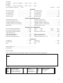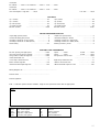
1
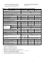
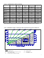
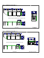
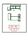
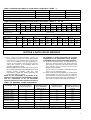
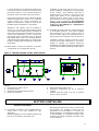
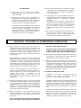
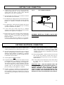
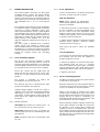
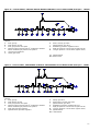
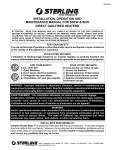
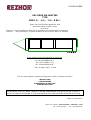
0310DF00GBEN GAS FIRED AIR HEATERS TYPE DFMA 5/.. - 10/.. - 18/.. & BC/.. Direct Gas fired flue-less appliances with automatic electric burner control for use as : Type A2 : flue-less appliances with the air circulating fan downstream of the burner Type BC/.. : are gas burners & controls modules for use in ducts and/or air handlers These appliances meet the following EC Directives : Dir. CE 90/396/EEG G.A.D. Dir. CE 89/336/EEG E.M.C. Dir. CE 73/23/EEG L.V.D. Dir. CE 89/392/EEG M.D.* * does not apply to BC/.. models This document applies to appliances designed for indoor or outdoor installation INSTALLATION COMMISSIONING MAINTENANCE & SERVICING USER INSTRUCTIONS PLEASE READ THIS DOCUMENT CAREFULLY BEFORE COMMENCING THE INSTALLATION & LEAVE IT WITH THE USER OR ATTACHED TO THE APPLIANCE OR GAS SERVICE METER AFTER INSTALLATION Subject to modifications Reznor U.K. limited – Park Farm Road – Folkestone – Kent Tel : 01303-259141 - Fax : 01303-850002 1. 2. 3. 4. 5. 6. 7. 8. 9. 10 11 12 13 14 15 N.B. INDEX Page Principle of use and operation................................................................................................................2 General...............................................................................................................................................3 Technical data .....................................................................................................................................3 Data for BC modules ............................................................................................................................8 Installing ...........................................................................................................................................10 Air supply requirements ......................................................................................................................11 Gas connection..................................................................................................................................12 Electrical connection ..........................................................................................................................12 Commissioning ..................................................................................................................................13 Maintenance & Servicing ....................................................................................................................17 Fault finding ......................................................................................................................................19 Short parts listing ..............................................................................................................................20 Health and Safety information .............................................................................................................21 User instructions................................................................................................................................22 Annex 1 Test reports .........................................................................................................................24 If optional equipment is supplied with this appliance please refer to the additional instructions supplied with the option. SECTION 1 PRINCIPLE OF USE & OPERATION 1.1 1.2 Direct Gas fired Air Heaters are primarily designed for use as make-up air appliances. Gas is injected into a special burner that is fitted within the air stream of an air handling appliance. A proportion of the air flowing through the appliance is entrained into the burner to provide a combustible air/gas mixture. Reznor DFMA series appliances are designed for use as permanent ventilation appliances. 6. 7. 8. As the products of combustion are discharged directly into the space to be heated it is essential that the rules of application as outlined in this document are observed. Reznor DFMA air heaters are designed and manufactured to comply fully with the requirements that ensure complete safety in use is assured provided the installation is carried out as outlined in this document. Reznor Direct Gas Fired Air Heaters operate on the "pull through" principle i.e. the burner being located on the negative pressure side of the air circulating fan. This method ensures that a homogenous air stream is discharged from the appliance. Figure 1. Legend 1. 2. 3. 4. 5. 1.3 1.4 A typical Reznor Direct Gas Fired appliance is described in figure 1. TYPICAL DIRECT GAS FIRED AIR HEATER LAY OUT figure 1: Air circulating fan Discharge air temperature sensor Fan motor and drive assembly Overheat limit air temperature duct thermostat Minimum air discharge temp. duct stat with timer (opt. 6.08) Wiring and controls compartment Airflow proving differential control Gas controls 0401DF00GBEN 9. 10. 11. 12. 13. 14. 15. 2 Dirty filter control (option 5.11) Maximum air inlet temperature duct stat (option 6.03) Air dampers (optional) Weather proof fresh air intake hood (optional) Air filter section (optional for DFMA 5 & 10) Air filters (optional) Airstream burner 2 SECTION 2 GENERAL IMPORTANT NOTICE: Reznor Direct Fired Air Heaters are constructed to meet unique specifications for which they are ordered. When tested before leaving our factory they are adjusted, fixed and sealed in their appropriate settings. Further adjustments that may be found necessary to be carried out by the installer/commissioning engineer must respect the criteria for such apparatus and the engineer responsible for carrying out any adjustment assumes responsibility for the continued safe operation of the appliance when it taken into service. Sealing of a reset device must be applied. Read the unique appliance wiring diagram, data plate and test report in conjunction with this document. 2.1 Before installation, check that the appliance as described on the packaging label is in accordance with the correct type and model as specified on the data plate and complies with your customer order. 2.2 Leave the appliance fastened to transit packing until it is ready to be sited. This affords protection to the cabinet and its framework as well as providing base clearance for trucking etc. 2.3 Please read this document commencing installation. 2.4 These instructions are only valid for the country of use indicated on the appliance i.e.: GB - IE. If these symbols are not shown, it is necessary to obtain appropriate technical instructions which will provide information concerning the necessary modification of the appliance for the conditions of use in the country concerned. Such instructions may be obtained upon request from your supplier. 2.5 2.6 before Check that the local distribution conditions of electricity supply, type of gas and pressure, and adjustment of the appliance are compatible. Convection Air Heaters for Commercial and Industrial Space Heating". The Installation must also be in accordance with the relevant requirements of "The Gas Safety (Installation and Use regulations) and (Amendment Regulations 1990)" and The "Building" and "Electrical Regulations" (in GB the IEE Regulations). The requirements of the "Local Building Standards Office", the premises "Insurance" undertaking and the"Fire Office" must also be observed. 2.7 Special attention to the air supply and ventilation requirements contained in section 5 of this document must be given to prevent environmental conditions occurring that may be detrimental or even dangerous to health. 2.8 Unauthorized modification of this appliance or departure from use in the manner for which it was intended by the manufacturer or installation in a manner contrary to these instructions, may constitute a hazard and jeopardize all warranties. Deviations should only be carried out after formal consent has been obtained from the manufacturer. 2.9 Ensure the environment in which the air heater will be installed will not create a hazard i.e. where excessive (volatile) dust, flammable or corrosive substances and/or vapours and combustible materials may be present. When installed in Great Britain the total installation must comply with the requirements and recommendations of British Standard BS 6230 1991. "Installation of Gas Fired Forced SECTION 3. TECHNICAL DATA 3.1 3.2 The Reznor DFMA series air heaters are manufactured in 3 basic model sizes: DFMA 5/.., DFMA 10/.. and DFMA 18/.. The BC/.. types are complete burner and control modules which are intended to be used in conjunction with ducted air distribution systems or air handlers supplied by others. The heat input is based upon the requirement for raising the air volume at a reference inlet air temperature to the design output temperature, Tables 1 and 2 indicate the duties available. Due to the variety of applications for which DFMA air heaters can be used specific data for each model is described in quotations, order acknowledgements and on appliance data plates.. 3.3 DFMA air heaters may under special circumstances be used with recirculated air from the space being heated. When used in this manner assuming they will be dual-use appliances i.e. re-heating/make-up air heaters then outlet air volumes will vary due to the difference in the inlet air temperature which will have been designed to meet the lower outdoor air criteria. Where re-circulation of the already heated air is practised then additional external controls 3 concentrations in the heated space will not be exceeded providing the air volume figures stated are met. to monitor the air quality within the heated space may be required. Refer to tables 1.2 and 5 for data of how to assess the criteria necessary to ensure carbon dioxide (CO2) Table 1.1 DFMA APPLIANCE DATA STANDARD SPECIFICATION MODELS DFMA MODEL SIZE DFMA - 5/.. Gas category 'Cat.' DFMA - 10/.. DFMA - 18/.. II2H3+ Air supply/ combustion products evacuation type A2 SINGLE STAGE ON/OFF BURNERS Heat input range (Hs) 'Qn' kW 74,0 - 148 74,0 - 296 74 - 493 Heat input range (Hi) 'Qn' kW 67,5 - 135 67,5 - 269 67,5 - 444 High heat output range kW 67,5 - 135 67,5 - 269 67,5 - 444 MODULATING HIGH/LOW BURNERS Heat input range (Hs) 'Qn' 1 kW 3,7 - 148 3,7 - 296 3,7 - 493 Heat input range (Hs) 'Qn' 1 kW 3,4 - 135 3,4 - 269 3,4 - 444 kW 3,4 - 135 3,4 - 269 3,4 - 444 Heat output range 1 Gas supply pressure 'P'2 natural gas mbar (GB) =17,5 (IE) = 20,0 propane mbar 37,0 butane mbar 28,0 Gas service connection (not supply line size) Temperature rise <T range to maximum Air volume3 External static pressure range Rc : Rc 1 Rc 12 K 2 - 55 2 - 55 2 - 55 m3/h 5000 - 9000 10 000 - 18 000 15 000 - 30 000 Pa Electrical supply 230/240 V 1 N ~ 50 Hz 380/415 V 3 N - 50 Hz Protection grade Indoor air heaters IP20, Outdoor air heaters IP45 kW 0,75 - 3,0 1,1 - 7,5 2,2 - 11,0 Total electric rating 4controls load kW 0,11 0,15 0,23 " kg 182 306 488 " kg 200 320 500 5 Appliance weight gross (shipping) 2 3 4 5 380/415 V 3 N - 50 Hz Fan motor rating Appliance weight net 1. 50 - 300 5 Burners are assembled from modular sections of imperial length six inches (6", 0,5 feet). Each section has a maximum heat input of 74,0 kW on gross calorific value: DFMA 5/.. in 0,5 modules to 1,5 feet long DFMA 10/.. in 0,5 modules to 2,5 feet long; DFMA 18/.. in 0,5 modules to 4,0 feet long. NOTE: The second part of the number /.. is the ? T EK as specified. Maximum gas pressure at inlet to appliance = 50,0 mbar Natural gas G 20, calorific heating value 10,48 kWh/m3 on Hs @ 15 EC & 1013 mbar Propane G 31, calorific heating value 14,0 kWh/kg. Butane G 30, calorific heating value 13,7 kWh/kg Total electrical rating equals motor load rating plus controls load Approximate dependant on motor size burner length and options fitted 4 Table 1.2 : RANGE RATING OF DFMA AIR HEATERS BURNER LENGTH Q = ft MAXIMUM HEAT INPUT kW @ GCV MINIMUM HEAT INPUT kW @ GCV 1 MINIMUM AIR VOLUME per kW HEAT INPUT m3/h DFMA MAXIMUM AIRFLOW m3/h DFMA 5.. 0,5 74 3,7 60,8 9 000 DFMA 5.. 1,0 or 1,5 148 7,4 60,8 9 000 DFMA 10.. 0,5 74 3,7 60,8 18 000 DFMA 10.. 1,0 148 7,4 60,8 18 000 DFMA 10.. 1,5 222 11,1 60,8 18 000 DFMA 10.. 2,0 or 2,5 296 14,8 60,8 18 000 DFMA 18.. 0,5 74 3,7 60,8 30 000 DFMA 18.. 1,0 148 7,4 60,8 30 000 DFMA 18.. 1,5 222 11,1 60,8 30 000 DFMA 18.. 2,0 296 14,8 60,8 30 000 DFMA 18.. 2,5 370 18,5 60,8 30 000 DFMA 18.. 3,0 444 22,2 60,8 30 000 DFMA 18.. 3,5 or 4,0 518 25,9 60,8 30 000 MODEL TYPE NOTE: 1 Necessary to limit the volume of carbon dioxide (CO2) that enters the building as a result of combustion. Table 2 : PERFORMANCE GRAPH - TEMPERATURE RISE RE MAXIMUM AIR VOLUME for MODEL SIZE Legend : <T = Temperature rise GCV = Gross calorific value of the gas (e.g. wet) P = Heat output in Watts Cp = Specific heat of air taken as 0.3423 W = Power in Watts V = Air volume K = Temperature Kelvin 5 Figure 2 : DIMENSIONS MODEL DFMA - 5 SIDE ELEVATION STANDARD HAND CONTROLS SIDE PLAN VIEW END VIEW AIR OUTLET Figure 3 : DIMENSIONS MODEL DFMA - 10 SIDE ELEVATION STANDARD HAND CONTROLS SIDE PLAN VIEW END VIEW AIR OUTLET 6 Figure 4 : DIMENSIONS MODEL DFMA - 18 SIDE ELEVATION STANDARD HAND CONTROLS SIDE PLAN VIEW END VIEW AIR OUTLET 7 Table 3. Maximum load ratings for 4 pole motors: Single phase - DFMA - 5 Motor rating kW Phase ~ 1 1 Voltage V 230 230 ~A 4,0 4.7 Load rating " 5% 0,55 0,75 Starting mode Direct on line Table 4. Maximum load ratings for 4 pole motors: Three phase - DFMA - 5 - 10 - 18 Motor rating kW 0,55 0,75 1,1 Phase ~ 3 3 3 3 3 3 3 3 3 3 3 3 Voltage V 230 400 230 400 230 400 230 400 230 400 230 400 Load rating " 5% A 2,4 1,4 3,1 1,8 4,5 2,6 5,0 2,9 8,3 4,8 11,5 6,6 Starting mode 1,5 2,2 3,0 Direct on line Table 4. concluded Motor rating kW 4,0 Phase ~ 3 3 3 Voltage V 230 400 230 400 230 400 230 400 230 400 15,3 8,8 20 11,5 26,9 15,5 36,5 21,0 50,4 29,0 Load rating " 5% Starting mode A 5,5 7,5 3 3 11,0 3 3 15,0 3 3 3 L/Y SECTION 4 DATA FOR BC MODULES 4.1 BC../.. Direct Gas Fired Modules comprise air stream burners mounted in a profile plate (panel) connected to a gas manifold and controls train. They are for installing as A2 type appliances i.e. burner on the negative pressure side of the fan within duct systems or for installing within air handlers supplied by others. When installing these modules it is necessary that the completed installation including the direct fired heating module complies with the total requirements of PrEN 525 1996 (scheduled to be published as EN 525../1996). NOTE: It is the responsibility of the installer of BC modules to ensure that the total installation complies with the requirements of Dir CE 89/392/EEC Machinery Directive and that components included in the installation i.e. motors, thermostats, etc. meet the requirements of CE 89/336/EEC Electro Magnetic Compatibility and CE 73/23 Low Voltage Directives. 4.2 BC Direct Gas Fired modules are designated by the letters BC (burner/control) with digits following indicating the maximum heat input rating in kW gross calorific value of the gas and the burner length (in feet imperial). e.g. BC 148/1,0 is a module of 148 kW heat input from 1 foot of airstream burner. 4.3 Table 5 indicates the possibilities for modules with burner lengths from 0,5 to 4,0 feet. It should be noted that this is not the maximum size that can be manufactured. For larger sizes extrapolation of the criteria contained in the table is necessary. Table 5. BC MODULES possible configurations BC MODEL TYPE MAXIMUM HEAT INPUT kW @ GCV1 BURNER LENGTH FEET IMPERIAL Dim "X" fig. 5 MINIMUM HEAT INPUT kW GCV MINIMUM AIRFLOW per kW HEAT INPUT per m3/h DFMA BC 25/0,16 25 0,16 1,23 60,8 DFMA BC 74/0,5 74 0,5 3,7 60,8 DFMA BC 148/1,0 148 1,0 7,4 60,8 DFMA BC 222/1,5 222 1,5 11,1 60,8 DFMA BC 296/2,0 296 2,0 14,8 60,8 DFMA BC 370/2,5 370 2,5 18,5 60,8 DFMA BC 444/3,0 444 3,0 22,2 60,8 DFMA BC 518/3,5 518 3,5 25,9 60,8 DFMA BC 592/4,0 592 4,0 29,6 60,8 1 Necessary to limit the volume of carbon dioxide (CO2) that enters the building as a result of combustion 8 4.4 Profile openings for burners must be designed to provide an airstream velocity across the burner of 15m/s. When calculating the area for the profile opening a distance of 50 mm must be allowed at either end of the burner. 4.6 Profile opening must be sized in accordance with the criteria stated below. It is usual to add 50 mm to the resultant height of the profile to allow for adjustment of the air velocity across the burner when the system is commissioned. 4.5 The design temperature rise of the air must not exceed 55 EK. 4.7 Refer to figures 5 and 13 for profile design. CALCULATING BURNER PROFILE OPENINGS Example Instruction 1. 2. Assumed burner length = 3,0 ft Calculate total burner area: Overall length "X" of burner x burner area per foot (area per foot = 0,65 ft2) "X" as figure 5 3,0 ft X 0,65 ft = 1,95 ft2 Convert to m2 = X 0,0929 1,95 ft2 X 0,0929 = 0,181 m2 Calculate the net profile area: 30 000 m3/h ) 3 600 = 8,333 m3/s Total air volume m3 /s Required air velocity Vo 3. 8,333 m3 /s = 0,555 m2 15 m3 /s NOTE: Use constant Vo 15 m/s Calculate the gross profile area: Burner area + net profile area combined 0,181 m2 + 0,555 m2 = 0,736 m2 4. Calculate the length of the profile opening: Burner length "X" + 50 mm each end 5. Calculate the height of the profile: 3,0 feet = " 914 mm 914 mm + 100 mm = 1014 mm (1,014 m) 0,736 m2 = 0,726 m =726mm+ 50mm =776mm 1,014 m Gross profile area Y= Length "Y" as figure 5 Add 50mm for profile adjustment when commissioning _______________________________________________________ 4.7 Figure 5 shows a typical duct or air handler section. The dimensions A, B & C are those of the client specification, it should be remembered that these dimensions must allow for the burner installation sizes calculated as indicated above. When the direct fired heating module manufactured it will be set and sealed in is accordance with the criteria specified by the client. Refer to the instructions for the Reznor DFMA series air heaters contained in this document for adjustments etc. The areas in which the burners are installed, must remain free from any obstructions i.e fans, dampers,filters,etc. 9 ventilated at both high and low level so as to prevent a build-up of unburnt gas and overheating of the controls. Such openings shall have a minimum area of at least 2% of the area of the largest plain surface of the compartment. The openings shall be sized so that a of the area is open at the top of the compartment and b at the bottom of the compartment. All compartment openings must not must not allow the insertion of a ball of 16 mm diameter i.e. constructed to conform with IP 20 If closure dampers are incorporated within the air circuit they must be electrically interfaced with the burner controls so as to prevent start-up of the burner when not in their fully open position. If discharge air outlet louvres are fitted, the blades shall be provided with a stop, so as to prevent closure beyond 45E. Closure positioning for appliance transportation purposes shall not be possible whilst the appliance is operational. Appliances and systems that are installed in excess of 1,8 m above floor level and those that are intended to be installed outdoors shall have all removable panels that are intended to be used for service and maintenance access, secured by permanently fitted restraining straps to prevent their falling when used. It is recommended that substantial earth bonding straps are used for this purpose. Hinged panels are deemed to satisfy this requirement. 4.9 For DFMA air heaters and duct systems designed to be installed outdoors, all air inlets including those mentioned in 4.7 above must be sited so that the lowest edge of the opening will be at least 500 mm above the level of any deck or floor. Ventilation openings shall be protected so that they will not become obstructed e.g. by leaves, storage of material, etc. Notices should be provided by the installer and posted as appropriate to ensure that ventilation openings remain clear at all times. 4.8 When burner controls are installed in a separate compartment, the compartment must be Figure 5 : DESIGN CRITERIA FOR BC APPLICATIONS Legend : 1. Inlet protection grille to IP 20 2. Airstream burner 3. Adjustable and sealable burner profile 4. Burner gas manifold 5. 6. 7. Burner inspection viewing port Separated compartment for gas & electrical controls Optional protection grille to IP 20 to prevent access in front of burner SECTION 5 INSTALLING OUTDOOR APPLIANCES: 5.1 If the DFMA air heater is to be installed outdoors ensure that it has been supplied for this application. When the appliance is to be installed outdoors and the site is accessible to the public then appropriate protection in the form of a fence must be provided. The premises security may be jeopardized by the installation of outdoor air heating appliances. Consideration should be given to the possibility of un-authorised entry to the premises being made via appliance and duct work access panels etc. 10 ALL APPLIANCES 5.2 Check that the air supply and ventilation requirements will be met as outlined in section 6 of this document. 5.3 The DFMA air heater may be installed in a suspended manner using the suspension points provided on the appliance. These air heaters may be base mounted. Ensure that the air heater is secured to any base mounting arrangement. Ensure that the structural elements of the building are adequate to carry the weight of the appliance and its ancillary components i.e. the air distribution duct work. If suspended the appliance should remain rigid so as not to impose a strain on the services connected to the appliance. 5.4 Ensure that sufficient space around the air heater is maintained for servicing and that the appliance is not sited where it may suffer from damage by, e.g. fork lift trucks. 5.5 The appliance and its air distribution duct work should be insulated and protected by a waterproof membrane where it is exposed to outdoor conditions. Duct work should be designed so that minimum restriction at the air outlet (and if applicable the air inlet) on the appliance exists. It is important that an even airflow through the air heater is maintained to ensure good combustion takes place. 5.6 Air inlets to the building must be protected so as to prevent the ingress of birds, leaves, etc. Warning notices should be displayed advising about blocking air inlets to the air heaters. SECTION 6 AIR SUPPLY for COMBUSTION & VENTILATION 6.1 Reznor DFMA air heaters mix the products of combustion with fresh air entering the appliance and discharge the mixture directly into the space to be heated. To maintain a safe and healthy environment it is therefore, essential that sufficient fresh air is provided in accordance with the amounts advised in this document. Normally DFMA air heaters are used for make-up air purposes the extract volume of the air being matched by the inlet air volume of the air heater. Recirculation of heated air may be practised provided that the appropriate volume of fresh air to ensure a safe level of CO2 is maintained. The air supply requirement can be calculated from the data provided in this section. Power air extract equipment i.e. spray booths, etc. must be electrically interlocked with the air heater. If varying proportions of fresh air/recirculated air are possible by control of dampers in the heating/ventilating system these must also be interlocked to ensure that an unsafe condition cannot be achieved. 6.2 Unless specified to the contrary by users or relevant authorities, the allowable limits of carbon dioxide (CO2) in the atmosphere as result of direct gas fired are heating must not exceed 0,28% (V/V) or 2800 ppm / (2800/10-6). This figure when met ensures that the other gases contained in the products of combustion are maintained within safe limits. 6.3 Where recirculation of air is practised it should be limited in proportion to the total air volume passing through the appliance and entrained downstream of the burner. limit the CO2 limit indicated in table 5. The figure of 60,8 m3 of fresh air per KW of heat input at gross calorific value must be maintained as a minimum requirement for all Reznor DFMA air heaters. 6.4 In the event that the design dictates deviation from the requirements of clause 6.3 above. Reznor engineering department must be consulted for approval. 6.5 Reznor recommend that in cases where recirculation is required then only recirculation air volumes in excess of the volumes required as stated in clause 6.3 may be considered. If recirculation is practised that zones where warm air is discharged are provided with CO2 constant monitoring devices electrically interfaced with the appliance burner safety controls. 6.6 Ventilation including BC Models: Ventilation of the burner compartment must be provided by the inclusion of openings sized in accordance with mandatory requirements. For DFMA air heaters and duct systems designed to be installed outdoors, all air inlets including those for ventilation of the burner controls compartment above must be sited so that the lowest edge of the opening will be at least 500 mm above the level of any deck or floor. Ventilation openings shall be protected so that they will not become obstructed e.g. by leaves, storage of material, etc. Notices should be provided by the installer and posted as appropriate to ensure that ventilation openings remain clear at all times. On no account should the volume of recirculation air reduce the volume of fresh air below that required to 11 SECTION 7 GAS CONNECTION 7.1 Connection to a gas service may only be carried by suitably qualified persons. The gas installation must comply with the rules in force using materials appropriate for gas service installations. Fig. 6 GAS CONNECTION DETAIL 7.2 Check that the gas category is in accordance with the data described on the air heater. 7.3 An adequate gas supply sized to provide the dynamic pressure for the volume required by the direct fired air heater(s) is essential to maintain the nominal heat input. 7.4 For applications where pressures higher than those normally supplied for the appropriate gas a reducing governor is available as an option. 7.5 A 90E action gas service tap and, to facilitate servicing, a disconnect union fitting must be provided adjacent to the appliance, see figure 6. 7.6 Ensure that a gas service includes a filter and has been tested and purged in accordance with prescribed practice prior to commissioning and taking the air heater into service. If there is doubt about the adequacy of a gas filter, one should be fitted at the gas inlet to the appliance. WARNING: NEVER use a FLAME to test for GAS Soundness !!! SECTION 8 ELECTRICAL CONNECTION 8.1 The Electrical installation may only be carried out by suitably qualified persons observing the rules in force. 8.2 Check that the electrical specification is in accordance with the specified data on the air heater. A unique appliance wiring diagram is supplied as a separate document attached to this one, plus an additional copy is attached to the air heater. 8.3 These appliances must be earthed. 8.4 A separate electrical isolator for each heater must be provided adjacent to the appliance in a position so that it is visible to any person working on the appliance. The isolator must have a contact separation of at least 3.0 mm on all poles. The isolator must be of the key operable type so that electrical safety for those persons working on the appliance is assured. 8.5 Ancillary controls are required to provide timed heat cycles, if appropriate, room comfort temperature level, frost protection, override air circulation etc. These are not included with the appliance and should be ordered separately. 8.6 Reznor direct fired air heaters are supplied equipped with a fuse included for protection of the heater burner controls circuit. it is the responsibility of the installer to provide fuses as appropriate for external control/s circuits. 8.7 When planning DFMA controls circuits be sure to take into account any interface circuits that may be required between the gas burner and e.g. air dampers, extract fans,etc. 8.8 For BC models ensure that motors and controls fitted by others meet the requirements of 4.1 of this document. IMPORTANT NOTE: DFMA AIR HEATERS THAT ARE APPLIED AS CONTINUOUS OPERATING APPLIANCES, i.e. 24 HOURS EACH DAY MUST HAVE A DEVICE (TIME SWITCH) INCLUDED IN THE EXTERNAL CONTROL SYSTEM TO SWITCH OFF THE APPLIANCE BRIEFLY ONCE EVERY 24 HOURS. THIS IS NECESSARY TO TEST THE INTEGRITY OF THE AIR FLOW PROVING SAFETY DEVICE. 12 SECTION 9 COMMISSIONING,LIGHTING AND OPERATION COMMISSIONING 9.1 Normally Reznor Direct Fired air heaters do not require commissioning. Final testing after production ensures that: If installation has been carried out strictly in accordance with this document and air circulation ducting etc. has been sized correctly so that the system design parameters are met, the appliance is ready to be taken into service. 9.2 Checks to ensure; - earth continuity - resistance to earth - phase supply to correct terminals - current rating and fuse value - correct supply gas pressure - correct burner gas pressure - satisfactory & smooth ignition - that fans rotate in the correct direction - that any air discharge louvres cannot be closed beyond 45E when the air heater has been taken into service 9.3 In addition to the above requirements checks to ensure that the fan performance and motor load factors are correct for the application and in accordance with the appliance data plate. 9.4.2 Adjusting the fan speed can be carried out by altering the diameter of the adjustable drive pulley. - Loosen the belt tension adjustment device and remove the drive belt/s. - Refer to figure 7 and note that the outer section of the drive pulley is secured by a hexagon socket grub screw to a flat on the pulley hub, this is positioned by loosening the grub screw sufficiently to enable the pulley to be either opened or closed by turning it on the thread on which it is engaged. - It should be noted that one complete turn of the pulley half is equal to approximately 8% of the fan speed. Closing the pulley increases the speed and opening decreases the speed. - after making speed adjustments tension belt in accordance with the dimensions given in figure 7 and check pulley alignment to ensure the belt runs correctly. N.B. Always ensure that the pulley is tightened onto a flat of the hub before switching on the fan, even when testing a reset condition. Figure 7 Pulley & belt adjustment Deviations to air flow rate from that which the air heater was originally set will affect the burner performance. if adjustments are necessary note section 9.4 below. 9.4 Drives general and adjustments 9.4.1 Before commencing work on the fan assembly: - Set external controls to off or their lowest setting. - Turn OFF the gas supply to the air heater. - Switch OFF the electricity supply to the air heater. Lock the appliance electrical isolator in the OFF position. - Open the service access panel and if appropriate, remove protection guards and carry out adjustments as required. - Before placing the appliance back into service or switching the fan on ensure that all access panels and if appropriate, protection guards are replaced and secured. N.B. Rotational speed checks should be carried out using an infra red tachometer or stroboscope. After any adjustment change the data described on the appliance test report accompanying this document. 9.5 BURNER PROFILE ADJUSTMENT DFMA air heaters are fitted with profile adjustment plates these will have been set and sealed for the air flow duty specified. 13 In the event that the air flow duty is changed from the design rate when the appliance is commissioned it will be necessary to re-adjust the plates to maintain the necessary design air velocity across the burner, NOTE; THIS IS MOST IMPORTANT. The design velocity at 15 EC 1013,25 mbar must be set to " 15 m/s. If adjustment is made, the new setting position should be marked and sealed and the new dimensions recorded on the test report accompanying this document. 9.6 electronic flame relay will switch off and lockout will occur. This will cause the signal lamp to glow within the reset switch on the appliance and/or a remote control if fitted). After about 10 seconds the reset button on the appliance or the remote control can be operated in order to reset the appliance. 9.7.5 LIGHTING - Ensure that air discharge louvres and/or grilles are set to an open position; Check if fire dampers are fitted in the duct system these are open and secured; Ensure that inlet air dampers if fitted are open and in the correct setting mode; Turn ON the gas supply to the air heater; Switch ON the electricity supply to the air heater; Set appliance controls to an ON setting; If fitted ensure that a time control is at an ON setting; NOTE: The gas burner will only operate when the air circulating fan is running. - If reset button on heater and/or on remote control (if fitted) glows, press reset button. Heater should now light automatically within 2 minutes. For a new installation or if the appliance has been turned off for an extended period then up to 3 attempts to light the air heater may be necessary. If the heater still does not light, consult the fault finding guide section 11. Flame failure protection is by the ionisation principle i.e. the ability of a suitable flame to pass an electrical current between the igniter and the earthed burner assembly. To check the flame current is adequate it is necessary to connect a DC micro ammeter between the flame sensor and it's lead wire connection. Ionisation current should be; " 0,5 µA. of the value stated in the Reznor appliance test report accompanying this document. Note: The circuit carries mains voltage when energised. 9.7.6 In the event of the air volume falling below an adequate or safe level i.e. due to blocked filters, broken fan, etc., safety shut down of the burner and/or burner lock out will occur. Dependant on the control type fitted, resetting of the burner control may be necessary before the appliance can be placed back into service. 9.7.7 If the burner flame is extinguished for any reason during a run cycle safety shut down will take place. Manual intervention to reset may be necessary to put the air heater back into service. 9.7.8 In the event of overheating for any reason, thermally a activated fail safe overheat control operates to switch off the burner. 9.7.9 To switch off the air heater for a short period; a/ switch OFF the appliance control To relight, switch ON the appliance control 9.7 OPERATION 9.7.1 At the dictates of the external controls, an electrical circuit is made and air circulation fan runs. 9.7.2 Provided adequate air flow is proved, the fan alone will run for a pre-purge period to ensure that the appliance and the air distribution system are adequately ventilated. 9.7.3 Refer to figure 8. For prolonged period; a/ switch OFF the appliance control; b/ turn gas supply to the appliance OFF; c/ switch OFF electricity supply to the air heater. To relight follow lighting instructions. 9.7.10 The gas service tap must only be operated in emergencies, for servicing or prolonged periods of shutdown of the air heater. DFMA air heaters light automatically by a spark ignition device which ignites a start gas burner at the dictates of an automatic sequenced electronic burner control. At the end of the pre-purge period the start gas valve(s) will open and the ignition burner will be lit. Provided a satisfactory flame has been established, the main burner will light after an ignition burner proving period. 9.7.4 If the burner has not lit within the proving time, the 14 9.8 9.8.3 BURNER MODULATION Connect a manometer to the burner gas pressure test point, and then proceed as follows; Most Reznor DFMA air heaters are fitted with modulating burner controls. This feature enables the burner to modulate at the dictates of the external controls between the maximum high fire rate and the low pre-set point. The minimum low rate achievable is 20 : 1 or 5 % of the high fire rate. High rate adjustment; NOTE: When carrying out adjustments ensure that the appliance dynamic gas inlet pressure is adequate. The standard system fitted to provide modulation is a "Maxitrol" system. Comprising the components necessary for burner modulation control, duct and/or room temperature sensors, signal amplifier and modulating gas pressure regulator known as type M or MR. The MR gas pressure regulators are powered by a variable 24V DC voltage. Maximum outlet pressure occurs between 15 - 20 V DC (high fire). Minimum outlet pressure occurs at 0 - 5 volts DC. The power signal is obtained from a Maxitrol system A1014 duct sensing or A1044 room sensing amplifier which is an integral control within the appliance or, if preferred a signal from another control system by other than Reznor designed to provide the required sensors and controlling voltages. 1. Disconnect the wires to from terminal 4 on the A 1014 or terminal 3 on the 1044 amplifier or the low fire control circuit (see appropriate wiring diagram). Ensure that between 15 and 20 volts remains on the regulator. This causes the regulator to provide continuous high rate. 2. Adjust pressure regulator to obtain the required manifold burner pressure clockwise rotation increases pressure (see fig. 8). 3.Re-connect the wire to restore the amplified control. Low rate adjustment; 1. Disconnect one wire from the terminal on the M 611 regulator, this will cause the regulator to provide continuous low rate; 9.8.1. M 611 Modulating Regulator The M 611 gas pressure regulator is fitted downstream of any other gas pressure control. It should be noted that adjustment of any upstream pressure regulator will be necessary to compensate for the pressure loss across the M 611 regulator. The M 611 controls the gas supply when the safety and main gas valves are open. At zero volts the M 611 is in the normally low pre-set by-pass position. 2. Remove cap (figure 8, A) and loosen the screw, turn adjusting screw (B) (use a c" hexagon wrench) to desired low rate setting, (clockwise reduces minimum flow rate) NOTE: there are two adjustment positions either side of the regulator; 3. Replace control wire. 9.8.4 MR 212 Modulating Regulator the The MR 212 regulator operates in a similar manner to the M 611, (see figure 9). The maximum gas rate is controlled by the main gas pressure regulator (see figure 8). When the main burner gas valves open the MR 212 controls the gas flow to the main burner. The MR 212 is in a normally low set point position. The by-pass is adjustable for setting low/minimum gas rate (see figure 8). Variable voltage applied to the M 611 causes a magnetic core to move thus actuating a diaphragm allowing gas to flow at a controlled rate to the main burner. At the maximum control voltage the burner will be at it's highest set rate (high fire of the burner). 9.8.2 M 611 Adjustments: Extreme situations; LOW RATE: When there is no voltage to the 611 gas flow will only be via the by-pass; M HIGH RATE: When the M 611 is powered the maximum gas flow rate is controlled by the main gas regulator. When no gas pressure is present in the upper chamber above a diaphragm a spring closes down the gas regulator into the pre-set low position via a by-pass the rate of which is controlled by an adjustable in-built separate pressure regulator. This is the minimum or low rate condition. When modulating voltage is applied, gas pressure in the upper chamber of the MR 212 overcomes the pressure of the closing spring causing the regulator to open in a controlled manner. The more the modulator opens the greater the pressure in the upper chamber thus the higher the gas flow rate. The high gas rate is controlled by the integral main gas pressure regulator. NOTE: Actuation of the core occurs between 5 and 15 volts. 15 9.8.5 Extreme situations: Low fire gas rate is controlled by the by-pass setting; 2. Remove cap, loosen the screw (C) and turn adjusting screw (D) to required low rate setting,(clockwise rotation reduces the low rate) High fire gas rate is controlled by the voltage applied to the MR 212 up to the maximum set point which is dictated by the integral main gas pressure regulator. 3. Tighten screw (C), replace control wire. MR 212 Adjustments: Connect a manometer to the burner gas pressure test point, and then proceed as follows; NOTE: When carrying out adjustments ensure that the appliance dynamic gas inlet pressure is adequate. High rate adjustment; 1. Disconnect the wires to terminal 4 on the A 1014 amplifier or terminal 3 on the A 1044 amplifier, or remove the low fire amplified current circuit, (see appropriate wiring diagram). Ensure that between 15 and 20 V remains on the regulator. This causes the regulator to provide continuous high rate; 2. Remove the sealing cap (figure 9 key A) and turn the regulator adjusting screw to obtain the required manifold burner pressure. Clockwise rotation increases pressure; 3. Re-connect the wire to restore the amplified current. Low rate adjustment; 1. Disconnect wire from the terminal on the MR 212 gas regulator, this will cause the regulator to provide continuous low rate; 9.9 DFMA BURNER PRESSURES The operating burner pressure of type A DFMA air heaters is influenced by the negative static pressure of the air passing through the appliance, this negative pressure causes a vacuum on the gas manifold which is open to the airstream via the burner gas ports. The heat input is therefore, the pressure recorded on the gauge whilst the air circulating fan is running at it's pre-set condition. This reading is the total gas pressure and is the sum of the negative gas pressure and the positive gas pressure to meet the required pressure setting i.e. for high rate. When in low rate setting the gas manifold pressure will read negative. To check the burner pressure setting: 1. Loosen the test points screws and then connect a manometer to both the air stream reference and burner manifold test points. Read off the pressure which is the total burner pressure. 2. When test is complete, remove manometer and close securely screws on test points. IMPORTANT When commissioning is complete ensure that the commissioning report, annex 1, pages 25 & 26 of this document this and supplied with the air heater is completed in accordance with the instructions described thereon. Figure 8 : M 611 Modulating Gas Pressure Regulator HIGH RATE ADJUSTMENT 9 16 Figure 9 : MR 212 Modulating Gas Pressure Regulator Legend: 1. High rate main burner adjustment 2. Low rate adjustment SECTION 10 MAINTENANCE & SERVICING 10.1 General : Servicing and maintenance work may only be carried out by appropriately qualified persons. 10.2 Caution: Inadvertent substitution or replacement of components similar to those specified or replacement in a manner contrary to the method described in this document could constitute a hazard. 10.3 Before commencing service work: Switch OFF the air heaters at the external controls, WAIT until the appliance fan has stopped and then; Lock OFF (see section 8) the electricity supply to the air heater at the isolator provided; Turn OFF the gas supply to the air heater at the appliance isolation tap provided. 10.4 Generally clean the appliance thoroughly whilst checking the items listed below. 10.5 Features to check when carrying out service: 1) Security of appliance installation including; suspension devices; ductwork; gas service; electrical installation including external controls; 2) Air heater cabinet; check for damage, check access panels and ensue that fastening devices are operable, check for air leakage around duct work joints, check condition of damper blades if fitted. 3) Air handler: Check security of drive pulleys, check drive belts, ensure that fan bearings are clean and look for signs of wear by checking end float on blower shaft/s, check fastening of motor and condition of electrical connections to it including contactor and overload if applicable. 4) Air dampers: If dampers are fitted check their operation and that linkages are secure and that travel of the dampers is complete in respect of their purpose. 5) Gas burner: Inspect gas burner and look for signs of corrosion and distortion that may indicate over firing or incorrect air flow across the burner. Check the condition of the ignition and sensor electrodes and their wire connections, look for signs of damaged ceramic insulators. Check gas outlet ports on both the ignition burner and the min burner, clean ports with a soft brush and an air line. 6) The correct location of the adjustable burner profile plates is marked on the appliance during commissioning, ensure that the adjustment position is correct and that the plates are securely set and sealed in the appropriate position. 7) Burner controls, valves, pressure regulators, etc. Check for gas leaks, faulty wire connections and general condition of the components. 10.6 Supplementary controls: Airflow proving switches, automatic burner control, thermal overheat devices, air temperature thermostats, electrical wiring, etc.: Inspect to determine operation, settings, and condition of these devices. 10.7 Upon completion of service work re-commission the appliance in accordance with section 9 of this document. Report any anomalies to the occupier or their representative. 17 Figure 10 : TYPICAL DIRECT FIRED AIR HEATER BURNER CONTROLS M 611 MODULATION (heat input < 180kW) Legend : A. Inlet gas tap B. Main burner gas tap C. Inlet gas pressure test point D. Reference pressure test point P1 combustion chamber Burner manifold gas pressure test point P2 E. Gas pressure regulator G. Safety gas valve H. I. K. L. M. Main (control) gas valve Ignition burner gas valve Modulating pressure regulator M 611 High gas pressure cut-off switch (option 6.34) Low gas pressure cut-off switch (option 6.33) I.B. Ignition burner M.B. Main burner Figure 11 : TYPICAL DIRECT FIRED BURNER CONTROLS ARRANGEMENT MR 212 MODULATION (heat input > 180kW) Legend A. Inlet gas tap B. Main burner gas tap C. Inlet gas pressure test point D. Reference pressure test point P1 combustion chamber Burner manifold gas pressure test point P2 E. Main gas pressure regulator F Ignition burner pressure regulator G. Safety gas valve H. Main burner (control) gas valve I. Ignition burner gas valve K. Modulating pressure regulator MR 212 L. High gas pressure cut-off switch (option 6.34) M. Low gas pressure cut-off switch (option 6.33) I.B. Ignition burner M.B. Main burner 18 Figure 12. Ignition burner detail Figure 13. Burner Profile Adjustment SECTION 11 FAULT FINDING 11.1 Air heater will not start; - Read the commissioning instructions "How it works"; Ensure that the electricity supply is switched ON; Ensure that the gas supply to the appliance is turned ON; Check that all external controls are set in an appliance on mode; NOTE: The burner will not operate unless the air circulation fan is running! - Check fan motor is not locked out on overload; Interface with other air handling apparatus i.e. air extraction fans or their control circuits faulty, Check if appropriate. 11.2 Air circulation fan running burner will not fire: - - Ensure that the inlet gas pressure to the appliance is not too low Burner controls in lock-out mode, Reset; Thermal over-heat (limit) control in lock-out mode, Reset; Low air flow , blocked filter , wrong fan speed, Check; Air flow proving switch broken, set incorrectly, faulty wiring connection, Check; Faulty automatic burner control, Check; - DFMAs over 180 kW heat input: Valves with proof of closure device: Not switched; Faulty ignition burner gas valve or electrical connection to the valve, Check; NO SPARK !!: Faulty ignition transformer or ignition lead connection, ignition current short circuiting ! break in ignition lead; Controls electrical circuit fault, Check circuit in logical manner, against appliance wiring diagram. 11.3 Ignition burner lights and goes out main burner will not light; - 11.4 Insufficient ionisation current, See section 9.7.5 Valves with proof of closure devices: Valve not proven in closed position; Burner lights high or low rate not achieved: - See section 9.3.3 & 9.3.4; 19 SECTION 12 SPARE PARTS LISTING ALWAYS QUOTE APPLIANCE MODEL & SERIAL NUMBER AND GAS TYPE FOR SPARE PARTS 12.1 Gas components DESCRIPTION PART NE MAKERS REFERENCE APPLICATION Air stream burner 6" 50 60200 005L01 "Midco" 60,8 kW DFMA 5 Air stream burner 12" 50 60200 010L01 "Midco" 121,6 kW DFMA 5 or 10 Air stream burner 18" 50 60200 015L01 "Midco" 182,4 kW DFMA 5 or 10 Air stream burner 24" 50 60200 020L01 "Midco" 243,2 kW DFMA 10 or 18 Air stream burner 30" 50 60200 025L01 "Midco" 304,0 kW DFMA 10 or 18 Air stream burner 36" 50 60200 030L01 "Midco" 364,8 kW DFMA 18 Air stream burner 42" 50 60200 035L01 "Midco" 425,6 kW DFMA 18 Air stream burner 48" 50 60200 040L01 "Midco" 486,4 kW DFMA 18 Main gas valve 30 60779 240 ¾”BSP VE 4020A 1021 DFMA 5 Main gas valve 30 60775 240 1” BSP VE 4025A 1020 DFMA 10 Main gas valve 30 60776 240 1 1/2”BSP VE 4040A 1029 DFMA 18 Main gas valve 30 60778 240 2" BSP VE 4050A 1028 DFMA BC Ignition burner gas valve 03 25169 240 1/4" BSP valve Scem All Main gas governor 03 25102 Max. RV 52 3/4" BSP DFMA 5 Main gas governor 03 25103 Max. RV 53 1" BSP DFMA 10 Main gas governor 03 25105 Max. RV 81 1 1/2" BSP DFMA 18 non-modulating Modulating gas regulator 30 60663 Max. M 611 3/4" DFMA 5 modulating Modulating gas regulator 30 60672 Max. M 611 1" DFMA 10 modulating Modulating gas regulator 30 60653 Max. MR 212 12" DFMA 18 modulating Modulating gas regulator 30 60671 max. MR 212 2" DFMA BC Modulating gas regulator 03 25159 1/4" BSP all 12.2 Control components DESCRIPTION PART NE MAKERS REFERENCE APPLICATION Automatic burner control TFI 812 03 25170 10 230 Satronic all Ignition transformer 30 61613, type ZE 23/8,5 Trafo Union all Maxitrol amplifier A 1044 30 60606 A 1044 Maxitrol Maxitrol amplifier A 1014 30 60606 A 1014 Maxitrol Temperature limiter 30 60504 Honeywell 14008E 1040 Differential pressure switch 30 60615 Huba Temperature selector 30 60661 TD114 Maxitrol TD114 (option) Temperature selector 30 60661 TD244 Maxitrol TD244 Duct sensor 30 60668 TS114 Maxitrol TS114 Duct sensor 30 60669 TS244 Maxitrol TS244 Mixing tube 30 60669 112 Maxitrol MT1-12 as per order 20 12.3 Option : Air filters DIMENSION PART NE TYPE QTY USED ON 405 X 510 X 25 (16" X 20" X 1") 60 61041 16x20 EU 4 DFMA 5 = 6 405 X 510 X 25 510 X 510 X 25 (16" X 20" X 1") (20" X 20" X 1") 60 61041 16x20 60 61041 20x20 EU 4 DFMA 10 = 3 DFMA 10 = 6 510 X 635 X 25 405 X 635 X 25 (20" X 25" X 1") (16" X 25" x 1") 60 61041 20x25 60 61041 16x25 EU 4 DFMA 18 = 9 DFMA 18 = 6 SECTION 13 HEALTH AND SAFETY STATEMENT Health and Safety Information for the Installer, Commissioning/Service Engineer and User Under the Consumer Protection Act 1987 and Section 6 of the Health and Safety at Work Act 1974 we hereby provide the following information on substances hazardous to health. Product range reference: " DFMA AIR HEATERS" Reznor DFMA Air Heaters when operating discharge the products of combustion into the space where persons may be present who will inhale the diluted products, this is recognised practice for this type of appliance. You are hereby advised that no unsafe condition will exist provided that the conditions for the installation outlined in this document have been observed. 13.1 During first firing some smoking may occur, this is due to the burning off of protective/lubricating oils used during appliance production. Most of this will have been removed during the production testing process. It is a wise precaution to ensure that adequate ventilation is provided during the initial firing and throughout the commissioning period, this is particularly important if the discharge air is to blow into a confined space. This smoking does not constitute a poison hazard. 13.2 Reznor products contain no asbestos; copper is not employed in gas carrying components; solder which has a melting point below 450EC is not used; paints for corrosion protection and decoration are heat cured and contain no lead. 13.3 The above appliances meet the Electrical Safety requirements of EN60 335 Pt 1 1988. 13.4 Small quantities of adhesives and sealants used in the product are dried and cured and present no known hazard. 13.5 Insulation and Seals. Material: Synthetic Ceramic Fibre with Organic binder. Description: Tapes and Papers Known hazards: Some people can suffer reddening and itching of the skin. Fibre entry into the eyes will cause foreign body irritation. Inhalation will cause irritation to the respiratory tract. As with any dust pre-existing respiratory condition and lung diseases may be aggravated. Precautions: Wear protective gloves when handling. If abrading and dust is generated suitable protective respirators must be used. People with a history of skin complaints may be susceptible to irritation. Dust levels are only likely when the material is abraded. In general normal handling and use for this purpose will not present discomfort. Follow good hygiene practices, wash hands before consuming food or using the toilet. First Aid: Medical attention must be sought following eye contact or prolonged reddening of the skin. 13.6 Thermostat. Material: Illuminating Kerosene. Description: Sealed phial contains a small quantity in liquid form. Recognition: Colourless liquid, paraffin oil/petroleum hydrocarbon odour. Characteristics: Non-corrosive, flammable with no poisonous reference - CH poison Class 3 Precautions: Avoid handling. This product can irritate and defat the skin. Prolonged contact may cause dermatitis. Avoid breathing vapour. Avoid eye contact.Do not ingest. First Aid: Skin. Wash thoroughly with soap and water. Eyes. Rinse immediately with copious amounts of clean water. Ingestion: Seek medical advice. NOTE: If skin irritation persists seek medical advice. Prolonged exposure for the purposes envisaged pertaining to this Reznor product is not anticipated. 21 13.7 Electrolytic Capacitor 1 Phase motors Two types are used by random selection: Recognition: 1.Plastic enclosure 2.Aluminium enclosure Material: Contained liquid electrolyte Known hazards: Electric shock possible if charged. Precautions: Discharge to ground/earth. Do not incinerate. First Aid: Treat for electric shock if affected. SECTION 14. USER INSTRUCTIONS DFMA AIR HEATERS SPECIAL NOTE : The following instructions have been written assuming that the Reznor DFMA air heater is installed as a heating/ventilating appliance. OPERATING How the air heater works: Gas is burned by an airstream burner which fires into a combustion chamber within the appliance air stream. The gas burner is controlled by a double gas valve via an electronic burner control, which is actuated automatically via external controls i.e. a room thermostat and/or a time switch. The burner is ignited by a spark igniter. The burner will not fire until the air circulation fan is running and proved at the appropriate rate. The air circulation fan also provides the combustion air for the burner. Safety: 1. Flame failure is detected by sensor and will immediately cause safe shut down of the burner. 2. Safety against overheating is assured by thermally activated overheat control/s. These control/s require resetting in the event that an overheat situation arises i.e. as a result of blocked air filters, etc. Manual intervention within the appliance is necessary to reset this control device. Resetting of the automatic burner control may also be required. To light the heater: 1. 2. 3. 4. 5. 6. 7. Turn on the gas supply to the air heater. Switch on the electricity supply to the air heater. Ensure time switch (if fitted) is set to a 'ON' cycle. Switch appliance controls to ON. Air heater will light automatically If the appliance does not light: a) check that the burner control does not require resetting. An indicator light glows at the front panel of the appliance and on a remote control if fitted). Reset by pushing light/button on appliance or the remote control. b) check if thermal overheat control requires resetting. If the thermal overheat control requires resetting and doing so restarts the burner, wait until the appliance warms to thermal equilibrium, to ensure the overheat control does not lock out again. If it does and the temperature of the incoming air is less than the set point of the thermal overheat control then switch off the appliance and call for service. Air circulation: The space heating process is for air to be drawn through the appliance whereby it gains heat from the burner. The air is directly discharged into the space to be heated. In some installations a proportion of the air may be recirculated via the air heaters. Therefore it is very important that an unobstructed path for the circulation of the air will be maintained. This is particularly important if the air heater is used for re-circulation and has been installed to blow through the wall between two rooms. Maintenance: 1. Maintenance and service must only be carried out by appropriately qualified persons e.g. "Corgi" registered undertakings. 2. It is in your interest to ensure service and maintenance is carried out at regular intervals. Periods between service are dependent upon the local environment where the heater is installed. All gas appliances should be serviced at least once a year. 3. In case of any damage to the appliance, it must be shut down completely and checked by an appropriately qualified person. 4. In the event of difficulties in resolving any of these matters, please do not hesitate to contact Reznor or their official distributor. Important ; Reznor DFMA air heaters are used where there is a need for replacement air when powered air extraction is used. It is necessary at all times that the extraction plant operates in conjunction with the air heater. Warning notices should be placed and advise must be given to personnel employed in places where Direct Fired Air Heating is installed to ensure that the conditions of operation are understood and that air ways acting as ventilation paths should not be blocked in any manner albeit only temporarily. Direct fired air heaters fitted with air filters must be checked regularly to ensure that they are not blocked thus causing nuisance shut-down of the gas burner. A routine schedule should be drawn up to check and clean or replace air filters. 22 Reznor DFMA SERIES ONE OF THE NEW GENERATION OF CE MARKED GAS FIRED ENERGY EFFICIENT AIR HEATERS BEST USED WITH OUR OPTIONAL ELECTRONIC CONTROL PANELS SAVE ENERGY AND OPTIMISE THERMAL COMFORT 23 ANNEX 1 Reznor Europe N.V. Manufacturers Inspection/Test report; Direct Gas Fired Air heaters Date: / / This appliance has been tested and set at the factory prior to shipping. Installed operating conditions may vary from those specified due to change in air flow duty, etc. It is the responsibility of the commissioning engineer to ensure that the heat input is adjusted to that to which the appliance was originally set. After making adjustments, record the details of the settings on this document. Leave one copy with the appliance installation instructions and send a further copy to Reznor Europe N.V. (* = option) Order ref. : File nE : Model DFMA .............................................. Nom. air flow .......................................m3/h Heat high input GCV ...................................kW Type ventilateur ..................................................... Motor rating ...................................kW Motor serial nE ......................................... Motor FLC .....................................A Motor speed (high) ...................................RPM Drive pulley ..........................................mm Type pulley ...........................................mm Fan speed (high) .................................RPM Burner type ..................................... Gas valve type ign. burner ................................... Main gas valve type .................................... Profile opening height ................................mm Temperature rise ......................................EC GCV test gas .......................................kW/m3 Burner control type ..................................... Burner modulation type .................................. Work order NE : Serial nE ................................................ *Low speed air flow ................................m3/h *Heat input low rate ...................................kW Motor type ............................................... *Motor rating low speed ................................kW *Motor FLC .....................................A *Motor low speed .....................................RPM Drive pulley .....................................mm Drive pulley setting ....................................... *Fan speed low ................................RPM Burner size ............................................ft Safety gas valve ........................................ Profile length .........................................mm Profile area ...........................................m2 Gas type : G20 G25 G30 G31 Gas rate .............................................m3/h Burner control serial nE ................................. BURNER DATA Minimum inlet gas pressure to obtain rate .............................................................................mbar *Gas p switch set high ...........................mbar *Gas p switch set low ...........................mbar Burner gas pressure 1 stage P1 cabinet ........mbar + P2 manifold ........mbar = Ptot ........mbar Burner gas pressure modulating type 2 speed : *Vmax/HS P1 cabinet ........mbar + P2 manifold ........mbar = Ptot ........mbar *Vmax/LS P1 cabinet ........mbar + P2 manifold ........mbar = Ptot ........mbar Gas consumption : high rate ........m3/h low rate .......m3/h 24 *Vmin/HS P1 cabinet ........mbar + P2 manifold ........mbar = Ptot ........mbar *Vlmin/LS P1 cabinet ........mbar + P2 manifold ........mbar = Ptot ........mbar Gas consumption : high rate ........m3/h *pd tested (Vmax) *pst tested (Vmax) *pst unit (Vmax) <p profile (Vmax) Air flow (Vmax) Low rate ........m3/h TEST DUCT .....................................Pa *pd tested (Vmin) .....................................Pa *pst tested (Vmin) ......................................Pa *pst unit (Vmin) .....................................Pa <p profile (Vmin) ......................................m3/h Air flow (Vmin) .....................................Pa .....................................Pa .......................................Pa .......................................Pa .........................................m3/h MOTOR PERFORMANCE ON TEST *Input high speed (Vmax) ...............................A *Input low speed (Vmin) ................................A *Overload setting HS (Vmax) ....................A *Overload setting LS (Vmin) ....................A *Starting current HS A star (Vmax) ....................A *Starting current LS A star(Vmin) ....................A *Starting current HS A delta (Vmax) ....................A *Starting current LS A delta (Vmin) ....................A Starter delay ................................sec Starting current 1 phase ................................A APPLIANCE TEST PERFORMANCE Air flow proving set high speed ....................mbar opens " ........mbar closed " ........mbar *Air flow proving set low speed) ......................mbar opens " ........mbar closed " ........mbar Gas governor outlet set high rate ........................mbar Gas governor set low rate ............................mbar *Inlet thermostat set .................................EC ...................................EC *Low temp. thermostat set ............................EC High temp. thermostat set .............................EC Flame current high rate .........................mA *Flame current low rate .........................mA *Measured heat input high rate .........................kW *Measured heat input low rate .........................kW COMBUSTION CO low rate ..........ppm CO2 low rate ..........% NOx ..........ppm CO high rate CO2 high rate NOx ..........ppm ..........% ..........ppm Wiring diagram ref..................................................................... Testers name ............................................................. Testers signature N.B. :* Indicates options and/or variables, single or two speed fans enter data as appropriate Notes : Legend Vmax Vmin HR/HS LR/LS max. motor speed min. motor speed high rate / high speed low rate / low speed P pd pst <P pressure dynam. pressure stat. pressure pressure difference CO CO2 NOx carbon monoxide carbon dioxide nitric oxide 25 Reznor Europe N.V. Installers Inspection/Test report; Direct Gas Fired Air heaters Date: / / (* = option) Order ref. : File nE : Model DFMA .............................................. Nom. air flow .......................................m3/h Heat high input GCV ...................................kW Type ventilateur ..................................................... Motor rating ...................................kW Motor serial nE ......................................... Motor FLC .....................................A Motor speed (high) ...................................RPM Drive pulley ..........................................mm Type pulley ...........................................mm Fan speed (high) .................................RPM Burner type ..................................... Gas valve type ign. burner ................................... Main gas valve type .................................... Profile opening height ................................mm Temperature rise ......................................EC GCV test gas .......................................kW/m3 Burner control type ..................................... Burner modulation type .................................. Work order NE : Serial nE ................................................ *Low speed air flow ................................m3/h *Heat input low rate ...................................kW Motor type ............................................... *Motor rating low speed ................................kW *Motor FLC .....................................A *Motor low speed .....................................RPM Drive pulley .....................................mm Drive pulley setting ....................................... *Fan speed low ................................RPM Burner size ............................................ft Safety gas valve ........................................ Profile length .........................................mm Profile area ...........................................m2 Gas type : G20 G25 G30 G31 Gas rate .............................................m3/h Burner control serial nE ................................. BURNER DATA Minimum inlet gas pressure to obtain rate .........................................................................mbar *Gas p switch set high ...........................mbar *Gas p switch set low ...........................mbar Burner gas pressure 1 stage P1 cabinet ........mbar + P2 manifold ........mbar = Ptot ........mbar Burner gas pressure modulating type 2 speed : *Vmax/HS P1 cabinet ........mbar + P2 manifold ........mbar = Ptot ........mbar *Vmax/LS P1 cabinet ........mbar + P2 manifold ........mbar = Ptot ........mbar Gas consumption : high rate ........m3/h low rate ........m3/h 26 *Vmin/HS P1 cabinet ........mbar + P2 manifold ........mbar = Ptot ........mbar *Vlmin/LS P1 cabinet ........mbar + P2 manifold ........mbar = Ptot ........mbar Gas consumption : high rate ........m3/h *pd (Vmax) *pst (Vmax) *pst unit (Vmax) <p profile (Vmax) Air flow (Vmax) TEST DUCT .....................................Pa *pd (Vmin) .....................................Pa *pst (Vmin) ......................................Pa *pst unit (Vmin) .....................................Pa <p profile (Vmin) ......................................m3/h Air flow (Vmin) Low rate ........m3/h .....................................Pa .....................................Pa .......................................Pa .......................................Pa .........................................m3/h MOTOR PERFORMANCE ON TEST *Input high speed (Vmax) ...............................A *Input low speed (Vmin) ................................A *Overload setting HS (Vmax) ....................A *Overload setting LS (Vmin) ....................A *Starting current HS A star (Vmax) ....................A *Starting current LS A star(Vmin) ....................A *Starting current HS A delta (Vmax) ....................A *Starting current LS A delta (Vmin) ....................A Starter delay ................................sec Starting current 1 phase ................................A APPLIANCE TEST PERFORMANCE opens " ........mbar closed " ........mbar Air flow proving set high speed ....................mbar *Air flow proving set low speed) ......................mbar opens " ........mbar closed " ........mbar Gas governor outlet set high rate ........................mbar Gas governor set low rate ............................mbar *Inlet thermostat set .................................EC ...................................EC *Low temp. thermostat set ............................EC High temp. thermostat set .............................EC Flame current high rate .........................mA *Flame current low rate .........................mA *Measured heat input high rate .........................kW *Measured heat input low rate .........................kW Wiring diagram ref..................................................................... Testers name ............................................................. Testers signature N.B. :* Indicates options and/or variables, single or two speed fans enter data as appropriate Notes : Legend Vmax Vmin HR/HS LR/LS max. motor speed min. motor speed high rate / high speed low rate / low speed P pd pst <P pressure dynam. pressure stat. pressure pressure difference 27