1
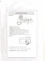
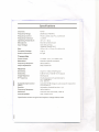
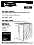
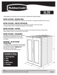
-~
PRO501 XL
Citizens Band Radio
I
Australian Edition
I
unidE!n°o
OPERATING GUIDE
i
-----.
--
- -_.-
Introduction
Welcome to the world of CB radio communication. Your Uniden PRO501XLrepresents
the most advanced portable radio ever designed for use in the Citizens Band Radio
Service. This powerful unit operates on any of the 40 AM frequencies authorized by the
Spectrum Management Agency (SMA).
Among its many features, the PRO501XLincludes:
Superheterodyne circuitry to enhance receiver quality.
. Phase Locked Loop Synthesizer techniques to assure precise frequency control.
. Built-in Automatic N9ise Limiter
.
This radio has been type accepted and fully certified by the SMA.
WARNING
The Citizen Band Radio Communication Service (CBRS) is under the jurisdiction of
the Australian Spectrum Management Agency (SMA). Any adjustment or alteration
which will change the performance of the transceiver's original SMA type acceptance
is STRICTLY PROHIBITED. Replacement or substitution of power or frequency
determining components e.g. Crystals, Transistors, IC's, Diodes, or any part of a
unique nature, with parts other than those recommended by Uniden may cause
violation to the SMA type acceptance technical requirement.
Licensing Requirements
Before using your tranceiver, you must obtain a Citizen Band Radio License f~om the
Spectrum Management Agency (SMA). Application forms and brochures relating to
CBRS are available at your nearest SMA office. Mail the completed application form
and the appropriate fee to the Communications Manager of SMA, in the State or
Territory in which the station will be operated
Unpacking Your CB Radio
..
The following items are included with your PRO501XL:
.
PRO501XL
CB Radio
Mounting Bracket Kit
.
.
This Operating Guide
(Read it carefully and save)
.
Microphone Hanger Clip
Australian Warranty Program
and Product Registration Form
The following items are included with your PRO501AXL:
.
.
.
PRO501AXL
CB Radio
Microphone Hanger Clip
Magnetic Mount Antenna
MountingBracketKit
.
.
.
Cigarette Lighter Adapter Plug
This Operating Guide (Read it carefully
and save)
AustralianWarranty Program
and Product RegistrationForm
If any items are missing or damaged, contact your place of purchase immediately.
sure to complete and mail in the Product Registration Card.
Features, Specifications
change without notice.
Be
and availability of Optional Accessories are all subject to
Uniden@ is a registered trademark of Uniden Corporation.
@ 1994 Uniden Australia
UTUDO 1348BA
Pty. Limited. All rights reserved.
Printedin the Phil-ippines
-'
-
;:::;::;
Operation
Before operating the PRO501 XL:
1. Be sure you read and understand SMA Rules and Regulations.
2. Be sure that the power cord, microphone and antenna are properly connected.
3. Turn the power on by sliding the PWR switch to ON.
Receive
1. Use the CHANNEL SELECTOR buttons to select any of the 40 channels.
2. Set the VOLUME control to a comfortable
listening level.
3. Adjust the SQUELCH control to eliminate background noise during the absence of a
signal. Rotate SQUELCH to the right until the noise disappears (no signal should be
present). Leave the control at this setting. The receiver will remain quiet until a
signal is actually received.
Note:
Do not advance the control too far, or some weaker signals willnot be heard.
Transm it
1. Set the CHANNEL SELECTOR to the desired channel.
2. If the channel is clear, press the Push-To-Talk
to speak clearly into the microphone.
Button on the microphone.
Be sure
IMPORTANT:
All channels, except channel 9, may be used for normal communication. Channel 9 is reserved for emergency communications involving the immediate
safety of individuals or the protection of property.
This is a rule and applies to all operators of CB radios.
Emergency Operation
1. Press the CHANNEL SELECTOR buttons to reach Channel 9. If the channel is
clear, press the Push-to-Talk switch on the microphone to talk Hold the
microphone a few inches away and speak clearly.
2. It is possible that your present location is out of range to those who monitor
Channel 9. If there is no response to your emergency call on Channel 9, set the
CHANNEL SELECTOR to find an active channel. Ask the party on that channel for
assistance in relaying your emergency message on Channel 9 in their area.
Rules You Should Know
When operating your CB, there are a few important rules to observe:
.
It is prohibited to blast others off the air by Qverpowering them with illegally
amplified transmitter power.
.
.
You must not use the CB to promote illegal activities.
It is illegal to use profanity.
.
You may not play music in your CB.
.
You may not use yourCB
to sell merchandise or professional services.
-----...
i
I
'==
PRO501 AXLAccessories
To connect the Cigarette LighterAdapter Plug:
IMPORTANT:
The Cigarette Lighter
Adapter Plug
is designed
to be used ONLY with
negative ground vehicles. Do not attempt to operate the unit with the
Adapter Plug connected to a positive ground vehicle.
1. Remove the screw from the top half of
the plug shell (Be careful not to lose
the hex nut).
2. Carefully separate the two halves
of the plug shell.
t
3. Strip 1/5 inch of insulation from each
wire end.
--t
~
CrImp on Insulation
4. Crimp the terminals onto the wire
ends as shown.
i"
Black
Red
5. With the wires attached, insert the
terminals into the plug shell.
Note
The black wire is inserted in the
section of the shell marked
negative (-). The red wire is
inserted into the section of the
shell marked positive (+).
6. Join the two halves of the plug shell. Secure the plug shell with the screw and hex nut.
Attaching the MagneticMountAntenna
1. Place the antenna in a convenient location on your vehicle.
2. Route the antenna cable through your vehicle's window, door, or other opening into
the interior of the vehicle.
3. Attach the antenna cable to the terminal on the rear of the PRO501 AXL.
Note:
Be sure to route the antenna
your vehicle.
where it will not interfere with the operation
J
of
r
-
--
---
Controls And Functions
Front Panel
9
4
765
1. PWR Turns the unit on and off.
2.
3.
4.
5.
6.
7.
8.
9.
VOLUME Adjusts the volume level.
SQUELCH Adjusts the squelch level.
Channel Selector Selects any of the 40 CB channels.
TX Indicator LED lights to indicate when the radio is transmitting.
Channel Display A large LED shows the current channel in use.
Speaker Produces audible signals from incoming trransmissions.
Microphone Transforms into transmission signals.
Push-to-Talk Button Switches the CB from receive to transmit mode.
Rear Panel
10
10. Antenna connector
11 12
Provides a connection for an antenna.
11. Power Cord Connects to a vehicle's 12V negative ground electrical system.
12. Mounting Bracket
A mounting kit is included with the radio.
--.
,..
~
---
I1
I
Installation
Connecting the Power Cord
WARNING
This radio can be used only in vehicles with a negative ground electrical system.
Connecting this unit to a positive ground electrical system will result in serious
damage to the radio.
1. Check the vehicle battery connections to determine which battery terminal (positive
or negative) is grounded to the engine block or chassis. Most of today's automobiles
are negative ground.
2. Connect the RED wire of the DC power cord to the accessory contact in your
vehicle's +13.8 VDC fuse box.
3. Connect the BLACKwire of the DC power cord to the negative side of the automobile
(usually the chassis).
~
Mounting the Microphone Hanger
Mountthe microphone hanger on the side of the
radio. Mounting holes are provided on the
right-hand side of the unit. Use the screws
supplied. You can also mount the hanger on the
dashboard if preferred.
Mounting the Radio Bracket
00
The design of the PRO501XLMounting Bracket
allows you to mount the radio in one of three angles for easy viewing of the front panel.
Note:
The speaker is located on the bottom of the radio. Be sure the mounting
location does not obstruct this area.
Note:
Mount the radio to the bracket only after the wiring has been connected to the
rear panel and the microphone hanger has been installed
1. First select an ideal location in yo~r vehicle to mount the PRO501XL. Make sure the
location will not interfere with your driving. In a passenger car, the ideal installation
is underneath the dashboard on the passenger side.
2. Remove the mounting bracket from the radio and use it as a template for marking
the location of the mounting screws. (Note: If there are screws already holding the
dashboard, you can use the same screw holes to mount the bracket in its place.)
3. Drill the necessary holes and secure the mounting bracket in place using the screws
provided.
,...----
.:;
]
--
~
---..
_.
;;:;I:
4. Secure the radio to the mounting bracket with
the provided mounting knobs (2).
5. To mount the radio at an angle:
.
.
.
Loosen the mounting knobs.
Tilt the radio.
Tighten the mounting knobs.
Connecting the Microphone
Plug the Microphone Cord connector into the jack on the left-hand side of the radio.
Connecting the Antenna
Connect the CB antenna plug to the ANT. jack on the rear panel. (For more information
on antenna installation, please refer to the instruction guide that came with your
antenna.)
CB Antenna TIps
.
In mobile installations (cars, trucks, or boats, etc.), use a non-directional
system for maximum transmitting and receiving performance.
.
A vertically polarized, quarter-wavelength whip antenna provides the most reliable
operation and greatest range.
A 3-way combination antenna allows you to operate all three bands (AM, FM, and
CB) with one antenna. However, it will provide a far less transmitting and receiving
range than a standard "single band" antenna designed for CB use only.
.
.
antenna
The shorter loaded-type whip antennas are more attractive and compact than the
larger full quarter-wavelength whip. However, the shorter antennas will not provide
the maximum transmitting and receiving range that is possible with the larger ones..
r
Specifications
Channels:
Frequency Range:
Frequency Control:
Frequency Tolerance:
Operating Temperature:
Microphone:
Input Voltage:
40AM
26.965 to 27.405 MHz
Phase Locked Loop (PLL) synthesizer
:t 0.005%
Size:
-30 °c to + 60°C
Electret Condenser type
13.8 VDC nominal
Negative Ground ONLY
120mm (W) x 170mm (D) x 40mm (H)
Complete Package:
Antenna Connector:
0.46 kg.
M-Type
Transm iller
Power Output:
Modulation:
Frequency Response:
Output Impedance:
Receiver
Sensitivity:
Selectivity:
ImageRejection:
IFFrequency:
I
Automatic Gain Control
(AGC):
Squelch:
Frequency Response:
Distortion:
Internal Speaker:
Specifications
I
2.8 Watts (nom), 4.0 Watts (max)
Class B amplitude modulation
300 to 2500 Hz
50Q unbalanced
O.5JlV for 10 dB; (S+N)/N typical
6 dB @ 7 kHz, 70 dB @ 10kHz typical
80 dB typical
Double Conversion Superheterodyne
1st: 10.692 MHz
2nd: 450 kHz
Less than 10 dB change in audio output for inputs from
10 to 50,000 JlV
Adjustable; threshold less than 1 JlV
300 to 2000 Hz
Less than 10% at 0.4 watts, 1000 Hz
16Q, 3 watts round
shown are typical and subject
to change
without notice.
--
== ;0
<::::
Troubleshooting
If the PRO501XLdoes not perform to your expectations,
suggestions listed below.
Problem
..
.
.
..
Unit does not power on.
Poor reception.
Weak Transmission.
please try the troubleshooting
Suggestion
Check the wiring connections.
Check the in-line fuse.
Check the vehicle electrical system.
Check and adjust the SQUELCH.
Check the antenna connect;ons.
Check the antenna connections.
Servicing Your CB
If you determine that service is necessary, contact your local dealer or return the unit
in its original carton to Uniden - Service Division. Ship the item with a brief and
concise description of the problem, your name, address, a telephone number where
you can be reached during working hours and a copy of the original purchase receipt
to the address listed in the warranty (at the end of this manual).
Technical information. diagrams. and charts are available upon request. It is the user's
responsibility to see that this radio is operating at all times in accordance with the SMA
Citizens Band Radio Service regulations. We highly recommend that you consult a qualified
radiotelephone technician for service and alignment of this radio.
When ordering parts, please specify the correct model number and serial number of this
radio.
Please refer to the 'WARNING"
information at the front of this manual.
Care and Maintenance
The PRO501XLis designed to give you years of trouble-free service. There are no
user-serviceable parts inside and, except for the fuse in the DC power cord, no
maintenance is required.
Note:
Do not expose the unit to moisture. Rain, dew, road splash, or other liquids
may damage
the internal components.
Replacing the Fuse in the DC Power Cord
The in-linefuse holder contains a 2~arrpere fuse to protect the radio from power surges.
To inspect or replace a blown fuse:
1. Press the ends of the fuse holder together and twist counterclockwise. Carefully
separate the two halves.
2. Remove the fuse and inspect. If blown replace it with the same type.
3. Replace fuse inside the holder and reassemble the two halves by pressing the ends
together and twisting c1ockwise.
..
~
r
=Warranty
Unlden PRO501XL CB Radio Australian 2 Year Warranty.
(Accessories are covered for 90 days only).
Note: Please keep your sales docket as it provides evidence of warranty.
WARRANTOR: Uniden Australia Pty. Ltd. ACN 001 885 498
ELEMENTS OF WARRANTY:Uniden warrants to the original retail owner for the
duration of this warranty, its PRO501XL CB Radio (hereinafter referred to as the
Product), to be free from defects in materials and craftmanshipwith only the limitations
or exdusions set out below.
WARRANTY DURA110N: This warranty to the original user only shall terminate and be
of no further effect Two (2) years after the date of original retail sale. This warranty will be
deemed invalid if the product is (A) Damaged or not maintained as reasonable and
necessary,
(B) Modified, altered, or used as part of any conversation
kits,
subassemblies, or any configurations not sold by Uniden, (C) Improperly installed, (D)
Repaired by someone other than an authorized Uniden Repair Agent for a defect or
malfunction covered by this warranty, (E) Used In conjunction with any equipment or
parts or as part of a system not manufactured by Uniden, (F) Installed, programmed or
serviced by anyone other than an authorized Uniden Repair Agent, (G) Where the
Serial Number label of the product has been removed or damaged beyond recognition.
PARTS COVERED: This warranty covers for 2 years; the PRO501 XL Transceiver unit
and Microphone only. All other accessories like Mounting Bracket, Mic Hanger, Leads,
Screws, Magnet Mount Antenna (PRO501AXL
(PRO501 AXL only), are covered for 90 days.
only),
and
Cigarette
Ughter
Plug
STATEMENT OF REMEDY: In the event that the product does not conform to this
warranty at anytime while this warranty is in effect, the warrantor will at its discretion,
repair the defect or replace the product and return it to you withoutcharge for parts or
service. THIS WARRANlY DOES NOT COVER OR PROVIDE FOR THE
REIMBURSEMENT OR PAYMENT OF INCIDENTAL OR CONSEQUENTIAL
DAMAGES.
WARRANTY CARD: If a warranty card had been included with this product, then please
fill it in and retum it to us within 1 4 days of purchase. Your name and the serial number of
the product will then be registered in our database and this will help us to process your
claim with greater speed and efficiency should you require warranty service.
PROCEDURE FOR OBTAINING PERFORMANCE OF WARRANTY: In the event that
the Product does not conform to this warranty, the Product should be shipped or
delivered,freight pre-paid,withevidence of original purchase, ( eg/ a copy of the sales
docket), to the warrantor at:
UNIDEN AUSTRALIA PTY. LTO.- SERVICE DIVISION
345 Princes Highway, Rockdale, NSW 2216
Ph( 02) 599 3100 Fx (02) 599 3278
Customers in other States should ship or deliver the Product
freight pre-paid to their nearest Unlden Authorized Repair Centre.
(Contact Uniden for the nearest Warranty Agent to you).
--~