1
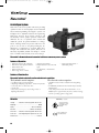
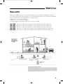
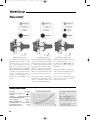
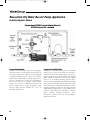
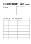
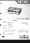
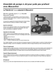
Pump Catalog 063-090 Accessories.qxp
3/16/2009
10:03 AM
Page 63
Accessories
• Mascontrol
• Controlpres
• Well Tanks
• Expansion Tanks
• MonoDrive
• SubDrive
• Pumptec
• Pumptec Plus
63
Pump Catalog 063-090 Accessories.qxp
3/16/2009
10:03 AM
Page 64
Mascontrol
An intelligent system
Mascontrol is the newest product innovation providing
optimum control for electric pumps used in residential
and commercial plumbing and irrigation systems. An
intelligent mix of hydraulic and electronic engineering,
Mascontrol monitors both pressure and flow and
automatically controls pump operations. Mascontrol
eliminates the use of expansion tanks needed with
traditional systems. No plenum chambers to recharge,
and no irritating variations in pressure and flow at the
point of use. No risk of the pump running dry. No
adjustment or maintenance is required. Much more
compact than traditional tank systems, Mascontrol is
absolutely dependable, durable and simple to install.
Over one million units currently in use across Europe.
Mascontrol is the most advanced economical solution for controlling electric pumps.
Features of Operation
•
•
•
•
•
Eliminates pressure tank and switch
Maintains constant pressure and flow
Built-in check valve
Built-in run-dry sensor
Dual voltage 115 V or 230 V
• Absorbs water hammer
• Simple installation saves time and
space
• No adjustment or maintenance
required
• Can be used with surface or
submersible pumps
Features of Construction
Mascontrol includes a hydraulic section and electronic control box.
The hydraulic section comprises:
The electronic section comprises:
• a molded housing in reinforced plastic.
• a diaphragm and spring responsive to variations in pressure.
• a valve responsive to variations in flow.
• a check valve
• safety valve preventing any water leakage in case of
diaphragm break down
• a NEMA 12 electronic box molded in self extinguishing
plastic.
• an individually-tested electronic circuit board protected by
insulating film.
• a relay with special contacts and an electrical life of over
300,000 cycles or approximately 10 years (continuous rating).
• a varistor protecting against voltage peaks.
Materials
Housing ................Glass fiber reinforced polyamide PA 6 FV 30%
Diaphragm ............................................................................EPDM
Spring ............................................................Steel C 72 UNI 3545
Warranty - 2 years
Listed by Underwriters
Laboratories Inc. to U.S.
and Canadian safety
standards
Flow valve.................................................Stainless steel AISI 304
Check valve..........Glass fiber reinforced polyamide PA 6 FV 30%
Control box..........Self extinguishing thermoplastic resin 94 - 5 VA
Printed circuit....................................................................Vetronite
64
Fully in compliance with
current EEC directives
Pump Catalog 063-090 Accessories.qxp
3/16/2009
10:03 AM
Page 65
Mascontrol
Mascontrol is available in 1" and 1-1/4" models. By utilizing a bypass, the Mascontrol is adaptable to almost any
flow and horse power pump. Product warranty is two years from installation date (see footnote below). Replacement
parts are the electronic box and hydraulic body - no rebuilds required.
• Mascontrol 1" - for flows up to 15GPM
• Mascontrol 1-1/4" - for flows up to 25GPM
• Use bypass application with either model for flows in excess of 25 GPM.
Item # 79980
Item # 79983
Item # 79984
Item # 79985
Item # 79986
Mascontrol, 1" NPT, 50 feet (suitable for 50 feet maximum elevation above Mascontrol)
Mascontrol, 1" NPT, 70 feet (suitable for 70 feet maximum elevation above Mascontrol)
Mascontrol, 1" NPT, 90 feet (suitable for 90 feet maximum elevation above Mascontrol)
Mascontrol, 1-1/4" NPT, 50 feet (suitable for 50 feet maximum elevation above Mascontrol)
Mascontrol, 1-1/4" NPT, 70 feet (suitable for 70 feet maximum elevation above Mascontrol)
65
Pump Catalog 063-090 Accessories.qxp
3/16/2009
10:03 AM
Page 66
Mascontrol
The system’s easy operating steps are
displayed by indicator lights on a small
panel at the front of the control box.
Two of these will light up when the
Mascontrol is connected to the power
supply: Power on (green) and Pump
on (yellow), indicating that the circuit is
powered up and the pump is running
(see Fig. 1). The pump will continue to
operate for a few seconds so that
pressure can be established in the
system.
Technical Specifications
Dual voltage . . . . . . . . . . . . . . . 115V / 230V
Acceptable power fluctuations . . . . . . + 10%
Frequency . . . . . . . . . . . . . . . . . . . . 50/60 Hz
Amp rating . . . . . 115V-16FLA / 230V-20FLA
Use starter for higher amp draws
Electronic enclosure . . . . . . . . . . . NEMA 12
Maximum operating pressure . . . . . 116 PSI
Operating temperature . . 32-149°F (0-65°C)
Male threaded connections . . . . . . . . 1" NPT
Electrical conduit connections . . . . . . . . 1/2"
66
At this point, the pump is automatically
shut off and switched to the standby
mode (green light on), ready to respond
to the various monitoring and control
signals generated by the system (Fig. 2).
Whenever a tap or valve is opened, the
pump is immediately started by the
Mascontrol unit and continues to run as
long as the tap remains open (Fig. 1).
Irregular operating conditions such as a
dry or blocked inlet line, etc., are
recognized by the Failure light (red
light on). The pump is shut off
immediately.
When the tap is closed, the Mascontrol
unit shuts off the pump and returns the
system to maximum pressure and
reverts to the standby mode (Fig. 2).
If power is lost, the Mascontrol system
will reset and restart automatically
when power is restored.
Once the problem is corrected the user
need only press the red Restart button
to restore normal operation (Fig. 3).
Pump Catalog 063-090 Accessories.qxp
3/16/2009
10:03 AM
Page 67
Mascontrol Installation Diagram
Surface Pump - Residential Application
OPTIONAL:
2.1 gallon gross
volume (GV)
pressure tank.
Precharge at 35 to
40 psi.
The pressure tank is optional. The tank, if used,
provides a “cushion” for small demands such as
icemakers, reverse osmosis systems, leaks, glasses
of water, etc. The tank precharge should be set at
35 to 40 PSI or generally not less than 20 PSI
below the system pressure. With single stage
surface pumps, system pressure is usually between
50 and 60 PSI. Do not install a pressure tank larger
then 8.6 gallons gross volume as the system may
perform like a standard tank set-up. Be sure to
install a ball valve on the main after the Mascontrol
for system maintenance. Gate valves may be used
instead of ball valves. Remove the pressure switch
from the pump (if supplied) and wire the
Mascontrol directly to the pump.
Submersible Pump - Residential Application
2.1 gallon gross volume (GV)
pressure tank for up to 2.5
bathrooms. 4.5 gallon (GV) for
3+ bathrooms. Precharge at 35
to 40 psi.
The submersible system may be operated without
a tank for 3-wire submersible systems, however
the tank provides a “cushion” for small demands
such as icemakers, reverse osmosis systems, leaks,
glasses of water, etc. The tank precharge should be
set at 35 to 40 PSI or generally not less than 20 PSI
below the system pressure. Do not install a
pressure tank larger then 8.6 gallons gross volume
as the system may perform like a standard tank setup. Irrigation systems do not require a tank unless
the system has significant leaks. The pressure
reducing valve provides safe water pressures to the
house as submersible pumps are usually capable of
producing significantly higher pressure than is
needed for the home or application.The ball valves
shown are for system maintenance. At least one
ball valve should be placed after the Mascontrol
on the main. Gate valves may be used instead of
ball valves.
PRV not required with Controlpres. Be sure all pipe &
fittings are capable of handling the maximum pressure of
the pumps.
67
Pump Catalog 063-090 Accessories.qxp
3/16/2009
10:03 AM
Page 68
Mascontrol City Water Booster Pump Application
Isolation Bypass Shown
Diagram shows OPTIONAL Pressure Reducing Valve and
OPTIONAL Pressure Tank - See below
Pressure Reducing Valve Required only if incoming city pressure PLUS pump’s
maximum pressure exceeds desired service pressure. If
city pressure fluctuates use highest pressure reading and
use pump’s maximum pressure to arrive at total surface
pressure. Most residential booster pumps will generate at
least 50 to 55 PSI. Follow local codes on maximum inhouse water pressure. If irrigation requires higher
pressure, tee off after the Mascontrol but before the
pressure reducing valve to supply the irrigation system
with the highest pressure available. Do not tee off
BEFORE the Mascontrol
68
Pressure Tank and Relief Valve OPTIONAL - The Mascontrol provides “on demand”
pump control. To prevent the pump from starting for
small water uses such as ice makers, glasses of water, etc.,
install a 2.1 gallon gross volume pressure tank (example
PJR6) AFTER the Mascontrol and pressure reducing
valve (if one is installed). Precharge pressure tank to
between 35 and 40 PSI, BUT NOT LESS THAN 20 PSI
below system pressure. DO NOT install pressure switch.
The tank will “feed” small demands. When the tank is
emptied, the Mascontrol will start the pump and repeat
pump cycling. On larger homes (3 or more bathrooms) a
4.5 gross volume tank may be used,such as a WX102,
JR15 or WM18L. Precharge according to above
instructions. A pressure relief valve may be added as
dictated by local code.
Pump Catalog 063-090 Accessories.qxp
3/16/2009
10:03 AM
Page 69
Mascontrol Bypass Application
With 1” Mascontrol use on flows above 15 GPM
With 1-1/4” Mascontrol use on flows above 25 GPM
Ball valve #1 is used to provide back-pressure to the pump and also
to throttle more water into the bypass if necessary. Pressure reducing
valve shown on submersible is used when maximum head pressure is
greater desired system pressure. In most cases, a pressure reducing
valve will be required as most submersibles are capable of generating
much more PSI than is required, especially with varying flow rates. If
rapid cycling occurs, the bypass/Mascontrol is not getting enough
flow and ball valve #1 should be adjusted (more closed) to force
additional water into the bypass. Note that as less of the pump’s
capacity is used, flow slows down/pressure increases and water will
follow the least resistant path - the main line. Fast cycling on a
particular zone (when the other zones run normal) usually indicates
an undersized zone. Check the pressure gauge to see if pressure rises
significantly on the cycling zone.
PRV not required with Controlpres.
69
Pump Catalog 063-090 Accessories.qxp
3/16/2009
10:03 AM
Page 70
Mascontrol Installation with Aerator Tank
Surface Pump Application
Optional 2.1 gallon JR6
pressure tank precharge set
at approx. 40 PSI.
Submersible Pump Application
Optional 2.1 gallon JR6
pressure tank precharge set
at approx. 40 PSI.
2 wire pumps must have a tank installed.
PRV not required with Controlpres.
70
Pump Catalog 063-090 Accessories.qxp
3/16/2009
10:03 AM
Page 71
Controlpres
Constant Pressure - Constant Flow
Controlpres, a newer version of the Mascontrol
valve, has all of the same innovative features as
the original plus a built-in pressure-reducing
valve, allowing for downstream pressure
adjustments according to system requirements.
Pressure gauge, 1/4"
FNPT is sold separately
Item #79992 - Controlpres, 1-1/4" NPT
• 2 year warranty
Features of Operation & Construction
Technical Specifications
• Provides for an adjustable down stream pressure
between 36 psi to 100 psi
• Eliminates the need for a pressure tank and switch
• Unit maintains constant pressure, constant flow
• Built-in check vale
• Run-dry sensor for pump protection
• Dual voltage 115/230 with additional voltage
requirements accommodated by the use of a
contactor
• Time and space are saved by simple installation
requirements and the unit’s compact size
• Can be utilized on virtually all pumps
Dual voltage.....................................................115V/230V
Acceptable power fluctuations................................+10%
Frequency ...........................................................50/60 Hz
Amp rating .........................115V-16 FLA/230V-20 FLA
Use contractor for higher amp rating
Electronic enclosure .........................................NEMA 12
Maximum inlet pressure .........................................145 psi
Factory pressure setting.........................................43.5 psi
Pressure adjusting range......................36.2 psi, 101.5 psi
Male threaded connection ............................1-1/4" NPT
Pressure gauge male threaded connection.............1/4" NPT
71
Pump Catalog 063-090 Accessories.qxp
3/16/2009
10:03 AM
Page 72
AQUA FLO Well Tanks
A full range of pressure tanks is available in the
AQUA FLO line to complete your water system.
Aqua Flo tanks are the industry’s fighting brand and one of the more popular water tanks on the market. Efficient and
cost-effective, Aqua Flo tanks are designed with a patented controlled action, double diaphragm assembly that is
completely contained in a pre-pressurized air cushion that reduces condensation and regulates diaphragm action.
Aqua Flo tanks have a threaded nut for easy installation of pump
stand, a welded malleable elbow and an adjustable air charge. Clean,
airtight welds are achieved using the most modern welding equipment
available. They are completed with an appliance quality paint finish
over primer coat, which combines durability and high luster.
Our diaphragms are constructed with a FDA approved high grade
butyl. The true airflow design means fewer problems with
condensation. Our diaphragms positive lock internal clench ring
cannot slip and does not rely on the tank wall. The tank contains a
stainless steel port diffuser, and water connection which directs water
flow upward and outward while locking the lower diaphragm in place.
All of our quality tanks are backed by a five year written, limited
warranty. Aqua Flo tanks are quality tested at four different stages on
the production line. Tests include helium and high pressure tests to
ensure the structural integrity of every tank.
Double Diaphragm Design
• 100% Butyl Water Chamber incorporates different size diaphragms on various tank sizes
and handles chlorine. The double diaphragm will not deteriorate to chlorinated water.
• The water chamber is totally independent of the tank wall so that diaphragms are sized
according to application.
• Steel clench ring regulates action and prevents diaphragm from rubbing against tank wall.
• The design provides a unique anti-condensation feature.
• High quality two part polyurethane finish the best in the industry.
• Integral tank skirt will easily accommodate water systems industry standard tank tees.
Model AF AquaFlo® Tanks - Quick Sizing Drawdown in Gallons/Liters - Maximum Working Pressure 125 PSI
Item
#
33290
33291
33299
33292
33297
33293
33294
33298
33295
33296
Model
AF44
AF66
AF88
AF111
AF122
AF144
AF211
AF244
AF266
AF366
Total Tank @ 20/40
Volume
PSI
(Gal/Liters) (Gal/Liters)
14/60
5.6/21.35
20/80
8.1/30.51
26/100
10.5/39.66
32/120
12.9/48.81
33/130
13.3/50.34
44/170
17.7/67.12
62/240
25.0/94.57
81/310
32.6/123.6
85/325
34.3/129.7
119/450
48.0/181.5
@ 30/50
PSI
(Gal/Liters)
4.8/18.1
6.8/25.8
8.9/33.6
10.9/41.3
11.3/42.6
15.0/56.8
21.1/80.0
27.6/104.5
29.0/109.7
40.6/153.6
@ 40/60
PSI
(Gal/Liters)
4.1/15.6
5.9/22.3
7.7/29.0
9.4/35.7
9.7/36.8
13.0/49.1
18.3/69.2
23.9/90.4
25.1/94.9
35.1/132.9
Maximum working temperature for all Well Tanks listed on the page is 140°F (60°C).
72
Dimensions
Diameter
Height
(inches)
(inches)
16
22
16
29
16
34.5
21
27.75
16
42.75
21
36.25
21
48
21
62
26
44.5
26
59.75
System
Connection
PSI
Precharge
1"
1"
1"
1-1/4"
1"
1-1/4"
1-1/4"
1-1/4"
1-1/4"
1-1/4"
38
38
38
38
38
38
38
38
38
38
Shipping
Weight
(Lbs)
28.0
36.0
41.0
54.0
49.0
67.0
82.0
99.0
121.0
153.0
Pump Catalog 063-090 Accessories.qxp
3/16/2009
10:03 AM
Page 73
Not Available
in USA
Well-Rite® Series Well Tanks
Well-Rite® tanks are quickly becoming the industry standard. This tank is loaded with features that distinguish it
from the competition. Solidly constructed with a welded, stainless steel connection, the Well-Rite® Series puts the
“tank” in water tank. Well-Rite® tanks are distinctly designed with Flexcon's patented and innovative controlled
action diaphragm (“CAD”), which eliminates coatings, liners and plastic bladders.
The CAD is surrounded in a pre-pressurized atmosphere that reduces condensation and forces the diaphragm to
expand and contract the same way, every time. Flexcon's patented controlled action, double diaphragm assembly
completely contains drawdown water. The water chamber does not chafe on the tank wall. This unique diaphragm
design is constructed with an FDA approved, high-grade butyl rubber compound. NSF certifies Well-Rite® tanks as
conforming to standard 61 for drinking water system components. The CAD system is anchored by Flexcon's
stainless steel water connection which is totally
lead free and NSF approved for the highest
sanitary standard. A full flow stainless steel port
diffuser directs water flow upward and outward
while firmly locking the lower diaphragm in place.
Well-Rite® tanks are finished with a high-quality
urethane paint system that combines durable allweather protection with a deep gloss, appliance
look.
All of Flexcon's quality tanks are backed by a five
year written limited warranty. Well-Rite® tanks are
quality tested at four different stages on the
production line. Tests include helium and high
pressure tests to ensure the structural integrity of
every tank.
Welded Stainless Steel Connection
Well-Rite Series - Quick Sizing Drawdown in Gallons/Liters - Maximum Working Pressure 125 PSI
Item
#
33180
33181
33182
33183
33184
33185
33186
33187
33188
33189
Model
WR45R
WR60R
WR80R
WR100R
WR120R
WR140R
WR200R
WR240R
WR260R
WR360R
Total Tank
@ 20/40
@ 30/50
Volume
PSI
PSI
(Gal/Liters) (Gal/Liters) (Gal/Liters)
14/60
5.6/21.35
4.8/18.1
20/80
8.1/30.51
6.8/25.8
26/100
10.5/39.66
8.9/33.6
32/120
12.9/48.81 10.9/41.3
33/130
13.3/50.34 11.3/42.6
44/170
17.7/67.12 15.0/56.8
62/240
25.0/94.57 21.1/80.0
81/310
32.6/123.6 27.6/104.5
85/325
34.3/129.7 29.0/109.7
119/450
48.0/181.5 40.6/153.6
@ 40/60
PSI
(Gal/Liters)
4.1/15.6
5.9/22.3
7.7/29.0
9.4/35.7
9.7/36.8
13.0/49.1
18.3/69.2
23.9/90.4
25.1/94.9
35.1/132.9
Dimensions
System
Diameter Height Connection
(inches) (inches)
Union
16
22
1"
16
29
1"
16
34.5
1"
21
27.75
1-1/4"
16
42.75
1"
21
36.25
1-1/4"
21
48
1-1/4"
21
62
1-1/4"
26
44.5
1-1/4"
26
59.75
1-1/4"
PSI
Precharge
38
38
38
38
38
38
38
38
38
38
Shipping
Weight
(Lbs)
28.0
36.0
41.0
54.0
49.0
67.0
82.0
99.0
121.0
153.0
Maximum working temperature for all Well Tanks listed on the page is 140°F (60°C).
73
Pump Catalog 063-090 Accessories.qxp
3/16/2009
10:03 AM
Page 74
Well-Rite Online® Series Well Tanks
Not Available
in USA
Well-Rite Online® tanks are the professional's choice in the well tank market. Flexcon's innovative Online Union
Connection is easier to install and saves time and money. You simply line up your storage tank “T” and tighten the
union nut with the Well-Rite Online tank standing upright - avoiding any need to tip the tank over. Online has a
welded, stainless steel connection. This stainless steel connection is totally lead free and NSF approved for the
highest sanitary standard. Well-Rite Online tanks are finished with a high quality urethane paint system. The paint
system combines durable all-weather protection with a deep gloss appliance look. Well-Rite Online® tanks are
designed with Flexcon's patented and innovative controlled action diaphragm, which eliminates coatings, liners and
plastic bladders.
Well-Rite Online® tanks' patented controlled action diaphragm
assembly completely contains drawdown water in a pre-charged air
atmosphere. This “air buffer” design means fewer problems with
condensation and with the clench ring prevents the water chamber
from chafing against the tank wall. The unique diaphragm design is
constructed with a FDA approved, high-grade butyl rubber
compound. NSF certifies Well-Rite Online® tanks as conforming to
standard 61 for drinking water system components. A full flow
stainless steel port diffuser directs water flow upward and outward
while firmly locking the lower diaphragm in place.
All of Flexcon's quality tanks are backed by a
five year written limited warranty. Well-Rite®
tanks are quality tested at four different stages on
the production line. Tests include helium and
high pressure tests to ensure the structural
integrity of every tank.
Brass Online Tank Tees
The Well-Rite Online® Union
Connection with optional tank “T”
The Well-Rite Online® tank
includes tail piece.
Welded Stainless Steel Connection
#33268: OLT-100,
1" Male Connection
#33269: OLT-125,
1-1/4" Male Connection
Well-Rite Online Series - Quick Sizing Drawdown in Gallons/Liters - Maximum Working Pressure 125 PSI
Item
#
33190
33191
33192
33193
33194
33195
33196
33197
33198
33199
Model
WR45-OLC
WR60-OLC
WR80-OLC
WR100-OLC
WR120-OLC
WR140-OLC
WR200-OLC
WR240-OLC
WR260-OLC
WR360-OLC
Total Tank
@ 20/40
@ 30/50
Volume
PSI
PSI
(Gal/Liters) (Gal/Liters) (Gal/Liters)
14/60
5.6/21.35
4.8/18.1
20/80
8.1/30.51
6.8/25.8
26/100
10.5/39.66
8.9/33.6
32/120
12.9/48.81 10.9/41.3
33/130
13.3/50.34 11.3/42.6
44/170
17.7/67.12 15.0/56.8
62/240
25.0/94.57 21.1/80.0
81/310
32.6/123.6 27.6/104.5
85/325
34.3/129.7 29.0/109.7
119/450
48.0/181.5 40.6/153.6
@ 40/60
PSI
(Gal/Liters)
4.1/15.6
5.9/22.3
7.7/29.0
9.4/35.7
9.7/36.8
13.0/49.1
18.3/69.2
23.9/90.4
25.1/94.9
35.1/132.9
Maximum working temperature for all Well Tanks listed on the page is 140°F (60°C).
74
74
Dimensions
System
Diameter Height Connection
(inches) (inches)
Union
16
22
1"
16
29
1"
16
34.5
1"
21
27.75
1-1/4"
16
42.75
1"
21
36.25
1-1/4"
21
48
1-1/4"
21
62
1-1/4"
26
44.5
1-1/4"
26
59.75
1-1/4"
PSI
Precharge
38
38
38
38
38
38
38
38
38
38
Shipping
Weight
(Lbs)
28.0
36.0
41.0
54.0
49.0
67.0
82.0
99.0
121.0
153.0
Pump Catalog 063-090 Accessories.qxp
3/16/2009
10:03 AM
Page 75
Jet-Rite 2 Well Tanks
Jet-Rite 2 tanks are ideally suited for irrigation applications, booster systems, shallow jet pumps and centrifugal pump
configurations. The Jet-Rite 2 series is constructed with a single butyl diaphragm and polypropylene liner assembly
that completely contains drawdown water. The diaphragm is constructed with an FDA approved, high-grade butyl
rubber compound. Jet-Rite 2 tanks are made with a stainless steel system connection, are available in vertical and
horizontal models and are finished with an appliance quality paint especially suited for outdoor installations.
Jet-Rite 2 tanks are quality tested at several stages on the production line to ensure the structural integrity of every
tank.
All of Flexcon's quality tanks are backed
by a five year written limited warranty.
Features:
• Stainless Steel Water Connection
• Virgin Polypropylene Liner
• 100% Butyl Diaphragm
• Appliance Quality Paint Finish
• Brass Air Stem
• Comprehensive Testing
Model PJR In-Line Tanks - Quick Sizing Drawdown in Gallons/Liters - Maximum Working Pressure 125 PSI
Item
#
33285
33286
33287
Total Tank @ 20/40
Volume
PSI
(Gal/Liters) (Gal/Liters)
PJR-6
2.1/8
0.8/2.9
PJR-15
4.8/18
1.7/6.6
PJR-25
8.5/32
3.1/11.7
Model
@ 30/50
PSI
(Gal/Liters)
0.7/2.5
1.5/5.6
2.6/9.8
@ 40/60
PSI
(Gal/Liters)
0.6/2.1
1.3/4.8
2.3/8.7
Dimensions
Diameter
Height
(inches)
(inches)
8
12
11
14.5
12.5
20
System
Connection
PSI
Precharge
3/4"
3/4"
3/4"
28
28
28
Shipping
Weight
(Lbs)
5
10
13
Model PJR Horizontal Tanks - Quick Sizing Drawdown in Gallons/Liters - Maximum Working Pressure 125 PSI
Item
#
33283
33288
33289
33305
Model
PJR-20 (S)
PJR-25 (S)
PJR-44 (S)
PJR-66 (S)
Total Tank
Volume
(Gal/Liters)
5.3/20
8.5/32
14/53
20/80
@ 20/40
@ 30/50
@ 40/60
Dimensions
PSI
PSI
PSI
Diameter
Height
(Gal/Liters) (Gal/Liters) (Gal/Liters) (inches) (inches)
1.9/7.3
1.6/6.2
1.4/5.4
11.4
17.5
3.1/11.7
2.6/9.8
2.3/8.7
12.5
20.0
5.1/19.3
4.3/16.4
3.8/14.2
16.3
20.8
7.6/28.8
6.5/24.8
5.5/20.8
16.3
28.5
System
Connection
PSI
Precharge
3/4"
3/4"
3/4"
1"
28
28
28
28
Shipping
Weight
(Lbs)
13.3
15
28.3
38.0
Maximum working temperature for all Well Tanks listed on the page is 140°F (60°C).
75
Pump Catalog 063-090 Accessories.qxp
3/16/2009
10:03 AM
Page 76
Common Items for Aqua Flo, Well-Rite Online®,
Well-Rite and Jet-Rite 2 Well Tanks
Controlled Action Diaphragm (“CAD”) Operation - 30/50 psi pressure range
1
Pump comes on and
begins to fill the tank.
2
Pump continues to run
compressing air charge in
tank.
3
Pump shuts down when cutout
pressure is reached. Drawdown is
available on demand.
Pump Stands
Item #33301
Model #PS1621 Fits:
Tank Models 44, 45, 60,
66, 80, 88, 120, 122
Item #33300
Model #PS2126 Fits:
Tank Models 100, 111,
140, 144, 200, 211, 240,
244, 260, 266, 360, 366
Threaded nut for easy
installation of pump stand
Adjustable aircharge
Clean, air tight welds are
achieved using the most
modern welding equipment
available
Two part urethane finish
over epoxy primer coat
combines durability and
high luster
Comprehensive pre-charged
air cushion design reduces
condensation and regulates
diaphragm action
Diaphragm of FDA
approved, high grade butyl
Stainless steel port diffuser
directs water flow upward &
outward while locking lower
diaphragm in place
True air flow design means
fewer problems with
condensation
Positive lock, internal clench
ring. Cannot slip...does not
rely on tank wall.
Online® Union Connection
Welded stainless steel connection
Well Tanks Replacement Guide
Aqua
Flo
PJR6
PJR15
PJR20*
PJR25*
AF44
AF66
AF88
AF111
AF122
AF144
AF211
AF244
AF266
AF366
76
WellRite
PJR6
PJR15
PJR20
PJR25
WR45
WR60
WR80
WR100
WR120
WR140
WR200
WR240
WR260
WR360
Well-Rite
H2
Well-X
Wel- Champion
Online
Pro
Trol
Flow
PJR6
N/A
WX-101
WF6
CM1001
PJR15
N/A
WX-102 WF15
CM1002
PJR20
N/A
WX-105
N/A
N/A
PJR25
N/A
WX-103 WF25
CM1003
WR45-OLC WWT-14 WX-201 WF45
CM3001
WR60-OLC WWT-20 WX-202 WF60
CM4202
WR80-OLC WWT-25 WX-202XL N/A
N/A
WR100-OLC WWT-30 WX-205 WF110 CM8205
WR120-OLC WWT-35 WX-203 WF100 CM8003
WR140-OLC WWT-45 WX-250 WF140 CM10050
WR200-OLC WWT-65 WX-251 WF200 CM12051
WR240-OLC WWT-80 WX-255
N/A
N/A
WR260-OLC WWT-85 WX-302 WF260 CM17002
WR350-OLC WWT-120 WX-350 WF360 CM22050
How
2 Tank
HT2
HT4.4
N/A
HT8.6
HT14
HT20
N/A
N/A
HT32
HT44
HT44
N/A
HT86
HT119
Goulds
State
A.O. Smith Perma Tank
V6P
PIL-2
V15P
PIL-5
N/A
N/A
V25P
PIL-7
V45
PAD-14
V60
PAD-20
V80
N/A
N/A
N/A
V100
PAD-36
V140
PAD-52
V200
PAD-52
V250
N/A
V260
PAD-86
V350
PAD-119
Well
Mate
WM8L
WM18L
WM25L
N/A
WM4
WM6
N/A
N/A
WM9
WM14
WM20
N/A
WM25
WM35
ProSputce
N/A
N/A
PS15-502
N/A
PS30-T01
PS42T-T02
N/A
PS75T-T03
PS82T-T05
PS120-T50
PS200-T51
N/A
PS220-T52
N/A
Standard
Galvanized
5 GAL.
12 GAL.
18 GAL.
21 GAL.
30 GAL.
42 GAL.
82 GAL.
82 GAL.
82 GAL.
120 GAL.
220 GAL.
220 GAL.
220 GAL.
315 GAL.
Pump Catalog 063-090 Accessories.qxp
3/16/2009
10:03 AM
Page 77
Not Available
in USA
Flex-Lite with CAD-2 Well Tanks
The Flex-Lite FL Series’ improved CAD-2 water
chamber features a chlorine resistant 100% butyl
diaphragm permanently attached to a copolymer
polypropylene bottom water chamber for superior air
and water separation. This patented design allows each
tank to have a properly sized water chamber, matched
to the drawdown performance of that tank!
FL tanks are constructed utilizing the latest, revolutionary composite tank
technology. The three piece inner tank includes copolymer polypropylene,
injection molded top and bottom domes that are permanently fused to an
extruded cylinder via a high tech spin welding process. The tank is then wrapped
with continuous strand fiberglass and coated with epoxy resin for the ultimate in
strength and durability. The rugged ribbed base design provides for maximum
loads and extreme environmental conditions. A PVC Schedule 80 water
connection extends out from the bottom of the base for ease of installation.
The FL series is available in 8 enhanced drawdown sizes that feature the best
water chamber in the industry. They provide the proven performance of a
Flexcon steel tank with the lightweight, non corrosive features of a composite
tank. So now there are two great choices in water system tank. Either way you
go, Flexcon steel or Flexcon composite, you can be assured of the best tank in
the industry.
All of Flexcon's quality tanks are backed by a five year written limited warranty.
Model FL/CAD-2 Tanks - Quick Sizing Drawdown in Gallons/Liters - Maximum Working Pressure 125 PSI
Item
#
33170
33171
33172
33173
33174
33175
33176
33177
Model
FL 5
FL 7
FL12
FL 17
FL 22
FL 28
FL 30
FL 40
Total Tank
Volume
(Gal/Liters)
15/60
22/80
35/130
50/190
65/250
82/300
90/340
119/450
@ 20/40
@ 30/50
@ 40/60
Dimensions
PSI
PSI
PSI
Diameter
Height
(Gal/Liters) (Gal/Liters) (Gal/Liters) (inches) (inches)
6.0/24.1
5.1/20.4
4.4/17.7
16.5
25.2
8.8/32.2
7.5/27.2
6.5/23.6
16.5
33.1
14.1/52.3
11.9/44.2
10.3/38.3
16.5
47.9
20.1/76.4
17.0/64.6
14.7/56.0
21.4
42.9
26.1/100.5 22.1/85.0
19.1/73.6
21.4
50.9
33.0/120.7 27.9/102.0 24.1/88.4
21.4
64.3
36.2/136.7 30.6/115.6 26.5/100.1
24.2
56.6
47.9/181.0 40.5/153.0 35.0/132.5
24.2
71.7
System
Connection
PSI
Precharge
1" NPT
1" NPT
1" NPT
1-1/4' NPT
1-1/4" NPT
1-1/4" NPT
1-1/4" NPT
1-1/4" NPT
38
38
38
38
38
38
38
38
Shipping
Weight
(Lbs)
15
18
26
41
51
62
72
91
Maximum working temperature for all Well Tanks listed on the page is 120°F (49°C).
Cross Reference Sizing Guide
Flex Lite
Tank
gal
FL 5
15
FL 7
22
FL 12
35
FL 12
35
FL 17
50
FL 22
65
FL 28
82
FL 30
90
FL 40
119
Well Mate
Tank
gal
WM4
14.5
WM6
19.8
WM9
29.5
WM12
40.3
WM14
47.1
WM20
60.0
WM23
79.6
WM25
86.7
WM35
119.7
Tank
N/A
SR20
SR35
SR40
SR48
SR60
N/A
SR85
SR119
StaRite
Tank
N/A
PSP-FW20-6
PSP-FW35-10
PSP-FW40-12
PSP-FW48-14
PSP-FW60-18
N/A
PSP-FW85-25
PSP-FW119-35
gal
N/A
20
35
40
48
60
N/A
85
119
77
Pump Catalog 063-090 Accessories.qxp
3/16/2009
10:03 AM
Page 78
Flow-Thru Expansion Tanks
All Flexcon Flow-Thru well tanks feature our exclusive patented Flow-Thru technology. This assures your system
will provide the freshest water quality possible – simply unattainable with non-Flow-Thru tanks.
The Flow-Thru connection diverts system water into, and more importantly out of the tank while the pump is
running. This constant flushing action assures that the water in the tank remains as fresh as possible and eliminates
the possibility of stagnant water during normal system operation.
The Circulation Problem
In a standard water system that operates with a pressure switch
and a 20 PSI differential between cut-in and cut-out, the water in
the tank is flushed out and replenished on every pump cycle, thus
greatly reducing the risk of stagnant water in the tank.
Newer variable speed drive systems operate on much lower
differential pressures. They turn the pump on at a system pressure
drop as little as 2-5 PSI, and bring the pump up to speed very
quickly. This means that the water stored in the pressure tank is
never fully exchanged, but merely diluted with new system water.
This creates the possibility of stagnant water that remains in the
pressure tank for an extended period of time.
1. Drawdown begins.
2. Continues.
3. Pump comes on and
begins to fill the tank.
1. Drawdown begins.
2. Pump turns on.
3. Pump shuts off.
Windvane Technology
The patented Flow-Thru™ connection features an innovative windvane insert that
diverts system water into and, more importantly, out of the tank while the pump is
running. This flushing action assures that the water in the tank remains fresh and
eliminates the possibility of stagnant water during normal operation.
78
FT 18 - Item #33306
FT 18 S - Item #33307
This 4.5 gallon total volume stainless
steel tank includes the patented
windvane insert. It’s 100% butyl
diaphragm has been proven to be the
best material for tank longevity and
water quality. The brushed stainless
steel tank resists corrosion and will
look good for years to come.
This FT 18 S includes two mounting
feet and a stand which is perfect for
mounting a VFD control box. Simply
mount the feet to the wall with the
connection in the horizontal or vertical
position, and leave your customers
with a neat compact installation that
you can all be proud of.
Pump Catalog 063-090 Accessories.qxp
3/16/2009
10:03 AM
Page 79
Flow-Thru Expansion Tanks
FT 66, FT 144 & FT 266
Available by special order.
These new tanks include the controlled action diaphragm that makes Flexcon tanks
the industry’s best. In addition, they have added a stainless steel tee with the FlowThru design to the inlet. This innovation actually flushes water through the tank
while the system pump is running., thus ensuring that the water in the tank stays
fresh.
FTC 15, FTC 22, FTC
38SQ & FTC 50
Flow Thru Composite Tanks
Flexcon’s new line of composite tanks
incorporate CAD-2 our patented controlled
action diaphragm.
CAD-2’s steel clench ring regulates movement
and prevents the diaphragm from rubbing against
the tank wall . It has made Flexcon tanks the
Industry leader.
Flow-Thru is the ideal solution for constant
pressure water system installers seeking to store
water without the risk of stagnation.
Dimensions & Capacities
33310
33306
33307
Total Drawdown Volume*
Dimensions
Model Volume
Gallons
(inches)
Gallons 50 psi
60 psi Diameter Height
FT8
2.1
0.48
0.50
8"
12.0"
FT 18
4.5
1.03
1.08
11"
14.5"
FT 18 S
4.5
1.03
1.08
11"
14.5"
Shipping
Connection Weight
(lbs)
1" NPT
5
1" NPT
10
1" NPT
12
33311
33313
33314
FT 66
FT 144
FT 266
Item #
33325 FTC 15
33326 FTC 22
33327 FTC 38SQ
33328 FTC 50
20.0
44.0
85.0
4.6
10.12
19.55
4.8
10.56
20.4
16"
21"
26"
20.8"
36.25"
44.5"
1-1/4" NPT
1-1/4" NPT
1-1/4" NPT
36
68
122
15.0
22.0
38.0
50.0
3.45
5.06
8.74
11.5
3.6
5.28
9.12
12.0
16.5"
16.5"
24.2"
21.4"
25.6"
33.1"
29.75"
42.9"
1-1/4" sch 80
1-1/4" sch 80
1-1/4" sch 80
1-1/4" sch 80
19
24
35
41
Maximum Working Temperature: 140°F (55°C)
Maximum Working Pressure: 125 PSI (8.4 bar)
Certified to ANSI/NSF 61 (73°F/23°C)
Steel/Stainless Steel tank pre-charge 35 psig.
Composite tank pre-charge 20 psig.
*Based on precharge set at 70% of set point of constant
pressure controller. Drawdown can be affected by many
factors, including temperature, pressure and elevation.
79
Pump Catalog 063-090 Accessories.qxp
3/16/2009
10:03 AM
Page 80
Potable Water Expansion Tanks
Potable Water Expansion Tanks
The WH Series eliminates the problem of nuisance cycling of the
safety relief valve when a backflow preventer or check valve is
present in a domestic hot water system. Utilizing Flexcon’s patented
double diaphragm system, they provide a reservoir for expanded
water volume and help to prevent dangerous over pressurization.
The diaphragm is permanently separated from the tank’s air charge.
The WH tanks also feature a brass system connection for maximum
corrosion resistance. An appliance quality finish completes the tank
so it will look good for years to come.
The WHV Series is designed for larger potable water systems. Like
the WH tank, it features a double diaphragm design plus a stainless
steel system connection.
Flexcon PH Series potable water expansion tanks are designed to
maintain safe pressures in a domestic water heating system that
utilizes a backflow preventer or check valve. PH tanks feature a
butyl rubber diaphragm and plastic liner to separate the system
water from the tanks air pre-charge. The system connection has a
stainless steel sleeve to prevent corrosion. An appliance quality
paint finish helps to prevent external corrosion. Every PH tank is
comprehensively tested and backed by Flexcon’s 5 year limited
warranty. Two sizes handle most water heater installations.
Competitive Cross Reference Guide for WH, WHV & PH Series
Flexcon
Amtrol
Watts
State
ELBI
B&G
Wilkins
PH-5 or WH-8
PH-12 or WH-18
WH-32
WHV-50
WHV-75
WHV-120
WHV-165
WHV-320
ST-5
ST-12
ST-25V
ST-30V
ST-42V
ST-60V
ST-80V
ST-210V
PET or DET-5
PET or DET-12
PET or DET-25
PET or DET-30
N/A
N/A
N/A
N/A
ETC-2X
ETC-5X
ETC-7X
ETC-14X
N/A
N/A
N/A
N/A
DXT-8
DXT-18
DXT-35
DXT-50
N/A
N/A
N/A
N/A
PT-15
PT-12
PT-25V
PT-30V
PT-42V
PT-60V
PT-80V
PT-210V
WXTP-8 or XT-8
WXTP-18 or XT18
WXTP-32
WXTP-50V
WXTP-75V
WXTP-120V
WXTP-165V
WXTP-320V
80
Pump Catalog 063-090 Accessories.qxp
3/16/2009
10:03 AM
Page 81
Potable Water Expansion Tanks
Dimensions & Capacities - WH & WHV Series
Item #
33230
33231
33232
33235
33236
33237
33238
33239
Model
WH 8
WH 18
WH 32
WHV 50
WHV 75
WHV 120
WHV 165
WHV 320
Capacity Maximum Acceptance
Gallons
Volume (gallons)
2.1
1.0
4.5
2.0
8.5
3.8
14
6.3
20
9.0
32
14.4
44
19.8
85
38.3
System
Connection
3/4" MNPT
3/4" MNPT
3/4" MNPT
1" FNPT
1" FNPT
1" FNPT
1-1/4" MNPT
1-1/4" FNPT
Dimensions (inches)
Diameter Height Weight (lbs)
8.5
11.5
7.0
10.0
15.0
10.0
12.5
19.2
15.0
16.0
21.7
32.0
16.0
28.8
39.0
21.0
27.8
60.0
21.0
36.2
72.0
26.0
44.4
140.0
• Maximum Working Pressure 150 PSI
• Factory Pre-Charge 40 PSI
• Maximum Working Temperature 200°F
Typical Installations - WH & WHV
WH Series
WHV Series
Hot
Cold
WH
Tank
Relief
Valve
Hot
Backflow
Preventer
or Check
Valve
Cold
Backflow
Preventer or
Check Valve
Relief
Valve
Water
Heater
WHV
Tank
Water
Heater
Dimensions & Capacities - PH Series
Item #
33233
33234
Model
PH 5
PH 12
Capacity
Gallons
2.1
4.8
Maximum Acceptance
Volume (gallons)
1.0
2.4
System
Connection
3/4" MNPT
3/4" MNPT
Dimensions (inches)
Diameter Height Weight (lbs)
8.0
11.6
5.0
11.0
14.5
10.0
• Maximum Working Pressure 150 PSI
• Factory Pre-Charge 40 PSI
• Maximum Working Temperature 200°F
Typical Installations - PH
Hot
Cold
PH
Tank
Relief
Valve
WATER
HEATER
Backflow
Preventer
or Check
Valve
81
Pump Catalog 063-090 Accessories.qxp
3/16/2009
10:03 AM
Page 82
Hydronic Expansion Tanks
The HTX Series hydronic expansion tanks are the latest in a long
line of quality products brought to you by Flexcon Industries.
Constructed of deep drawn welded steel domes, HTX tanks feature
butyl diaphragms engineered for longer life. Butyl rubber is the
material of choice for American heating systems as it offers low
permeability rates at higher temperatures. Our oversized diaphragm
maximizes tank drawdown, and minimizes wear. This design
virtually eliminates diaphragm stretch, which enhances longevity.
The SXHT Series are designed for larger systems, these tanks utilize
Flexcon's patented double diaphragm design. Like the HTX tanks,
the diaphragm is constructed of 100% butyl rubber
Typical Installations - HTX & SXHT
Dimensions & Capacities - HTX & SXHT Series
Item #
Model
33244
HTX 15
33245
HTX 30
33246
HTX 60
33247
HTX 90
33248 SXHT 30
33249 SXHT 40
33250 SXHT 60
33251 SXHT 90
33252 SXHT 110
33253 SXHT 160
Maximum
Capacity
Acceptance
Gallons Volume (gallons)
2.1
1.0
4.5
2.5
6.0
3.0
15.0
6.0
15.0
6.0
20.0
8.0
33.0
13.3
44.0
17.7
62.0
24.9
81.0
32.6
Dimensions
System
(inches)
Connection Diameter Height Weight (lbs)
1/2" MNPT
8.0
12.5
5.5
1/2" MNPT
11.0
14.0
10.0
1/2" MNPT
11.4
17.2
11.5
3/4" MNPT
16.0
21.7
32.0
1" FNPT
16.0
21.7
32.0
1" FNPT
16.0
28.8
39.0
1" FNPT
16.0
42.8
57.0
1-1/4" FNPT
21.0
36.2
72.0
1-1/4" FNPT
21.0
47.9
112.0
1-1/4" FNPT
21.0
62.0
123.0
• Maximum Working Pressure 100 PSI
• Factory Pre-Charge 12 PSI
• Maximum Working Temperature 220°F
Auto Fill Valve
Air
Separator
Air Vent
Flow Check
To System
Inlet
Pressure
Relief
Valve
In-Line
Expansion
Tank
SXHT Series
Auto Fill Valve
Air Vent
Air
Separator
Flow Check
To System
Inlet
Pressure
Relief
Valve
Competitive Cross Reference Guide
Flexcon
Vent-Rite
Amtrol
Watts
State
ELBI
Wilkins
HTX 15
HTX 30
HTX 60
HTX 90
SXHT 30
SXHT 40
SXHT 60
SXHT 90
SXHT 110
SXHT 160
VR15
VR30
VR60
VR90
SXVR30
SXVR40
SXVR60
SXVR90
SXVR110
SXVR160
15
30
60
90
SX30
SX40
SX60
SX90
SX110
SX160
ET-15
ET-30
ET-60
ET-90
N/A
N/A
N/A
N/A
N/A
N/A
ET-20
ET-5
ET-7
ET-14
ET-15
ET-20
ET-36
ET-52
N/A
ET-96
XT-15
XT-30
XT-60
XT-90
XTV-30
XTV-40
XTV-60
XTV-90
XTV-110
XTV-160
HXT-15
HXT-30
HXT-60
HXT-90
N/A
N/A
N/A
N/A
N/A
N/A
82
HTX Series
Vertical
Floor Mount
Expansion
Tank
Pump Catalog 063-090 Accessories.qxp
3/16/2009
10:03 AM
Page 83
MonoDrive & MonoDriveXT
Designed to handle single-phase three-wire pumping systems up to 2 hp,
MonoDrive and MonoDriveXT is the industry’s only constant pressure
system to offer outdoor rated NEMA 4 enclosure protection. Ideal for
applications where constant pressure is desirable: residential water
systems, landscaping, water treatment and geothermal applications.
MonoDrive
Item #302658
The MonoDrive and MonoDriveXT are designed to convert a
conventional 1/2 hp, 3/4 hp or 1 hp and 1.5 hp or 2 hp pump system,
respectively, to a variable speed constant pressure system by simply
replacing the 3-wire control box and pressure switch. Maximum pump
output using the MonoDrive or MonoDriveXT is similar to the
performance achieved using a conventional control box. Therefore, the
pump selection criteria are the same as if a control box were used.
Applications
• Residential Homes
• Schools
• Restaurants
• Car Washes
• Farms
• Landscape Irrigation Systems
MonoDriveXT
Item #302661
Features & Benefits
• Industry’s only single-phase, outdoor constant pressure system
• Single-phase three-wire motor control
• ½ hp to 2 hp performance
• Easy to install outdoor (NEMA 4) rated enclosure
• Plug & Play
• Industry’s best power factor correction
• Built-in diagnostic protection
- Surge protection
- Open circuit
- Underload
- Short circuit
- Undervoltage
- Overheated controller
- Locked pump
• UL and CUL listed
83
Pump Catalog 063-090 Accessories.qxp
3/16/2009
10:03 AM
Page 84
MonoDrive & MonoDriveXT
Specifications
Input (From Power Source)
Voltage
Frequency
Max Amps (RMS)
Power Factor
Output (To Motor)
Voltage
Frequency
Max Amps (RMS)
For Use With:
Pump Rating
Motor Rating
Pressure Sensor (Included)
Controller Weight - N1
Controller Weight - N4
Carton Size - N1
(H x W x D)
Carton Size - N4
(H x W x D)
Shipping Weight - N1
Shipping Weight - N4
MonoDrive
MonoDriveXT
190-260 V 1-Phase
60/50 Hz
5.7 A (½ hp)
8.7 A (¾ hp)
11 A (1 hp)
1 (Constant)
190-260 V 1-Phase
60/50 Hz
13 A (1.5 hp)
16 A (2 hp)
Variable/1-Phase
Variable (30-60 Hz)
4.0 A (½ hp)
6.6 A (¾ hp)
9.0 A (1 hp)
Variable/1-Phase
Variable (30-60 Hz)
10 A (1.5 hp)
12 A (2 hp)
½, ¾ or 1 hp (Selectable)
½, ¾ or 1 hp
230 VAC (1-Phase)
External
15.00 lbs (6.80 kg)
24.14 lbs (10.95 kg)
16-½ x 12-3/8 x 9”
41.9 x 31.4 x 22.9 cm
17-½ x 16-3/8 x 11-3/8”
44.5 x 41.6 x 28.9 cm
19.23 lbs (8.72 kg)
30.91 lbs (14.02 kg)
1.5 or 2 hp (Selectable)
1.5 or 2 hp
230 VAC (1-Phase)
External
17.50 lbs (7.94 kg)
28.32 lbs (12.84 kg)
16-½ x 12-3/8 x 9”
41.9 x 31.4 x 22.9 cm
17-½ x 16-3/8 x 11-3/8”
44.5 x 41.6 x 28.9 cm
21.28 lbs (9.65 kg)
35.09 lbs (15.92 kg)
1 (Constant)
*N1 = NEMA 1 (Indoors), N4 = NEMA 4 (Outdoors)
CONVENTIONAL WATER WELL SYSTEM
84
MONODRIVE WATER WELL SYSTEM
Pump Catalog 063-090 Accessories.qxp
3/16/2009
10:03 AM
Page 85
SubDrive 75, SubDrive 150 & SubDrive 300
Franklin Electric’s constant pressure SubDrives combine reliability and state-of-the-art technology to provide water
well owners with a premium water system. Franklin Electric’s SubDrive provide constant water pressure by
continually monitoring and adjusting the pump speed to meet water supply demands. A SubDrive also eliminates
pressure cycling during long-running applications such as lawn sprinkling and geothermal heat pump operation.
Applications:
Features & Benefits
• Residential Water Systems
- “City-like” water pressure
- Smaller tank saves space
• Constant water pressure with a wide range of settings
(25 to 80 psi)
• Easy installation
• Soft start feature prevents water hammer and increases
motor life
• Works with small pressure tanks or existing larger
tanks
• Smart Reset® technology allows well recovery before
restarting the pump
• Single-phase input power with three-phase motor
performance
• Excellent radio frequency interference shielding
• UL and CUL listed
• Geothermal Systems
- Eliminates need for large buried tanks
- Eliminates pressure cycling
• Lawn Irrigation Systems
- Even distribution of water zones
- Eliminates need for separate system
• Water Treatment Systems
- More efficient back-flushing
- Eliminates need for multiple pumps
SubDrive 75
Item #302659
SubDrive 150
Item #302660
SubDrive 300
Item #302662
85
Pump Catalog 063-090 Accessories.qxp
3/16/2009
10:03 AM
Page 86
SubDrive 75, 150 & 300
Specifications
Input (From Power Source)
Voltage
Frequency
Max Amps (RMS)
Power Factor
Output (To Motor)
Voltage
Frequency
Max Amps (RMS)
For Use With:
Pump Rating
Motor Rating
Pressure Sensor (Included)
Controller Weight - N1
Controller Weight - N4
Carton Size - N1
(H x W x D)
Carton Size - N4
(H x W x D)
Shipping Weight - N1
Shipping Weight - N4
SubDrive 75
SubDrive 150
SubDrive 300
190-260 V 1-Phase
60/50 Hz
11 A
1 (Constant)
190-260 V 1-Phase
60/50 Hz
23 A
1 (Constant)
190-260 V 1-Phase
60/50 Hz
36 A
1 (Constant)
Variable/3-Phase
Variable (30-80 Hz)
5.9 A
Variable/3-Phase
Variable (30-80 Hz)
10.9 A
Variable/3-Phase
Variable (30-80 Hz)
17.8 A
¾, 1 or 1.5 hp (Selectable)
1.5 hp, 230 VAC (3-Phase)
External
15.00 lbs (6.80 kg)
24.14 lbs (10.95 kg)
16-½ x 12-3/8 x 9”
41.9 x 31.4 x 22.9 cm
17-½ x 16-3/8 x 11-3/8”
44.5 x 41.6 x 28.9 cm
19.23 lbs (8.72 kg)
30.91 lbs (14.02 kg)
*N1 = NEMA 1 (Indoors), N4 = NEMA 4 (Outdoors)
CONSTANT PRESSURE SYSTEM
86
1.5, 2 or 3 hp (Selectable)
3 or 5 hp (Selectable)
3 hp, 230 VAC (3-Phase) 5 hp, 230 VAC (3-Phase)
External
External
17.50 lbs (7.94 kg)
N/A
28.32 lbs (12.84 kg)
35.15 lbs (15.94 kg)
16-½ x 12-3/8 x 9”
N/A
41.9 x 31.4 x 22.9 cm
17-½ x 16-3/8 x 11-3/8”
19-7/8 x 17-½ x 14-¼”
44.5 x 41.6 x 28.9 cm
50.5 x 44.5 x 36.2 cm
21.28 lbs (9.65 kg)
N/A
35.09 lbs (15.92 kg)
40.95 lbs (18.57 kg)
Pump Catalog 063-090 Accessories.qxp
3/16/2009
10:03 AM
Page 87
Franklin Electric QD Pumptec
The best way to protect a submersible motor and pump
Designed and Tested by
Franklin Electric for Franklin Electric
Accept No Substitutes!
Easily Plugs Into 3-Wire QD Control Boxes
No Additional Wiring or Tools Required
Made exclusively for your Franklin Electric QD Control Box, QD Pumptec
is a solid-state, load sensing device that monitors motor load and
automatically shuts off a Franklin single-phase, 3-wire motor when the load
drops below a preset level.
Q D Pumptec Protects Against:
• Low yield wells
• Worn pump parts
• Drop in water level
• Broken shaft or coupling
• Clogged well screen
• Air or gas locked pump
• Low voltage
Pumptec, Designed to Perform
Features
• Works with all Franklin 3-wire, single-phase
submersible motors 1/3 - 1 HP, 230V*
• Easy installation - installs in seconds
• Auto or manual reset
• Surge resistant
• Moisture and insect resistant
• Solid-state electronic circuitry
• Made specifically for the Franklin Electric QD
Control Box - “The one with the blue relay”
• One year factory warranty
QD Pumptec, like Pumptec, is a solid-state, load sensing
control that protects your submersible pump system and
reduces the odds that you will ever have to see it again.
To find out how QD Pumptec and Pumptec can protect
your submersible pump system, ask your submersible
pump supplier or contact us directly.
Q D Pumptec Technical Specifications
Item Number
302656
F.E.Model Number
5800070100
Voltage
230V 60 Hz
HP Rating
1/3 - 1
Response Time
4 seconds
Reset Time
3 to 90 minutes or manual reset
Trip Point
Factory Calibrated
Approval
UL Recognized for U.S. and Canada
* Use Pumptec for 115V, 2-wire, or 1 1/2 HP applications
87
Pump Catalog 063-090 Accessories.qxp
3/16/2009
10:03 AM
Page 88
Franklin Electric Pumptec
Premium protection for your 4” pump investment
Low incoming voltage, a drop in water level, or other application hazards can
seriously damage a submersible pump. The best way to protect your investment is
with PumpTec. This electronic, easy-to-install control monitors motor load and
automatically shuts off your Franklin single-phase 4" motor when the motor load
drops below a pre-set level.
Pumptec Protects Against:
• Low voltage
• Drop in water level
• Low yielding well
• Air or gas locked pump
• Clogged well screen
• Broken shaft or coupling
• Worn pump parts
Pumptec, Designed to Protect
Features
• Works with Franklin 4" single-phase 2-wire or 3-wire
induction-run submersible motors up to 1 HP and
1.5 HP capacitor-run motors.
• Compact Quick-Disconnect box with rugged,
weather-proof construction
• Easy installation and mounting
• Field adjustable automatic reset from 2 to 90 minutes
or manual reset
• “Tripped” and “Power On” indicator lights
• External signaling capability (up to 1 amp)
• Surge resistant
• UL/CUL Listed
• One year factory warranty
Specifications
Item Number ...............................................302655
F.E. Model Number.........................60 Hz 580 002 0116
Horse Power ..................................................1/3 - 1.5 HP
Voltage ...............................................60 Hz - 115V/230V
Trip Point ..........................................................Factory Set
Reset time.........................................Adjustable from 2 to
90 minutes or manual reset
PumpTec protects the life of your 4" submersible pump
and reduces the odds that you will ever have to see the
motor again.
PumpTec products are the only single-phase, load
monitoring devices designed specifically for Franklin
submersible motors.
88
Pump Catalog 063-090 Accessories.qxp
3/16/2009
10:03 AM
Page 89
Franklin Electric Pumptec Plus
In-depth pump protection
PumpTec-Plus, High Performance Pump Protection
For High Horsepower Submersible Motors
The facts are clear and so are the choices. PumpTec-Plus provides the
high performance pump protection you need deep down in the well.
Franklin Electric’s solid state pump protection system is programmed
to prevent damage to 1/2 to 5 HP single-phase submersible pump
motors. Push button Snap Shot™ calibration makes PumpTec-Plus
simple to install and a great troubleshooting tool.
PumpTec-Plus Protects Against:
• Low Yield Well
• High or Low Voltage
• Rapid Cycling
• Power Surges
• Drop in Water Level
• Cavitation (Air Lock)
• Water Logged Tank
• Sand or Mud Clogging
• Faulty Check Valve
Designed to Perform Deep Down in the Well
Specifications
Item Number ...............................................302657
F.E. Model Number..........................5800060100 (60Hz)
Horsepower.......................................................1/2 - 5 HP
Voltage .....................................230V/60Hz/Single-Phase
220V/50Hz/Single-Phase
Power Consumption ...............................................5 watts
Operating Temperatures ..............................-15o to 140oF
Over/Under Load Trip .................................... + / -25%
Over/Under Voltage Trip ................................ + / -10%
Auto Reset Time ............................1 min. - 4 hr. 16 min.
Approvals ..............................................................UL/CSA
* + / -25% of user calibration
• Over/Under Voltage Protection
• Over/Under Load Protection
• Rapid Cycle Detection
• Microprocessor Controlled
• Automatic Restart Timer
• Push Button Calibration
• Run Indicator Light
• Fault Indicator Lights
• 30 Amp 5 HP Heavy Duty Contactor
• Suitable For Outdoor Use
• Easy Installation
• UL/CSA Approved
High Performance Pump Protection
Easy to Install
Easy to Calibrate
Easy to Diagnose
89
Pump Catalog 063-090 Accessories.qxp
Notes:
90
3/16/2009
10:03 AM
Page 90