1
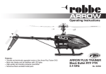
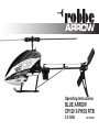
Operating Instructions
BLUE ARROW
CP120 S-FHSS RTB
2.4 GHz
No. S2540
Operating Instructions - BLUE ARROW CP120 S-FHSS RTB 2.4 GHz No. S2540
FUTABA Transmitter Ready, abbreviated to FTR, applies to products from the robbe range of fixed-wing
model
aircraft and helicopters fitted with receivers which process the FUTABA S-FHSS code, and can
therefore be bound to any FUTABA transmitter capable of being set to S-FHSS mode.
At present these are the following transmitters:
T6J-R2006GS 2.4 GHz FHSS, No. F4100
T-8J - R2008SB 2.4 GHz FHSS/S-FHSS, No. F4108
T18MZ - R7008SB 2.4 GHz FASSTest M2, No. F8073
T18MZ - R7008SB 2.4 GHz FASSTest M1, No. F8073M1
T-14SG-R7008SB 2.4 GHz FASSTest M2, No. F8075
T14SG-R7008SB 2.4 GHz FASSTest M1, No. F8075M1
FX-32-R7008 2.4 GHz FASSTest, No. F8078
robbe Modellsport GmbH & Co. KG hereby declares that this device conforms to the fundamental requirements and other relevant regulations of the corresponding EC Directive. You can read the original Conformity Declaration on the Internet at www.
robbe.com: click on the "Conformity Declaration" logo button which you will find next to the corresponding device description.
This symbol means that you should dispose of electrical and electronic equipment separately from the household waste when
it reaches the end of its useful life. Take your unwanted equipment to your local council collection point or recycling centre.
This requirement applies to member countries of the European Union as well as other non-European countries with a separate waste collection system.
Disposal of batteries
Batteries must not be discarded as domestic refuse. To protect the environment, always return exhausted or defective cells to
your local recycling centre. These include retail sales outlets for batteries, and communal toxic waste disposal centres. Cover
any bare wires with insulating tape in order to avoid short-circuits.
2
Operating Instructions - BLUE ARROW CP120 S-FHSS RTB 2.4 GHz No. S2540
Explanation of specialist terms:
Climb and descent ("Collective pitch / throttle"):
This controls the model's climb and descent.
Yaw: The model's movement around the vertical axis;
the helicopter rotates to right or left.
Elevator: The model's movement around the lateral
axis,
forward or reverse flight
Roll: The model's movement around the longitudinal
axis,
sideways movement to right or left
Binding: Creating the radio link between transmitter
and receiver.
Contents Conformity Declaration
Explanation of specialist terms / Contents
Safety Notes
Set contents / Specification / Recommended accessories
Safety Notes, LiPo batteries
Model description
Charging the flight battery
Receiver functions
Receiver settings
Preparing the transmitter, using a Futaba T8J RC system as an example
Installing the flight battery
Binding the transmitter to the model / trouble-shooting
Receiver adjustment facilities
Transmitter adjustment facilities
Pre-flight adjustments
Swashplate adjustments
Setting up the swashplate
Adjusting the main rotor blades / Self-adhesive marker stripes
Checking blade tracking
Adjusting blade tracking
Adjusting the tail rotor linkage
These points must be checked before flying / Important notes
Controlling the model in Mode 1 and Mode 2
Mechanical and electronic fine-tuning
Flight practice for the beginner
Practice for advanced pilots
Flying 3D aerobatics in Mode 1 and Mode 2
Replacement Parts list
Page
2
3
4, 5
6
7
8
8
9
10
10
10
11
12
12
13
13
13
14
14
14
15
16
17
18
19, 20
20, 21
22
23, 24
3
Operating Instructions - BLUE ARROW CP120 S-FHSS RTB 2.4 GHz No. S2540
Be sure to read these Safety Notes before you assemble your
model. Always keep to the procedures and settings recommended in the instructions.
Please bear in mind that motors and speed controllers
may become hot when operating. It is essential to avoid touching such parts.
If you are operating a radio-controlled model aircraft, helicopter, car or boat for the first time, we recommend that you
enlist an experienced modeller to help you.
Do not stand close to the hazard area around rotating parts
when an electric motor is connected to the flight battery.
You must also take care to keep all other objects away from
moving or rotating parts.
Safety Notes
Radio-controlled models are not toys in the usual sense of the
term. Young persons under fourteen years should only be allowed
to operate them under the supervision of an adult.
Building and operating these models requires technical expertise,
manual skills, a careful attitude and safety-conscious behaviour.
Errors, negligence and omissions in building or flying these models can result in serious personal injury and damage to property.
Since the manufacturer and vendor are not in a position to check
that your models are built and operated correctly, all we can do
is bring these hazards expressly to your attention. We deny all
further liability.
Helicopter rotors, and all moving parts generally, constitute a constant injury hazard. It is essential to avoid
touching such parts.
4
Observe the instructions provided by the battery manufacturer.
Overcharged or incorrectly charged batteries may explode.
Take care to maintain correct polarity.
Ensure the equipment is protected from dust, dirt and moisture
contamination. Do not subject the system to excessive heat, cold
or vibration.
Use the recommended charger only, and charge the batteries only
for the prescribed period.
Check your equipment for damage at regular intervals, and replace defective components with genuine spare parts.
Do not re-use any devices which have been damaged in a crash or
by water, even when they have dried out again.
Send the equipment to the robbe Service Department for checking, or replace the parts in question.
Crash or water damage can result in concealed defects which may
lead to failure in subsequent use.
Use only those components and accessories which we specifically
recommend.
Operating Instructions - BLUE ARROW CP120 S-FHSS RTB 2.4 GHz No. S2540
Do not carry out modifications to the radio control system components apart from those described in the instructions.
Operating the model
• Never fly over or towards spectators or other pilots, and
maintain a safe distance from them at all times.
• Never endanger people or animals.
• Never fly close to high-tension overhead cables or residential areas.
• Do not operate your model from public roads, motorways,
paths and squares etc.; use authorised model flying sites
only.
• Never operate your radio control system in stormy
weather.
Never “point” the transmitter aerial straight at the model when operating it. The transmitter signal is at its weakest in this direction.
It is always best to stand with the long side of the aerial angled
towards the model.
Insurance
Ground-based models are usually covered by standard personal
third-party insurance policies. In order to fly model aircraft you will
need to extend the cover of your existing policy, or take out specific
insurance.
Check your insurance policy (private third-party) and take out
new cover where necessary.
Liability exclusion:
robbe Modellsport is unable to ensure that you observe the assembly and operating instructions, or the conditions and methods used
for installing, operating and maintaining the model components.
For this reason we accept no liability for loss, damage or costs
which are due to the erroneous use and operation of our products,
or are connected with such operation in any way.
Regardless of the legal argument employed, our obligation to pay
compensation is limited to the invoice value of those robbe products directly involved in the event in which the damage occurred,
unless otherwise prescribed by law. This does not apply if the company is deemed to have unlimited liability according to statutory
regulation due to deliberate or gross negligence.
5
Operating Instructions - BLUE ARROW CP120 S-FHSS RTB 2.4 GHz No. S2540
Dear customer,
Congratulations on choosing a factory-assembled model helicopter from our range. Many thanks for placing
your trust in us.
The model can be completed and prepared for flight
very quickly. Please read right through these instructions before attempting to fly the model for the first
time, as this will make it much easier to operate the
model safely.
All directions, such as “right-hand”, are as seen from
the tail of the model, looking forward.
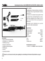
Set contents:
1 x Blue Arrow CP120 S-FHSS RTB
1 x LiPo battery, 3.7 V / 600 mAh, 20C
1 x USB battery charger
1 x Replacement rotor blades
1 x Replacement tail rotor gearbox
1 x Binding plug
1 x Tool set
1 x Operating instructions
Specification:
Main rotor diameter:
308 mm
Tail rotor diameter:
85 mm
Main drive motor: WK-WS-15-001
Length:
290 mm
All-up weight:
100 g
Gyro:six-axis
Servo:WK-02-1
Tail rotor servo:
WK-03-4
Recommended accessories:
1 x F4108 T-8J - R2008SB 2.4 GHz FHSS/S-FHSS
Please be sure to observe the safety notes regarding the safe handling of Lithium-Ion-Polymer batteries on page 7.
6
Operating Instructions - BLUE ARROW CP120 S-FHSS RTB 2.4 GHz No. S2540
Safety Notes regarding LiPo batteries:
• Do not place the battery in water or any other liquid.
• Never heat or incinerate the pack, or place it in a microwave oven.
• Avoid short-circuits, and never charge the battery with reversed polarity • Do not subject the battery to pressure or shock loads, and never distort or throw the pack.
• Never solder directly to the battery.
• Do not modify or open the battery.
• Batteries must only be charged with a suitable charger; never connect the battery directly to a mains power supply.
• Never charge or discharge a battery in bright sunlight, or close to a heater or open fire.
• Do not use the battery in areas subject to high levels of static electricity.
• Never leave the battery on charge unsupervised.
• Do not charge the battery in an inflammable location, or on an inflammable surface.
• Any of these errors can result in damage to the battery, explosion or fire.
• Keep the battery away from children.
• If electrolyte should escape, do not expose it to fire, as the material is highly inflammable and may ignite.
• Do not allow fluid electrolyte to come into contact with eyes. If this should happen, flush with copious amounts of water and
contact a doctor without delay.
• The fluid electrolyte can also be removed from clothing and other objects by rinsing with copious amounts of water.
LIABILITY EXCLUSION
Since robbe Modellsport is not in a position to monitor the handling of these batteries, we expressly deny all liability and guarantee
claims where the batteries have been incorrectly charged, discharged or handled.
7
Operating Instructions - BLUE ARROW CP120 S-FHSS RTB 2.4 GHz No. S2540
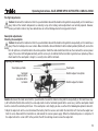
Model description:
1.Latest generation of six-axis gyro system with improved corrective response, ensuring stable, accurate flying.
2. The high-performance brushless motor provides ample power
for advanced 3D flying.
3.FUTABA S-FHSS receiving system for binding to all current
FUTABA S-FHSS transmitters.
4. Extremely robust overall chassis design.
5. This helicopter is capable of indoor flight times of around 8 to
9 minutes with a fully charged battery.
6.The ideal model for pilots who have experience flying collective-pitch helicopters, and wish to move up to 3D flying.
Please note the following points in order to avoid confusion
in the model description:
The model's nose faces away from the pilot; the tail boom points
towards the pilot. The pilot's left-hand side is the left-hand side of
the model, and the pilot's right-hand side is the right-hand side of
the model. The rotor head faces up, and the landing skids face
down (see illustration).
top
right
front
rear
bottom
8
left
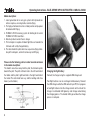
Charging the flight battery
Connect the charger using the supplied USB charge lead.
Two flight batteries can be recharged simultaneously. Connect
the USB charge lead to the USB socket of your PC, then plug one
or two flight batteries into the charge sockets on the side of the
charger. A red monitor LED glows by each charge socket during
the charging process. The monitor LEDs go out when the charge
process is complete.
Operating Instructions - BLUE ARROW CP120 S-FHSS RTB 2.4 GHz No. S2540
10
11
1
2
3
4
5
6
9
8
7
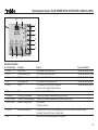
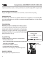
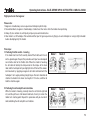
Receiver functions:
No.
1
2
3
4
5
Brief description
RUDD
ELEV
AILE
PIT
THRO
6 AUX
7 RUDD EXT.
8 ELEV / AILE EXT.
9 ELEV / AILE G.
Description
Tail rotor servo
Pitch-axis (elevator) servo
Roll servo
Collective pitch servo
Throttle
AUX
Tail rotor servo travel adjuster
Pitch-axis / roll servo travel adjuster
Adjusters for head gyro gain.
10 ADJ - WK
Flight mode switch (switch 2)
11 LED
LED
Function
Connector orientation
To be connected to the tail rotor servo
The white wire must face forward
To be connected to the pitch-axis servo
The white wire must face forward
To be connected to the roll servo
The white wire must face forward
To be connected to the collective pitch servo
The white wire must face forward
To be connected to the speed controller's signal wire;
The white wire must face forward
receives the control signals for the main drive motor
To be connected to the FHSS module
This pot is used to adjust the maximum travel of the tail rotor servo
This pot is used to adjust the maximum travel of the pitch-axis and roll servos
Gyro gain adjuster
for the pitch and roll axes
The switch must be moved to the ADJ (adjustment) position once in order to adjust the mechanical system.
Selecting ADJ mode sets all the servos to neutral (centre)
Indicates receiver status during binding and receive operations
9
Operating Instructions - BLUE ARROW CP120 S-FHSS RTB 2.4 GHz No. S2540
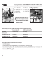
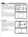
W
A
C
D
E
F
G
A = BL motor socket
B = S-FHSS module servo
C = Binding button
D = Pitch-axis servo
E = Roll servo
Installing the flight battery:
F = Collective pitch
G = Tail rotor servo
Disconnect the brushless motor connector before binding the transmitter
and before making any other adjustments on the model.
Receiver settings (large case), S-FHSS module settings (small circuit board on the receiver):
Receiver status LED
S-FHSS module status LED
No reception/
Very fast flashing
Fast flashing
Binding required
Initialising transmitter signal
Fast flashing
Continuous light
Receiving transmitter signal
Continuous light
Continuous light
Preparing the transmitter, using the Futaba T8J as an example:
- Set S-FHSS modulation
- The transmitter must be set to swashplate mode H-1 (see T8J instructions, 8.1 Parameter, page 38)
- Reverse the roll (CH1), pitch-axis (CH2), throttle (CH3), tail rotor (CH4) and collective pitch (CH6) channels (see T8J instructions, 7.10
Servo reverse (SERVO REV), page 20)
10
Operating Instructions - BLUE ARROW CP120 S-FHSS RTB 2.4 GHz No. S2540
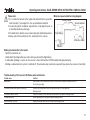
Please note:
1.It is essential to connect all the signal leads attached to the speed controller correctly. If you neglect this, the speed controller could fail.
2.Use only the plastic screwdriver supplied in the set to adjust the pots, as
a metal tool could cause damage.
3.The model must stand on a level surface during the initialisation process.
4.Always switch the transmitter on first, and only then the receiver.
Motor and speed controller wiring diagram:
Battery socket
Speed controller
Flight battery
Main drive motor
Receiver
Binding the transmitter to the model:
- Switch the transmitter on
- Hold button D (binding button) pressed in while you connect the flight battery
- If initialisation (binding) is successful, the receiver's status LED and the S-FHSS module LED glow constantly
- Binding is retained when the system is switched off. The procedure only needs to be repeated if you replace the receiver or transmitter
Trouble-shooting if the receiver LED flashes when switched on:
Possible causes
Binding failed
The throttle stick and throttle trim are set incorrectly
The transmitter batteries are flat
The flight battery is flat
Fault in transmitter or receiver
Solutions
Switch the radio control transmitter and receiver off. Now switch the transmitter on again, and connect
the receiver power supply.
Set the throttle stick and throttle trim to the lowest position (motor off), and repeat the
binding procedure.
Replace the flat batteries in the transmitter with new batteries, and repeat the binding procedure.
Give the flight battery a full charge, and repeat the binding procedure.
Replace the faulty unit with a new one, and repeat the binding procedure.
11
Operating Instructions - BLUE ARROW CP120 S-FHSS RTB 2.4 GHz No. S2540
Receiver adjustment facilities:
1.Gyro pot: ELEV / AILE G. 2.Servo travel adjuster: ELEV / AILE EXT. and RUDD EXT.
Turning the pot clockwise (+) increases gyro gain;
Turning the pot anti-clockwise (-) reduces gyro gain.
Turning the pot clockwise (+) increases servo travel;
Turning the pot anti-clockwise (-) reduces servo travel.
Transmitter adjustment facilities:
Adjusting the throttle curve:
- To program the throttle curves, please follow the description in the instructions supplied
with your T8J radio control system (8.2 Programming the throttle curve (THR CURVE),
page 40).
Flight mode Normal 3D flying 1 3D flying 2 L
Output
0.0% 100.0% 100.0% M
H
50.0%
75.0% 75.0% 100.0%
100.0%
100.0%
Adjusting the collective pitch curve:
- To program the collective pitch curves please follow the description in the instructions supplied with your T8J radio control systems (8.9 Setting collective pitch travel (COLL TRAVEL), page 47)
Flight mode Normal 3D flying 1 3D flying 2 L
Output
-20% -56% -56% M
H
+20%
+0% +0% +56%
+56%
+56%
Adjusting tail rotor gyro gain:
- To adjust the gain of the tail rotor gyro please follow the description in the instructions supplied with your T8J radio control system (8.5 Gyro (gyro gain), page 44)
ModeManual
Switch MIX SW
Pos. 0 80.0% Pos. 1 75.0% Pos. 2 50.0% 12
Operating Instructions - BLUE ARROW CP120 S-FHSS RTB 2.4 GHz No. S2540
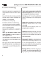
Pre-flight adjustments:
Caution: disconnect the motor wires from the speed controller to avoid the motor bursting into life unexpectedly, as this could cause
injury. Note: all the model's components are correctly set up at the factory, and no adjustments are normally required. However,
screws, pushrods or cables may have worked loose or suffered damage due to the long period in transit.
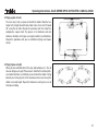
Swashplate adjustments:
Checking the swashplate
Caution: disconnect the motor wires from the speed controller to avoid the motor bursting into life unexpectedly, as this could cause
injury. Place the helicopter on a level surface. Move the throttle stick and throttle trim to the bottom position (throttle off), and set the
trims for pitch-axis, roll and tail rotor to the centre position. Switch the radio control transmitter on, then connect the receiver power
supply. The receiver LED will glow constantly, and the servos jerk, to indicate that the transmitter signal has been picked up. Please
check now that the swashplate is straight, i.e. exactly in line with the tail boom.
Adjusting the swashplate
Swashplate pushrods
horizontal
alignment of the
swashplate to the
tail boom
Swashplate
Bottom edge of swashplate
Bottom edge of tail boom
Caution: disconnect the motor wires from the speed controller to avoid the motor bursting into life unexpectedly, as this could cause injury. At half-throttle (throttle stick central) the servo output arms must be horizontal (parallel to the servo case), and the swashplate should
be in the centre of the collective pitch travel. If the swashplate is not straight, you can use either of the following two options to correct it.
1.Adjust the output arm on the servo: disconnect the battery from the receiver, and switch the transmitter off. Unscrew the output lever
from the servo. Now switch the transmitter on, and connect the receiver power supply. When the initialisation process is complete, fit
the output arm on the servo at 90° to the pushrod, then fit the retaining screw to secure the output arm.
13
Operating Instructions - BLUE ARROW CP120 S-FHSS RTB 2.4 GHz No. S2540
2.Adjust the mechanical linkage: lengthen or shorten the pushrod between the servo and the swashplate until the swashplate is straight.
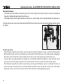
Adjusting the main rotor blades (blade tracking):
The purpose of this adjustment is to avoid imbalance in the main rotor blades, and to set the blade tracking accurately.
Self-adhesive marker stripes
Two self-adhesive stripes of different colour are applied to the rotor blades in order to simplify the adjustment of blade tracking. When
the main rotor is spinning, you can check which blade has to be adjusted by observing the coloured stripes, i.e. the blade to which an
adjustment needs to be made.
Checking blade tracking:
Please note: to avoid accidents it is important to place the model at least three metres from you when checking blade tracking. Slowly advance the throttle (don't allow
the model to take off), and observe the rotor plane from the side. If the outside edges
of both rotor blades are exactly in line when the rotor is spinning, the blade tracking is
correct. However, if you can detect two lines, you must correct the blade tracking by
adjusting the pushrods at the blade grips.
Adjusting blade tracking
The following section describes the main causes for incorrect blade tracking:
1. The blades are of different weight.
Remedy: remove the adhesive tape from the heavier blade, or apply more tape to
the lighter blade to increase its weight.
2. The Centre of Gravity of the blades is not identical.
3. The length of the rotor blade pushrods is not identical.
4. The blades are not secured firmly enough, allowing the blade grips to distort.
Adjusting the tail rotor linkage:
This step is only necessary if you replace the tail rotor servo.
14
Correct blade tracking
Incorrect blade tracking
Pushrods
Main rotor blades
Operating Instructions - BLUE ARROW CP120 S-FHSS RTB 2.4 GHz No. S2540
Move the throttle stick and trim to their lowest position, and move the tail rotor stick to the neutral position. When you have installed the
new tail rotor servo, check that the tail slider sleeve is central on the tail rotor shaft, and that the servo output arm is at 90° to the servo
case and the tail rotor pushrod. If everything is as stated, it is safe to fly the model. However, if there is a problem, switch the helicopter
off and then on again. When initialisation is complete, the tail rotor servo will again be at the neutral position. Fit the servo output arm at
an angle of 90° to the servo, then lengthen or shorten the tail rotor pushrod until the tail rotor slider sleeve is central on the tail rotor shaft.
Setting the flight mode (ADJ – WK switch):
Note: mount the receiver lying flat in the model, at right-angles to the main rotor shaft.
1.Adjustment mode (ADJ):
First bind your transmitter to the model, then move the flight mode switch on the receiver (switch 2) to the ADJ position. The receiver
and helicopter are now in set-up mode. The purpose of this mode is to adjust the servo output arms and the swashplate linkages. When
adjustments are complete, be sure to move the switch back to WK, as it is not possible to fly the model in ADJ mode.
2.Stabilised flying:
Return the flight mode switch on the receiver (switch 2) to the WK position. In this mode the two swashplate servos of a flybarless helicopter are stabilised in addition to the tail rotor. First set the travel adjuster (potentiometer) for pitch-axis and roll (ELEV / AILE EXT.)
and the gyro gain adjuster for pitch-axis and roll (ELEV AILE G.) to 50%, and then adjust the two pots to suit your personal preference
during a series of test-flights. Increase gyro gain until the model jitters slightly around the pitch and roll axes, then reduce the gain slowly
until the jittering ceases again. Increasing the servo travels makes the model more agile; reducing servo travel makes the model less
responsive.
15
Operating Instructions - BLUE ARROW CP120 S-FHSS RTB 2.4 GHz No. S2540
These points must be checked before flying:
Important notes:
- Before flying the model check that the receiver battery is fully
charged, and that the transmitter batteries still have adequate
capacity.
- Ensure that the throttle stick is at the lowest position (fully
back) before switching the model on, and that all other sticks
and switches are in the normal position.
- Check that all servos are working perfectly.
- Check that each component has been installed correctly.
- Check that the whole model is in perfect technical condition.
- When it is time to switch the receiver and transmitter on or off,
please observe the following procedure:
- Always switch the transmitter on first, and only then the
receiver.
- After the flight always switch the receiver off first, and
only then the transmitter. If you neglect this sequence, the
model could fly off out of control.
- Check that all linkages are correctly fitted and devoid of lost
motion; replace them if necessary. Sloppy linkages may cause
instability in flight.
- Before flying the model, check that the electrical connection
between flight battery and model is secure. Vibration can cause loose connectors to come adrift in flight, rendering the model uncontrollable.
Take-off: raise the rotor speed slowly and steadily until the
model hovers at eye-level. At the same time adjust the trims
until the helicopter flies stably and hovers over one point.
At low height (approx. 10 - 15 cm above the ground) the model
cannot be trimmed accurately due to the turbulence generated
by the rotor.
16
Landing: slowly and steadily reduce the throttle setting until the
model descends and touches down. Never reduce the throttle
setting abruptly.
After the landing disconnect the flight battery from the receiver,
and only then switch the transmitter off.
Caution: Stopping (obstructing) the rotor blades when they are
turning can cause serious damage to the mechanical system,
and may even result in a fire. Immediately move the throttle stick
to Idle if this should happen.
Note regarding the flight battery: as soon as you notice a reduction in motor power, land immediately and disconnect the battery. Never continue flying until the battery is flat, as this causes
a deep-discharge condition which results in permanent damage.
Allow the battery to cool down before recharging it.
Replacing the rotor blades: if a rotor blade is damaged, replace
it immediately. When fitting the new rotor blade, tighten the retaining screw just to the point where the blade still swivels smoothly.
Operating Instructions - BLUE ARROW CP120 S-FHSS RTB 2.4 GHz No. S2540
Controlling the model in Mode 1 (throttle right)
Controlling the model in Mode 2 (throttle left)
Roll:
If you move the roll stick
to left or right, the helicopter flies in the corresponding direction.
Roll:
If you move the roll stick
to left or right, the helicopter flies in the corresponding direction.
Climb / descent:
When you move the
throttle stick up or down,
the helicopter climbs or
descends.
Climb / descent:
When you move the
throttle stick up or down,
the helicopter climbs or
descends.
Yaw:
If you move the tail rotor
stick to left or right, the
helicopter rotates in the
corresponding direction.
Yaw:
If you move the tail rotor
stick to left or right, the
helicopter rotates in the
corresponding direction.
Pitch-axis:
If you move the pitch-axis
stick up or down, the helicopter will fly forward or
back.
Pitch-axis:
If you move the pitch-axis
stick up or down, the helicopter will fly forward or
back.
17
Operating Instructions - BLUE ARROW CP120 S-FHSS RTB 2.4 GHz No. S2540
Mechanical fine-tuning:
- If the model drifts in one direction when hovering, either in the roll (left / right) or pitch (forward / back) axis, adjust the swashplate by
shortening / lengthening the pushrods until the drift ceases.
- If the helicopter swings to left or right around the vertical (yaw) axis, adjust the length of the tail rotor pushrod until the yawing ceases.
The travel of the tail rotor servo can be limited using the RUDD EXT pot. Ensure that the slider sleeve on the tail rotor shaft does not foul
the housing.
Electronic fine-tuning:
- If the model jitters around the roll or pitch axis when hovering, then the gain of the flybarless system is set too high. Turn the ELEV /
AILE G pot (for the pitch and roll axis) anti-clockwise in small increments until the jitter ceases. If the model responds lethargically to
the controls, turn this pot clockwise until the helicopter starts to jitter, then turn it anti-clockwise again until the jitter ceases.
- If you wish to increase agility around the roll and pitch axes, turn the ELEV / AILE EXT pot clockwise in small increments until the
preferred level of manoeuvrability is obtained. Turn the pot anti-clockwise if you wish to reduce the model's control response.
- If the model jitters around the roll or pitch axis when hovering, then the gain of the flybarless system is set too high. If the tail is not
stable, and swings in one direction when a sudden collective pitch command is given, then gyro gain is too low. If you need to adjust
tail gyro gain, please use the Gyro menu of your T8J transmitter (Instructions: 8.5 Gyro (gyro gain), page 44).
18
Operating Instructions - BLUE ARROW CP120 S-FHSS RTB 2.4 GHz No. S2540
Flight practice for the beginner
Please note:
1.Beginners should always ask an experienced helicopter pilot for help.
2.To avoid accidents, beginners should always stand at least five metres from the model when practising.
3.Always fly at a suitable site, with plenty of open space and no obstacles.
4.Your model is a 3D helicopter. We recommend that you first gain experience by flying a co-axial helicopter or using a flight simulator
before attempting to fly this model.
First steps:
1.Practising throttle control – hovering
If the model starts to lift off, carefully back off the throttle until it rests
on the ground again. Repeat this procedure until you have developed
an instinctive feel for the throttle stick. When the model is hovering,
the tail rotor will attempt to compensate for the torque of the main
rotor, and the helicopter will yaw slightly to the left. Correct this unwanted movement by applying an opposite tail rotor command until the
helicopter's tail is again pointing straight at you. Your aim should be to
stabilise the model in the hover at a height of 1.5 metres, and then to
land the machine again.
2.Practising the roll and pitch-axis functions
While the model is hovering, carefully move the roll stick to right and
left, and the pitch-axis stick forward and back, then try to return the
model to its starting point. Repeat this procedure until you feel confident controlling the roll and pitch-axis functions.
Mode 1
Mode 2
Mode 1
Mode 2
19
Operating Instructions - BLUE ARROW CP120 S-FHSS RTB 2.4 GHz No. S2540
3.Practising the tail rotor function
While the model is hovering, carefully move the tail rotor stick to left
and right. The helicopter will yaw in the corresponding direction, and
you should then use the same stick to return it to its original heading.
Repeat this procedure until you feel confident controlling the tail rotor
function.
4.Flying circuits
When you feel confident with steps (1) – (3), it is time to move on to
the first circuits. Please bear in mind that the roll and pitch-axis control
functions are effectively reversed when the model is flying towards
you. Repeat this manoeuvre until you are confident flying a circular
pattern.
Practice for advanced pilots:
1."Frog-hopping" practice
Allow the helicopter to take off briefly, then land it again immediately, using the throttle stick. It is a good idea to repeat this procedure,
gradually gaining speed, and this will help you gain confidence and a
feeling for the model's flying characteristics. Take care to flare out in
good time before the model touches down each time, otherwise the
landings could cause damage.
2.Practising take-off and landing
Mark a point on the ground, and try to take off and land on this point
every time.
20
Mode 1
Mode 2
Operating Instructions - BLUE ARROW CP120 S-FHSS RTB 2.4 GHz No. S2540
3.Flying square circuits
The next step is to fly a square circuit with the model. Allow the helicopter to fly straight ahead for about two metres, then turn it through
90° using the tail rotor. Repeat this procedure until the model has
completed a square circuit. Fly squares in the clockwise and anticlockwise direction, so that you are using the controls in all directions.
Repeat the procedure until you are confident at flying neat square
circuits.
4.Flying figures-of-eight
When you feel confident with all the steps outlined above, it is time to
move on to figures-of-eight. Please bear in mind that the roll and pitchaxis control functions are effectively reversed when the model is flying
towards you. During all parts of the manoeuvre take care to keep the
model at a steady height. Repeat the manoeuvre until you are sure of
what you are doing.
21
Operating Instructions - BLUE ARROW CP120 S-FHSS RTB 2.4 GHz No. S2540
3D flying in Mode 1 (throttle right)
22
3D flying in Mode 2 (throttle left)
When you move the roll
stick to left or right, the
helicopter moves in the
corresponding direction.
The control 'sense' remains normal.
When you move the roll
stick to left or right, the
helicopter moves in the
corresponding direction.
The control 'sense' remains normal.
When you move the
throttle stick up or down,
the helicopter climbs or
descends. The control
'sense' is reversed.
When you move the
throttle stick up or down,
the helicopter climbs or
descends. The control
'sense' is reversed.
When you move the tail
rotor stick to left or right,
the helicopter rotates
(yaws) in the corresponding direction around the
vertical axis. The control
'sense' is reversed.
When you move the tail
rotor stick to left or right,
the helicopter rotates
(yaws) in the corresponding direction around the
vertical axis. The control
'sense' is reversed.
When you move the pitchaxis stick up or down, the
helicopter flies forward or
back. The control 'sense'
is reversed.
When you move the pitchaxis stick up or down, the
helicopter flies forward or
back. The control ‚sense‘
is reversed.
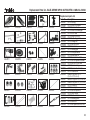
Replacement Parts list - BLUE ARROW CP120 S-FHSS RTB 2.4 GHz No. S2540
Replacement parts list
S2540001
S2540002
S2540003
S2540004
S2540005
S2540006
S2540007
S2540008
S2540009
S2540010
S2540011
S2540012
S2540013
S2540014
S2540015
S2540016
S2540017
S2540018
S2540019
S2540020
S2540021
S2540022
S2540023
S2540024
S2540025
S2540026
S2540027
S2540028
S2540029
S2540030
Order No.
S2540001
S2540002
S2540003
S2540004
S2540005
S2540006
S2540007
S2540008
S2540009
S2540010
S2540011
S2540012
S2540013
S2540014
S2540015
S2540016
S2540017
S2540018
S2540019
S2540020
S2540021
S2540022
S2540023
S2540024
S2540025
S2540026
S2540027
S2540028
S2540029
S2540030
Description
CP120 canopy
CP120 main rotor blades
CP120 tail rotor blades
CP120 main rotor blade grip
CP120 rotor head
CP120 main rotor shaft
CP120 feathering spindle
CP120 linkage set
CP120 tail rotor shaft
CP120 main frame
CP120 landing gear
CP120 main gearwheel
CP120 bevel gear set
CP120 tail rotor drive shaft
CP120 tail rotor gearbox bracket
CP120 tail rotor control arm
CP120 tail rotor linkage
CP120 tail rotor blade holder
CP120 stabiliser set
Ballrace set, pack of 4 + 2
(2 x 5 x 2 / 1.5 x 4 x 2)
Ballrace set, pack of 2 (2.5 x 6 x 2.5)
Ballrace set, pack of 2 (1.5 x 4 x 2)
CP120 screw set
CP120 swashplate
CP120 tail rotor pushrod
CP120 servo mount
CP120 tail boom brace
CP120 retaining piece
CP120 tail boom
CP120 BL speed controller, 20 A
23
Replacement Parts list - BLUE ARROW CP120 S-FHSS RTB 2.4 GHz No. S2540
Replacement parts list
S2540031
S2540032
S2540033
S2540036
S2540037
S2540038
S2540034
S2540035
When replacing components it is very important to use the correct type of cross-point screwdriver and
to tighten the screws with great care. Do not use thread-lock fluid!
Order No. Description
S2540031
CP120 BL motor 15-001
S2540032
LiPo battery, 3.7 V / 600 mAh
S2540033
CP120 swashplate servo
S2540034
CP120 tail rotor servo
S2540035
CP120 S-FHSS receiver
S2540036
CP120 metal rotor blade grip
(upgrade)
S2540037
CP120 metal rotor head
(upgrade)
S2540038
CP120 metal swashplate
(upgrade)
S2540039
Main rotor head, complete set Metal (not shown)
robbe Modellsport GmbH & Co.KG
Metzloserstraße 38 · D-36355 Grebenhain
Technical hotline: +49 (0)66 44 / 87-777 · [email protected]
Commercial register: Gießen Regional Court HRA 2722
Partner with personal liability:
robbe Modellsport Beteiligungs GmbH Gießen / HRB 5793 · Managing Director: E. Dörr
Errors and technical modifications reserved. - Copyright robbe-Modellsport 2013
Duplication and copying of the text, in whole or in part, is only permitted with the prior written approval of robbe-Modellsport GmbH & Co. KG
24