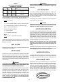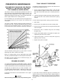
1
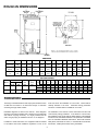
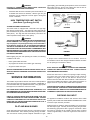
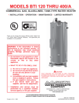
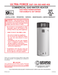
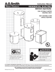
MODELS BT- 80 AND 100
COMMERCIAL GAS WATER HEATER
Glass-Lined Tank-Type Water Heater
• INSTALLATION • OPERATION • SERVICE • MAINTENANCE • LIMITED WARRANTY
Thank you for buying this energy efficient water heater from
A.O. Smith Water Products Company. We appreciate your
confidence in our products.
CAUTION
TEXT IN BLACK BOLD TYPE OR UNDERLINED
CONTAINS INFORMATION RELATIVE TO YOUR
SAFETY. PLEASE READ THOROUGHLY BEFORE
INSTALLING AND USING THIS APPLIANCE.
A DIVISION OF A.O. SMITH CORPORATION
McBEE, SOUTH CAROLINA, USA
www.aosmithwaterheaters.com
PRINTED IN U.S.A. 1004
PLACE THESE INSTRUCTIONS ADJACENT TO HEATER
AND NOTIFY OWNER TO KEEP FOR FUTURE REFERENCE.
1
PART NO. 196158-001
ROUGH-IN DIMENSIONS
FIGURE 1.
DIMENSIONS
Model
Units
A
B
C
D
E
F
G
H
J
K
L
M
BT-80
Natural & LP
Inches
CM
61 1/8
155.25
58 1/2
148.6
29 11/16
75.4
26 1/2
67.3
15 3/16
38.6
4
10.2
14 1/2
39.4
16
40.6
1 1/4
3.2
1
NPT
1/2
NPT
11 15/16
30.3
BT-100
Natural
Inches
CM
69 3/4
177.2
66 1/2
168.9
29 11/16
75.4
26 1/2
67.3
15 3/16
38.6
4
10.2
14 1/2
39.4
16
40.6
1 1/4
3.2
1 1/4
NPT
1/2
NPT
11 15/16
30.3
BT-100
LP
Inches
CM
68 5/8
174.3
66 1/2
168.9
30 15/16
78.59
27 3/4
70.5
15 3/16
38.6
4
10.2
15 3/4
40.0
16
40.6
1 1/4
3.2
1 1/4
NPT
1/2
NPT
11 15/16
30.3
44
80
91
343
91
343
50
90
81
305
81
305
RECOVERY RATINGS
BT- 80
Input
Rating Rating
Btu/Hr
kW
75,100
22.0
BT -100
75,100
Model
22.0
Approx.
Gal.
Cap.
74
98
Approx.
Liter
Temp. C°
Cap.
Rise F°
280
GPH
LPH
371
GPH
LPH
17
30
243
916
243
916
22
40
182
686
182
686
28
50
146
550
146
550
33
60
121
456
121
456
39
70
104
392
104
392
56
100
73
275
73
275
61
110
66
249
66
249
67
120
61
230
61
230
72
130
56
211
56
211
78
140
52
196
52
196
Recovery ratings based on 80% thermal efficiency.
FOREWORD
The design of models BT-80 and 100 comply with the latest version
of ANSI Z21.10.3-CSA 4.3 as automatic storage or automatic
circulating tank type water heaters.
local area where the installation is to be made. These shall be
carefully followed in all cases. Authorities having jurisdiction
should be consulted before installations are made.
Installation diagrams are found in this manual. These diagrams
will serve to provide the installer with a reference for the materials
and method of piping necessary. It is highly essential that all
water and gas piping be installed as shown on the diagrams.
The installation must conform to these instructions and the local
code authority having jurisdiction. In the absence of local codes,
the installation must comply with the latest editions of the National
Fuel Gas Code, ANSI Z223.1/NFPA 54. This publication is available
from the Canadian Standards Association, 8501 East Pleasant
Valley Road, Cleveland, OH 44131, or the National Fire Protection
Association, 1 Batterymarch Park, Quincy, MA 02269.
In addition to these instructions, the equipment shall be installed
in accordance with those installation regulations in force in the
2
TABLE OF CONTENTS
ROUGH-IN DIMENSIONS .......................................................................
FOREWORD ..........................................................................................
GENERAL SAFETY INFORMATION ......................................................
Precautions .......................................................................................
Chemical Vapor Corrosion ...............................................................
Improper Combustion ........................................................................
Liquid Petroleum Models ...................................................................
Extended Non-use Periods ..............................................................
Insulation Blankets ............................................................................
Circulating Pump ...............................................................................
INSTALLATION INSTRUCTIONS ............................................................
Required Ability .................................................................................
Locating The Heater .........................................................................
High Altitude Installations ..................................................................
Clearances .......................................................................................
Hard Water .......................................................................................
Air Requirements ..............................................................................
Water (Potable) Heating and Space Heating ...................................
Venting ..............................................................................................
Thermometers (Not Supplied) ..........................................................
Relief Valve .......................................................................................
Gas Piping .........................................................................................
Gas Pressure Regulator ..................................................................
Page
2
2
3-4
3
3
3
3-4
4
4
4
4-9
4
4-5
5
5
5
5-6
6
6-7
7
7
8-9
9
Page
OPERATION .......................................................................................... 9-13
To Operate The Water Heater ......................................................... 9
Purging ............................................................................................. 9
Lighting Instructions ........................................................................ 10-11
Temperature Regulation .................................................................. 12
Check Venting ................................................................................. 12-13
High Temperature Limit Switch ........................................................ 13
SERVICE INFORMATION ...................................................................... 13-14
Pilot and Main Burner ....................................................................... 13
Checking Gas Input ......................................................................... 13-14
Vent System .................................................................................... 14
Relief Valve ...................................................................................... 14
Hot Water Odor ............................................................................... 14
Anode Rod Inspection ..................................................................... 14
Winter Protection ............................................................................. 14
Replacement Parts .......................................................................... 14
PREVENTIVE MAINTENANCE .............................................................. 15-16
Recommended Procedure For Periodic Removal Of Lime
Deposits From Tank Type Commercial Water Heaters ................... 15
Deliming Solvents ............................................................................ 15
Tank Cleanout Procedure ................................................................ 15-16
CHECKLIST .......................................................................................... 16-17
LIMITED WARRANTY ............................................................................ 18
IMPROPER COMBUSTION
GENERAL SAFETY
INFORMATION
WARNING
ATTIC AND/OR EXHAUST FANS OPERATING ON THE PREMISES
WITH A WATER HEATER CAN RESULT IN CARBON MONOXIDE
POISONING AND DEATH.
PRECAUTIONS
DO NOT USE THIS APPLIANCE IF ANY PART HAS BEEN UNDER
WATER. Immediately call a qualified service technician to inspect
the appliance and to replace any part of the control system and any
gas control which has been under water.
OPERATION OF THESE FANS CAN PRODUCE A NEGATIVE DRAFT
IN THE AREA OF THE WATER HEATER PREVENTING THE
PRODUCTS OF COMBUSTION FROM EXHAUSTING THROUGH
THE CHIMNEY OR VENT PIPE.
IF THE UNIT IS EXPOSED TO THE FOLLOWING, DO NOT
OPERATE HEATER UNTIL ALL CORRECTIVE STEPS HAVE BEEN
MADE BY A QUALIFIED SERVICEMAN.
The venting of the water heater should be inspected by a qualified
service technician at the time of installation and periodically
thereafter to ensure a down-draft condition does not exist.
1. EXTERNAL FIRE.
DO NOT OBSTRUCT THE FLOW OF COMBUSTION AND
VENTILATING AIR. ADEQUATE AIR FOR COMBUSTION AND
VENTILATION MUST BE PROVIDED FOR SAFE OPERATION.
2. DAMAGE.
3. FIRING WITHOUT WATER.
LIQUID PETROLEUM MODELS
4. SOOTING
Water heaters for propane or liquefied petroleum gas (LPG) are
different from natural gas models. A natural gas heater will not
function safely on LP gas and no attempt should be made to
convert a heater from natural gas to LP gas.
CHEMICAL VAPOR CORROSION
WARNING
CORROSION OF THE FLUEWAYS AND VENT SYSTEM MAY OCCUR
IF AIR FOR COMBUSTION CONTAINS CERTAIN CHEMICAL VAPORS.
SUCH CORROSION MAY RESULT IN FAILURE AND RISK OF
ASPHYXIATION.
LP gas must be used with great caution. It is highly explosive
and heavier than air. It collects first in the low areas making its
odor difficult to detect at nose level. If LP gas is present or even
suspected, do not attempt to find the cause yourself. Go to a
neighbor's house, leaving your doors open to ventilate the house,
then call your gas supplier or service agent. Keep area clear
until a service call has been made.
Spray can propellants, cleaning solvents, refrigerator and air
conditioning refrigerants, swimming pool chemicals, calcium and
sodium chloride (water softener salt), waxes, and process
chemicals are typical compounds which are potentially corrosive.
Do not store products of this sort near the heater. Also, air which is
brought in contact with the heater should not contain any of these
chemicals. If necessary, uncontaminated air should be obtained
from remote or outside sources. The limited warranty is voided
when failure of water heater is due to a corrosive atmosphere.
(Refer to the limited warranty for complete terms and conditions.)
At times you may not be able to smell an LP gas leak. One cause
is odor fade, which is a loss of the chemical odorant that gives
LP gas its distinctive smell. Another cause can be your physical
condition, such as having a cold or diminishing sense of smell
with age. For these reasons, the use of a propane gas detector
is recommended.
3
IF YOU EXPERIENCE AN OUT-OF-GAS SITUATION, DO NOT TRY TO
RELIGHT APPLIANCES YOURSELF, ask your LP delivery person to
relight pilots for you. Only trained LP professionals should conduct
the required safety checks in accordance with industry standards.
INSTALLATION INSTRUCTIONS
EXTENDED NON-USE PERIODS
INSTALLATION OR SERVICE OF THIS WATER HEATER REQUIRES
ABILITY EQUIVALENT TO THAT OF A LICENSED TRADESMAN IN
THE FIELD INVOLVED. PLUMBING, AIR SUPPLY, VENTING AND
GAS SUPPLY WORK ARE REQUIRED.
REQUIRED ABILITY
WARNING
HYDROGEN GAS CAN BE PRODUCED IN A HOT WATER SYSTEM
SERVED BY THIS HEATER THAT HAS NOT BEEN USED FOR A LONG
PERIOD OF TIME (GENERALLY TWO WEEKS OR MORE).
HYDROGEN GAS IS EXTREMELY FLAMMABLE. To reduce the risk
of injury under these conditions, it is recommended that the hot
water faucet be opened for several minutes at the kitchen sink
before using any electrical appliance connected to the hot water
system. If hydrogen is present, there will probably be an unusual
sound such as air escaping through the pipe as the water begins
to flow. THERE SHOULD BE NO SMOKING OR OPEN FLAME NEAR
THE FAUCET AT THE TIME IT IS OPEN.
GENERAL
The heater is designed to operate on natural or propane gases.
HOWEVER, MAKE SURE the gas on which the heater will operate
is the same as that specified on the heater model and rating plate.
LOCATING THE HEATER
When installing the heater, consideration must be given to proper
location. Location selected should be as close to the stack or
chimney as practicable, with adequate air supply and as
centralized with the piping system as possible.
INSULATION BLANKETS
WARNING
THERE IS A RISK IN USING FUEL BURNING APPLIANCES SUCH AS
GAS WATER HEATERS IN ROOMS, GARAGES OR OTHER AREAS
WHERE GASOLINE, OTHER FLAMMABLE LIQUIDS OR ENGINE
DRIVEN EQUIPMENT OR VEHICLES ARE STORED, OPERATED OR
REPAIRED. FLAMMABLE VAPORS ARE HEAVY AND TRAVEL
ALONG THE FLOOR AND MAY BE IGNITED BY THE HEATER’S PILOT
OR MAIN BURNER FLAMES CAUSING FIRE OR EXPLOSION. SOME
LOCAL CODES PERMIT OPERATION OF GAS APPLIANCES IF
INSTALLED 18" (46CM) OR MORE ABOVE THE FLOOR. THIS MAY
REDUCE THE RISK IF LOCATION IN SUCH AN AREA CANNOT BE
AVOIDED.
Insulation blankets available to the general public for external use
on gas water heaters are not approved for use on your A.O. Smith
water heater. The purpose of an insulation blanket is to reduce
the standby heat loss encountered with storage tank water
heaters. Your A.O. Smith water heater meets or exceeds the
ASHRAE/IES 90.1b-1999 standards with respect to insulation and
standby loss requirement making an insulation blanket
unnecessary.
WARNING
Should you choose to apply an insulation blanket to this heater,
you should follow these instructions. Failure to follow these
instructions can result in fire, asphyxiation , serious personal
injury or death.
•
Do not apply insulation to the top of the water heater, as this
will interfere with safe operation of the draft hood.
•
Do not cover the outer door, thermostat or temperature &
pressure relief valve.
•
Do not allow insulation to come within 2" (5cm) of the floor to
prevent blockage of combustion air flow to the burner.
•
Do not cover the instruction manual. Keep it on the side of
the water heater or nearby for future reference.
•
Do obtain new warning and instruction labels from A.O. Smith
for placement on the blanket directly over the existing labels.
•
Do inspect the insulation blanket frequently to make certain
it does not sag, thereby obstructing combustion air flow.
DO NOT INSTALL THIS WATER HEATER DIRECTLY ON A
CARPETED FLOOR. A FIRE HAZARD MAY RESULT. Instead the
water heater must be placed on a metal or wood panel extending
beyond the full width and depth by at least 3" (76.2mm) in any
direction. If the heater is installed in a carpeted alcove or closet,
the entire floor shall be covered by the panel. Also, see the drain
requirements.
THIS HEATER SHALL BE LOCATED OR PROTECTED SO IT IS
NOT SUBJECT TO PHYSICAL DAMAGE BY A MOVING VEHICLE.
WARNING
FLAMMABLE ITEMS, PRESSURIZED CONTAINERS OR ANY
OTHER POTENTIAL FIRE HAZARDOUS ARTICLES MUST NEVER
BE PLACED ON OR ADJACENT TO THE HEATER. OPEN
CONTAINERS OF FLAMMABLE MATERIAL SHOULD NOT BE
STORED OR USED IN THE SAME ROOM WITH THE HEATER.
THE HEATER MUST NOT BE LOCATED IN AN AREA WHERE IT
WILL BE SUBJECT TO FREEZING.
CIRCULATING PUMP
THE HEATER SHOULD BE LOCATED IN AN AREA WHERE
LEAKAGE FROM THE HEATER OR CONNECTIONS WILL NOT
RESULT IN DAMAGE TO THE ADJACENT AREA OR TO LOWER
FLOORS OF THE STRUCTURE.
A circulating pump is used when a system requires a circulating
loop or there is a storage tank used in conjunction with the heater.
Install the system in accordance with the latest version of the
National Electric Code ANSI/NFPA No. 70.
WHEN SUCH LOCATIONS CANNOT BE AVOIDED, A SUITABLE
DRAIN PAN SHOULD BE INSTALLED UNDER THE HEATER.
Such pans should be fabricated with sides at least 2" (5cm) deep,
with length and width at least 2" (5cm) greater than the diameter of
the heater and must be piped to an adequate drain. The pan must
not restrict combustion air flow.
Only all bronze circulators are used with commercial water heaters.
Although circulators are oiled and operated by the manufacturer
some circulators must be oiled again before operating. Please
refer to manufacturer’s instructions.
4
state the model number and the altitude of the location where the
water heater is being installed.
Drain pans suitable for these heaters are available from your
distributor or A. O. Smith Water Products Company, 5621 West
115th Street, Alsip, IL 60803.
Upon completion of derating of the heater, adjustment to the gas
pressure regulator may be required. See CHECKING THE INPUT
section in this manual for inlet and manifold pressure
requirements.
Water heater life depends upon water quality, water pressure and
the environment in which the water heater is installed. Water heaters are sometimes installed in locations where leakage may result in property damage, even with the use of a drain pan piped to
a drain. However, unanticipated damage can be reduced or prevented by a leak detector or water shutoff device used in conjunction with a piped drain pan. These devices are available from
some plumbing supply wholesalers and retailers, and detect and
react to leakage in various ways:
Also due to the input rating reduction required at high altitudes, the
recovery rating of the appliance is also reduced and should be
compensated for in the sizing of the equipment for application.
CLEARANCES
• Sensors mounted in the drain pan that trigger an alarm or turn
off the incoming water to the water heater when leakage is
detected.
• Sensors mounted in the drain pan that turn off the water supply
to the entire home when water is detected in the drain pan.
• Water supply shutoff devices that activate based on the water
pressure differential between the cold water and hot water pipes
connected to the water heater.
• Devices that will turn off the gas supply to a gas water heater
while at the same time shutting off its water supply.
These heaters are approved for installation on combustible flooring
in a closet having a ceiling 12" (30.5cm) above top cover and with
clearances to combustible construction of 6" (15.2cm) from flue or
vent connector, 0" (0cm) at the sides and rear and 4" (10.1cm) to
front to prevent a possible fire hazard condition. A minimum of 4"
(10.1cm) shall be allowed for installation of serviceable parts.
HARD WATER
Where hard water conditions exist, water softening or the threshold
type of water treatment is recommended. This will protect the
dishwashers, coffee urns, water heaters, water piping and other
equipment.
For appliance installation locations with elevations above 2000'
(610m), refer to HIGH ALTITUDE INSTALLATIONS section of this
manual for input reduction procedure.
See PREVENTIVE MAINTENANCE section for details of tank
cleanout procedure.
HIGH ALTITUDE INSTALLATIONS
AIR REQUIREMENTS
WARNING
INSTALLATIONS ABOVE 2000' (610m) REQUIRE REPLACEMENT
OF THE BURNER ORIFICE IN ACCORDANCE WITH SECTION 8.1.2
OF THE NATIONAL FUEL GAS CODE (ANSI Z223.1). FAILURE TO
REPLACE THE ORIFICE WILL RESULT IN IMPROPER AND
INEFFICIENT OPERATION OF THE APPLIANCE RESULTING IN
THE PRODUCTION OF INCREASED LEVELS OF CARBON
MONOXIDE GAS IN EXCESS OF SAFE LIMITS WHICH COULD
RESULT IN SERIOUS PERSONAL INJURY OR DEATH.
REFER TO THE LATEST EDITION OF THE NATIONAL FUEL GAS
CODE ANSI Z223.1/NFPA 54.
KEEP APPLIANCE AREA CLEAR AND FREE OF COMBUSTIBLE
MATERIALS, GASOLINE AND OTHER FLAMMABLES, VAPORS AND
LIQUIDS.
DO NOT OBSTRUCT THE FLOW OF COMBUSTION OR VENTILATING
AIR.
You should contact your gas supplier for any specific changes
which may be required in your area.
WARNING
FOR SAFE OPERATION PROVIDE ADEQUATE AIR FOR
COMBUSTION AND VENTILATION. AN INSUFFICIENT SUPPLY OF
AIR WILL CAUSE RECIRCULATION OF COMBUSTION PRODUCTS
RESULTING IN AIR CONTAMINATION THAT MAY BE HAZARDOUS
TO LIFE. SUCH A CONDITION OFTEN WILL RESULT IN A YELLOW,
LUMINOUS BURNER FLAME, CAUSING CARBONING OR SOOTING
OF THE COMBUSTION CHAMBER, BURNERS AND FLUE TUBES
AND CREATES A RISK OF ASPHYXIATION.
As elevation above sea level is increased, there is less oxygen per
cubic foot of air. Therefore, the heater input rate should be reduced
at high altitudes for satisfactory operation with the reduced oxygen
supply. Failure to make this reduction would result in an overfiring
of the heater causing sooting, poor combustion and/or
unsatisfactory heater performance.
Ratings specified by manufacturers for most appliances apply for
elevations up to 2000 feet (610m). For elevations above 2000 feet
(610m), ratings must be reduced at the rate of 4% for each 1000
feet (305m) above sea level. For example, if a heater is rated at
75,100 Btu/Hr (22.0 kW) at sea level, to rate the heater at 4000 feet
(1219m), you subtract 4 (once for each thousand feet) x 0.04 (4%
input reduction) x 75,100 Btu/Hr (original rating) from the original
rating. Therefore, to calculate the input rating at 4000 feet (1219m):
4 x 0.04 x 75,100 Btu/Hr = 12,016 Btu/Hr (3.5 kW); 75,100 Btu/Hr
(22.0 kW) - 12,016 Btu/Hr (3.5 kW) = 63,084 Btu/Hr (18.5 kW). At
6000 feet (1829m) the correct input rating should be 57,076 Btu/Hr
(16.7 kW).
Where an exhaust fan is supplied in the same room with a heater,
sufficient openings for air must be provided in the walls.
UNDERSIZED OPENINGS WILL CAUSE AIR TO BE DRAWN INTO
THE ROOM THROUGH THE CHIMNEY, CAUSING POOR
COMBUSTION. SOOTING MAY RESULT IN SERIOUS DAMAGE TO
THE HEATER AND RISK OF FIRE OR EXPLOSION.
UNCONFINED SPACE
In buildings of conventional frame, brick, or stone construction,
unconfined spaces may provide adequate air for combustion,
ventilation and draft hood dilution.
The input reduction is primarily achieved by reducing the size of
the main burner orifices. To do this, the main burner orifices require
replacement with orifices sized for the particular installation
elevation. Correct orifice sizing and parts may be obtained from
A.O. Smith Water Products Company. When ordering, be sure to
If the unconfined space is within a building of tight construction
(buildings using the following construction: weather stripping, heavy
insulation, caulking, vapor barrier, etc.), air for combustion,
ventilation and draft hood dilution must be obtained from outdoors.
5
The installation instructions for confined spaces in tightly
constructed buildings must be followed to ensure adequate air
supply.
Heater must be protected from freezing downdrafts.
Remove all soot or other obstructions from the chimney that will
retard a free draft.
CONFINED SPACE
Type B venting is recommended with these heaters.
When drawing combustion and dilution air from inside a
conventionally constructed building to a confined space, such a
space shall be provided with two permanent openings, ONE IN
OR WITHIN 12 " (305mm) OF THE ENCLOSURE TOP AND ONE
IN OR WITHIN 12" (305mm) OF THE ENCLOSURE BOTTOM. Each
opening shall have a free area of at least one square inch per
1000 Btu/Hr (2203mm2/kW) of the total input of all appliances in
the enclosure, but not less than 100 square inches (645cm2).
This water heater must be vented in compliance with all local
codes, the current edition of the National Fuel Gas Code
ANSI-Z223.1 and with the Category I Venting Tables.
If any part of the vent system is exposed to ambient temperatures
below 35° F (2° C) it must be insulated to prevent condensation.
• Do not connect the heater to a common vent or chimney with
any oil-fired or solid fuel burning equipment. This practice is
prohibited by many local building codes as is the practice of
venting gas fired equipment to the duct work of ventilation
systems.
If the confined space is within a building of tight construction, air for
combustion, ventilation, and draft hood dilution must be obtained
from outdoors. When directly communicating with the outdoors or
communicating with the outdoors through vertical ducts, two
permanent openings, located in the above manner, shall be
provided. Each opening shall have a free area of not less than one
square inch per 4000 Btu/Hr (551mm2/kW) of the total input of all
appliances in the enclosure. If horizontal ducts are used, each
opening shall have a free area of not less than one square inch
per 2000 Btu/Hr (1102mm2/kW) of the total input of all appliances
in the enclosure.
WATER (POTABLE) HEATING AND SPACE
HEATING
FIGURE 2.
1. All piping components connected to this unit for space heating
applications shall be suitable for use with potable water.
2. Toxic chemicals, such as those used for boiler treatment, shall
NEVER be introduced into this system.
3. This unit may NEVER be connected to any existing heating
system or component(s) previously used with a non-potable
water heating appliance.
4. When the system requires water for space heating at
temperatures higher than required for domestic water
purposes, a tempering valve must be installed, see Figure 4.
DRAFT HOOD
The draft hood furnished with this heater must be installed without
alteration. Provision must be made if it is installed in confined
space or a small room to accommodate draft hood spillage and
avoid risks described in previous steps. The upper air opening
called for in the AIR REQUIREMENTS section of this manual is for
this purpose.
Locate the 3 brackets and 6 screws in the installation instruction
bag. Secure each bracket to the draft hood leg with the screws
furnished. Place the draft hood on the water heater so that legs of
the draft hood fit into the slots on the jacket top, see Figure 3. Once
the draft hood (with brackets attached) is in place, drill a small pilot
hole through bracket hole into the jacket top. WARNING, DO NOT
PENETRATE THE JACKET TOP BY MORE THAN 1/4". Secure the
brackets to the jacket top with the screws furnished, see Figure 3.
CAUTION
A closed system will exist if a check valve (without bypass),
pressure reducing valve (without bypass), or a water meter
(without bypass) is installed in the cold water line between the
water heater and street main (or well).
Excessive pressure may develop in such closed systems,
causing premature tank failure or intermittent relief valve
operation. This is not a warranty failure. An expansion tank or
a similar device is required in the inlet supply line between the
appliance and the meter or valve to compensate for the thermal
expansion of the water.
SYSTEM CONNECTIONS
The system installation must conform to these instructions and to
the local code authority having jurisdiction. Good practice requires
that all heavy piping be supported.
VENTING
WARNING
THE INSTRUCTIONS IN THIS SECTION ON VENTING MUST
BE FOLLOWED TO AVOID CHOKED COMBUSTION OR
RECIRCULATION OF FLUE GASES. SUCH CONDITIONS CAUSE
SOOTING OR RISKS OF FIRE AND ASPHYXIATION.
FIGURE 3.
6
VENT CONNECTION
installed with a properly sized, rated and approved combination
temperature (ANSI) and pressure (ASME) relief valve(s).
Vent connections must be made to an adequate stack or chimney.
Size and install proper size vent pipe. Do not reduce pipe size to
less than that of the draft hood outlet.
WARNING
THE PURPOSE OF RELIEF VALVE IS TO AVOID EXCESSIVE
PRESSURE OR TEMPERATURE INTO THE STEAM RANGE, WHICH
MAY CAUSE SCALDING AT FIXTURES, TANK EXPLOSION, SYSTEM
OR HEATER DAMAGE. NO VALVE IS TO BE PLACED BETWEEN
THE RELIEF VALVE AND TANK.
Horizontal runs of vent pipe must have a minimum upward slope
toward the chimney of 1/4 inch per foot. Dampers or other
obstructions must not be installed in between the heater and the
draft hood. Be sure that the vent pipe does not extend beyond the
inside wall of the chimney.
Your local code authority may have other specific relief valve
requirements.
Where a continuous or intermittent back draft is found to exist, the
cause must be determined and corrected. A special vent cap may
be required. If the back draft cannot be corrected by the normal
methods or if a suitable draft cannot be obtained, a blower type flue
gas exhauster must be employed to assure proper venting and
correct combustion.
Thermometers should be obtained and field installed as shown,
see Figure 4.
A DRAIN LINE MUST BE CONNECTED TO THE RELIEF VALVE TO
DIRECT DISCHARGE TO A SAFE LOCATION TO AVOID SCALDING
OR WATER DAMAGE. THIS LINE MUST NOT BE REDUCED FROM
THE SIZE OF THE VALVE OUTLET AND MUST NOT CONTAIN
VALVES, RESTRICTIONS NOR SHOULD IT BE LOCATED IN
FREEZING AREAS. DO NOT THREAD OR CAP THE END OF THIS
LINE. RESTRICTED OR BLOCKED DISCHARGE WILL DEFEAT THE
PURPOSE OF THE VALVE AND IS UNSAFE. DISCHARGE LINE SHALL
BE INSTALLED TO ALLOW COMPLETE DRAINAGE OF BOTH THE
VALVE AND LINE.
Thermometers are installed in the system as a means of detecting
the temperature of the outlet water supply.
See SERVICE INFORMATION section for procedure and
precautions.
RELIEF VALVE
The type, size and location of the relief valves must be in accordance
with local codes. The locations of the relief valves shown in the
installation diagrams are typical. The heater has a factory installed
high temperature limit switch.
THERMOMETERS (Not Supplied)
This water heater is equipped with a combination temperaturepressure relief valve that complies with the standard for relief valves
for hot water supply system, ANSI Z21.22/CSA 4.4. FOR SAFE
OPERATION OF THE WATER HEATER, THE RELIEF VALVE(S) MUST
NOT BE REMOVED OR PLUGGED.
For circulating heaters, the separate storage vessel must have a
temperature and pressure relief valve installed. This valve shall
comply with the standard for relief valves and automatic gas shutoff
devices for hot water supply systems.
ASME ratings cover pressure relief capacities. ANSI ratings cover
release rate with temperature actuation.
Cold water inlet lines to heater should be installed as shown in
order to minimize gravity circulation of hot water to building cold
water lines.
In addition to the appliance relief valve, each remote storage tank
which may be used in conjunction with this appliance shall also be
MIXING VALVE APPLICATION
FOR TWO TEMPERATURE WATER
SINGLE TEMPERATURE
INSERT B - VACUUM
RELIEF VALVE
*INSTALL PER
LOCAL CODES
INSTALL THERMAL EXPANSION
TANK OR DEVICE IF CHECK VALVE
OR PRESSURE REDUCING
VALVE IS USED IN SUPPLY
CIRCULATING RETURN LINE CONNECTIONS
TEMPERED WATER LOOP, IF USED, CONNECT TO POINT
"A". STORED TEMPERATURE WATER LOOP, IF USED,
CONNECT TO COLD WATER INLET.
WARNING
TEMPERATURE SETTING SHOULD NOT EXCEED SAFE
USE TEMPERATURE AT FIXTURES, SEE TEMPERATURE
REGULATION ON PAGE 12. IF HIGHER PREHEAT
TEMPERATURES ARE NECESSARY TO OBTAIN
ADEQUATE BOOSTER OUTPUT, ADD AN ANTI-SCALD
VALVE FOR HOT WATER SUPPLIED TO FIXTURES.
CAUTION: IF BUILDING COLD WATER SUPPLY HAS A BACKFLOW PREVENTER, CHECK VALVE OR WATER METER WITH
CHECK VALVE, PROVISIONS FOR THERMAL EXPANSION
OF WATER IN THE HOT WATER SYSTEM MUST BE
PROVIDED.
FIGURE 4
7
IT IS IMPORTANT TO GUARD AGAINST GAS VALVE FOULING FROM
CONTAMINANTS IN THE GAS WAYS. SUCH FOULING MAY CAUSE
IMPROPER OPERATION, FIRE OR EXPLOSION.
GAS PIPING
Contact your local gas service company to ensure that adequate
gas service is available and to review applicable installation codes
for your area.
IF COPPER SUPPLY LINES ARE USED THEY MUST BE INTERNALLY
TINNED AND CERTIFIED FOR GAS SERVICE. BEFORE ATTACHING
THE GAS LINE, BE SURE THAT ALL GAS PIPE IS CLEAN ON THE
INSIDE.
Size the main gas line in accordance with Table 1. The figures
shown are for straight lengths of pipe at 0.5 in. W.C. pressure drop,
which is considered normal for low pressure systems. Note:
Fittings such as elbows, tees and line regulators will add to the
pipe pressure drop. Also refer to the latest version of the National
Fuel Gas Code.
TO TRAP ANY DIRT OR FOREIGN MATERIAL IN THE GAS SUPPLY
LINE, A DIRT LEG (SOMETIMES CALLED SEDIMENT TRAP OR DRIP
LEG) MUST BE INCORPORATED IN THE PIPING (SEE FIG. 5). THE
DIRT LEG MUST BE READILY ACCESSIBLE AND NOT SUBJECT TO
FREEZING CONDITIONS. INSTALL IN ACCORDANCE WITH
RECOMMENDATIONS OF SERVING GAS SUPPLIERS. REFER TO
THE LATEST VERSION OF THE NATIONAL FUEL GAS CODE.
WARNING
THE HEATER IS NOT INTENDED FOR OPERATION AT HIGHER THAN
14.0" W.C.(3.48 kPa) - NATURAL GAS OR 14.0" W.C. (3.48 kPa)
PROPANE GAS SUPPLY PRESSURE. EXPOSURE TO HIGHER
SUPPLY PRESSURE MAY CAUSE DAMAGE TO THE GAS VALVE
WHICH COULD RESULT IN FIRE OR EXPLOSION. IF
OVERPRESSURE HAS OCCURRED SUCH AS THROUGH IMPROPER
TESTING OF GAS LINES OR EMERGENCY MALFUNCTION OF THE
SUPPLY SYSTEM, THE GAS VALVE MUST BE CHECKED FOR SAFE
OPERATION. MAKE SURE THAT THE OUTSIDE VENTS ON THE
SUPPLY REGULATORS AND THE SAFETY VENT VALVES ARE
PROTECTED AGAINST BLOCKAGE. THESE ARE PARTS OF THE
GAS SUPPLY SYSTEM, NOT THE HEATER. VENT BLOCKAGE MAY
OCCUR DURING ICE STORMS.
To prevent damage, care must be taken not to apply too much
torque when attaching gas supply pipe to gas valve inlet.
Apply joint compounds (pipe dope) sparingly and only to the male
threads of pipe joints. Do not apply compounds to the first two
threads. Use compounds resistant to the action of liquefied
petroleum gases.
BEFORE PLACING THE HEATER IN OPERATION, CHECK FOR GAS
LEAKAGE. Use soap and water solution or other material
acceptable for the purpose in locating the leaks. DO NOT USE
MATCHES, CANDLES, FLAME OR OTHER SOURCES OF IGNITION
FOR THIS PURPOSE.
TABLE 1 - GAS SUPPLY LINE SIZES (IN INCHES)*
MAXIMUM CAPACITY OF PIPE IN
CUBIC FEET PER HOUR
LENGTH
IN
FEET
10
20
30
40
50
60
70
80
90
100
125
150
175
200
LENGTH
IN
METERS
3
6
9
12
15
18
21
24
27
31
38
46
53
61
1/2"
175
120
97
82
73
66
61
57
53
50
44
40
37
35
1/2"
51
35
28
24
21
19
18
17
16
15
13
12
11
10
NOMINAL IRON PIPE SIZES (INCHES)
INPUT IN THOUSANDS (BTU/HR)
3/4" 1" 1 1/4" 1 1/2" 2" 2 1/2"
3"
360 680 1400 2100 3960 6300 11000
250 465 950
1460 2750 4360 7700
200 375 770
1180 2200 3520 6250
170 320 660
990 1900 3000 5300
151 285 580
900 1680 2650 4750
138 260 530
810 1520 2400 4300
125 240 490
750 1400 2250 3900
118 220 460
690 1300 2050 3700
110 205 430
650 1220 1950 3450
103 195 400
620 1150 1850 3250
93 175 360
550 1020 1650 2950
84 160 325
500 950 1500 2650
77 145 300
460 850 1370 2450
72 135 280
430 800 1280 2280
NOMINAL IRON PIPE SIZES (INCHES)
INPUT IN KW
3/4" 1" 1 1/4" 1 1/2" 2" 2 1/2"
3"
105 199 410
615 1160 1845 3221
73 142 278
428 805 1277 2255
59 110 225
346 644 1031 1830
50 94 193
290 556
878
1552
44 83 170
264 492
776
1391
40 76 155
237 445
703
1259
37 70 143
220 410
659
1142
35 64 135
202 381
600
1083
32 60 126
190 357
571
1010
30 57 117
182 337
542
952
27 51 105
161 299
483
864
25 47
95
146 278
439
776
23 42
88
135 249
401
717
21 40
82
126 234
375
688
DISCONNECT THE HEATER AND ITS MANUAL GAS SHUTOFF VALVE
FROM THE GAS SUPPLY PIPING SYSTEM DURING ANY SUPPLY
PRESSURE TESTING EXCEEDING 1/2 PSIG (3.45 kPa). GAS
SUPPLY LINE MUST BE CAPPED WHEN DISCONNECTED FROM
THE HEATER FOR TEST PRESSURES OF 1/2 PSIG (3.45 kPa) OR
LESS. THE APPLIANCE NEED NOT BE DISCONNECTED, BUT MUST
BE ISOLATED FROM THE SUPPLY PRESSURE TEST BY CLOSING
THE MANUAL GAS SHUTOFF VALVE.
4"
23000
15800
12800
10900
9700
8800
8100
7500
7200
6700
6000
5500
5000
4600
4"
6735
4626
3748
3192
2840
2577
2372
2196
2108
1962
1757
1610
1464
1347
FIGURE 5 - GAS PIPING AND DIRT LEG INSTALLATION
GAS METER SIZE
Be sure the gas meter has sufficient capacity to supply the full
rated gas input of the water heater as well as the requirements of
all other gas fired equipment supplied by the meter. If gas meter is
too small, ask the gas company to install a larger meter having
adequate capacity.
8
individual any questions which he may have in regard to the
operation and maintenance of the unit.
WARNING
DO NOT ATTEMPT TO OPERATE WATER HEATER WITH COLD
WATER INLET VALVE CLOSED.
NEVER OPERATE THE HEATER WITHOUT FIRST BEING CERTAIN IT
IS FILLED WITH WATER AND A TEMPERATURE AND PRESSURE
RELIEF VALVE IS INSTALLED IN THE RELIEF VALVE OPENING OF
THE HEATER. DO NOT ATTEMPT TO OPERATE HEATER WITH COLD
WATER INLET VALVE CLOSED.
TO OPERATE THE WATER HEATER
1. Close the heater drain valve by turning handle clockwise
.
2. Open a nearby hot water faucet to permit the air in the system
to escape.
3. Fully open the cold water inlet pipe valve allowing the heater
and piping to be filled.
FIGURE 6-THERMOSTAT FOR NATURAL AND
PROPANE GASES
4. Close the hot water faucet as water starts to flow.
GAS PRESSURE REGULATOR
5. The heater is ready to be operated.
The gas pressure regulator is built into the gas valve and is
equipped to operate on the gas specified on model and rating
plate. The regulator is factory adjusted to deliver gas to burner at
correct water column pressure allowing for a nominal pressure
drop through the controls.
A checklist is included in the SERVICE INFORMATION section of
this manual. By using this checklist the user may be able to make
minor operational adjustments and save himself unnecessary
service calls. However, the user should not attempt repairs which
are not listed in this section.
The minimum gas supply pressure for input adjustment must not
be less than 5.0" W.C. (1.24 kPa) for natural gas and 11.0" W.C.
(2.74 kPa) for propane gas.
PURGING
Do not subject the combination gas valve to inlet gas
pressures of more than 14.0" w.c. (3.48 kPa). A service regulator is
necessary if higher gas pressures are encountered.
Gas line purging is required with new piping or systems in which
air has entered.
Gas pressure specified in Table 2, refer to flow pressure taken at
pressure tap of automatic gas valve while heater is operating.
CAUTION
PURGING SHOULD BE PERFORMED BY PERSONS EXPERIENCED
IN THIS TYPE GAS SERVICE. TO AVOID RISK OF FIRE OR
EXPLOSION, PURGE DISCHARGE MUST NOT ENTER CONFINED
AREAS OR SPACES WHERE IGNITION CAN OCCUR. THE AREA
MUST BE WELL VENTILATED AND ALL SOURCES OF IGNITION
MUST BE INACTIVATED OR REMOVED.
OPERATION
It is recommended that a qualified person perform the initial firing
of the heater. At this time the user should not hesitate to ask the
TABLE 2.
MANIFOLD PRESSURE SETTING
Model
Number
Type of
Gas
Manifold
Pressure
BT-80
Natural
75,100 Btu/Hr
22 kW
4.0 in. W.C.
1.0 kPa
BT-80
Propane
75,100 Btu/Hr
22 kW
10.0 in. W.C.
2.5 kPa
BT-100
Natural
75,100 Btu/Hr
22 kW
4.0 in. W.C.
1.0 kPa
BT-100
Propane
75,100 Btu/Hr
22 kW
10.0 in. W.C.
2.5 kPa
Input
9
FOR YOUR SAFETY READ BEFORE LIGHTING
WARNING: If you do not follow these instructions exactly, a fire or
explosion may result causing property damage, personal injury or loss of life.
BEFORE LIGHTING: ENTIRE SYSTEM MUST BE FILLED WITH WATER AND AIR PURGED AT FAUCETS.
• If you cannot reach your gas supplier, call the fire
A. This appliance has a pilot which must be lighted by
department.
hand. When lighting the pilot, follow these
instructions exactly.
B. BEFORE LIGHTING smell all around the appliance C. Use only your hand to push down or turn the gas
control knob. Never use tools. If the knob will not push
area for gas. Be sure to smell next to the floor
down or turn by hand, don’t try to repair it, call a qualified
because some gas is heavier than air and will settle
service technician. Force or attempted repair may
on the floor.
result in a fire or explosion.
WHAT TO DO IF YOU SMELL GAS:
• Do not try to light any appliance.
• Do not touch any electric switch; do not use any D. Do not use this appliance if any part has been under
water. Immediately call a qualified service technician
phone in your building.
to inspect the appliance and to replace any part of the
• Immediately call your gas supplier from a
control system and any gas control which has been
neighbor’s phone. Follow the gas supplier’s
under water.
instructions.
LIGHTING INSTRUCTIONS
GAS CONTROL
TOP VIEW
STOP! Read the safety information above
on this label.
2. Set the thermostat to lowest setting by turning
thermostat dial fully clockwise
until it stops.
3. Push the gas control knob down slightly and turn
clockwise
to “OFF”, (Figure “A”).
4.
5.
6.
7.
8.
FIGURE “D”
it down. Immediately light pilot with a match.
Continue to hold the gas control knob down for
about one (1) minute after the pilot is lit. Release
the gas control knob and it will pop back up. Pilot
should remain lit. If it goes out, repeat Steps 3
through 8. It may take several minutes for air to
clear the lines before the pilot will light.
• If knob does not pop up when released, stop
and immediately call your service technician
or gas supplier.
• If the pilot will not stay lit, after several tries,
turn the gas control knob to “OFF”, (Figure “A”)
and call your service technician or gas
supplier.
9. Replace inner and outer burner doors.
10. At arm’s length away, turn control knob
to on. (Figure “C”).
counterclockwise
11. Set thermostat to desired setting. (See Figure).
1.
NOTE: Gas control knob CANNOT be turned from
“PILOT” to “OFF” unless it is pushed down slightly.
Do not force.
Remove the inner and outer burner doors located
below and behind the gas control unit.
Wait five (5) minutes to clear out any gas. If
you then smell gas
STOP! Follow “B” in the
safety information
above on this label.
If you don’t smell gas, go to next step.
Find pilot. Follow metal tube from the bottom,
right of the gas control to the pilot burner,
(Figure “D”).
Turn gas control knob counterclockwise to
“PILOT”. (Figure “B”).
Push gas control knob down all the way and hold
CAUTION: Hotter water increases the
risk of scald injury. Consult the instruction
manual before changing temperature.
TO TURN OFF GAS TO APPLIANCE
1. Set thermostat to the lowest setting.
2. Push gas control knob down slightly and turn clockwise
to “OFF”. Do not force. SEE FIGURE “A”.
10
FOR YOUR SAFETY READ BEFORE LIGHTING
WARNING:
If you do not follow these instructions exactly, a fire or
explosion may result causing property damage, personal injury or loss of life.
BEFORE LIGHTING: ENTIRE SYSTEM MUST BE FILLED WITH WATER AND AIR PURGED AT FAUCETS.
A.
B.
•
This appliance has a pilot which must be lighted
by hand. When lighting the pilot, follow these
instructions exactly.
BEFORE LIGHTING: smell all around the appliance
area for gas. Be sure to smell next to the floor
because some gas is heavier than air and will
settle on the floor.
WHAT TO DO IF YOU SMELL GAS
• Do not try to light any appliance.
• Do not touch any electric switch; do not use any
phone in your building.
• Immediately call your gas supplier from a
neighbor’s phone. Follow the gas supplier’s
instructions.
If you cannot reach your gas supplier, call the
fire department.
C.
Use only your hand to push down or turn the gas
control knob. Never use tools. If the knob will not
push down or turn by hand, don’t try to repair it, call
a qualified service technician. Force or attempted
repair may result in a fire or explosion.
D.
Do not use this appliance if any part has been under
water. Immediately call a qualified service
technician to inspect the appliance and to replace
any part of the control system and any gas control
which has been under water.
LIGHTING INSTRUCTIONS
GAS CONTROL
1.
2.
3.
4.
5.
6.
7.
8.
FIGURE “D”
TOP VIEW
down. Immediately light the pilot with a match.
Continue to hold the gas control knob down for about
one (1) minute after the pilot is lit. Release the gas
control knob and it will pop back up. Pilot should
remain lit. If it goes out, repeat Steps 3 through 8. It
may take several minutes for air to clear the lines,
before the pilot will light.
• If knob does not pop up when released, stop
and immediately call your service technician
or gas supplier.
• If the pilot will not stay lit after several tries, turn
the gas control knob to "OFF" (Figure A) and call
your service technician or gas supplier.
9. Replace inner and outer burner doors.
10. At arm's length away, turn gas control knob
counterclockwise
to on. (Figure C).
11. Set thermostat to desired setting (See Figure).
STOP! Read the safety information above on
this label.
Set the thermostat to the lowest setting by turning
until it stops.
thermostat dial fully clockwise
Push the gas control knob down slightly and turn
to "OFF". (Figure A).
clockwise
NOTE: Gas control knob CANNOT be turned from
"PILOT" to "OFF" unless it is pushed down slightly.
Do not force.
Remove the inner and outer burner doors located
below and behind the gas control unit.
Wait five (5) minutes to clear out any gas. If you then
smell gas
STOP! Follow "B" in the safety
information
above on this label. If you do not
smell gas, go to the next step.
Find Pilot: Follow metal tube from the bottom , right
of the gas control to the pilot burner. (Figure D).
Turn gas control knob counterclockwise
to
"PILOT". (Figure B).
Push gas control knob down all the way and hold it
CAUTION: Hotter water increases the risk
of scald injury. Consult the instruction
manual before changing temperature.
TO TURN OFF GAS TO APPLIANCE
1. Set the thermostat to lowest setting.
2. Push the gas control knob down slightly and turn
to "OFF". (Figure A). Do not force.
clockwise
11
It is recommended that lower water temperatures be used to avoid
the risk of scalding. It is further recommended, in all cases, that
the water temperature dial be set for the lowest temperature which
satisfies your hot water needs. This will also provide the most
energy efficient operation of the water heater. The water
temperature adjusting dial was factory set at the lowest
temperature; all the way clockwise to the mechanical stop. Turning
increases temperature and clockwise
the dial counterclockwise
reduces temperature.
TEMPERATURE REGULATION
DANGER
THIS WATER HEATER IS EQUIPPED WITH AN ADJUSTABLE
THERMOSTAT TO CONTROL WATER TEMPERATURE. HOT WATER
TEMPERATURES REQUIRED FOR AUTOMATIC DISHWASHER AND
LAUNDRY USE CAN CAUSE PAINFUL SCALDING WITH POSSIBLE
SERIOUS AND PERMANENT INJURY. THE TEMPERATURE AT
WHICH INJURY OCCURS VARIES WITH THE PERSON’S AGE AND
THE TIME OF THE EXPOSURE. THE SLOWER RESPONSE TIME OF
CHILDREN, AGED OR DISABLED PERSONS INCREASES THE
HAZARDS TO THEM. NEVER ALLOW SMALL CHILDREN TO USE A
HOT WATER TAP, OR TO DRAW THEIR OWN BATH WATER. NEVER
LEAVE A CHILD OR DISABLED PERSON UNATTENDED IN A
BATHTUB OR SHOWER.
THE WATER HEATER SHOULD BE LOCATED IN AN AREA
WHERE THE GENERAL PUBLIC DOES NOT HAVE ACCESS. IF A
SUITABLE AREA IS NOT AVAILABLE, A COVER SHOULD BE
INSTALLED OVER THE THERMOSTAT TO PREVENT TAMPERING.
Suitable covers are available through A.O. Smith Water Products
Company.
SETTING THE WATER HEATER TEMPERATURE AT 120°F (49°C)
(APPROX. " " MARK ON FACE OF THERMOSTAT) WILL REDUCE
THE RISK OF SCALDS. Some states require settings at specific
lower temperatures.
Figure 7 shows the approximate water temperatures produced at
various thermostat dial settings. Short repeated heating cycles
caused by small hot water uses can cause temperatures at the
point of use to exceed the thermostat setting by up to 20°F (11°C).
If you experience this type of use you should consider using lower
temperature settings to reduce scald hazards.
Valves for reducing point of use temperature by mixing cold and
hot water are available. Also available are inexpensive devices
that attach to faucets to limit hot water temperatures. Contact a
licensed plumber or the local plumbing authority.
CHECK VENTING
The following steps shall be followed with each appliance
connected to the venting system placed in operation, while any
other appliances connected to the venting system are not in
operation.
1. Seal any unused openings in the venting system.
2. Inspect the venting system for proper size and horizontal pitch,
as required in the National Fuel Gas Code, ANSI Z223.1 and
these instructions. Determine that there is no blockage or
restriction, leakage, corrosion and other deficiencies which
could cause an unsafe condition.
3. So far as is practical, close all building doors and windows
and all doors between the space in which the water heater(s)
connected to the venting system are located and other spaces
of the building. Turn on all appliances not connected to the
venting system. Turn on all exhaust fans, such as range hoods
and bathroom exhausts, so they shall operate at maximum
speed. Close fireplace dampers.
4. Follow the lighting instruction. Place the water heater being
inspected in operation. Adjust thermostat so appliance shall
operate continuously.
Time to Produce 2nd & 3rd
Degree Burns on Adult Skin
Temperature Setting
VERY HOT = APPROX.180°F (82°C)
Nearly instantaneous
D = APPROX.160°F (71°C)
About 1/2 second
C = APPROX.150°F (65°C)
About 1-1/2 seconds
B = APPROX.140°F (60°C)
Less than 5 seconds
A = APPROX.130°F (54°C)
About 30 seconds
= APPROX.120°F (49°C)
LOW = APPROX.100°F (37.8°C)
5. Test for draft hood spillage at the relief opening after 5 minutes
of main burner operation.
6. After it has been determined that each appliance connected to
the venting system properly vents when tested as outlined
above, return doors, windows, exhaust fans, fireplace dampers
and any other gas burning appliance to their previous conditions
of use.
More than 5 minutes
--------
7. If improper venting is observed during any of the above tests,
the venting system must be corrected.
FIGURE 7
12
WARNING
FAILURE TO CORRECT BACK DRAFTS MAY CAUSE AIR
CONTAMINATION AND UNSAFE CONDITIONS.
•
ignite rapidly; give reasonably quiet operation; cause no excessive
flame lifting from the burner ports. Make sure that the flow of
combustion and ventilation air is not blocked.
If the back draft cannot be corrected by the normal method or if
a suitable draft cannot be obtained, a blower type flue gas
exhauster must be employed to assure proper venting and
correct combustion.
HIGH TEMPERATURE LIMIT SWITCH
(Auto Reset Type Energy Cut Off)
TO RESET AUTOMATIC GAS SHUTOFF
PROPANE
This water heater is equipped with a automatic reset type high
limit (Energy Cutoff) sensor. The high limit switch interrupts the
pilot and main burner gas flow should the water temperature reach
205°F(96°C). The high limit will automatically reset when the
water temperature drops below 140°F (60°C).
WARNING
THE GAS VALVE MUST HAVE BEEN IN THE OFF POSITION FOR AT
LEAST 5 MINUTES. This waiting period is an important safety
step. Its purpose is to permit gas that may have accumulated in
the combustion chamber to clear. IF YOU DETECT GAS ODOR AT
THE END OF THIS PERIOD DO NOT PROCEED WITH LIGHTING.
RECOGNIZE THAT GAS ODOR, EVEN IF IT SEEMS WEAK, MAY
INDICATE PRESENCE OF ACCUMULATED GAS SOMEPLACE IN THE
AREA WITH RISK OF FIRE OR EXPLOSION. SEE THE FRONT PAGE
FOR STEPS TO BE TAKEN.
NATURAL
FIGURE 8
Before lighting the pilot and operating the heater, the following
conditions must exist:
•
Entire system filled with water.
•
Air purged from all lines and no leaks (gas and water).
•
All gas and water lines open.
If proper flame characteristics are not evident, check for
accumulation of lint or other foreign material that restricts or blocks
the air openings in the heater or burner.
WARNING
SOOT BUILD-UP INDICATES A PROBLEM THAT REQUIRES
CORRECTION BEFORE FURTHER USE. CONSULT WITH A
QUALIFIED SERVICE TECHNICIAN.
SHOULD OVERHEATING OCCUR OR THE GAS SUPPLY FAIL TO
SHUT OFF, TURN OFF THE MANUAL GAS CONTROL VALVE TO THE
APPLIANCE.
Should the main burner or burner air openings require cleaning,
turn off the gas to the water heater. Follow "to turn off gas to
appliance" on pages 10 and 11 and allow the burner to cool.
Remove the burner and clean with a soft brush. Clean main burner
orifice with a suitable soft material. Follow lighting instructions on
pages 10 and 11 to put the water heater back in operation.
SERVICE INFORMATION
The installer may be able to observe and correct certain problems
which may arise when the unit is put into operation. HOWEVER, it
is recommended that only qualified servicemen, using appropriate
test equipment, be allowed to service the heater.
CHECK FOR GOOD FLOW OF COMBUSTION AND VENTILATING
AIR TO THE UNIT. MAINTAIN A CLEAR OPEN AREA AROUND
THE HEATER AT ALL TIMES. DO NOT STORE COMBUSTIBLES OR
FLAMMABLE LIQUIDS NEAR OR AROUND AN APPLIANCE.
FOR YOUR SAFETY AND SATISFACTORY OPERATION, IT IS
RECOMMENDED THAT THIS HEATER BE CHECKED ONCE A YEAR
BY A COMPETENT SERVICE PERSON.
CHECKING GAS INPUT
USERS OF THIS APPLIANCE SHOULD BE AWARE THAT GAS
COMPONENTS WEAR OUT OVER A PERIOD OF TIME. THE GAS
CARRYING COMPONENTS OF THIS APPLIANCE SHOULD BE
INSPECTED FOR PROPER OPERATION PERIODICALLY BY A
QUALIFIED SERVICE TECHNICIAN.
For appliance installation locations with elevation above 2000
ft.(610m) refer to HIGH ALTITUDE INSTALLATIONS section of this
manual for input reduction procedure.
With this heater in operation, determine whether it is receiving the
full rated input of gas. This may be done by timing the gas meter
and measuring gas pressure with a gauge or manometer. When
the heater is operating at full capacity (full gas input) it should
consume approximately 1 cubic foot of gas in the time shown in
table 3.
PILOT AND MAIN BURNER
Check pilot and main burner (figure 8) every 12 months for proper
flame characteristics. This is done by removing door(s) on heater.
The main burner should provide complete combustion of gas;
13
WARNING
SHOULD OVERHEATING OCCUR OR THE GAS SUPPLY FAIL TO
SHUT OFF, TURN OFF THE MANUAL GAS CONTROL VALVE TO THE
APPLIANCE.
TABLE 3
INPUT CHECK TIME REQUIRED TO
CONSUME 1 CU. FT. OF GAS
Model
BT-80
Type of
Gas
Natural
BTU Per
Cu. Ft.
1050
Approx. Time Required To
Consume 1 Cu. Ft. of Gas
50.3 sec.
BT-100
Propane
Natural
2500
1050
119.8 sec.
50.3 sec.
Propane
2500
119.8 sec.
HOT WATER ODOR
On occasion, hot water may develop a strong odor. If this occurs
drain the heater completely, flush thoroughly, and refill. If the
problem persists, chlorination of the heater and replacement of
the factory installed magnesium anodes with aluminum anodes
may correct the condition.
Use this formula to “clock” the meter. Be sure that other gas
consuming appliances are not operating during this interval.
Occasionally water softener companies recommend removal of
heater anodes for odor reasons.
3,600 X H = Btu/Hr
T
CAUTION
Unauthorized removal of heater anode(s) will void the warranty.
Replace the anode as necessary to maintain corrosion
protection. For further information contact your dealer.
T = Time in seconds needed to burn one cubic foot of gas.
H = Heating value of gas in Btu’s per cubic foot of gas.
Btu/Hr = Actual heater input rate.
ANODE ROD INSPECTION
Example: (Using BT-80 heater)
3
T = 50.3 seconds/ft
The heater tank is equipped with anode rods to provide corrosion
control. At least once a year the anode rods should be checked to
determine if replacement is necessary. Initially the anode rods are
approximately 7/8" (22mm) in diameter with a 1/8" (3mm) diameter
steel core wire running down the center of the anode material.
THE ANODES SHOULD BE REPLACED when the 1/8" (3mm)
diameter core wire is visible as this means that the anode material
has been expended in the control of corrosion.
H = 1,050 Btu/ft3 (natural gas)
Btu/Hr = ?
3,600 X 1,050 = 75,100 Btu/Hr (22.0 kW)
50.3
Compare the actual input rate to that given on the heater’s rating
plate. In the example, the BT-80’s full input rate should be 75,100
Btu/Hr for natural gas.
NOTE: Anode rod inspection may need to be made more
frequently in areas subject to acid rain that obtains their water
supply from surface water as the low pH will accelerate anode
activity.
VENT SYSTEM
CAUTION: Close cold water inlet valve serving heater and open
nearby hot water faucet to relieve the pressure in the heater
before attempting to remove anode(s) for inspection.
Examine the venting system every 6 months for obstructions and/
or deterioration of vent piping.
RELIEF VALVE
WINTER PROTECTION
At least once a year the temperature and pressure relief valve
should be checked to ensure that it is in operating condition.
(During manual operation of this valve, avoid any contact with hot
water and take preventive steps for water damage). Lift the lever at
the top of the valve several times until the valve seats properly and
operates freely.
In regions where freezing weather is encountered, all water must
be drained from unit and piping when out of service (water shut
off). Drain valve must be left open until unit is returned to service.
REPLACEMENT PARTS
Replacement parts may be ordered through A. O. Smith dealers,
authorized servicers or distributors. Refer to the Yellow Pages for
where to call or contact the A. O. Smith Water Products Company,
5621 West 115th Street, Alsip, Illinois 60803, 1-800-433-2545, or
visit our website: www.aosmithwaterheaters.com. When ordering
parts, be sure to state the quantity, part number and description of
the item including the complete model and serial number as it
appears on the product. Refer to the parts list for more information.
WARNING
THE WATER PASSING OUT OF THE VALVE DURING THIS CHECKING
OPERATION MAY BE EXTREMELY HOT. AVOID CONTACT AND
DISCHARGE SAFELY TO PREVENT WATER DAMAGE.
If the temperature and pressure relief valve on the heater discharges
periodically or continuously, a problem exists. This may be due to
unusually high water temperatures or pressures in the system, or
to a faulty relief valve. Contact your dealer or a qualified service
technician to find the cause of the problem and to correct it. This
may also be due to thermal expansion in a closed water supply
system. Contact the water supplier or local plumbing inspector
on how to correct this situation. DO NOT PLUG THE TEMPERATURE
AND PRESSURE RELIEF VALVE.
14
TANK CLEANOUT PROCEDURE
PREVENTIVE MAINTENANCE
The following practices will ensure longer life and enable the unit
to operate at its designed efficiency:
RECOMMENDED PROCEDURE FOR PERIODIC
REMOVAL OF LIME DEPOSITS FROM TANK
TYPE COMMERCIAL WATER HEATERS
1. Once a month the heater should be flushed. Open the drain
valve and allow two gallons of water to drain from the heater.
Inlet water valve should remain open to maintain pressure in
tank.
The amount of calcium carbonate (lime) released from water is in
direct proportion to water temperature and usage, see chart. The
higher the water temperature or water usage, the more lime
deposits are dropped out of the water. This is the lime scale which
forms in pipes, heaters and on cooking utensils.
2. A cleanout opening is provided for periodic cleaning of the tank.
Gas must be shut off and heater drained before opening
cleanout.
Lime accumulation not only reduces the life of the equipment but
also reduces efficiency of the heater and increases fuel
consumption.
To clean heater through cleanout opening, proceed as follows:
1. Drain heater.
The usage of water softening equipment greatly reduces the
hardness of the water. However, this equipment does not always
remove all of the hardness (lime). For this reason it is
recommended that a regular schedule for deliming be maintained.
2. Remove outer cover plate from lower side of heater jacket.
3. Remove six (6) hex head screws securing tank cleanout plate
and remove plate.
4. Remove lime, scale, or sediment using care not to damage
the glass lining.
5. Inspect cleanout plate gasket, if new gasket is required, see
replacement parts list for item number.
6. Install cleanout plate. Be sure to draw plate up tight by
tightening screws securely.
7. Replace outer jacket cover plate.
The time between cleaning will vary from weeks to months
depending upon water conditions and usage.
Refer to A. O. Smith booklet, Form No. 4800, entitled “Why? When
and How” for detailed description on tank inspection and cleanout.
UN•LIME ® and the booklet may be obtained through your
A. O. Smith dealer or distributor.
DELIMING SOLVENTS
A. O. Smith recommends the use of UN•LIME for deliming. UN•LIME
is a patented food grade acid which is safe to handle and does not
create the harmful fumes which are associated with other products.
UN•LIME may be obtained from your dealer, distributor or the
A. O. Smith Product Service Division. Order part no. 4763 (1 gal),
packed 4 gallons per case or part no. 4813 (5 gallon container).
FIGURE 9
Hydrochloric base acids are not recommended for use on glasslined tanks.
In some water areas the sediment might not be removed by this
method and may result in the water heater making rumbling or
boiling noises. To dissolve and remove these more stubborn
mineral deposits, A. O. Smith UN•LIME Professional Delimer should
be used.
CAUTION
Observe handling instructions on label of product being used.
15
DELIMING USING FLO-JUG METHOD
UN•LIME in the 5 gallon size is recommended for deliming of the
BT-80 and 100 models. UN•LIME with the necessary hoses and
fittings to delime your heater is also available as a kit: Up-N-Down
Transfer Kit. Contact your local A.O. Smith dealer, distributor or,
A.O. Smith Water Products Company, Telephone: (800) 433-2545,
Fax: (800) 433-2515 or Website: www.hotwater.com.
Prepare the Water Heater
To delime the water heater using the Flo-Jug method, first prepare
the heater for deliming as described in the "Why? When? and
How?" booklet, Form No. 4800. Then install the long plastic male
adapter fitting into the drain valve opening of the water heater. Use
teflon tape and hand tighten only. Do not overtighten.
Prepare the Up-N-Down Transfer Kit
The next step is the preparation on the Up-N-Down Transfer Kit, if
you have not already done so:
1. With the 5 gallon Up-N-Down container in the vertical position,
unscrew the plastic vent cap in the handle and pierce the plastic
membrane over the vent boss under the cap to allow the
container to vent.
Note: If your container does not have the vent cap and vent
boss, drill a 3/16" (4.76mm) hole in the handle. When you
have finished deliming you will be able to plug this drilled vent
with the stainless steel screw that is supplied with the kit.
2. Remove the container's cap and cut the plastic membrane
located in the 3/4" IPT opening in the cap. Take care to not
damage the threads.
3. Find the 3/4" male adapter, apply teflon tape to the threaded
end and screw it into the 3/4" IPT opening in the cap.
4. Put cap with male adapter back on the container and slide 3/4"
hose over end of male adapter and fasten in place using hose
clamp provided.
Note: To check UN•LIME for continued use, place some scale or
white chalk in a glass with a small amount of UN•LIME. If the
material is vigorously dissolved by the UN•LIME, it can be reused;
if not, the UN•LIME should be replaced.
CHECKLIST
Before contacting your dealer, check the water heater to see if the
apparent malfunction is caused by some external fault. Consulting
this checklist may eliminate the need for a repair call and restore
hot water service.
NOT ENOUGH OR NO HOT WATER
1. Check to see if the pilot flame is lit.
•
To relight the pilot, follow the instructions on the heater or
in this manual.
•
Check to see if the main gas shutoff valve in the gas supply
pipe is partially closed or the water temperature dial is set
too low.
2. Look for leaking or open hot water faucets. Check for excessive
usage.
3. Your gas company can check the gas input to the heater to see
that it is correct. An underfired heater will not produce hot water
at its normal recovery rate.
4. If the heater was installed when incoming water temperatures
were warm, colder incoming temperatures will create the effect
of less hot water.
5. The thermostat water temperature adjusting dial may be set
too low.
6. If you cannot determine the cause of the problems, contact
your dealer.
WATER TEMPERATURE IS TOO HOT
1. The thermostat water temperature adjusting dial may be set
too high.
Delime using Flo-Jug Method
5. Slide the hose clamp over end of hose and slide hose over the
male adapter in the water heater drain opening and secure in
place using hose clamp.
2. If lowering control setting does not reduce the water
temperature contact your dealer.
GAS SMELL AT THE HEATER
6. Lift container to the "Pour" Position, see Figure 9, being careful
to keep the vent in the handle above the liquid level and pour
the UN•LIME into the heater.
1. Close the main shutoff valve in the gas supply pipe near the
heater, see fig. 4 on page 7. The thermostat includes a gas
control (top knob) which can also be closed.
7. Lower container, you may have to place the container on its
empty carton to prevent the UN•LIME from flowing back into the
container.
2. Call your gas company.
8. Let UN•LIME remain in the heater for 5 minutes and then lower
the container to the "Drain" Position, see Figure 9.
1. Check to see if the heater drain valve is tightly closed.
9. Deliming activity is indicated by foaming on the surface of the
UN•LIME. If there is deliming activity, repeat steps 6 thru 8.
2. The apparent leakage might be condensation. In warm or
humid locations, condensation can accumulate and run from
within the heater or its piping.
Normally, lime removal will be completed within one hour. Severe
build-up of lime may take longer than an hour to complete descaling.
16
WATER LEAKAGE IS SUSPECTED
•
When a water heater is first installed and filled, the bottom
of the tank might condense water. The water accumulation,
•
if excessive, can drip into the floor shield. Also, during
normal operation there may be occasions when large
quantities of water are drawn, chilling the tank bottom. This
too can result in condensation.
•
Close the main shutoff valve in the gas supply pipe at the
heater. See fig. 4, page 7.
•
Close the valve which feeds water to the cold water inlet at
the top of the heater.
Condensation, appearing in the vent pipe (water dripping
from draft diverter) during heater operation is evidence of
poor vent action. Possible causes are too long a vent pipe
or improper chimney operation.
•
Contact your dealer.
WATER HEATER MAKES SOUNDS
1. Occasional excessive condensation, as explained under
WATER LEAKAGE IS SUSPECTED, can cause a sizzling sound
as the moisture is vaporized by the gas flame. This is a normal
sound and may be disregarded.
3. If the leakage is from the temperature and pressure relief valve
or its discharge pipe, it may represent a normal condition.
However, see RELIEF VALVE section on page 14. DO NOT
PLUG THE TEMPERATURE AND PRESSURE RELIEF VALVE.
Also, the leakage could be due to unusually high water
pressures or temperatures in the system, or to a faulty relief
valve. Your dealer or a qualified service technician should be
called to determine the cause of the problem and to correct it.
2. Sediment and water scale accumulations may cause rumbling
noises. See PREVENTIVE MAINTENANCE or contact your
dealer for details of flushing the heater.
3. If you cannot identify or remedy the condition, contact your
dealer.
4. If you cannot identify or correct the source of water leakage:
17
Model BT Limited Warranty
A. O. Smith Corporation, the warrantor, extends the following LIMITED WARRANTY to the owner of this water heater.
1.
THE TANK
If the glass-lined tank in this water heater shall prove upon examination by the warrantor to have leaked due to natural corrosion from potable water
therein, during the first THREE years after initial installation, the warrantor will supply a complete new A. O. Smith water heater of equivalent size
and current model. Some government agencies are requiring energy efficient standards for water heaters. In the event regulations prohibit sale
of a model of equivalent size and construction, A. O. Smith will provide a model which complies with the regulations of your area, in which case the
consumer will be charged the difference in price between the like replacement and the energy efficient model required. The warranty on the
replacement water heater will be limited to the unexpired term of the original warranty.
2.
ALL OTHER PARTS
If within ONE year after initial installation of this water heater, any part or portion shall prove upon examination by the warrantor to be defective in
material or workmanship, the warrantor will repair or replace such part or portion at its option.
3.
CONDITIONS AND EXCEPTIONS
This warranty shall apply only when the water heater is installed in accordance with local plumbing and building codes, ordinances and regulations,
the printed instructions provided with it and good industry practices. In addition, a temperature and pressure relief valve, certified by and officially
sanctioned and recognized independent testing agency and approved by the American Society of Mechanical Engineers, must have been installed.
a.
This warranty shall apply only when the heater is:
(1) used at temperatures not exceeding the maximum calibrated setting of its thermostat;
(2) used at water pressure not exceeding the working pressure shown on the heater;
(3) filled with potable water, free to circulate at all times and with the tank free of damaging water sediment or scale deposits;
(4) used in a non-corrosive and non-contaminated atmosphere;
(5) used with factory approved anode(s) installed;
(6) in its original installation location;
(7) in the United States, its territories or possessions;
(8) sized in accordance with proper sizing techniques for commercial and/or residential water heaters;
(9) bearing a rating plate which has not been altered, defaced or removed, except as required by the warrantor;
(10) used in an open system or in a closed system with properly sized and installed thermal expansion tank;
(11) operated with properly installed dirt leg;
(12) fired with the fuel for which it was factory built;
(13) fired at the factory rated input;
(14) operated with the inner and outer combustion chamber doors in place.
b. Any accident to the water heater, any misuse, abuse (including freezing or thermal expansion damage) or alteration of, any operation in a
modified form, or any attempt to repair tank leaks will void this warranty.
c. This warranty is void if a device acting as a backflow prevention device (check valves etc.) is installed in the cold water supply the heater is
connected to, unless an effective method of controlling thermal expansion is also installed at the heater(s) and operational at all times. The
relief valve installed on the heater is not an acceptable method.
4.
SERVICE AND REPAIR EXPENSES
Under the limited warranty the warrantor will provide only a replacement water heater or part thereof. The owner is responsible for all other costs.
Such costs may include but are not limited to:
a. Labor charges for service removal, repair or reinstallation of the water heater or any component part;
b. Shipping, delivery, handling, and administrative charges for forwarding the new heater or replacement part from the nearest distributor and
returning the claimed defective heater or part to such distributor.
c. All cost necessary or incidental for any material and/or permits required for installation of the replacement heater or part.
5.
LIMITATIONS ON IMPLIED WARRANTIES
Implied warranties, including the warranty of merchantability imposed on the sale of this heater under state law are limited to one (1) year duration
for the heater or any of its parts. Some states do not allow limitation on how long an implied warranty lasts, so the above limitation may not apply
to you.
6.
CLAIM PROCEDURE
Any claim under the warranty should be initiated with the dealer who sold the heater, or with any other dealer handling the warrantor’s products.
If this is not practicable, the owner should contact:
U.S. Customers
A. O. Smith Water Products Company
5621 West 115th Street
Alsip, IL 60803
Telephone: (800) 323-2636
a. The warrantor will only honor replacement with identical or similar water heater or parts thereof which are manufactured or distributed by the
warrantor.
b. Dealer replacements are made subject to in-warranty validation by warrantor.
7.
DISCLAIMERS
NO OTHER EXPRESS WARRANTY HAS BEEN OR WILL BE MADE IN BEHALF OF THE WARRANTOR WITH RESPECT TO THE MERCHANTABILITY OF
THE HEATER OR THE INSTALLATION, OPERATION, REPAIR OR REPLACEMENT OF THE HEATER. THE WARRANTOR SHALL NOT BE RESPONSIBLE
FOR WATER DAMAGE, LOSS OF USE OF THE UNIT, INCONVENIENCE, LOSS OR DAMAGE TO PERSONAL PROPERTY OR OTHER CONSEQUENTIAL
DAMAGE. THE WARRANTOR SHALL NOT BE LIABLE BY VIRTUE OF THIS WARRANTY OR OTHERWISE FOR DAMAGE TO ANY PERSONS OR
PROPERTY, WHETHER DIRECT OR INDIRECT, AND WHETHER ARISING IN CONTRACT OR IN TORT.
a. Some states do not allow the exclusion or limitation of the incidental or consequential damage, so the above limitations or exclusions may not
apply to you.
b. This warranty gives you specific legal rights, and you may also have other rights which vary from state to state.
Fill in the following for your own reference. Keep it. Registration is not a condition of warranty. The model and serial number are found on the heater’s
rating plate.
Model No. ____________________Serial No. _____________________________________________Date Installed___________________________
Dealer’sName____________________________________________________________________________________________________________
Dealer’s Address ________________________________________________________________________ Phone No.________________________
City and State __________________________________________________________________________ Zip ______________________________
KEEP THIS WARRANTY POSTED ADJACENT TO THE HEATER FOR FUTURE REFERENCE.
18
19
A.O. SMITH WATER PRODUCTS COMPANY
5621 W. 115TH STREET • ALSIP, ILLINOIS 60803
PHONE: 1-800-433-2545 • FAX: 1-800-433-2515
www.aosmithwaterheaters.com • E-MAIL: [email protected]
20