1
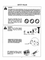
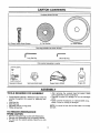
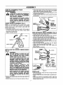
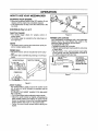
iMPORTANT MANUAL
Do Not Throw Away
S _AUk S
Operator's
Manual
Model No.
358.798441
Always
Wear Eye Protection
CRAFTSMAN®
ASSISTANCE
cc/1.3 cu. in. 2-CYCLE ENGINE
17" Semi-Automatic Head
GAS WEEDWACKER ®
_
READTHE OPERATOR'S
WARNING:
MANUAL AND FOLLOW
ALL WARNINGS AND
SAFETYINSTRUCTIONS.
FAILURETO DO SO CAN
RESULT IN SERIOUS
INJURY.
•
•
•
•
Assembly
Operation
Customer Responsibilities
Service and Adjustments
Repair Parts
Sears, Roebuck and Co., Hoffman Estates, IL 60179 U.S.A.
530-083680-1-03/16/95
SAFETY RULES
J
TACT SPARK PLUG TO PREVENT ACCIDENTAL STARTING WHEN SETTING UP, TRANSPORTING,
AUTION; ALWAYS
DISCONNECT
ADJUSTING
OR MAKING
REPAIRS.SPARK PLUG WIRE AND PLACE WIRE WHERE IT CANNOT CON-/
I&
OPERATOR
•
•
•
•
•
•
•
SAFETY
"
Always wear safety eye protection
Always wear long pants, long sleeves, boots and
gloves_ Wearing safety leg guards is recommended.
Do not go barefoot or wear sandals, short pants, short
sleeves_ Being fully covered helps to protect you from
pieces of toxic plants thrown by the cutting head_
Secure hair so it is above shoulder length. Secure
loose clothing, jewelry, or clothing with loosely hanging ties, straps, tassels, etc.; they can be caught in
moving parts_
Do not operate this unit when you are tired, ill, or
under the influence of alcohol, drugs, or medication
Wear hearing protection if you use this unit for more
than 1-1/2 hours per day.
Never start or run the engine inside a closed room or
building Breathing exhaust fumes can kill
Keep handles free of oil and fuel
If situations occur which are not covered in this
manual, use care and good judgement
UNIT/MAINTENANCE
SAFETY
Look for and replace damaged or loose parts before
each use. Look for and repair fuel leaks before use
Keep the unit in good working condition.
• Use only 080" diameter monofilament line Never use
wire, rope, string, etc.
Keep the cutting line at the proper length
Make sure the unit is maintained and assembled correctly as listed in this manual
Install the required shield properly before using the
unit
Use only the specified trimmer head.
• Make carburetor adjustments with the lower end supported to prevent the trimmer line from contacting any
object Hold unit by hand.
• Keep others away when making carburetor adjustments
• Use only good quality SEARS accessories as recommended for this unit
FUEL
•
•
•
Do notsmoke or allowsmoking near fuel or the unitor
while using the unit
. Wipe up all fuel spills before starting engine_
Move at least 10 feet (3 meters) away from fueling site
before starting engine,
o Stop engine and allow unit to cool before removing
fuel cap
CUTTING
Inspectthe area to be cut before each use. Remove
objects (rocks, broken glass, nails, wire, string, etc)
which can be thrown or become entangled in tire
semi-automatic line head
= Keep others including children, animals, bystanders
and helpers at least 50 feet (15 meters) away Stop
the engine immediately ifyou are approached.
o Always keep the engine on the right-hand side of your
body
o Hold the unit firmly with both hands_
• Keep firm footing and balance Do not over-reach
• Keep the semi=automatic line head below waist level,
o Do not raise the engine above your waist
• Keep all parts of your body away from semi-automatic
line head and mufflerwhen engine is running,
• Cut from your rightto your left
° Use onlyfor jobsexplained in this manual
TRANSPORTING
•
•
•
SAFETY
Mix and pour fuel outdoors
Keep away from sparks or flames
Use a container approved for fuel
SAFETY
•
AND STORAGE
Stop the unit before transporting
Allow the engine to coo!, and secure ttle unit before
storing or transporting in a vehicle
Empty the fuel tank before storing or transporting the
unit Use up any fuel left in the carburetor by starting
the engine and letting the engine run until it stops
Store unit and fuel in an area where fuel vapors cannot reach sparks or open flames from water heaters,
electric motors or switches, furnaces, etc_
Store unitso the line limiter cannot accidentally cause
injury
Store the unit out of the reach of children
SAFETY NOTICE
Exposureto vibrations
throughprolongeduse of gasolinepoweredhandunitscouldcausebloodvesselor nerve damagein the
fingers,hands,and joints of peopleproneto circulation
disordersor abnormalswellings.Prolonged
use incold weatherhas been
linkedto blood vesseldamage in otherwisehealthy people, tfsymptomsoccur such as numbness,pain, loss of strength,change
in skin color or texture, or loss of feeling in the fingers, handsor joints,discontinue
the use of this unit and seek medical attention. An anti-vibrationsystem does not guaranteethe avoidanceof these problemsUserswho operatepower tools on a continual and regular basis must monitor closelytheir physical conditionand the conditionof this unit.
LOOK
FOR --THIS
SYMBOL TO
POINT OUT
IMPORTANT
SAFETY ISPRECAUTIONS.
IT
MEANS
A'n'ENTION!!!
BECOME
ALERT!!!
YOUR SAFETY
INVOLVED.
-2-
SAFETY RULES
DANGER
THIS POWER UNIT CAN BE DANGEROUS! THIS UNIT CAN CAUSE SERIOUS INJURY OR
BLINDNESS TO THE OPERATOR AND OTHERS. THE WARNINGS AND SAFETY INSTRUCTIONS IN
THIS MANUAL MUST BE FOLLOWED TO PROVIDE REASONABLE SAFETY AND EFFICIENCY IN
USING THIS UNIT. THE OPERATOR IS RESPONSIBLE FOR FOLLOWING THE WARNINGS AND
INSTRUCTIONS IN THIS MANUAL AND ON THE UNIT. READ THE ENTIRE OPERATOR'S MANUAL
BEFORE ASSEMBLING AND USING THE UNIT! RESTRICT THE USE OF THIS POWER UNIT TO
PERSONS WHO READ, UNDERSTAND AND FOLLOW THE WARNINGS AND INSTRUCTIONS IN
THIS MANUAL AND ON THE UNriP.NEVER ALLOW CHILDREN TO USE THIS TOOL.
THIS UNIT IS DESIGNED
FOR LINE
TRIMMER USE ONLY, NEVER USE ANY
OTHER CUTTING ATTACHMENT WITH
THIS
UNIT.
BLADES
AND HEADS
WITH FLAILING DEVICES CAN CAUSE
SERIOUS INJURY.
000
WARNING
TRIMMER LINE CAN THROW OBJECTS
VIOLENTLY. YOU CAN BE BLINDED
OR INJURED. WEAR EYE AND LEG
PROTECTION.
IIII
PROTECTION
BOOTS
HAZARD ZONE FOR THROWN OBJECTS.
TRIMMER LINE CAN THROW OBJECTS
VIOLENTLY. OTHERS CAN BE BLINDED
OR INJURED_ KEEP PEOPLE AND ANIMALS 50 FEET (15 METERS)AWAY.
HAZARD ZO E_
READ OPERATOR'S MANUAL. FOLLOW
ALL WARNINGS AND INSTRUCTIONS.
FAILURE TO DO SO CAN RESULT IN
SERIOUS INJURY.
LEG GUARDS
CONGRATULATIONS on your purchase of a Sears
Craftsman Gas Weedwacker. It has been designed,engineered and manufactured to give you the best possible
dependabilityand performance.
PRODUCT SPECIFICATIONS
CUTTING
PATH
..................
17"
TRIMMER LINE ....................
080" Diameter
SEMI-AUTOMATIC
HEAD ROTATION ...............
Counterclockwise
(for operator)
ENGINE ................................
21cc, 2..cycle Air Cooled
Should you experience any problems you cannot easily
remedy, please contact your nearest Sears Service CenterJDepartment, Sears has competent, well trained technicians and the proper tools to service or repair this unit..
FUEL!OIL MIX RATIO...... 40:t (3.2 ez. oil per gallon
Please read and retain this manual. The instructionswill
enable you to assemble and maintain your unit properly.
Always observe the "SAFETY RULES/'
gas)
IGNITION .....................................
Solid State
(air gap .010" to .014")
IGNITION TIMING .................
Non-adjustable, Fixed
MODEL
NUMBER:
358°798441
DATE CODE/SERIAL
SPARK PLUG ..........................
Champion (RCJ-aY)
NO.:
SPARK PLUG GAP ................
025" (6rnm)
DATE OF PURCHASE:
ENGINE RPM..........................
8,000 RPM Max
THE MODEL AND SERIAL NUMBER WILL BE FOUND
ON THE PRODUCT
SPECIAL NOTICE
Foruserson U.S ForestLandandin some states, including
California (Public Resources
Codes4442 and 4443), Idaho,
Maine. Minnesota_
New Jersey,Oregon,and Washington:
Certain internalcombustionenginesoperated on forest.
brush, and/orgrass-covered
landsin the above areas are
requiredto be equippedwitha spark arrestor,maintained in
effectiveworkingorder,or the engine must be constructed,
equipped,and maintainedfor thepreventionof fire. Check
withyourstateor localauthorities
for regulationspertaining
to theserequirementsFailureto follow theserequirements
isa violationofthelaw Thisunitisnot factory-equipped with
a spark arrestor;however,a sparkarrestor isavailableas an
optionalpart If a sparkarrestorisrequired in yourarea, contactyourSEARSServiceCenter/Department
for the correct
kit.
YOU SHOULD RECORD
BOTH SERIAL NUMBER
AND DATE OF PURCHASE
AND KEEP IN A SAFE
PLACE FOR FUTURE REFERENCE
MAINTENANCE
AGREEMENT
A Sears Maintenance Agreement'is available on this product Contact your nearest Sears Store for details
CUSTOMER
RESPONSIBILITIES
Read and observe the safety rules_
Follow a regular schedule in maintaining, caring for, and
using your unit
Follow the instructions under "Customer Responsibilities" and "Storage" sections of this Operator's Manual.
Ma_ulacluted _n_tet one ot mote of Ihe fotlow_ng US patenls: 5 383_427; 5,367.986
5 345 684.5 343 631; 6 376 968; 6269 663; 6 020,223:4 940 026; 4 897 923; 4 852 258:
4 846,123 4 84t 926. 4 635867; 4825 548: 4633465; 4 819 742, 4 796 f85:4 506 066;
4 483,069. 4 451 963:4 366,623:4366 62t; 4 352243; 4 347 _66; 4 290 200; 4 266.675:
4 236.3t 2; 4,177561; 4,172.322: 4.167,812; 4.162.675; 4.161,820; 4 122 653; 4,104,797:
Re 33.266:C3_4 088; O334C51; 0304 196; C276 160 Olhet U S and foreign patents
pendln6
FULL ONE YEAR WARRANTY ON CRAFTSMAN GAS-POWERED
WEEDWACKER ®LINE TRIMMER
For one year from the date of purchase, when this Craftsman Gas-Powered Weedwacker_ LineTrimmer is maintairled
lubricated and tuned-up according to the operating and maintenance instructions in the operator's manual, Sears will
repair, free of charge, any defect in materials or workmanship.
This warranty excludes nylon line, spark plug, and air filter, whichare expendable parts and become worn during normal use.
If this Weedwacker_ Line Trimmer is used for commemia! purposes, thiswarrantyapplies for only 90 days from the date
of purchase. If this Weedwacker_ Line Trimmer is used for rentalpurposes,this warrantyapplies for only 30 days from
date of purchase.This warranty applies only while this productis in use in the United States.
WARRANTY SERVICE IS AVAILABLE BY RETURNING THE WEEDWACKER®LINE TRIMMER TO THE NEARES"
SEARS SERVICE CENTER IN THE UNITED STATES.
This warranty gives you specific legal dghts, and you may also have other rightswhich vary from state to state.
SEARS, ROEBUCK AND CO., DI817WA, HOFFMAN ESTATES, IL 60179
-4-
CARTON CONTENTS
i
i
Hardware shown full size
14)Plastic Debris Shield Screws
(1) Flat Washer
(1) Grass Washer
Parts bag contents not shown full size
Long Hex Key
Short Hex Key
Parts packed separately in carton
1_,3¸-
©
:=
Operator's Manual
Semi-automatic Head
Plastic Debris Shield
Engine Oil
ASSEMBLY
TOOLS
REQUIRED
FOR ASSEMBLY
• After removing the contents from the carton, check
parts against the Carton Contents list
• Examine the parts for damage. Do not use damaged
parts.
• Notify Customer Assistance at 1-800-235-5878 immediately if a part is missing or damaged,
• Torque Wrench (optional)- Reference torque values are
provided throughout this manual for tightening hardware,,
• Long Hex Key
• Short Hex Key
• Adjustable wrench or large pliers
• Phillips Screwdriver
NOTE: It is normal to hear the fuel filter rattle in an empty
fuel tank,
TO REMOVE WEEDWACKER
FROM CARTON
• Remove loose parts bag included with Wesdwacker,
• Remove your Weedwackerfrom the packing material
• You may use the opened packing material as a work
surface
-5-
TABLE OF CONTENTS
Safety Rules ..............................................................................................
2
Customer' Responsibilities ....................................................
14
Product Specifications .........................................................................
4
Service and Adjustments ..............................................................
17
Warranty ................................................................................................
4
Storage ......................................................................................
20
Accessories ...............................................................................................
6
Trouble Shooting ............................................................................
21
Assembly ...............................................................................................
7
Repair Parts .................................................................................
22
Operation .....................................................................................................
8
Repair Parts Ordering/Service .................................
Back Cover
iNDEX
A
K
Know Your Weedwacker ............................................................
8
Accessories ..............................................................................................
6
L
Adjustments
Line Advancement .................................................................
9
Assist Handle ................................................................. 7
Carburetor ..............................................................................
17
Line Replacement..........................................................................
17
M
Air Filter ....................................................................................................
15
Maintenance Schedule ...........................................
:................
14
Assembly .......................................................................................................
6
Model Number ...............................................................................
4
Assist Handle ...................................................................................................
7
O
C
Operation ......................................................................................
8
Carburetor Adjustments .......................................................................
19
Carton Contents .........................................................................................
5
Ordering Repair Parts ..................................................
Back Cover
Controls ..........................................................................................
9
R
Customer Responsibilities ..................
:..........................................
14
Repair Parts ....................................................................................
22
Ordering ................................................................................
Back Cover
Spark Plug .....................................................................................................
4
S
Cutting Techniques ...............................................................
11
D
Service and Adjustments .......................................................
17
Debris Shield ...........................................................................................
7
Spark Arrestor Screen ...................................................................
15
Drive Shaft Lubrication...............................................................
14
Specifications ..................................................................................
4
E
Starting .......................................................................................
13
Engine
Storage ...........................................................................................
20
T
Fuel/Oil .........................................................................................
12
Spark Plug ......................................................................................
4
Trouble Shooting ............................................................................
21
W
Starting ..............................................................................................
13
Storage ............................................................................................
20
Warranty .........................................................................................
4
F
Fueling ......................................................................................................
12
Fuel Filter ..................................................................................................
16
ACCESSORIES
These accessories and attachments were available when the unit was originally purchased, They are also available at
most Sears retail outlets and service center& Most Sears stores can order these items for you when you provide the model
number of your unit
Accessories
I
SAFETY
GOGGLES
HEARING
PROTECTION
SEMIAUTOMATIC
LINE HEAD
SPOOL
WITH UNE
BULK
LINE
SPARK
PLUG
I
AIR
FILTER
GAS
CAN
SEARS
2*CYCLE
ENGINE OIL
P_
©
.080"
80 FT.
200 FT.
400 FTo
*6-
3.2 oz.I
40:1
I
ASSEMBLY
HOW TO ASSEMBLE
WEEDWACKER
i_
• Place plastic debris shield under the gear box and align
screw holes. Make sure the widest part of the plastic
debris shield is pointing toward the engine.
• insert the four shield screws through the gear box into
the plastic debris shield,
• Tighten screws evenly and securely using the long hex
key provided
YOUR
IF THIS UNIT IS RECEIVED ASSEMBLED,
WARNING:
REVIEW ALL STEPS IN THIS ASSEMBLY
SECTION FOR PROPER ADJUSTMENT
AND CORRECT ASSEMBLY.
WHEN ADJUSTING THE ASSIST HANDLE
FOR COMFORT, BE SURE THAT THE
ASSIST HANDLE REMAINS BETWEEN
THE TRIGGER HOUSING AND THE SAFETY LABEL.
GEAR BOX
HOUSING
PLASTIC
DEBRIS SHIELD
ASSIST HANDLE ASSEMBLY (Fig. 1)
NOTE: For pre-assembled units, simply loosen assist
handle knob and rotate assist handle to the operating
position, being sure to align between safety label and
throttte trigger housing
• Rotate assist handle from left to right to tilt the angle of
the semi-automatic head when cutting a large, sloped
area such as a ditch bank
Tighten T-handle securely
THE
Figure 1
PLASTIC
DEBRIS
I ARBOR SHAFT
Figure 2
SEMI-AUTOMATIC
HEAD ASSEMBLY
(Fig. 3)
Ensure the plastic debris shield is in place and securao.
• install dust cup over the arbor shall
Align the hole in the dust cup with the hole in the center front of the gear box by turning the dust cup.
• Install the grass washer over the arbor shaft. Make sure
the grass washer is against and curved over the dust cup.
• Install the flat washer over the arbor shaft.
• Start threading the semi-automatic head onto the arbor
shaft (counterclockwise)
• Insert the short hex key (provided) into the aligned
holes to keep the arbor shaft from turning
• Tighten the semi-automatic head while holding the
short hex key.
Remove the short hex key
GEARBOX
SHIELD
(Fig. 2)
i_
REMOVEDFOR
INSTALLATION)
r
INSTALLING
DUST CUP
WIDEST PART
OF SHIELD
THE LINE LIMITER IS SHARP AND CAN
WARNING:
CUT YOU. BE SURE TO WEAR GLOVES
WHILE WORKING WITH THE PLASTIC
DEBRIS SHIELD OR LINE LIMITER.
THE PLASTIC DEBRIS SHIELD MUST BE
PROPERLY INSTALLED FOR ALL LINE
TRIMMER USAGE. THE DEBRIS SHIELD
PROVIDES PARTIAL PROTECTION FROM
THE RISK OFTHROWN OBJECTSTOTHE
OPERATOR AND OTHERS.
WHEN INSTALLED CORRECTLY, THE
PLASTIC DEBRIS SHIELD WILL BE IN
PROPER ALIGNMENT. FAILURE TO INSTALL THE DEBRIS SHIELD IN POSITION
SHOWN IN ILLUSTRATION CAN RESULT IN
SERIOUS INJURYTO THE OPERATOR.
WHEN ADJUSTING THE ASSIST HANDLE
FOR COMFORT, BE SURE THAT THE
ASSIST HANDLE REMAINS BETWEEN
THE TRIGGER HOUSING AND 'THE SAFETY LABEL.
UNE
LIMITER"
TRIMMER
HEAD
DIRECTION
TO INSTALL
Figure 3
CHECK LIST
• Check all fasteners, make sure they are tightand there
are no loose parts.
• Check to make sure the throttle cable is positioned correctly,
• With the unit hetd in the operating position, adjust the
assist handle up or down the tube for best comfort and
balance before first use
Remove the packing cover from the arbor shaft if so
equipped
• Remove fhe dust cup from the arbor shaft (ref Fig, 2)°
*7-
OPERATION
KNOW YOUR WEEDWACKER
(Fig. 4)
READ THIS OPERATOR'S MANUAL AND SAFETY RULES BEFORE OPERATING YOUR WEEDWACKER Compare
the illustrations with your unit to familiarize yourseff with the location of the various controls and adjustments. Save this
manual for future reference,
MUFFLER
AND GUARD
ASSIST
HANDLE
SERIAL NO/
DATE CODE DECAL
THROTTLE /
GRIP
SAFETY
LABEL
SPARK PLUG
PRIMER BULB
MOMENTARY
SWITCH
CHOKE LEVER
STARTER
ROPE
HANDLE
R FILTER COVER
STARTING
INSTRUCTIONS
DEBRIS SHIELD
/
LINE
LIMrfER
THROTTLE
TRIGGER
FUEL
CAP
SEMI-AUTOMATIC
HEAD
Figure 4
The MOMENTARY SWITCH is used to stop the engine.
The CHOKE LEVER activates the choke to provide additional fuel to the engine when starting a cold engine.
The STARTER ROPE HANDLE is used for starting the
engine,
The PRIMER BULB circulates fuel to the carburetor.
The THROTTLE TRIGGER controls engine speed.
The SEMI-AUTOMATIC HEAD contains spool of line
which advances when head is tapped on the ground,
The ASSIST HANDLE aids in the control of the unit.
The LINE LIMITER cuts trimmer line automatically to the
correct length
-8 =
OPERATION
HOW TO USE YOUR WEEDWACKER
'l \
_'_
_
STOPPING YOUR ENGINE
• Move the momentary switch to the OFF position_Do not
release until the engine has completely stopped,
• If the engine does not stop. move the choke lever to the
full choke.
ASSIST
LABEL
CONTROLS (Fig. 5, 6 & 7)
T-HANDLE
THROTTLE TRIGGER
• The throttle trigger allows for variable control of
engine speed.
• The throttle trigger is actuated by the index finger on
your right hand,
Figure 6
TRIMMER LINE ADVANCE
Your Weedwacker is equipped with a semi-automatic
trimmer head, The most efficient line length is the
maximum length allowed by the line limiter_
TO ADVANCE THE LINE:
• Operate the engine at full throttle,
• Hold the semi-automatic head parallel to and above
a grassy area
• Tap the bottom of the semi-automatic head lightly
on the ground one time. Approximately 2 inches of
line will be advanced with each tap.
CHOKE
• The choke is set by moving the choke lever up fully for
cold or refueled engine starts
PRIMER BULB
• The primer bulb is used to circulate fuel to the carburetor.
• The pdmer bulb is activated by pressing on it with your
thumb.
CHOKE POSITIONS
TO ADVANCE
LINE, TAP BOTi'OM
OF SEMI.AUTOMATIC HEAD ON
THRO3-rLE TRIGGER
I
GROUND ONE TIME
UNE LIMITER
Figure 7
Figure 5
ASSIST HANDLE
The assist handle is used to aid in the control of the
unit, as well as a barrier between the operator and the
cutting head.
TO ADJUST THE ASSIST HANDLE FOR BALANCE
AND CONTROL:
• Turn off the engine before adjusting assist handle.
• Adjust the assist handle by slightty unthreading the
assist handle screws and rotating the assist handle
forward or backward. Ensure the mounting brackets
remain between the arrows on the assist handte
• Tighten the assist handle screws before starting the
engine,
-9
-
OPERATION SAFETY
LINE TRIMMER
SAFETY
THE RAPIDLY MOVING LINE CAUSES OBJECTSTO BE
WARNING:
THROWN
VIOLENTLY. THE DEBRIS SHIELD WILL NOT
PROVIDE COMPLETE PROTECTION TO THE OPERATOR
OR OTHERS. THE OPERATOR MUST WEAR A SAFETY
FACE SHIELD OR GOGGLES. ALWAYS WEAR HEAVY,
LONG PANTSAND BOOTS. KEEP OTHERS AT LEAST50
FEET (15 METERS)AWAY.
THIS UNIT'WILL THROW OBJECTS AND CUT. KEEP OTHERS
INCLUDING CHILDREN, ANIMALS, BYSTANDERS AND
HELPERSAT LEAST50 FEET(15 METERS) AWAY FROM THE
OPERATOR AND UNIT. STOP THE ENGINE IF YOU ARE
APPROACHED.IN AREAS WHERE OTHER PEOPLEAND ANIMALS ARE PRESENT, SUCH AS NEAR SIDEWALKS,STREETS,
HOUSES, ETC. IT IS STRONGLY RECOMMENDEDTHAT THE
OPERATORUSE THE BUDDY SYSTEM;THAT IS, HAVEANOTHER PERSON SERVE AS A "LOOK-OUT," KEEPING HIMSELF
AND OTHERS AT LEAST50 FEET (15 METERS) AWAY FROM
THE OPERATOR_
SEMI-AUTOMATIC LINE HEAD PARTS THAT ARE CHIPPED,
CRACKED OR DAMAGEDIN ANY OTHERWAY CANFLY APARTAND
CAUSESERIOUSINJURY.DO NOT USE. REPLACEDAMAGEDPARTS
BEFORE USINGTHE UNIT.
OPERATOR
SAFETY
• Always wear eye protection when operating, Servicing,
or performing maintenance on your unit. Refer to
"Accessories?
o Do not operate this unit when you are tired, ill, or under
the influence of alcohol, drugs or medication..
• Always wear heavy, long pants, long sleeves, boots,
and gloves Do not go barefoot or wear sandals, short
pants Loose clothing, jewelry or clothing with loosely
hanging straps, ties, tassels, etc. can be caught in
moving parts. Secure flair so it is above shoulder
length_Being tully covered will help protect you from
pieces of toxic plants such as poison ivy thrown by the
semi-automatic head, which could be more of a hazard
than touching the plant itself.
• Do not swing the unit with such force that you are in
danger of losing your'balance
• Never start or run the engine inside a closed room or
building. Breathing exhaust fumes car] kill
• Keep handles free of oil and fuel
UNIT
•
•
•
•
•
•
•
SAFETY
Inspectthe entire unit before each use Replace damaged parts. Check for fuel leaks and make sure all fasteners are in place and securely fastened..
Use only .080" diameter good quality monofilament
lineoNever use wire, rope, or string, etc.
Be sure the debris shield is properly attached
Make sure semi-automatic line head is properly
installed and securelyfastened Refer to "Assembly_"
Make carburetor adjustments with the drive shaft
housing supported to prevent the semi-automatic line
head from contacting any object
Keep othersaway when making carburetoradjustments
Use only good quality SEARS accessories or attachments_
-10-
FACE
SHIELD
SEMI-AUTOMATIC HEAD
©
USE ONLY GOOD QUALITY
REPLACEMENT PARTS
CU'I-rlNG SAFETY
Inspect the area to be cut before each use Remove
objects (rocks, broken glass, nails, wire, string, etc.)
which can be thrown or become entangled in the semiautomatic line head
° Always keep the engine on the right side of your body.
• Hold the unit firmly with both hands
Keep firm footing and balance Do not over-react]
• Keep the semi-automatic line head below waist level
• Do not raise the engine above your waist.
- Keep all parts of your body away from the semi-automatic line head and muffler when engine is running
° Use only for jobs explained in this manual
• Cut at full throttle.
• Cut from your right to your left
OPERATION
OPERATING
TECHNIQUES
TIPS (Fig. 8)
(Fig. 9, 10, 11 & 12)
• TRIMMING - Allow only the tip of the line to make
contact Do not force trimmer line into work area,
WARNING:
USE MINIMUM SPEED AND DO NOT
CROWD THE LINE WHEN CUTTING
AROUND
HARD
OBJECTS (ROCK,
GRAVEL, FENCE POSTS, ETC.) WHICH
CAN DAMAGE THE SEMI-AUTOMATIC
HEAD, BECOME ENTANGLED IN THE
LINE, OR BE THROWN CAUSING A SERIOUS HAZARD.
REMEMBER
Keep semiautomatic line head
3 inches above
the ground while
trimming
Figure 9
ALWAYS WEAR EYE PROTECTION. NEVER LEAN OVER THE SEMI-AUTOMATIC
LINE HEAD. ROCKS OR DEBRIS CAN
RICOCHET OR BE THROWN INTO EYES
AND FACE AND CAUSE BLINDNESS OR
OTHER SERIOUS INJURY°
• SCALPING - The scalping technique removes
unwanted vegetation Allow the tip of the line to strike
the ground around trees, posts, monuments etc This
technique increases line wea_
SCALPING
1:
For trimming or scalping, use partial throttle to
increase line life especially:
- dudng light duty cutting
- near objects around which the line can wrap or wear
line such as small posts trees fence wire or concrete
- The line will easily remove grass and weeds from
around walls, fences trees and flower beds; but it also
can cut the tender bark of trees or shrubs and scar
fences To help avoid damage especially to delicate
vegetation or trees with tender bark, shorten line to 45 inches and use at partial throttle
• The tip of the line does the cutting You will achieve the
best performance and minimum line wear by not
crowding the line into cutting area
• Always release throttle trigger and allow engine to
retum to idle speed when not cutting
- Hold bottom of the semi-automatic head about 3
inches above ground and at an angle
__
//
•
Figure 10
• MOWING - Your tdmmer is ideal for mowing in places
conventional lawn mowers cannot reach Keep the
line parallel to the ground
_J
18
MOWING
Figure 11
• SWEEPING - The fanning action of the rotating line
_
__/_.._.
INTOWORKAREA
line parallel to and above the surfaces being swept
_.
and move unit from side to side
; 3 INCHES
r _1_
LINECROWDEDII
l
can be used for a quick and easy clean up Keep the
WRONG
Figure 8
SWEEPING
Figure 12
11
OPERATION
BEFORE
&
STARTING
ENGINE:
2-CYCLE AIR-COOLED
ENGINE OIL
WARNING:
BE SURE TO READ THE FUEL SAFETY
INFORMATION IN THE SAFETY RULES
SECTION ON PAGE 2 OF THIS MANUAL
BEFORE YOU BEGIN°
CRAFTSMAN 40:1 2-cycle engine oil (AIR-COOLED) is
strongly recommended This oil is specially blended with
fuel stabilizers for increased fuel stability (extends fuel life
up to 5 times longer) and reduced smoke
IF YOU DO NOT UNDERSTAND THE FUEL
SAFETY SECTION DO NOT ATTEMPT TO
FUEL YOUR UNIT; SEEK HELP FROM
SOMEONE THAT DOES UNDERSTAND
THE FUEL SAFETY SECTION OR CALL
THE CUSTOMER ASSISTANCE HOTLINE
AT 1-800-235-5878.
If CRAFTSMAN 2-cycle engine oil (AIR-COOLED) is not
available, use a good quality 2-cycle engine oil (AIRCOOLED) that has a recommended fuel mix of 40:1
IMPORTANT! Do not use:
o AUTOMOTIVE OIL
° BOAT OILS (NMMA, BIA, etc,)
GASOLINE
The two-cycle engine on this product requires a fuel
mixture of regular unleaded gasoline and a high quality
40:1 2-cycle engine oil (AIR-COOLED) for lubrication of
the bearings and other moving parts. The correct fuel/oil
mixture is 40:1 (see Fuel Mixture Chart), Too little oil or
the incorrect oil type will cause poor performance and
may cause the engine to overheatand seize.
Gasoline and oil must be premixed in a clean approved
fuel container. Always use fresh regular unleaded gasoline.
This engine is certified to operate on unleaded gasoline.
IMPORTANT: Experience indicatesthat alcohol blended
fuels called gasohol (or using ethanol or methanol) can
attractmoisture,whichleads to oil/gasseparation and formation of acids during storage Acidic gas can damage
the fuel system of an engine while in storage_ To avoid
engine problems, the fuel system should be emptied
before storage for 30 days or longer. Drain the gas tank,
then run the fuel out of the carburetorand fuel lines by
startingthe engine and letting itrun untilit stops Use fresh
fuel next season See STORAGE instructionsfor additional information Never use engine or carburetorcleaner'
products in the fuel tank or permanent damage may
occur
FUEL STABILIZER
Fuel stabilizer is an acceptable alternative in minimizing
the formation of fuel gum deposits during storage Add
stabilizer to gasoline in fuel tank or storage container.
Always follow the fuel mix ratio found on the stabilizer
container Run engine at least 5 minutes after adding stabilizer to allow the stabilizer to reach the carburetor You
do not have to drain the fuel tank for storage if you are
using fuel stabilizer
CRAFTSMAN 40:1 2-cycle engine oil (AIR-COOLED) is
specially blended with fuel stabilizers If you do not use
this Sears oil, you can add a fuel stabilizer (such as
CRAFTSMAN No. 33500) to your fuel tank.
-12-
These oils do not have proper additives for 2-cycle AIRCOOLED engines and can cause engine damage.
GASOLINE AND OIL MIXTURE
Mix gasoline and oil as follows:
• Consult chart for correct quantities..
• Do not mix gasoline and oil directly in the unit's fuel
tank,
FOR ONE GALLON:
- Pour 3.2 ounces of high quality, 2*cycle engine oil
(AIR-COOLED) into any empty, approved one gallon
gasoline container
° Add one gallon of regular unleaded gasoline to the
gallon container,then securely replace the cap.
• Shake the container.
° The mixture is now read,/for use. Fuel stabilizer can
be added at this time if desired; follow mixing instructionson the label.
FUEL
MIXTURE
CHART
40:1 Fuel:Oil Mix Ratio
Gasoline
1 gallon
2 5 gallons
3.2
80
NOTE: Fuel containers may hold more than the specified
amounL If too much gasoline is in the container, the
resulting gas-to*oil fuel mixture will not be correct for
proper engine operation
OPERATION
STOPPING
YOUR ENGINE
• Move the momentary switch to the OFF position. Do not
release until the engine has completely stopped.
• If the engine does not stop, move the choke lever to the
full choke.
_
THE SEMI-AUTOMATIC LINE HEAD WILL
ARNING:
TURN
WHEN THE ENGINE STARTS°
NOTE: If the engine dies with choke lever at "Off Choke"
position,movethe choke lever to "Half Choke" Pull starter
rope three times, Move choke lever to "Oft Choke" position, pull the rope until engine runs. Run engine 30 seconds with throttle trigger fully squeezed,
. To stop the engine, push and hold the momentary
switch in the "Off" position; do not release until the
engine has completely stopped.
STARTING
A WARM ENGINE
• Move choke lever to the "Off Choke" position.
. Squeeze throttle trigger.
o Pull starter rope until engine starts
FOR SAFE STARTING AND OPERATION,
FOLLOW ALL SAFETY PRECAUTIONS
IN THIS OPERATOR'S MANUAL AND
LABELS ON THE UNIT, DRESS PROPERLY BEFORE STARTING ENGINE°
AVOID ANY CONTACT W_H THE MUFFLER. A HOT MUFFLER CAN CAUSE
SERIOUS BURNS_
TO START ENGINE
(Fig. 13 & 14)
Figure 14
COLD ENGINE START AND WARM ENGINE
START AFTER RUNNING OUT OF FUEL
• Fuel engine with 40:1 fuel mix (32 oz. to 1 gal gas).
Move 10 feet (3 meters) away from fueling site
STARTING POSITION
DIFFICULT STARTING AND FLOODED ENGINE
The engine may be flooded with too much fuel if it has nat
started after 20 pulls
Flooded engines can be cleared of excess fuel with the
following procedure:
• Move the choke lever to the "Off Choke" position.
° Squeeze and hold the throttle trigger.
• Pull starter rope handle until engine starts.
Starting could require pulling starter rope handle many
times depending on how badly unit is flooded°
If engine still fails to start, refer to "TROUBLE SHOOTING" chart or catl the 1-800 number listed on the front
cover of this manual
Figure 13
- Prime engine by pressing primer bulb six times.
• Actuate choke by moving the choke lever to the "Full
Choke" position.
• Rest engine and debris shield on ground, supporting
semi-automatic line head off ground.
• Squeeze and hold the throttle trigger Keep the throttle
trigger fully squeezed until the engine runs smoothly.
NOTE: When pulling the starter rope, do not use the full
extent of the rope as this can cause the rope to break Do
not let the starter snap back Hold the handle and let the
rope rewind slowly.
• Pull starter rope sharply five times.
The engine may sound as if it is tryingto start before the
fifth pull If so, go to the next step immediately
• Move the choke lever to the "Half Choke" position
• Pull the starter rope sharply until the engine runs, but
no more than six pulls.
Once the engine starts, allow the engine to run 15 seconds, then move the choke lever to "Off Choke" Allow the
engine to run for 30 more seconds at "Off Choke" before
releasing the throttle trigger,
-13-
CUSTOMER
MAINTENANCE
RESPONSiBiLiTIES
SCHEDULE
Fill in dates as you complete
regular service
Before
Use
After
Use
Every
5 Hrs.
Every
25 Hrs
Yearly
Service Dates
Check for darnaqed or wern parts
Check for loosefasteners & parts
Clean unit & labels
,/
Clean air filter
Clean/Inspect
Spark Arrestor Screen (if installed)and
Drive Shaft Lubrication
,/.
v"
Muffler
,/
Replace spark pluq
_Replacefuel filter
Check Gearbox Lubrication
GENERAL
,/
RECOMMENDATIONS
BEFORE
The warranty on this unitdoes not cover items that have
been subjected to operator abuse or negtigence_ To
receive full value from the warranty, the operator must
maintain unit as instructedin this manual
• Blades - replace blades that are bent, warped, cracked
or damaged in any way.
o Semi-automatic head - replace semi-automatic head
parts that are bent, warped, cracked, or damaged in
any way
• Fuel cap - replace broken or leaking fuel cap.
• Debris shields - replace debris shields that are bent,
warped, cracked, or damaged in any way.
• Line limiter - missing or damaged.
Some adjustments will need to be made periodically to
properly maintain your unit.
All adjustments in the "Service and Adjustments" section of
this manual should be checked at least once each season.
• Once a year; replace the spark plug, replace air' filter
element and check blades and semi-automatic head for
wear A new spark plug and a clean/new air filter element assures proper air-fuel mixture and helps your
engine run better and last longer:
• Follow the maintenance schedule in this manual
CHECK FOR LOOSE FASTENERS
PARTS
• Blade nut
• Semi-automatic head
° Assist handle
• Throttle handle
- Cylinder and muffler cover
° Air filter cover
" Muffler
• Line Limiter
WARNING
DISCONNECT THE SPARK PLUG BEFORE
PERFORMING MAINTENANCE EXCEPT
FOR CARBURETOR ADJUSTMENTS.
REPLACE SEMI-AUTOMATIC HEAD PARTS
THAT ARE CRACKED, CHIPPED, OR DAMAGED IN ANY OTHER WAY BEFORE USING
THE UNIT.
AND
AFTER USE
CLEAN UNIT AND LABELS
INSPECT THE ENTIRE UNIT. REPLACE
DAMAGED PARTS. CHECK FOR FUEL
LEAKS AND MAKE SURE ALL FASTENERS
ARE IN PLACE AND SECURELY FASTENED.
LUBRICATION
EACH USE
CHECK FOR DAMAGED OR WORN PARTS
• Clean the unit using a damp cloth with a mild detergent°
• Wipe off the unit with a clean dry cloth
CHART
®General purpose lithium base grease
®General purpose lithium base grease
-14-
CUSTOMER
EVERY
RESPONSIBILITIES
5 HOURS
DRIVE SHAFT LUBRICATION
CLEAN AIR FILTER (Fig. 15)
A dirty air filter decreases the life and performance of the
engine and increases fuel consumption and harmful emissions.
Always clean after 5 tanks of fuel or 5 hours of operation.
Clean more frequently in dusty conditions
• Loosen the screws on the air filter cover enough to
remove the cover from the engine
• Remove air filter from cover
• Squeeze air filter dry and replace in cover
• Re-install the air filter cover, making sure the choke exit
slot is placed over the choke lever
(Fig. 17)
• Loosen the gear box clamp screw and the locating screw
from the gear box.
• Remove the gear box from the tube
• Remove the drive shaft from the tube.
• Check drive shaft for broken wires, twists or kinks, and
replace if damage is found.
o Using a clean cloth, wipe surface of drive shaft thoroughly to remove any grease or dirt.
• Apply a uniform coat of lithium base grease to the entire
surface of the drive shaft
• Inject the remaining contents of the grease tube into the
top of the tube_
• Replace drive shaft in the tube
• Re-assemble the gear box to the tube. Tighten screws
securely
AIR
FILTER
LUBRICATE THE DRIVE SHAFT
AIR FILTER
(2) SCREWS
Figure 15
EVERY 25 HOURS
CLEAN AND INSPECT
SCREEN (Fig. 16)
SPARK ARRESTOR
As the unit is used, carbon deposits build up on the muffler
and spark arrestor screen (if installed), and must be
removed to avoid creating a fire hazard or affecting engine
performance
Required cleaning is every 25 hours of operation or annually, whichever is less..
Figure 17
YEARLY
Replace the spark arrestor screen if breaks occur
CLEANING THE SPARK ARRESTOR SCREEN
• Loosen and remove the 2 muffler guard screws.
• Remove the muffler guard.
• Remove the muffler cover retaining springs.
• Remove muffler diffuser and spark arrestor screen
assembly. Notice the orientation of these parts for
reassembly.
• Clean the spark arrestor screen with a wire brush or
replace if breaks are found in the screen
• Replace any broken or cracked parts.
• Reinstall diffuser and spark arrestor screen assembly
o Reinstall muffler cover and the two muffler cover retaining springs
• Reinstall muffler guard and the two muffler guard screws
(15-20 ftolbs.)
REPLACE SPARK PLUG (Fig. 18)
The spark plug should be replaced each year to ensure the
engine starts easier and runs better. Spark plug gap
should be .025".
• Twist, then pull off spark plug boot.
• Remove spark plug from cylinder and discard.
• Replace with correct spark plug and re-tighten with spark
plug wrench (10-12 ft lb.)
• Reconnect spark plug boot
_
sO'ARK PLUG
SPARK PLUG
Figure
Figure 18
16
-15-
l
CUSTOMER RESPONSIBILITIES
REPLACE
FUEL FILTER (Fig. 19 & 20)
• Run fuel tank dry of fuel before proceeding with this
step
• Remove fuel cap and allow it to hang to side of motor:
• Using a small pair of needle nose pliers, grasp fue! cap
retainer, holding it in tank opening and pul! ouL
• With cap out of tank, use a small section of bent wire
similar to that shown in the illustration to catch fuel line
and slowly pull from tank When rue! filter appears in
opening, grasp with fingers and remove from tank.
• Once filter is out of tank, hold fuel line close to fuel filter Remove fuel filter by twisting and pulling at the
same time.
Replace fuel filter.
Reverse process for installation
RETAINER
T WIRE
UEL LINE
FUEL LINE
FUEL
i,L,E.
BARREL
_ _q_"*
FUEL CAP
NECK
Figure 20
GEAR BOX LUBRICATION
(Fig. 21)
" Remove the gear box screw using a wrench.
• Fill gear box with lithium base gear' grease,
• Replace and tighten gear box screw securely°
Figure 19
GEARBOX
GEAR BOX
WASHER
SCREW
Figure 21
-16-
SERVICE AND ADJUSTMENTS
LINE REPLACEMENT
A
NOTE: If tap button gets knocked out of the hub,
reassemble parts as follows:
• Remove the cover and spool,
- Place the spring in the hub cylinder.
• Place the tap button over the spring and hub cylinder.
- Align the slots in the tap button with the fins in the base
of the hub.Push parts together
. Reinstall the spool and cover
WARNING:
TRIMMER
HEAD PARTS THAT ARE
CHIPPED, CRACKED, BROKEN, OR DAM_
AGED IN ANY OTHER WAY CAN FLY
APART AND CAUSE SERIOUS INJURY.
DO NOT USE. REPLACE DAMAGED
PARTS BEFORE USING THE UNITo
INSTALLING
NEW LINE ON SPOOL (Fig. 27)
To replace the line on existing spool:
• Follow "installing Spool with Line Already Wound" steps
and remove any line remaining on the spool
- Use a 25 foot length of SEARS .080" diameter line.
o Insert about 1/4 inch of the end of the line through the
hole in the inner rim of the spool, Allow no more than
1/2 inch of line to extend beyond the rim to avoid interference with tapping action.
• Wrap the line on the spool as shown by the arrow.
NOTE: The line must be wrapped firmly and evenly for
proper line feed.
• Follow "Installing Spool with Line Already Wound"steps
to complete assembly.
° If line breaks off or backs up in the semi-automatic
head, follow "Installing Spool with Line Already Wound"
steps. Pu!l slack in line until the line is tightly wound on
spool, leaving 4-6 inchesof extended line.
THE LINE SAVER MUST BE INSTALLED
ONLY FROM THE INSIDE OFTHE HUB. IF
INSTALLED ON THE OUTSIDE OF THE
HUB,THE
LINE SAVER CAN FLY OFF
AND BECOME A DANGEROUS MISSILE.
USE ONLY .080" DIAMETER
GOOD
QUALITY LINE. NEVER USE WIRE, ROPE,
STRING, ETC.
USE ONLY SPECIFIED SEARS REPLACEMENT PARTS. USE OF OTHER BRANDS
OF REPLACEMENT PARTS CAN CAUSE
DAMAGE TO YOUR UNIT OR INJURY TO
THE OPERATOR OR OTHERS.
DAMAGE/INJURY CAUSED BY USE OF
ACCES SO R IES/ATTACHMENTS
NOT
SPECIFICALLY
RECOMMENDED
BY
SEARS WILL NOT BE REIMBURSED.
IMPORTANT: ALWAYS CLEAN DIRT AND DEBRIS
FROM SPOOL AND HUB WHEN PERFORMING ANY
TYPE MAINTENANCE
LOCK TAB
SPOOL
COVER
INSTALLING
PRE-WOUND
SPOOL
(Fig. 22, 23, 24, 25 & 26)
• Hold the semi-automatic head as shown. Press the two
lock tabs and remove cover. Figure 22
• Remove the lock ring, tap button, and spool
• Clean dirt and debris from all parts. Replace the spool
when the square corners on the lugs are rounded off,
reduced in size, or broken off.Figure 23.
• Find "THIS SIDE UP" on spool and catch the line in the
notch in the bottom ring of the spool, leaving about 4
inches of line hanging from the spool.,
• Insert the end of the line through the line saver
• Press spool into the hub, then turn spool enough to lock
lugs under drive gear lugs. Make sure line is not caught
between the rim of the spool and the wall of the hub.
• Align the line and notch with the line exit hole_ Place
spool in hub. Make sure trimmer line is not caught
between the rim of the spool and the hub,
NOTE: To set the spool in the hub, it may be necessary
to pull the line through the line exit hole until the spool
drops into place.
• Align the lock tabs on the cover over the catches on
the hub, Push the cover down onto the hub until the
parts snap together.
• Check to make sure the lock tabs are properly fastened
as shown_
o Obtain the correct line length (4-6 inches) by pressing
the tap button and pulling on the line agaim
Approximately 2 inches of line can be pulled each time
the tap button is pressed.
\
HUB
LOCK TAB
Figure 22
NORMALLUGS
WORN LUGS
Figure 23
-17-
SERVICE AND ADJUSTMENTS
TAP BUTTON
Figure 24
Figure 26
CATCH
1/4" OF
LINE
Figure 25
Figure 27
-18-
INNER
RIM
SERVICE AND ADJUSTMENTS
Carburetor adjustment is critical and if done improperly can permanently
damage the engine as well as the
carburetor. Please read all instructions and consult the
Troubleshooting
section of this manual before beginning this process. If the engine does not operate
according
to these
instructions
after repeating the
adjusting steps, do not use the unit. For further assistance, please call our customer assistance hotline at
1-800-235-587&
_1_
WARNING:
MAKE CARBURETOR ADJUSTMENTS WITH
THE LOWER END SUPPORTEDTO PREVENT
SEMI-AUTOMATIC HEAD FROM CONTACTING
ANY OBJECT. HOLD UNIT WITH YOUR HAND.
MIXTURE SCREW (WITH MMITER CAP)
IDLE SPEED SCREW
Figure 28
THE SEMI-AUTOMATIC HEAD WILL BE SPINNING DURING MOST OF THIS PROCEDURE.
WEAR YOUR PROTECTIVE EQUIPMENT AND
OBSERVE ALL SAFETY PRECAUTIONS.
IN MIXTURE ADJUSTMENT, RECHECK IDLE
SPEED AFTER EACH ADJUSTMENT. THE
SEMI-AUTOMATIC HEAD MUST NOT MOVE AT
IDLE SPEED°
If engine does not start, it may be flooded If in doubt read
the section on flooded engine in the starting section of this
manual prior to beginning any adjustments.
The carburetor has been adjusted at the factory for sea
level conditions. Ad ustments may become necessary if the
unit is used at significantly higher altitudes or if you notice
any of the following conditions:
- Engine will not idle See "Idle Speed Adjustment" and
"Mixture Speed Adjustment".
o Engine dies or hesitates when it should accelerate See
"Acceleration Check".
• Loss of cutting power which is not corrected by air filter
cleaning See "Mixture Speed Adjustment"
ADJUSTING
PROCEDURE
IDLE SPEED ADJUSTMENT
• Allow the warm engine to idle
• Adjust the Idle Speed until the engine continues to run
without stalling and without the semi-automatic head
turning.
- Turn screw clockwise to increase engine speed if
engine stalls or dies
- Turn screw counterclockwise to slow engine down.
• Follow instructions in "Acceleration Check"
• No further adjustments are necessary if performance is
satisfactory.
MIXTURE ADJUSTMENT
• Support the lower end so the semi-automatic line head is
off the ground and will not make contact with any object
Be sure the trimmer line is extended to the maximum
length allowed by the line limiter.
• Start the engine. Allow engine to idle, then squeeze
throttletrigger fully.
NOTE: Perform steps below at full throttle.
• Turn mixture screw counterclockwiseto the limiter cap
stop
Run engine at full throttle for 30 seconds
If engine Is running rough, turn mixture screw clockwise
in 1/16th turn increments until engine just starts to run
smoothly
• Do not attempt to adjust screw beyond stops as damage
will occur.
• After completing adjustments, check for acceleration.
• If the unit accelerates and runs smoothly, no further
adjustments are necessary. If not, proceed to
"Acceleration Check".
ACCELERATION CHECK
• Allow engine to idle
• Squeeze trigger fully
- If performance is satisfactory (engine accelerates
smoothly), no further adjustments are necessary.
- If the engine does not accelerate smoothly, turn the
mixture screw counterclockwise a small amount (no
more than the width of the slot in the ad usting screw)
• Repeat step above unt I smooth acceleration is obtained
Do not attempt to adjust the screw beyond the stop as
damage will occur.
NOTE: It may be necessary to repeat "Idle speed
Adjustment" through "Acceleration Check;' to obtain correct
adjustments,
NOTE: There are two adjustments on the carburetor
= The Idle Speed Adjustment.
° The Mixture Adjustment..
CARBURETOR
PRESETS
(Fig. 28)
If your engine will not start due to suspected impropercarburetor adjustment, the following presets may be required
If used, it is recommended that all steps withing the adjustment procedure be completed in order to assure a properly set carburetor. If presets are not needed, proceed to section "Idle Speed Adjustment".
When making adjustments, be careful not to force the plastic limiter caps beyond the stops or damage will occur
small adjustments can affect engine performance. It is
important to make slight adjustments and test performance
before proceeding, Each adjustment should be no more
than 1/16th of a turn.
• Turn the mixture adjustment fully counterclockwise to the
limiter cap stops
= Turn idle speed adjustment clockwise one full turn
• If engine fails to start after performing carburetor presets,
the unit may be flooded. Review the "Difficult Starting"
section of the manual If problems continue, call the 1800 number listed on the front cover of this manual for
further assistance.
• Start the engine and operate for three (3) minutes to
warm up Go to "Adjusting Procedure"
Very
-19-
STORAGE
Immediately prepare your unit for storage at the end of
the season or if itwill not be used for 30 daysor more,.
A
FUEL SYSTEM
Never use engine or carburetorrcleaner products in the
fuel tank or permanent damage may occurto fuel system
components.Follow these instructions:
• Drain the fuel from the unit into an approved fuel con..
tainer_
• Drain the fuel lines and carburetor by starting the
engine and letting it tun until it stops_
• Allow the engine to cool before storage.
WARNING:
ALLOW THE ENGINE TO COOL, AND
SECURE THE UNIT BEFORE STORING
OR TRANSPORTING IN A VEHICLE.
STORE UNIT AND FUEL IN AN AREA
WHERE FUEL VAPORS CANNOT REACH
SPARKS OR OPEN FLAMES FROM
WATER HEATERS, ELECTRIC MOTORS
OR SWITCHES, FURNACES,ETC.
IMPORTANT: It is important to prevent gum deposits
from forming in essential fuel system parts such as the
carburetor, fuel filter, fuel hose or tank during storage.
Also, experience indicates that alcohol blended fuels,
those that use ethanol or methanol (called gasohol or
oxygenated fuel), can attract moisture and form acidic
gas which will damage your engine_ To avoid engine
problems, the fuel system should be emptied before storage of 30 days or longer
STORE UNIT WITH ALL GUARDS IN
PLACE, POSITION SO THAT ANY SHARP
OBJECT
CANNOT
ACCIDENTALLY
CAUSE INJURY TO PASSERS BY.
STORE THE UNIT OUT OF THE REACH
OF CHILDREN°
Fuel stabilizer is an acceptable alternative in minimizing
the formation of fuel gum deposits during storage. Add
stabilizer to the gasoline in the fuel tank or fuel storage
container. Always follow the mix instructions found on
stabilizer containers Run engine at least 5 minutes after
adding stabilizer to allow the stabilizer to reach the carbureto_
GAS TRIMMER STORAGE INSTRUCTIONS
If your trimmeris to be storedfor a periodof time, clean it
thoroughly prior to storage Remove any dirt, leaves, oil,
grease, etcoStore in a clean dry area
• Clean the entire unit
o Clean air filter Refer to "Customer Responsibilities_'
. Open the semi-automatic line head assembly and
clean any dirt, grass or debris that has collected,,
. Inspect the cutting line_Old cutting line may be chalky
or sticky to the touch Remove and discard old line and
install fresh new line
= Lightly oil external metal surfaces to prevent rust from
forming.
= Re-assemble all loose parts, being sure that all handles and guards are in place and are securely fastened, Replace any damaged parts
° The recommended storage position is either vertically
with the fuel cap on top, or horizontally with the fuel
cap up_Do not store unit with the cutting attachment up.
° Hang the unit by the brackets underthe motorhousing
to avoid fuel leaks. Make sure the unitis positionedso
that the line limiter cannot causeinjury.
I _
CRAFTSMAN 40:1 2-cycle engine oil (AIR-COOLED) is
specially blended with fuel stabilizer. If you do not use
this Sears oil, you can add a fuel stabilizer (such as
CRAFTSMAN No. 33500) to your fuel tank_
INTERNAL
ENGINE
* Remove spark plug and pour 1 teaspoon of 40:1 2cycle engine oil (AIR-COOLED) through the spark plug
opening Slowly pull the starter rope 8 to 10 times to
distribute oil to inner engine surfaces.
° Replace spark plug with a new one of the recommended
type and heat range. Refer to "Product Specifications"
° Clean air filter. Refer to "Customer Responsibilities,"
= Re-install all covers and hardware removed for access;
tighten all screws and fasteners_
• Check entire unit for loose screws, nuts, and bolts.
Replace any damaged, broken, or worn parts.
o Lightly oil external metal surface to prevent rust from
forming.
= Use fresh fuel having the proper gasoline to oil ratio at
the beginning of the next season_
WHEN HANDLING LINE LIMITER. THE
CAUTION:
WEAR AND
PROTECTIVE
BLADE
IS SHARP
CAN CUTGLOVES
YOU.
OTHER
• Do not store gasoline from one season to anothe_
° Replace your gasoline can if your can starts to rust.
Rust and/or dirt in your fuel system willcause problems.
° Store your unit in a well ventilated area and covered, if
possible, to prevent dust and dirt accumulation,Do no
cover with plastic,, Plastic cannot breathe and will
induce condensation and eventual rust or corrosion°
IMPORTANT: NEVER COVER UNIT WHILE ENGINE
AND EXHAUST AREAS ARE STILL WARM.
-20-
TROUBLE
TROUBLE
SHOOTING
SHOOTING
POINTS
CHART
SYMPTOM
CAUSE
CORRECTION
Engine will not
start or will run only
for a few seconds
after starting
1 Fuel tank empty
2 Engine flooded
3. Spark plug not fldng.
4_ Fuel not reaching carburetor,
5, Carburetor requires adjustment
6, None of the above,
1 Fill tank with correct fuel mixture
2, See "Starting instructions"
3 Install new plug/check ignition switch
4 Replace fuel filter; inspect fuel line.
5 See "Carburetor Adjustments"
6 Contact your SEARS Service Center/Dept
Engine will not
idle properly
1 Carburetor set too fast or too slow
2. Carburetor requires adjustment
3, None of the above
1 See "Carburetor Adjustments"
2 See "Carburetor Adjustments."
3 Contact your SEARS Service Center/Dept
Engine will not
accelerate, lacks
power, or dies under
a load
1, Air filter dirty,
2 Spark plug fouled
3 Carburetor requires adjustment
4 Muffler outlets plugged,
5. None of the Above
1 Clean or replace air filter
2. Clean or replace spark plug and re-gap
3. See "Carburetor Adjustments"
4 Contact your SEARS Service Center/Dept
5 Contact your SEARS Service Center/Dept
Engine
smokes
excessively
1, Air _ter dirty
2 Fuel mixture incorrect
3 Carburetor requires adjustment.
1 Clean or replace air filter
2, Refuel with correct fuel mixture
Engine
runs hot
1_Fuel mixture incorrect
2 Spark plug incorrecL
3. Carburetor set too low (Lean).
4. None of the above,
1. See "Fueling Your Unit"
2, Replace with correct plug,
3 See "Carburetor Adjustments"
4 Contact your SEARS Service Center/Dept
Cutting Head stops
under a load or does
not tum when engine
is accelerated
1 Drive shaft not engaged.
2 Drive shaft broken,
1 See "Assembly," "Tube", insert fully
2 Contact your SEARS Service Center/Dept
Line does not advance
or breaks while
cutting
1
2
3
4
5
6r
7
1_ Remove cover Check line routing
2. Rewind line tightly and evenly.
3_ Use only 08g" diameter line
4 Replace with new cutting line
5 Remove cover, Pull 4" of line to outside
6 Clean cover cut*ouL
7_ Rewind in correct direction
Line welds onto spool
Line improperlyrouted in head
Line improperlywound onto spool,
Line size incorrect
Old cutting line.
Too little line outside head.
Dirt accumulated on cover cut-outs_
Line wound in wrong direction
into head
Adjustments"
1 Line size incorrect,
Old cutting line
3. Incorrect spool
4 Crowding line against matedal being cute
1 Use only 080" diameter line
2_ Replace with new cutting line
3 Use proper spool.
4 Cut with tip of line
1, Too little line outside of head
1 Remove cover Pull 4" of line to outside
2 Old cutting line
2 Replace with new cutting line_
2
Line pulls back
3 See "Carburetor
If situations occur which are not covered in this manual, use care and good judgement
If you need assistance, contact your SEARS Service Center/Department
or the
CUSTOMER ASSISTANCE
HOTLINE at 1-800_235-5878
-21
®
Operator's
Manual
21 cc11.3 cu. in. 2=CYCLE ENGINE
17" Semi-Automatic Head
GAS WEEDWACKER ®
Model No.
358.798441
IF YOU NEED REPAIR
SERVICE OR PARTS:
REPAIR SERVICE
1-800-4-REPAIR
(1-800-473-7247)
ORDERING PARTS
1-800-FON-PART
(1-800-366-7278)
Each Gas Weedwacker _ has its own modeJ number The model
number for your' unit will be found on a decal attached to the unit
All parts listed herein may be ordered from any Sears, Roebuck
and Co Service Center and most Retail Stores.
WHEN ORDERING REPAIR PARTS, ALWAYS GIVE THE
FOLLOWING INFORMATION AS SHOWN IN THIS LIST:
o PRODUCT--"GAS
WEEDWACKER"
• MODEL NUMBER--35&798441
• PART NUMBER
o PART DESCRIPTION
CUSTOMER
ASSISTANCE
1-800-235-5878
Mcn-Sat
7&m,-7p
Sun, 10am -7pm
Your Sears Merchandise has added value when you consider that
Sears has service units nationwide staffed with Sears trained technicians
professional technicians specifically trained on Sears
products, having the parts, tools and equipment to insure that we
meet our pledge to you, we service what we sell
m
Sears, Roebuck and Co., Hoffman
Estates, IL 60179 U.SA.