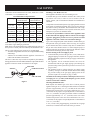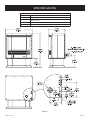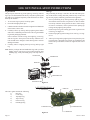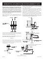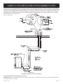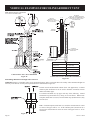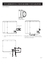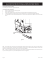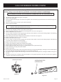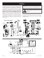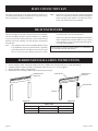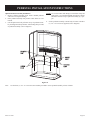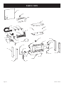
1
INSTALLATION INSTRUCTIONS
AND
OWNER’S MANUAL
EMPIRE
Comfort Systems
POWER-VENT
HIGH-EFFICIENCY
FIREPLACE WITH
BAY WINDOW
MODELS
PV-28SV50-(BN,BP)-1
PV-28SV55-(CN,CP,GN,GP)-1
Power
Humidifier
Burners
Rear
Exhaust
Fan
Blower
Mantis
Front
Hi
Med
Low
™
Installer:
Leave this
appliance.
Consumer: Retain this
reference.
manual
manual
with
the
for future
WARNING: If the information in these instructions are not followed exactly, a fire or explosion may result causing property damage,
personal injury or loss of life.
— Do not store or use gasoline or other flammable vapors and liquids in the vicinity of this or
any other appliance.
— WHAT TO DO IF YOU SMELL GAS
• Do not try to light any appliance.
• Do not touch any electrical switch; do not
use any phone in your building.
• Immediately call your gas supplier from a
neighbor’s phone. Follow the gas supplier’s instructions.
• If you cannot reach your gas supplier, call
the fire department.
— Installation and service must be performed
by a qualified installer, service agency or the
gas supplier.
This appliance is NOT to be installed in Canada.
This appliance may be installed in an aftermarket,
permanently located, manufactured home (USA
only) or mobile home, where not prohibited by
state or local codes.
This appliance is only for use with the type of gas
indicated on the rating plate. This appliance is
not convertible for use with other gases, unless a
certified kit is used.
WARNING: If not installed, operated and maintained in accordance with the manufacturer’s instructions, this product could expose you to substances in fuel or from fuel combustion which can
cause death or serious illness.
Page 1
TABLE OF CONTENTS
SECTION
PAGE
Important Safety Information ......................................................................................................................................... 3
Safety Information for Users of LP-Gas ......................................................................................................................... 4
Requirements for Massachusetts ..................................................................................................................................... 5
Gas Supply ...................................................................................................................................................................... 6
Introduction ..................................................................................................................................................................... 7
Installation Instructions – General Safety Information ................................................................................................... 8
Specifications .................................................................................................................................................................. 8
Clearances for Direct Vent .............................................................................................................................................. 9
Heater Installation for Direct Vent .................................................................................................................................. 9
Clearances for Single Flue ............................................................................................................................................ 10
Heater Installation for Single Flue ................................................................................................................................ 10
Specifications ........................................................................................................................................................ 11 – 14
Clearance to Combustibles ........................................................................................................................................... 15
Rough Framing Dimensions ......................................................................................................................................... 16
Insert Into Masonry Fireplace ....................................................................................................................................... 16
Wall Clearances ............................................................................................................................................................. 17
Log Set Installation Instructions ................................................................................................................................... 18
Vent Examples for Single Flue .............................................................................................................................. 19 - 21
PVVK-CFA Flex Vent Kit ............................................................................................................................................. 22
PVVK-SH Horizontal Vent Adaptor Kit ....................................................................................................................... 23
Horizontal Examples for Colinear Direct Vent ............................................................................................................. 24
Vertical Examples for Colinear Direct Vent ........................................................................................................... 25 - 26
PVCA Horizontal Colinear Direct Vent Adaptor .......................................................................................................... 27
PVVTC Termination Cap Vent Kit ............................................................................................................................... 28
PVCT Colinear Transition Vent Kit .............................................................................................................................. 29
Direct Vent Installation Instructions ...................................................................................................................... 30 - 31
PVVK-24H and PVVK-48H Vent Kit ................................................................................................................... 32 - 33
Gas Connection Installation Instructions ...................................................................................................................... 34
Operating Instructions Checklist ................................................................................................................................... 35
Lighting Instructions .............................................................................................................................................. 36 - 37
Fan Operation ................................................................................................................................................................ 38
Gas Conversion Instructions .................................................................................................................................. 39 - 40
Automatic Humidifier Operation .................................................................................................................................. 41
Optional Controllers................................................................................................................................................ 42 - 43
Wiring ........................................................................................................................................................................... 44
General Information ...................................................................................................................................................... 45
Maintenance ........................................................................................................................................................... 45 - 46
Unit Operating Faults .................................................................................................................................................... 47
Resetting the Heater ...................................................................................................................................................... 47
Log Placement .............................................................................................................................................................. 47
Main Convection Fan .................................................................................................................................................... 48
Heat Exchanger ............................................................................................................................................................. 48
Surround Installation Instructions ................................................................................................................................. 48
Pedestal Installation Instructions .................................................................................................................................. 49
Parts List ................................................................................................................................................................ 50 - 51
Parts View .............................................................................................................................................................. 52 - 53
Warranty Terms ............................................................................................................................................................. 54
How To Order Repair Parts ........................................................................................................................................... 55
Service Notes ......................................................................................................................................................... 55 - 56
Page 2
22618-17-0308
IMPORTANT SAFETY INFORMATION
THIS IS A HEATING APPLIANCE
DO NOT OPERATE THIS APPLIANCE WITHOUT FRONT PANEL INSTALLED.
•
Due to high temperatures the appliance should be located out of traffic and away from furniture and draperies.
•
Children and adults should be alerted to the hazards
of high surface temperatures and should stay away to
avoid burns or clothing ignition.
•
Young children should be carefully supervised when
they are in the same room as the appliance.
•
Clothing or other flammable material should not be
placed on or near the appliance.
•
Any safety screen or guard removed for servicing an appliance must be replaced prior to operating the appliance.
•
Keep burner and control compartment clean.
•
Vent cap hot while furnace is in operation.
•
For manufactured home (USA only) or mobile home or
residential installation convertible for use with natural gas and liquefied petroleum gases when provision
is made for the simple conversion from one gas to the
other.
22618-17-0308
•
Installation and repair should be done by a QUALIFIED SERVICE PERSON. The appliance should be inspected before use and at least annually by a qualified
service person. More frequent cleaning may be required
due to excessive lint from carpeting, bedding materials,
etc. It is imperative that control compartments, burners
and circulating air passageways of the appliance be kept
clean.
•
DO NOT put anything around the furnace that will obstruct the flow of combustion and ventilation air.
•
DO keep the appliance area clear and free from combustible material, gasoline and other flammable vapors and
liquids.
•
Do examine venting system periodically and replace
damaged parts.
•
Do make a periodic visual check of burner. Clean and
replace damaged parts.
•
DO NOT use this heater if any part has been under water. Immediately call a qualified service technician to inspect the heater and to replace any part of the control
system and any gas control which has been under water.
Page 3
SAFETY INFORMATION FOR USERS OF LP-GAS
Propane (LP-Gas) is a flammable gas which can cause fires and
explosions. In its natural state, propane is odorless and colorless.
You may not know all the following safety precautions which can
protect both you and your family from an accident. Read them
carefully now, then review them point by point with the mem-
bers of your household. Someday, there may not be a minute to
lose, everyone’s safety will depend on knowing exactly what to
do. If, after reading the following information, you feel you still
need more information, please contact your gas supplier.
LP-GAS WARNING ODOR
If a gas leak happens, you should be able to smell the gas because of the odorant put in the LP-Gas.
That’s your signal to go into immediate action!
•
•
•
•
Do not operate electric switches, light matches, use your
phone. Do not do anything that could ignite the gas.
Get everyone out of the building, vehicle, trailer, or area. Do
that IMMEDIATELY.
Close all gas tank or cylinder supply valves.
LP-Gas is heavier than air and may settle in low areas such
as basements. When you have reason to suspect a gas leak,
keep out of basements and other low areas. Stay out until
firefighters declare them to be safe.
•
•
Use your neighbor’s phone and call a trained LP-Gas service person and the fire department. Even though you may
not continue to smell gas, do not turn on the gas again. Do
not re-enter the building, vehicle, trailer, or area.
Finally, let the service man and firefighters check for escaped gas. Have them air out the area before you return.
Properly trained LP-Gas service people should repair the
leak, then check and relight the gas appliance for you.
NO ODOR DETECTED - ODOR FADE
Some people cannot smell well. Some people cannot smell the
odor of the chemical put into the gas. You must find out if you
can smell the odorant in propane. Smoking can decrease your
ability to smell. Being around an odor for a time can affect your
sensitivity or ability to detect that odor. Sometimes other odors
in the area mask the gas odor. People may not smell the gas odor
or their minds are on something else. Thinking about smelling a
gas odor can make it easier to smell.
The odorant in LP-gas is colorless, and it can fade under some
circumstances. For example, if there is an underground leak, the
movement of the gas through soil can filter the odorant. Odorants
in LP-Gas also are subject to oxidation. This fading can occur if
there is rust inside the storage tank or in iron gas pipes.
The odorant in escaped gas can adsorb or absorb onto or into
walls, masonry and other materials and fabrics in a room. That
will take some of the odorant out of the gas, reducing its odor
intensity.
LP-Gas may stratify in a closed area, and the odor intensity could
vary at different levels. Since it is heavier than air, there may be
more odor at lower levels. Always be sensitive to the slightest
gas odor. If you detect any odor, treat it as a serious leak. Immediately go into action as instructed earlier.
SOME POINTS TO REMEMBER
•
•
•
•
Learn to recognize the odor of LP-gas. Your local LP-Gas
Dealer can give you a “Scratch and Sniff” pamphlet. Use it
to find out what the propane odor smells like. If you suspect
that your LP-Gas has a weak or abnormal odor, call your
LP-Gas Dealer.
If you are not qualified, do not light pilot lights, perform service, or make adjustments to appliances on the LP-Gas system. If you are qualified, consciously think about the odor of
LP-Gas prior to and while lighting pilot lights or performing
service or making adjustments.
Sometimes a basement or a closed-up house has a musty
smell that can cover up the LP-Gas odor. Do not try to light
pilot lights, perform service, or make adjustments in an area
where the conditions are such that you may not detect the
odor if there has been a leak of LP-Gas.
Odor fade, due to oxidation by rust or adsorption on walls
of new cylinders and tanks, is possible. Therefore, people
should be particularly alert and careful when new tanks or
cylinders are placed in service. Odor fade can occur in new
tanks, or reinstalled old tanks, if they are filled and allowed
Page 4
•
•
to set too long before refilling. Cylinders and tanks which
have been out of service for a time may develop internal
rust which will cause odor fade. If such conditions are suspected to exist, a periodic sniff test of the gas is advisable. If
you have any question about the gas odor, call your LP-gas
dealer. A periodic sniff test of the LP-gas is a good safety
measure under any condition.
If, at any time, you do not smell the LP-Gas odorant and
you think you should, assume you have a leak. Then take
the same immediate action recommended above for the occasion when you do detect the odorized LP-Gas.
If you experience a complete “gas out,” (the container is under no vapor pressure), turn the tank valve off immediately.
If the container valve is left on, the container may draw in
some air through openings such as pilot light orifices. If this
occurs, some new internal rusting could occur. If the valve is
left open, then treat the container as a new tank. Always be
sure your container is under vapor pressure by turning it off
at the container before it goes completely empty or having it
refilled before it is completely empty.
22618-17-0308
REQUIREMENTS FOR MASSACHUSETTS
For all side wall horizontally vented gas fueled equipment installed
in every dwelling, building or structure used in whole or in part
for residential purposes, including those owned or operated by the
Commonwealth and where the side wall exhaust vent termination
is less than seven (7) feet above finished grade in the area of
the venting, including but not limited to decks and porches, the
following requirements shall be satisfied:
1.
INSTALLATION OF CARBON MONOXIDE DETECTORS.
At the time of installation of the side wall horizontal vented
gas fueled equipment, the installing plumber or gas fitter shall
observe that a hard wired carbon monoxide detector with an
alarm and battery back-up is installed on the floor level where
the gas equipment is to be installed. In addition, the installing
plumber or gas fitter shall observe that a battery operated
or hard wired carbon monoxide detector with an alarm is
installed on each additional level of the dwelling, building or
structure served by the side wall horizontal vented gas fueled
equipment. It shall be the responsibility of the property owner
to secure the services of qualified licensed professionals for
the installation of hard wired carbon monoxide detectors
a. In the event that the side wall horizontally vented gas
fueled equipment is installed in a crawl space or an attic,
the hard wired carbon monoxide detector with alarm and
battery back-up may be installed on the next adjacent
floor level.
b. In the event that the requirements of this subdivision can
not be met at the time of completion of installation, the
owner shall have a period of thirty (30) days to comply
with the above requirements; provided, however, that
during said thirty (30) day period, a battery operated
carbon monoxide detector with an alarm shall be
installed.
2.
APPROVED CARBON MONOXIDE DETECTORS. Each
carbon monoxide detector as required in accordance with the
above provisions shall comply with NFPA 720 and be ANSI/
UL 2034 listed and IAS certified.
22618-17-0308
3.
SIGNAGE. A metal or plastic identification plate shall be
permanently mounted to the exterior of the building at a
minimum height of eight (8) feet above grade directly in line
with the exhaust vent terminal for the horizontally vented gas
fueled heating appliance or equipment. The sign shall read,
in print size no less than one-half (1/2) inch in size, “GAS
VENT DIRECTLY BELOW. KEEP CLEAR OF ALL
OBSTRUCTIONS”.
4.
INSPECTION. The state or local gas inspector of the side
wall horizontally vented gas fueled equipment shall not
approve the installation unless, upon inspection, the inspector
observes carbon monoxide detectors and signage installed
in accordance with the provisions of 248 CMR 5.08(2)(a) 1
through 4.
(b) EXEMPTIONS: The following equipment is exempt
from 248 CMR 5.08(2)(a)1 through 4:
1. The equipment listed in Chapter 10 entitled
“Equipment Not Required To Be Vented” in the
most current edition of NFPA 54 as adopted by the
Board; and
2. Product Approved side wall horizontally vented gas
fueled equipment installed in a room or structure
separate from the dwelling, building or structure
used in whole or in part for residential purposes.
(d) MANUFACTURER REQUIREMENTS - GAS
EQUIPMENT VENTING SYSTEM NOT PROVIDED.
When the manufacturer of a Product Approved side
wall horizontally vented gas fueled equipment does not
provide the parts for venting the flue gases, but identifies
“special venting systems”, the following requirements
shall be satisfied by the manufacturer:
1. The referenced “special venting system” instructions
shall be included with the appliance or equipment
installation instructions; and
2. The “special venting systems” shall be Product
Approved by the Board, and the instructions for
that system shall include a parts list and detailed
installation instruction.
(e) A copy of all installation instructions for all Product
Approved side wall horizontally vented gas fueled
equipment, all venting instructions, all parts lists for
venting instructions, and/or all venting design instructions
shall remain with the appliance or equipment at the
completion of the installation.
Page 5
GAS SUPPLY
Consult the current National Fuel Gas Code, ANSI Z223.1 CAN/
CGA-B149 (.1 or .2) installation code.
Installing a New Main Gas Cock
Each appliance should have its own manual gas cock.
Recommended Gas Pipe Diameter
Pipe Length
Schedule 40 Pipe
Tubing, Type L
Inside Diameter
Outside Diameter
Nat.
L.P.
Nat.
L.P.
0-10 feet
1/2”
3/8”
1/2”
3/8”
0-3 meters
12.7mm 9.5 mm 12.7mm 9.5 mm
10-40 feet
1/2”
1/2”
5/8”
1/2”
4-12 meters 12.7mm 12.7mm 15.9 mm 12.7mm
40-100 feet
1/2”
1/2”
3/4”
1/2”
13-30 meters 12.7mm 12.7mm
19mm 12.7mm
100-150 feet
3/4”
1/2”
7/8”
3/4”
31-46 meters 19mm 12.7mm 22.2 mm 19mm
A manual main gas cock should be located in the vicinity of the
unit. Where none exists, or where its size or location is not adequate, contact your local authorized installer for installation or
relocation.
Note: Never use plastic pipe. Check to confirm whether your local
codes allow copper tubing or galvanized.
Note: Since some municipalities have additional local codes, it is
always best to consult your local authority and installation code.
The use of the following gas connectors is recommended:
— ANS Z21.24 Appliance Connectors of Corrugated Metal Tubing
and Fittings
— ANS Z21.45 Assembled Flexible Appliance Connectors of
Other Than All-Metal Construction
The above connectors may be used if acceptable by the authority
having jurisdiction. The state of Massachusetts requires that a flexible
appliance connector cannot exceed three feet in length.
A gas valve and ground joint union should be installed in the gas
line upstream of the gas control to aid in servicing. It is required
by the National Fuel Gas Code that a drip line be installed near
the gas inlet. This should consist of a vertical length of pipe tee
connected into the gas line that is capped on the bottom in which
condensation and foreign particles may collect.
Pressure Testing of the Gas Supply System
1. To check the inlet pressure to the gas valve, a 1/8" (3 mm) N.P.T.
plugged tapping, accessible for test gauge connection, must be
placed immediately upstream of the gas supply connection to
the appliance.
2. The appliance and its individual shutoff valve must be
disconnected from the gas supply piping system during any
pressure testing of that system at test pressures in excess of 1/2
psig (3.5 kPa).
3. The appliance must be isolated from the gas supply piping
system by closing its individual manual shutoff valve during
any pressure testing of the gas supply piping system at test
pressures equal to or less than 1/2 psig (3.5 kPa).
FLARE FITTING
FLARE SHUT OFF VALVE
SOLENOID
GAS VALVE
3/8 NPT
NIPPLE
Figure 1
FLEX TUBING
Compounds used on threaded joints of gas piping shall be resistant
to the action of liquefied petroleum gases. The gas lines must be
checked for leaks by the installer. This should be done with a soap
solution watching for bubbles on all exposed connections, and if
unexposed, a pressure test should be made.
Never use an exposed flame to check for leaks. Appliance must
be disconnected from piping at inlet of control valve and pipe
capped or plugged for pressure test. Never pressure test with
appliance connected; control valve will sustain damage!
Attention! If one of the procedures results in pressures in excess
of 1/2 psig (14" w.c.) (3.5 kPa) on the fireplace gas valve, it will
result in a hazardous condition.
Checking Manifold Pressure
Both Propane and Natural gas valves have a built-in pressure
regulator in the gas valve. Natural gas models will have a manifold
pressure of approximately 3.5" w.c. (.872 kPa) at the valve outlet
with the inlet pressure to the valve from a minimum of 5.0" w.c.
(1.245 kPa) for the purpose of input adjustment to a maximum of
10.5" w.c. (2.614 kPa) Propane gas models will have a manifold
pressure approximately 7.0" w.c. (2.49 kPa) at the valve outlet
with the inlet pressure to the valve from a minimum of 11.0" w.c.
(2.739 kPa) for the purpose of input adjustment to a maximum of
13.0" w.c. (3.237 kPa).
A 1/8" (3 mm) N.P.T. plugged tapping, accessible for test gauge
connection, is located on the outlet side of the gas control.
Page 6
22618-17-0308
INTRODUCTION
Introduction
Always consult your local Building Department regarding regulations, codes or ordinances which apply to the installation of a
direct vent wall furnace.
Instructions to Installer
1. Installer must leave instruction manual with owner after installation.
2. Installer must have owner fill out and mail warranty card supplied with furnace.
3. Installer should show owner how to start and operate furnace
and thermostat.
4. Installer must locate unit near a grounded wall receptacle for
115VAC power and must provide gas supply and vent the
unit properly for safe operation.
Warning:
Any change to this furnace or its control can be dangerous.
This is a heating appliance and any panel, door or guard
removed for servicing an appliance must be replaced prior
to operating the appliance.
General Information
This series is designed certified in accordance with American
National Standard/CSA Standard Z21.88 and CSA 2.33 by the
Canadian Standards Association as a Gas Fireplace Heater to be
installed according to these instructions.
Any alteration of the original design, installed other than as
shown in these instructions or use with a type of gas not shown
on the rating plate is the responsibility of the person and company making the change.
Important
All Correspondence should refer to complete Model Number, Serial Number and type of gas.
Notice: During initial firing of this unit, oil from the heat exchanger may bake out and smoke may occur. To prevent triggering of
smoke alarms, ventilate the room in which the unit is installed.
Installation in Residential Garages
Gas utilization equipment in residential garages shall be installed
so that all burners and burner ignition devices are located not less
than 18” (457 mm) above the floor.
Qualified Installing Agency
Installation and replacement of gas piping, gas utilization equipment or accessories and repair and servicing of equipment shall be
performed only by a qualified agency. The term “qualified agency” mean any individual, firm, corporation or company which
either in person or through a representative is engaged in and is
responsible for (a) the installation or replacement of gas piping or
(b) the connection, installation, repair or servicing of equipment,
who is experienced in such work, familiar with all precautions required and has complied with all the requirements of the authority
having jurisdiction.
The installation must conform with local codes, or in the absence
of local codes, the National Fuel Gas Code, ANSI Z223.1/NFPA
54 or Natural Gas and Propane Installation Code, CSA B149.1.
* Available from the American National Standards Institute, Inc.,
11 West 42nd St., New York, NY 10036.
A manufactured home (USA only) or mobile home OEM installation must conform with the Manufactured Home Construction
and Safety Standard, Title 24 CFR, Part 3280, or, when such a
standard is not applicable, the Standard for Manufactured Home
Installations, ANSIZ225.1, or Standard for Gas Equipped Recreational Vehicles and Mobile Housing, CSA Z240.0.
Sate of Massachusetts: The installation must be made by a
licensed plumber or gas fitter in the Commonwealth of Massachusetts.
High Altitudes
For altitudes/elevations above 2,000 feet (610 m), input ratings
should be reduced at the rate of 4 percent for each 1,000 feet (305
m) above sea level, this may be accomplished by reducing manifold pressure. The maximum allowable reduction in manifold
pressure for Natural gas shall be from 3.5” w.c. (.872 kPa) to 2.8”
w.c. (.697 kPa). The maximum allowable reduction in manifold
pressure for Propane (LP) gas shall be from 10.0” w.c. (2.49 kPa)
to 8.0” w.c. (1.99 kPa). For Canadian high altitude applications,
this appliance is suitable for installation at elevations between 0
feet (0 m) and 4,500 feet (1,372 m) without change.
Canada:
This appliance is NOT to be installed in Canada.
Such equipment shall be located, or protected, so it is not subject
to physical damage by a moving vehicle.
22618-17-0308
Page 7
INSTALLATION INSTRUCTIONS - GENERAL SAFETY INFORMATION
1.
This installation must conform with local codes or, in the absence of local codes with NFPA54.
2.
Provide adequate clearances around the product for servicing and ensure there are no obstructions to the combustion
air intake situated at the back of the heater. Refer to Page 15,
Figures 7 through 10.
3.
The appliance must be installed on a flat, solid continuous
surface (i.e. wood, metal, concrete). Please Note: Rough or
uneven surfaces can cause vibration or humming in the heater.
4.
The Mantis Power-Vent High-Effeciency Fireplace can be installed in a wide variety of ways and will fit nearly any room
layout. It may be installed in a recessed position, framed out
into the room, or across a corner. For installation options refer to page 15.
5.
This appliance (Insert and Freestanding Models) needs to be
installed in such a way that the heater can be removed at all
times to service the heater exchanger and flue fan located in
the rear section of the heater.
Note:
Under no circumstances should the appliance be installed under conditions which would not allow for
easy removal of the appliance to carry out routine
inspection and service to the appliance, to do so will
void the warranty.
Note:
On Single Wall flue pipe installations (imitation zero
clearance fireplace) a minimum of 2” (50.8 cm) clearance must be provided at the rear of the heater to enable
the heater to get sufficient combustion air to the air inlet
located at the rear of heater. Refer to installation instructions on page 15, Figures 7 through 10.
Note:
Where a mantel surround is being used on insert installations and zero clearance fireplace installations, the combustion air intake slot located in the top mantel surround
must have no obstructions to allow combustion air to enter through the slot to the combustion air inlet located at
the back of the heater.
SPECIFICATIONS
Model
PV28SV50
Input BTU/HR (KW/H)
19,000 Rear - 9,000 Front
Height
25 1/8”
28 3/16”
Width
Depth
17 5/8”
Gas Inlet (Pipe)
3/8” Flair
Electrical - Unit has a 5’ (1.5 m) 3 pronged cordset for connection to an approved 115 VAC 60 Hz maximum
AMPs - 5A wall receptacle.
Page 8
Accessories
Part Number
Description
PV-2H
Top Cover - Slim Assembly
PV-4H
Top Cover - Short Assembly
PVPK
Pedestal Kit
PVE-1
6” Surround Assembly
PVSH
Rear Shroud
TRW
Wall Thermostat - Wireless Remote
FRBTC
Battery Operated Remote w/Thermostat
FRBTP
Battery Operated Remote w/Programmable Thermostat
TMV2
Two-Stage Thermostats
CIPFP-1
Floor Pad Kit
CIFPB-1C
Corner Floor Pad Kit
PVVK24H
Direct Vent 24” Vent Kit
PVVK48H
Direct Vent 48” Vent Kit
PVVK-SH
Single Flue Horizontal Vent Kit
PVVK-SV
Single Flue Vertical Vent Kit
PVVK-CFA
Flex Vent Kit
PVCT
Colinear Transition
PVVTC
Vertical Termination Cap - 1.5”
PVCA
Colinear Adapter
22618-17-0308
CLEARANCES FOR DIRECT VENT
1.
Pick a location on a wall with a clear space in the room. In
selecting a location for installation, it is necessary to provide
adequate accessibility clearances for servicing and proper
installation. Be sure to locate the unit close enough to a 110
VAC wall receptacle to properly power appliance.
2.
When facing the front of the furnace the minimum clearances
from casing to combustible construction are 0” (0 mm) on top,
0” (0 mm) on each side, recommend 4” (102 mm) on sides
for servicing and 0” (0 mm) from the floor, 0” (0 mm) to rear
wall and 40” (1,016 mm) from Mantis top to ceiling.
3.
The minimum distance from the center of the vent cap to the
nearest outside corner or obstruction is 12” (305 mm).
4.
The minimum wall depth is 4” (102 mm) and the maximum
is 48” (121.92 cm).
The vent terminal of a direct vent appliance, with an input of
50,000 BTU (14.6KW) per hour or less shall be located at least
9” (229 mm) from any opening through which flue gases could
enter a building.
The bottom of the exhaust vent terminal and the air intake shall
be located at least 12” (305 mm) above grade and must be vented
outside.
WARNING: The nearest point of the vent cap should be
a minimum horizontal distant of six (6) feet (1.83 m) from
any pressure regulator. In case of regulator malfunction,
the six (6) feet (1.83 m) distance will reduce the chance of
gas entering the vent cap.
Installation on Rugs and Tile
If this appliance is to be installed directly on carpeting, tile, or other
combustible material, other than wood flooring, the appliance shall
be installed on a metal or wood panel extending the full width and
depth of the appliance.
The base referred to above does not mean the fire-proof base as
used on wood stoves. The protection is primarily for rugs that may
be extremely thick and light-color tile that can discolor.
HEATER INSTALLATION FOR DIRECT VENT
Locating Wall Opening
The recommended location for this furnace is on an outside wall.
Locate wall studs so that wall vent opening will be located between
wall studs. The wall opening required for venting is a 3 1/2” (89
mm) minimum diameter opening.
Refer to Figures 3 and 6 for positioning the heater on wall and for
locating gas line connection and vent opening. Furnace can sit on
the floor.
1 9/16”
4 3/32”
Figure 2
22618-17-0308
Page 9
CLEARANCES FOR SINGLE FLUE
1.
2.
3.
Pick a location on a wall with a clear space in the room. In
selecting a location for installation, it is necessary to provide
adequate accessibility clearances for servicing and proper
installation. Be sure to locate the unit close enough to a 115
VAC wall receptacle to properly power appliance.
When facing the front of the furnace, the minimum clearances
from casing to combustible construction are 0” (0 mm) on top,
0” (0 mm) on each side, recommend 4” (102 mm) for servicing
and 0” (0 mm) from the floor and 2” (51 mm) to rear wall for
servicing and installation.
The minimum distance from the center of the vent cap to the
nearest outside corner or obstruction is 12” (305 mm).
The bottom of the exhaust vent terminal and the air intake shall
be located at least 12” (305 mm) above grade and must be vented
outside.
WARNING: The nearest point of the vent cap should be a
minimum horizontal distance of six (6) feet (1.83 m) from
any pressure regulator. In case of regulator malfunction,
the six (6) feet (1.83 m) distance will reduce the chance of
gas entering the vent cap.
Installation on Rugs and Tile
If this appliance is to be installed directly on carpeting, tile, or other
combustible material, other than wood flooring, the appliance shall
be installed on a metal or wood panel extending the full width and
depth of the appliance.
The base referred to above does not mean the fire-proof base as
used on wood stoves. The protection is primarily for rugs that may
be extremely thick and light-color tile that can discolor.
HEATER INSTALLATION FOR SINGLE FLUE
Locating Wall Opening
The recommended location for this heater is on an outside wall (the
unit can be located on an inside wall but must not exceed 40’ (12.19
m) in exhaust vent length). Locate wall studs so that wall vent opening
will be located between wall studs. The wall opening required for
venting is a 1 7/8” (48 mm) minimum diameter opening.
Refer to Figures 3 to 6 for positioning the heater on wall and for
locating gas line connection and vent opening. Heater can sit on
the floor.
Page 10
22618-17-0308
SPECIFICATIONS
1
2
3
4
5
Heater with Pedestal and Single Flue Adaptor
Flue Outlet 1 1/2” PVC Pipe
Air Inlet
Electric Cord
3/8” Flare Connection (Inside)
Single Flue Adaptor Model #PVVK-SH (required)
Figure 3
22618-17-0308
Page 11
SPECIFICATIONS - (continued)
1
2
3
4
5
Heater without pedestal
Flue Outlet 1 1/2” PVC Pipe
Air Inlet
Electric Cord
3/8” Flare Connection (Inside)
Single Flue Adaptor Model #PVVK-SH (required)
Figure 4
Page 12
22618-17-0308
SPECIFICATIONS - (continued)
Fireplace Insert with Mantel Surround with Slim Top Panel
1
Flue Outlet 1 1/2” PVC Pipe
2
Air Inlet
3
Electric Cord
4
3/8” Flare Connection (Inside)
5
Single Flue Adaptor Model #PVVK-SH (Required)
6
Surround Model #PVE-1
7
Top Cover Kit, Slim Model #PV2H
Caution: Do not block louver in surround.
Note: Verify fireplace opening dimensions using Figure 9, page 15.
Figure 5
22618-17-0308
Page 13
SPECIFICATIONS - (continued)
1
2
3
4
5
6
8
Fireplace Insert with Mantel Surround with Short Top Panel
Flue Outlet 1 1/2” PVC Pipe
Air Inlet
Electric Cord
3/8” Flare Connection (Inside)
Single Flue Adaptor Model #PVVK-SH (Required)
Surround Model #PVE-1
Top Cover Kit, Short Model #PV4H
Caution: Do not block louver in surround.
Note: Verify fireplace opening dimensions using Figure 9, page 15.
Figure 6
Page 14
22618-17-0308
CLEARANCE TO COMBUSTIBLES
Freestanding Models
A
B
B
C
Figure 7
A
B
C
D
Rear Wall to Heater
Side Wall to Heater
Corner Installation
Mantel Clearance
C
Figure 8
Freestanding Units
0” (2” Single Flue and 1 1/4” Direct Vent for Serviceability)
0” (4” recommended for serviceability)
0”
See Figure 11
Fireplace Insert
CEILING
8”
6”
COMBUSTIBLE TRIM AND MANTELS
ALLOWED IN SHADED AREA
40”
4”
24”
18”
Single Flue
Requires surround for combustion air.
Do not cover surround louver.
Figure 9
Direct Vent Installation Shown
Single Flue requires surround for combustion air.
Figure 10
Note:
12”
Mantel and Ceiling Clearances
Figure 11
The Mantis Power-Vent High-Efficiency Fireplace has been tested and approved for zero clearance to combustible materials.
Empire Comfort Systems, Inc. recommends that clearances as listed above should be maintained to allow for removal of the
product for servicing.
22618-17-0308
Page 15
ROUGH FRAMING DIMENSIONS
A
-
13 /34” MIN. CO-LINEAR
8 1/2” WHEN USING DIRECT VENTING
PVVK-24H/PVVK-48H
NOTE: DIMENSIONS FOR USE WITH SHORT TOP
PV4H. THIS IS RECOMMENDED FOR UNIT
SERVICEABILITY.
B
-
25 1/8”
C
-
28”
NOTE: IF TRIM AROUND HEATER IS NECESSARY,
THE SURROUND KIT PVE-1 MUST BE USED,
AND SUBTRACT 1” FROM (A) DIMENSION.
Figure 12
INSERT INTO MASONRY FIREPLACE
A
-
12 3/4” MIN. SHORT TOP PV4H
17 13/16” MIN. SLIM TOP PV2H
USING PVE-1 SURROUND KIT
B
-
25 1/8” MIN. DIRECT VENT
26 1/2” MIN. SINGLE FLUE
29” MAX
C
-
28” MIN. NO SURROUND
33” MIN. WITH PVE-1 SURROUND
35” MAX. WITH PVE-1 SURROUND
Figure 13
Page 16
22618-17-0308
WALL CLEARANCES
Figure 14
22618-17-0308
Page 17
LOG SET INSTALLATION INSTRUCTIONS
Log Installation
The gas log set (front left log, front right log, center log and rear
log) is pre-set and installed in the factory. Only the top left log and
top right log are packaged separately inside the firebox for installation by the installer.
1.
To access the log set parcel, lift off top panel.
2.
Pivot left and right panels open.
3.
Unlatch main door latches located on right and left hand side
of the heater, remove door.
4.
Carefully remove top left log and top right log from firebox
and remove cardboard protection from center log and middle
log and all packaging materials.
Note: Positions of front left log, front right log, center log,
and rear log have been preset at the factory and their locations should not be changed. Check that logs have not been
damaged in transit.
5.
All Logs
The positioning of the logs is critical to the safe and clean operation of this heater. Sooting and other problems may result if the
logs are not properly and firmly positioned in the appliance.
6.
Prior to positioning of top left log and top right log, inspect
front burner and rear burner for particles or dust accumulation on top of burners. If any particles or dust is visible on top
of front or rear burners, remove particles before placing top
left log and top right log into position.
7.
Position top left log into locating pin on rear log and rest on
center log. See Figure 15.
8.
Position top right log into locating slot on rear log. See Figure 15.
9.
After top left log and top right log have been placed in position and safety check has been carried out, install door and
latch securely with latches located on right and left side of
heater.
Carefully remove wrapping from top left log and top right
log.
Note: Before you begin: Do not handle these logs with your bare
hands! Always wear gloves to prevent skin irritation. After
handling logs, wash your hands gently with soap and water.
TOP LEFT LOG
TOP RIGHT LOG
REAR LOG
CENTER LOG
FRONT RIGHT LOG
FRONT LEFT LOG
Figure 15
LOG SET DIAGRAM - A
The Gas Log Kit contains the following:
1)
Rear Log
2)
Center Log
3)
Top Right Log
4)
Top Left Log
5)
Front Left Log
6)
Front Right Log
4 - TOP LEFT LOG
5 - FRONT LEFT LOG
Figure 16
Page 18
1 - REAR LOG
3 - TOP RIGHT LOG
6 - FRONT RIGHT LOG
2 - CENTER LOG
22618-17-0308
VENT EXAMPLES FOR SINGLE FLUE
Max Vent Run - 40 ft. Equivalent With Three (3) 90° Elbows
Special Note: The vent terminal 90° elbow and first 90° elbow off back of the heater, when within 6” (15.2 cm), do not contribute to the overall vent length measurement. For each 45° elbow installed in the horizontal run, the length of the horizontal run
MUST be reduced by 1.5 feet (45 cm). This does not apply if the 45° elbows are installed on the vertical part of the vent system.
Reduce the length of the horizontal run 3 feet (91.4 cm) for every 90° elbow.
Note: On horizontal runs, a P.V.C. support clamp needs to be installed every 3 feet. No “sags” in horizontal vent runs; water will settle
in the pipe.
When installing a single flue horizontal, the minimum vent length protruding from the outside wall is 6” (15.2 cm). See Figure 17.
Minimum vent from the rear of the unit is 12”.
Note: Horizontal discharge 90° elbow must be pointed downward. See Figure 18. All horizontal runs require either a 1/4” per foot rise
to run condensation back to the heater, or a 1/4” per foot downward slope to run condensation away from the heater.
Note: All PVC vent run piping can be purchased at a local hardware store. Schedule 40 PVC pipe should be used and cemented.
PVVK-CFA Flex Kit and PVVK-SH Horizontal Vent Adaptor Kit are available from Empire Comfort Systems, Inc.
MIN. 2”
12” MIN.
H=
V=
(2) - 90° =
Total =
5’ + 2’ = 7’
27’
6’
40’
6” MIN. 12” MIN.
EXTERIOR GRADE
Figure 17
Single Flue - Straight Out Back
Min 6” Outside Wall
Min 2” From Unit to Wall for Intake Air
Min vent length 12”
Figure 18
Single Flue - Horizontal Tall Vent Run
Example Calculation Max Vent Run 40’
22618-17-0308
Page 19
VENT EXAMPLES FOR SINGLE FLUE (cont.)
V=
Total =
40’
40’
Figure 20
Venting for Existing Fireplace Installation
H=
V=
(1) - 90° =
Total =
36’
1’
3’
40’
SINGLE FLUE ADAPTOR
MODEL #PVVK-SH
Figure 19
Single Flue - Vertical Vent Run
Page 20
Figure 21
Single Flue - Venting with Shroud Installed
Shroud Kit Model# PVSH
22618-17-0308
VENT EXAMPLES FOR SINGLE FLUE (cont.)
Figure 22
Minimum Exterior Grade Dimension - Single Flue, Horizontal Venting Below Floor
VENT CAP
(SUPPLIED WITH VENT KIT)
MODEL #PVVK-SV
H
FLASHING
12
X
2 - 45 DEG. PVC
BENDS (SUPPLIED
BY INSTALLER)
MANTEL
SURROUND
MODEL #PVE-1
ROOF PITCH
IS X
12
Determining Minimum Vent Height Above
the Roof
ROOF PITCH
H (Min.)
Flat to 6/12
12” (305 mm)
6/12 to 7/12
15” (381 mm)
Over 7/12 to 8/12
18” (457 mm)
Over 8/12 to 16/12
24” (610 mm)
Over 16/12 to 21/12
PVC PIPE
(SUPPLIED BY INSTALLER)
36” (914 mm)
FLEXIBLE PVC PIPE
WITH 1/2” COUPLING ON EACH END
MODEL #PVVK-CFA
GAS SUPPLY
Figure 23
Single Flue - Vertical Vent Run
with 45 degree elbows
WARNING: Major U.S. building codes specify minimum chimney and/or vent height above the rooftop. These minimum heights are
necessary in the interest of safety. These specifications are summarized in Figure 23.
22618-17-0308
Page 21
PVVK-CFA FLEX VENT KIT
Available from Empire Comfort Systems, Inc.
The flex vent kit is a flexible vent hose that is 42” in length. The flex vent kit will be used when installing a Mantis into an existing
fireplace. The flex vent kit can be cut down, but can only be cut from one end.
Cement PVC Joints
Cut End
Cement PVC Joints
Once length is determined, install two (2) 10 x 1/2” screws into the adaptor assembly to secure the adaptor assembly to the flex hose.
Using PVC cement, cement all PVC joints of the flex vent kit to the remaining PVC vent run.
Determining Minimum Vent Height Above the Roof
WARNING: Major U.S. building codes specify minimum chimney and/or vent height above the rooftop. These minimum heights are
necessary in the interest of safety.
VENT CAP (SUPPLIED
WITH VENT KIT)
GALV. SHEET FLASHING
TO SEAL CHIMNEY
(SUPPLIED BY INSTALLER)
PVC PIPE SWV
(SUPPLIED BY INSTALLER)
(2) - 45 DEG. PVC BENDS
(SUPPLIED BY INSTALLER
IF NECCESSARY)
CUT END
ROOF PITCH
Flat to 6/12
H (Min.)
12” (305 mm)
6/12 to 7/12
Over 7/12 to 8/12
Over 8/12 to 16/12
Over 16/12 to 21/12
15” (381 mm)
18” (457 mm)
24” (610 mm)
36” (914 mm)
FLEXIBLE
FLUE KIT
FLEXIBLE GAS
LINE
Venting for Existing Fireplace Installation
Page 22
22618-17-0308
PVVK-SH HORIZONTAL VENT ADAPTOR KIT
Available from Empire Comfort Systems, Inc.
INSTALL FOAM GASKET
FLUE ADAPTOR
Attach flue adaptor to back of heater with four (4) screws.
Note: No PVC cement is needed
to install flue adaptor kit.
PLASTIC GASKET
THREADED CONNECTOR
Install plastic gasket and screw threaded connector to the flue adaptor.
When these connections are made, continue with your vent run.
Cement all PVC joints on vent run.
22618-17-0308
Page 23
HORIZONTAL EXAMPLES FOR COLINEAR DIRECT VENT
Max Vent Run - 40 ft. Equivalent With Three (3) 90° Elbows
Special Note: The vent terminal 90° elbow and first 90° elbow
off back of the heater, when within 6” (15.2 cm), do not contribute to the overall vent length measurement. For each 45°
elbow installed in the horizontal run, the length of the horizontal run MUST be reduced by 1.5 feet (45 cm). This does
not apply if the 45° elbows are installed on the vertical part of
the vent system. Reduce the length of the horizontal run 3 feet
(91.4 cm) for every 90° elbow.
Note: On horizontal runs, a P.V.C. support clamp needs to be installed every 3 feet. No “sags” in horizontal vent runs; water will
settle in the pipe.
When installing a colinear horizontal, the minimum vent length
protruding from the outside wall is 6” (15.2 cm) for air intake and
9” for exhaust. See Figure 27.
Note: Horizontal discharge 90° elbow must be pointed downward. See Figure 26. All horizontal runs require either a 1/4” per
foot rise to run condensation back to the heater, or a 1/4” per foot
downward slope to run condensation away from the heater.
Note: All PVC vent run piping can be purchased at a local hardware store. Schedule 40 PVC pipe should be used and cemented.
PVCA Horizontal Colinear Direct Vent Adaptor, PVVTC Cap,
PVVK-CFA Flex Kit and PVVK-SH Horizontal Vent Adaptor Kit
are available from Empire Comfort Systems, Inc.
MIN. 2”
3” MIN.
6” MIN.
12” MIN.
9” MIN.
EXTERIOR GRADE
Figure 25
In both vertical and horizontal colinear direct vent applications,
a colinear transition plate model PVCT can be used to minimize
clearances between intake and exhaust pipes.
For horizontal colinear direct venting, exhaust and intake air, cap
pipes with 90º elbows, pointed downward.
Figure 24
Note: If transition plate (model PVCT) is used, the measurement
for center to center of the pipes will be 2.5”. If the transition plate
(model PVCT) is not used, the measurement for center to center
of the pipes can be 3” to 24” maximum.
Figure 26
Note: Must maintain a minimum 3” between
exhaust outlet and air intake.
Figure 27
Enhanced top view of Figure 26
Page 24
22618-17-0308
VERTICAL EXAMPLES FOR COLINEAR DIRECT VENT
Special Note: The vent terminal (PTrap, Vent cap or two 90° elbows) and first 90° elbow off back of the heater, when within 6”
(15.2 cm) off back of the heater, do not contribute to the overall vent length measurement. For each 45° elbow installed in the
horizontal run, the length of the horizontal run MUST be reduced by 1.5 feet (45 cm). This does not apply if the 45° elbows are
installed on the vertical part of the vent system. Reduce the length of the horizontal run 3 feet (91.4 cm) for every 90° elbow.
Note: Exhaust must be a minimum of 3”
above air intake inlet.
Figure 28
Calculation example of vent run maximum 40’
Determining Minimum Vent Height Above the Roof
WARNING: Major U.S. building codes specify minimum chimney and/or vent height above the rooftop. These minimum heights are
necessary in the interest of safety.
22618-17-0308
Page 25
VERTICAL EXAMPLES FOR COLINEAR DIRECT VENT
Note: Exhaust must be a minimum
of 3” above air intake inlet.
EXHAUST
TERMINATION CAP
MODEL PVVTC, PTRAP
OR 2 90° ELBOWS
AIR INTAKE
PTRAP, 2 90° ELBOWS (SUPPLIED
BY INSTALLER) OR TERMINATION CAP
MODEL PVVTC. PTRAP TO FACE
AWAY FROM ROOF.
3” - 24”
HEIGHT
HEIGHT
FLASHING
REQUIRED
OPTION
12
X
CO-LINEAR
DIRECT VENT ADAPTER
MODEL PVCA
SINGLE FLUE
MODEL PVVK-SH
Colinear Direct Vent - Insert Installation
Figure 29
Determining Minimum Vent Height Above the Roof
ROOF PITCH
H (Min.)
Flat to 6/12
12” (305 mm)
6/12 to 7/12
15” (381 mm)
Over 7/12 to 8/12
18” (457 mm)
Over 8/12 to 16/12
24” (610 mm)
Over 16/12 to 21/12
36” (914 mm)
Colinear Direct Vent - Pitched Roof Installation
Figure 30
WARNING: Major U.S. building codes specify minimum chimney and/or vent height above the rooftop. These minimum heights are
necessary in the interest of safety. These specifications are summarized in Figure 30.
In both vertical and horizontal colinear direct vent applications, a colinear
transition plate model PVCT can be used to minimize clearances between
intake and exhaust pipes.
For exhaust and intake air, cap pipes with any of the following: Vertical
termination cap (model #PVVTC), PTrap, or two 90º elbows. When transition plate (model PVCT) is used, two termination caps (model PVVTC) may
NOT be used.
Note: If transition plate (model PVCT) is used, the measurement for center
to center of the pipes will be 2.5”. If the transition plate (model PVCT) is
not used, the measurement for center to center of the pipes can be 3” to 24”
maximum.
Figure 31
Page 26
22618-17-0308
PVCA HORIZONTAL COLINEAR DIRECT VENT ADAPTOR
Colinear adaptor to be used in conjunction with single flue horizontal vent kit PVVK-SH. The two attachments are used for colinear
direct vent installation.
Colinear adaptor
COLINEAR ADAPTER
1.
Attach colinear adaptor to back of heater with two (2)
screws.
2.
When adapter is connected, continue with your vent run.
Cementing PVC joint is recommended, but not required on
colinear fresh air intake adaptor.
3 15/16”
7 9/16”
4 13/16”
6 1/8”
22618-17-0308
Page 27
PVVTC TERMINATION CAP VENT KIT
Available from Empire Comfort Systems, Inc.
Termination Cap
PVC CEMENT
Vertical exhaust cap used with 1 1/2” PVC pipe installation.
Termination cap also used with colinear transition plate model PVCT.
Refer to instruction manual for venting examples.
Page 28
22618-17-0308
PVCT COLINEAR TRANSITION VENT KIT
Available from Empire Comfort Systems, Inc.
Colinear Transition Plate
Note: Exhaust must be a minimum of 3” above air intake inlet.
EXHAUST
PTRAP OR 2 90° ELBOWS
SUPPLIED BY INSTALLER
OPTIONAL EXHAUST CAP
MODEL PVVTC
ORDER SEPARATE
AIR INTAKE
PTRAP OR 2 90° ELBOWS
SUPPLIED BY INSTALLER
AIR INTAKE
PTRAP OR 2 90° ELBOWS
SUPPLIED BY INSTALLER
PVC CEMENT
3” MIN.
PVC CEMENT
3” MIN.
PVC CEMENT
HEIGHT (MIN. 12”)
TRANSITION PLATE
PVC CEMENT
HEIGHT (MIN. 12”)
TRANSITION PLATE
OUTDOOR SEALER REQUIRED
OUTDOOR SEALER REQUIRED
Flat Roof or Chimney Application
1. Attach plate to chimney chase or flat roof with four (4) screws. Use outdoor sealant to seal transition plate to the roof or chimney
chase.
2. Check local codes to determine air intake height from roof. The minimum height for this application is 12”.
3. Cut 1 1/2” PVC pipe to correct height. Attach pipe, PTrap, and exhaust cap to plate. Glue all joints with PVC cement.
Note: Must maintain a minimum 3” between
exhaust outlet and air intake.
Horizontal Application
1. Attach plate to outside wall with four (4) screws. Use outdoor sealant to seal transition plate to the wall.
2. Cut 1 1/2” PVC pipe to correct length. The minimum length for this application is 9” for the exhaust and 6” for the air intake. Glue
all joints with PVC cement.
22618-17-0308
Page 29
DIRECT VENT INSTALLATION INSTRUCTIONS
PVVK-24H and PVVK-48H Vent Kit available from Empire Comfort Systems, Inc.
Note: Do not glue intake or exhaust pipes to Direct Vent Adaptor for serviceability.
MANTEL
SURROUND
DO NOT GLUE
THIS POINT
EXHAUST OPENING MUST
BE POINTED DOWNWARD.
Figure 34
Direct Vent System Building Exterior View
DIRECT VENT KIT
MODEL #PVVK-24H OR PVVK-48H
FLUE CENTER
12” (30.5cm)
MIN.
GAS SUPPLY
EXTERIOR GRADE
Figure 32
Horizontal Venting
45° ELBOW
47.5”
(1.2m)
47.5”
(1.2m)
Figure 35
Maximum Horizontal Venting - 47 1/2” (1.2 m)
Minimum Horizontal Venting - 4 1/2” (11.4 cm)
Figure 33
Horizontal Venting Maximum 47.5” (1.2 m) with a 3”, 45° elbow
3”, 45° elbow can be purchased from a local hardware store
Page 30
22618-17-0308
DIRECT VENT INSTALLATION INSTRUCTIONS (cont.)
Installation on Rugs and Tile
If this appliance is to be installed directly on
carpeting, tile, or other combustible material, other than wood flooring, the appliance
shall be installed on a metal or wood panel
extending the full width and depth of the
appliance.
1 1/4”
(3.2cm)
MIN.
The base referred to above does not mean
the fire-proof base as used on wood stoves. FLOOR PROTECTION
The protection is primarily for rugs that may
be extremely thick and light-color tile that
can discolor.
FLUE CENTER
12”
(30.5cm)
MIN.
EXTERIOR GRADE
Figure 36
Minimum Exterior Grade Dimension - Unit Without Pedestal
1 1/4”
(3.2cm)
MIN.
FLUE CENTER
12”
(30.5cm)
MIN.
FLOOR PROTECTION
NO HEARTH REQUIRED
EXTERIOR GRADE
Figure 37
Minimum Exterior Grade Dimension - Unit With Pedestal
FLUE CENTER
12”
(30.5cm)
MIN.
EXTERIOR GRADE
Figure 38
Minimum Exterior Grade Dimension - Existing Fireplace Installation
22618-17-0308
Page 31
PVVK-24H AND PVVK-48H VENT KIT
Available from Empire Comfort Systems, Inc.
Step 1. Install foam gasket on back side of co-axial direct
vent adaptor.
Step 4. Install silicone around connection between co-axial adaptor and co-axial air-inlet duct.
Step 2. Attach co-axial direct vent adaptor and gasket (4
screws) to the rear of fireplace.
4 1/2”
MINIMUM VENT LENGTH
3 13/16”
MINIMUM TUBE LENGTH
Step 5. Slide co-axial vent pipes into co-axial adaptor.
Cut the PVC co-axial pipes at this time.
Minimum horizontal vent length 4 1/2” (11.4 cm)
Minimum tube length 3 13/16” (9.7 cm)
Step 3. Attach co-axial air-inlet duct to rear of fireplace (6
screws).
Step 6. Direct vent co-axial venting is completed.
Page 32
22618-17-0308
PVVK-24H AND PVVK-48H VENT KIT (cont.)
45° ELBOW
EXHAUST OPENING MUST
BE POINTED DOWNWARD.
Direct Vent System Building Exterior View
47.5”
(1.2m)
Horizontal Venting Maximum 47.5” (1.2 m) with 45° elbow.
45° elbow can be purchased from a local hardware store.
47.5”
(1.2m)
Maximum Horizontal Venting - 47 1/2” (1.2 m)
Minimum Horizontal Venting - 4” (10.2 cm)
1
2
3
Parts List
Index
Part
Description
Number Number
1
R8887
Co-axial DV Adaptor
2
R8862
Foam Gasket
3
22616
Co-axial duct assembly
4
R8888
24” Co-axial vent pipe
5
R8954
48” Co-axial vent pipe
Replacement 8-18 x 1/2” screws and silicone can
be purchased from a local hardware store.
4
5
22618-17-0308
Page 33
GAS CONNECTION INSTALLATION INSTRUCTIONS
GAS CONNECTION (Line Supply)
A 3/8” Flair gas line connection is supplied in the heater
GAS SUPPLY LINE TO HEATER
a.
Remove top panel from heater by lifting top panel.
b.
Remove front and rear panel.
c.
Remove rubber grommet from back panel of heater and insert gas supply line through back panel of heater.
d.
Connect gas supply line to flexible gas hose. Ensure that flexible gas hose is not kinked after fitting gas supply line.
e.
After gas supply line has been brought through from rear of heater, place rubber grommet supplied over gas line and install
panels.
FLEXIBLE GAS
LINE
Figure 39
Note: The gas supply line to the heater must be installed under conditions which will allow for easy removal of the heater from its
location for servicing of the heater. For fireplace insert installations, incorporate either a copper loop into the supply line or flexible hose
being used for the gas supply to the heater to allow for easy removal of the appliance.
Note: Under no circumstances should the gas supply line to the appliance be installed under conditions, which would not allow for
easy removal of the appliance to carry out routine inspection and service to the appliance.
Page 34
22618-17-0308
OPERATING INSTRUCTIONS CHECKLIST
BEFORE OPERATING THIS APPLIANCE, CAREFULLY PROCEED THROUGH THE FOLLOWING
CHECKLIST
1.
Read and understand these instructions before installing or
operating this appliance.
2.
This appliance is should be installed and repaired by a fully
qualified service person who must be familiar with the installation of the Mantis Power-Vent High-Efficiency Fireplace.
3.
Installers who are not familiar with the installation of this appliance should contact Empire Comfort Systems, Inc. prior to
installing the appliance to avoid creating hazardous operating
conditions.
4.
Check and inspect the appliance for gas leaks. In the event
of gas leaks, cut off the gas supply to the heater immediately
and call your gas supplier or installer.
5.
Check and verify that all flue venting combustion air intakes
and flue outlets are unobstructed.
6.
Refer to pages 19 to 21 for Single Flue pipe and pages 30
to 31 for Co-axial Flue installations. Check that correct flue
pipe and cap has been fitted in line with the manufacturer’s
specifications as illustrated in this manual pages 11 to 31.
7.
Do not use alternative Flue or cap on installation other than
that specified in this manual - otherwise heater will malfunction and cause hazardous operating conditions and will void
the manufacturer’s warranty.
22618-17-0308
8.
Check and verify that flue pipe connection to the appliance
when using single 1 1/2” flue pipe installation is correctly
installed and secured in line with instruction in this manual,
Pages 19 to 21.
9.
Prior to operating the appliance, check for dust or debris on
the burners. Refer to Page 46, Figure 56.
10. Check and verify that logs are place correctly as per instructions on Page 18 of this manual. If logs are incorrectly positioned, it can create a hazardous situation, and in most instances, the heater will not operate correctly.
11. Do not light heater without logs installed, as heater will not
operate properly.
12. Check and verify prior to starting the appliance, that all panels
are secured in place and that the main door has been locked in
position.
13. After verifying and checking all the above points, proceed to
lighting instructions. Refer to pages 37 to 38.
Page 35
LIGHTING INSTRUCTIONS
1.
Main Electrical power supply must always be switched on to
the unit with the two burner switches in the off position (up)
before lighting the heater.
2.
Turn on main gas supply.
3.
Verify that main electrical supply is switched on by checking
the 115V AC power status display (Figures 40 and 41) indicator is on.
4.
Burner selection: select low burn (front burner), medium
burn (rear burner), or high burn (both burners). Low burn
switch (Figure 41) controls the front burner only. Medium
burn switch (Figure 42) controls the rear burner only. When
both switches are down, they will activate both the low and
medium burners, which is the high setting.
5.
Heater operating LED sequence (Front Display Panel). Before starting ensure that the power L.E.D (Figure 43A) is on
and burner switches are off. Switch on the heater by engaging the low and medium burner switch, this will activate the
pressure switch and the exhaust fan L.E.D (Figure 43E) will
be on. Also the two burner L.E.D’s (Figure 43C and 43D)
will start flashing for 35 seconds prior to ignition. Once
both burners have ignited, the burner L.E.D’s will remain
on. If you can’t see flame on the rear burner, but the burner
L.E.D is on, then there will be flame there which will become more visible as the heater warms up. Once the heater
warms up the low speed L.E.D (Figure 43F) will light and
the convection fan will blow warm air from the heater. As
the heater becomes warmer, the medium L.E.D (Figure 43G)
will come on. When the heater has reached its highest operating temperature, all three L.E.D’s will light up and the
convection fan will now be running at its high speed. Refer
to page 38 - Fan Operation. When the heater has been running for some time, the water pump L.E.D (Figure 43B) may
come on to signal that the pump has been activated. Refer to
page 41 - Automatic Humidifier Operation.
Note: Three heat settings are available for operating your Mantis
heater - low, medium and high.
a. Low setting (front burner only) - engage low burn switch
only (Figure 41)
b. Medium setting (rear burner only) - engage medium
burner switch only (Figure 42)
c. High setting (front and rear burners).
C
THERMOSTAT
DISPLAY MODE
BUTTON
D
E
H
Figure 40
G
F
FRONT
BURNER
SWITCH
Figure 41
REAR
BURNER
SWITCH
Figure 42
A
B
Figure 43
Caution: When switching from the front burner to the rear burner, be sure to activate the rear burner first, then turn off the front burner.
When switching from rear burner to the front burner, be sure to activate the front burner first. Simple rule - always activate the
desired burner first, then switch the other burner off. If it is switched the wrong way, the burner(s) will go out and the heater
may need to be reset. Refer to page 47 - Resetting the Heater.
Page 36
22618-17-0308
LIGHTING INSTRUCTIONS
FOR YOUR SAFETY READ BEFORE LIGHTING
WARNING: IF YOU DO NOT FOLLOW THESE INSTRUCTIONS EXACTLY, A FIRE OR EXPLOSION MAY RESULT CAUSING PROPERTY DAMAGE, PERSONAL INJURY, OR LOSS
OF LIFE.
A. BEFORE LIGHTING smell all around the appliance area
for gas. Be sure to smell next to the floor because some gas
is heavier than air and will settle on the floor.
WHAT TO DO IF YOU SMELL GAS
• Do not try to light any appliance.
• Do not touch any electrical switch.
• Do not use any phone in your building.
• Immediately call your gas supplier from a neighbor’s
phone. Follow the gas supplier’s instructions.
• If you can not reach your gas supplier, call the fire department.
B. Use on the wall switch or remote control switch to turn the
gas control on/off. Any attempted repairs or adjustments
should be performed by a qualified service technician. Applying force or attempted repair may result in a fire or explosion.
C. Do not use this appliance if any part has been under water.
Immediately call a qualified service technician to inspect
the appliance and to replace any part of the control system
and any gas control which has been under water.
LIGHTING INSTRUCTIONS
1.
2.
3.
4.
5.
6.
7.
STOP! Read the safety information above on this label.
Set the thermostat, if used, to the lowest setting.
Turn off all electric power to the appliance. Turn off electrical control switches to “O.”
This appliance is equipped with an ignition device that automatically lights the burner. Do not try to light the burner
by hand.
Remove the front access panel below the glass door by
pulling both sides forward simultaneously.
Turn gas line valve to “ON.”
Wait five (5) minutes to clear out any gas. Then smell for
gas, including near the floor. If you smell gas, STOP! Fol-
low “A” in the safety information above. If you do not
smell gas, go to the next step.
8. Replace the front access panel, press both sides of the panel
until both lock position.
9. Turn on electric power to the appliance. Turn on electric
control switches to “I.”
10. Set thermostat to desired setting (if available).
11. If the appliance will not operate, follow the instructions
“TO TURN OFF GAS TO APPLIANCE,” and call your
service technician or gas supplier.
OFF
ON
TO TURN OFF GAS TO APPLIANCE
1.
2.
3.
STOP! Read the safety information above.
Set the thermostat, if used, to the lowest setting.
Turn off electric power to the appliance.
22618-17-0308
4.
5.
6.
Remove front access panel.
Turn gas line valve to “OFF.”
Replace front access panel.
Page 37
FAN OPERATION
The 3-speed main convection fan will automatically start approximately 3 to 5 minutes after the heater has warmed up.
Note: The 3-speed main convection fan is automatically controlled and will operate on three preset speeds. Depending on your burner
setting and the surrounding ambient temperature, the L.E.D lights (Page 36, Figure 43) for the fan will light up. The bottom L.E.D light
(Figure 43F) is low speed setting, and middle L.E.D lights (Figure 43G) is the medium speed setting, the bottom, middle and top L.E.D
lights (Figure 43H) is the high-speed setting (both burners on).
Note: The fan will operate totally independent of burner setting - it is controlled by temperature only.
a.
b.
c.
}
Front burner only - low fan speed
Rear burner only - medium fan speed
Both front and rear burners - high fan speed
These are approximates only
On changing the burner setting from high to medium, or from high to low, there will be a delay on the operating speed of the fan until
the firebox has cooled down sufficiently for the fan to change speed.
Note: It can take up to approximately 20-30 minutes before the fan speed will change and settle on the next setting. The firebox temperature and the outside ambient temperature will regulate how quickly the fan responds to speed changes.
HEATER SHUT DOWN INSTRUCTIONS
Turn medium burner switch (Figure 42) and low burner switch (Figure 41) to the “OFF” position.
Note: Do not cut main electrical supply to the heater after the heater has been switched off to stop main fan operating. Main fan will
stop operating automatically after the heater has cooled down sufficiently.
Page 38
22618-17-0308
GAS CONVERSION INSTRUCTIONS
Warning: Conversion must be done by a qualified service technician. Main burner orifices, front burner
bushing, and gas conversion label are provided in conversion kit attached to manifold pipe.
CONVERSION INSTRUCTIONS FROM (LP) PROPANE GAS TO NATURAL GAS
1.
2.
3.
4.
5.
Turn OFF gas supply and electrical power to fireplace.
Remove lower front panel.
Unscrew regulator stem from gas valve and reverse regulator stem to the natural gas position and screw stem back into gas valve.
See Figure 44.
Open four (4) door latches in order to pivot open the front door.
Remove logs from fireplace.
Caution: Label all wires prior to disconnection when servicing controls. Wiring errors can cause improper and dangerous
operation. Verify proper operation after servicing.
6.
7.
8.
9.
10.
11.
12.
13.
14.
15.
16.
17.
18.
19.
20.
21.
22.
Disconnect caps and plugs on flame sensor and hot surface ignitor.
Remove log plate from interior of fireplace by removing twelve (12) screws. See Figure 56.
Remove front burner (one (1) screw).
Use 3/8” socket or wrench to remove propane gas front burner orifice marked 1.10 from orifice fitting. Replace with natural gas
front burner orifice marked 1.50 into orifice fitting.
Insert natural gas front burner bushing into throat (Venturi) of front burner. See Figure 45.
Replace front burner with one (1) screw from Step 8.
Remove rear burner (one (1) screw).
Use 3/8” socket or wrench to remove propane gas rear burner orifice marked 1.45 from orifice fitting. Replace with natural gas
rear burner orifice marked 43 into orifice fitting.
Replace rear burner with one (1) screw from Step 12.
Connect caps and plugs on flame sensor and hot surface ignitor.
Install log plate into fireplace with twelve (12) screws from Step 7.
Replace logs into fireplace. Refer to page 18, Log Placement for correct placement of logs.
Close front door by securing four (4) door latches.
Replace lower panel.
Place Propane gas burner orifice(s) into conversion kit. Attach conversion kit to manifold pipe. Attach gas conversion label adjacent
to fireplace nameplate indicating that the fireplace was converted to Natural gas.
Turn ON gas supply to fireplace and check all gas connections for leaks with soap solution, watching for bubbles on all gas connections.
Turn ON electrical power to fireplace and turn on fireplace to verify proper operation. It may take several tries for ignition to
completely purge all the air from the gas line.
REGULATOR STEM
ADD BUSHING FOR
NATURAL GAS
Figure 44
Figure 45
22618-17-0308
Page 39
GAS CONVERSION INSTRUCTIONS
Warning: Conversion must be done by a qualified service technician. Main burner orifice(s) and new
gas conversion label are provided in conversion kit attached to manifold pipe.
CONVERSION INSTRUCTIONS FROM NATURAL GAS TO (LP) PROPANE GAS
1.
2.
3.
4.
5.
Turn OFF gas supply and electrical power to fireplace.
Remove lower front panel.
Unscrew regulator stem from gas valve and reverse regulator stem to the propane gas position and screw stem back into gas valve.
The propane gas arrow will be pointing at the gas valve in the propane gas position. See Figure 46.
Open four (4) door latches in order to pivot open the front door.
Remove logs from fireplace.
Caution: Label all wires prior to disconnection when servicing controls. Wiring errors can cause improper and dangerous
operation. Verify proper operation after servicing.
6.
7.
8.
9.
10.
11.
12.
13.
14.
15.
16.
17.
18.
19.
20.
21.
22.
Disconnect caps and plugs on flame sensor and hot surface ignitor.
Remove log plate from interior of fireplace by removing twelve (12) screws. See Figure 56.
Remove front burner (one (1) screw).
Use 3/8” socket or wrench to remove natural gas front burner orifice marked 1.50 from orifice fitting. Replace with propane gas
front burner orifice marked 1.10 into orifice fitting.
Remove natural gas front burner bushing from throat (Venturi) of front burner. See Figure 47.
Replace front burner with one (1) screw from Step 8.
Remove rear burner (one (1) screw).
Use 3/8” socket or wrench to remove natural gas rear burner orifice marked 43 from orifice fitting. Replace with propane gas rear
burner orifice marked 1.45 into orifice fitting.
Replace rear burner with one (1) screw from Step 12.
Connect caps and plugs on flame sensor and hot surface ignitor.
Install log plate into fireplace with twelve (12) screws from Step 7.
Replace logs into fireplace. Refer to page 18, Log Placement, for correct placement of logs.
Close front door by securing four (4) door latches.
Replace front panel.
Place Natural gas main burner orifices and front burner bushing into conversion kit. Attach conversion kit to manifold pipe. Attach gas conversion label adjacent to fireplace nameplate indicating that the fireplace was converted to Propane gas.
Turn ON gas supply to Fireplace and check all gas connections for leaks with soap solution, watching for bubbles on all gas
connections.
Turn ON electrical power to fireplace and turn on fireplace to verify proper operation. It may take several tries for ignition to
completely purge all the air from the gas line.
REGULATOR STEM
REMOVE BUSHING
FOR LP GAS
Figure 46
Figure 47
Page 40
22618-17-0308
AUTOMATIC HUMIDIFIER OPERATION
Most gas heaters dry out the air in the room. The Mantis has ingeniously solved this problem with an Automatic Humidifier.
Gas contains moisture which is normally expelled out the flue or
chimney after combustion. But the Mantis is so efficient by taking
92% of the heat out of the burnt gases that the moisture drops out
and condenses in the back of the heater. This water is collected
in a tank which is then pumped up to a stainless steel condensate
tray, where it evaporates in the stream of hot air which is blowing
into your home. Air humidity is automatically restored!
Figure 48
1.
The amount of condensate build up in the water sump is dependent on outside temperature, length and height of the flue pipe. The
automatic humidifier can operate from approximately 10 minute to 6 hour intervals, depending on ambient temperature, style and
type of flue. Long single vertical flues can cause the humidifier to come on more often depending on heater settings.
2.
When the automatic humidifier is engaged and is transferring the condensate into the holding tank, a hissing sound may be noticeable. This occurs when the condensate enters the holding tank and is quite normal. The duration of the sound may vary from 3 to 30
seconds until the holding tank has been filled with the condensate.
3.
When the automatic humidifier pump comes on to pump condensate into the stainless steal tray (located on the top of the heater),
the L.E.D. light (Page 36, Figure 43B) on the front panel will light up and flash while the condensate pump is operating, and then
extinguish after the pump has stopped operating. This means water has been pumped into the tank, and the automatic humidifier
operation will begin.
22618-17-0308
Page 41
OPTIONAL CONTROLLERS
MODELS
FRBTP
FRBTC
Battery Operated Remote w/ Programmable Thermostat
Battery Operated Remote w/ Thermostat
TRW
TMV2
Battery Operated Wireless Remote Wall Thermostat
Thermostat, 2 Stage
See your Mantis dealer for correct controller type.
INSTRUCTIONS MUST BE LEFT WITH THE OWNER FOR FUTURE REFERENCE AFTER INSTALLATION
Installation Instructions for FRBTP, FRBTC, and TRW
The Remote Control FRBTP, FRBTC and TRW are all battery operated devices, which require a small amount of low voltage wiring.
Begin installation by unplugging the unit and removing the front louver panel.
Remove blue jumper wire from junction block and save for future use. Using wire provided in the Mantis Owner’s Manual Package,
connect remote wires using below schematic.
Black or white wire can be inserted in either remote control receiver connection hole. There is no polarity at this connection.
REMOTE
CONTROL
RECEIVER
BLUE
JUMPER WIRE
(TO BE REMOVED)
BLACK
WHITE
WHITE
JUNCTION
BLOCK
C W2 W1 R
BLUE
RED
BLACK
WHITE
BLUE
TO
TRANSFORMER
TO “T1” (FRONT BURNER)
TO “T2” (REAR BURNER)
TO “T1”
TO “T2”
Figure 49
Replace front louver panel and plug unit into outlet. Turn both burner switches to the ON position. Burner switches must remain in the
ON position for remote to function. Set remote from the instructions provided with the remote control.
Note: When the heater or the Remote Control will not be used for long periods the burner switches should be in the OFF position, also
in summer the heater should be turned off at the power point.
Installation Instruction for TMV2 - Two Stage Thermostat Model:
Begin installation by unplugging the unit and removing the front louver panel.
Determine mounting location of thermostat. Using standard 18 AWG wire, run four (4) strands of wire into rear of Mantis
(See Figure 50) to junction block. Cut wire to correct length. Remove blue jumper wire from junction block and save for future use.
Connect four (4) new thermostat wires to Mantis using schematic. See Figure 51.
Page 42
Figure 50
22618-17-0308
OPTIONAL CONTROLLERS
R: 24 Volt Hot
W1: Heat Relay Stage 1 (Front burner)
W2: Heat Relay Stage 2 (Rear burner)
C: 24 Volt Common
BLUE
TO
THERMOSTAT
R
W1
JUMPER WIRE
(TO BE REMOVED)
W2
C
JUNCTION
BLOCK
C W2 W1 R
BLUE
RED
BLACK
WHITE
BLUE
TO
TRANSFORMER
TO “T1” (FRONT BURNER)
TO “T2” (REAR BURNER)
TO “T1”
TO “T2”
Figure 51
Replace front louver panel and plug unit into outlet. Turn both burner switches to ON position. Burner switches must remain in the ON
position for thermostat to function. Set thermostat using the instructions provided with the thermostat.
Note: When the heater or the Remote Control will not be used for long periods the burner switches should be in the OFF position,
also in summer the heater should be turned off at the power point.
Economy Display Mode
Economy Display Mode (Red Button Operation): The red button above the two burner switches (figure 52) is called the economy display mode and will only function when a Controller has been installed in the heater. The most common way to use this button is to set
the controller to Thermo mode with a desired temperature set for the heater to turn on and off, which is dependant on the ambient temperature, location and the area the appliance is positioned. When using a controller both burner switches need to be in the ON position.
When the red button is pressed with both burner switches on, the front burner only will ignite or if already alight, it will now remain on
regardless of what function or temperature is set on the Remote Control. The red button acts as an override switch for the front burner
only.
In this situation only the back burner will turn on and off according to the setting on the Remote Control. By running the heater this way
you will use less gas and still have the aesthetic effect of the front burner. However, if the appliance is in a small area, this setting may
get to warm for you. To change the setting, press the red button so that it is not illuminated and the heater will revert back to its normal
operation.
Note: When the heater or the Remote Control will not be used for long periods the burner switches should be in the OFF position,
also in summer the heater should be turned off at the power point.
Figure 52
22618-17-0308
Page 43
WIRING
The appliance, when installed, must be electrically grounded in
accordance with local codes or, in the absence of local codes, with
the National Electrical Code, ANSI/NFPA 70 or Canadian Electrical Code, CSA C22.1, if an external electrical source is utilized.
This appliance is equipped with a three-prong [grounding]
plug for your protection against shock hazard and should be
plugged directly into a properly grounded three-prong receptacle. Do not cut or remove the grounding prong from this
plug. For an ungrounded receptacle, an adapter, which has two
prongs and a wire for grounding, can be purchased, plugged into
the ungrounded receptacle and its wire connected to the receptacle mounting screw. With this wire completing the ground, the
appliance cord plug can be plugged into the adapter and be electrically grounded.
120V BLACK
PINS 4 OR 6
TRANSFORMER
WARNING: Potential risk of fire, electric shock,
and personal injury. Take precautions to reduce
such risks.
Note: For testing flame sensor circuit use a micro-amp meter in
series with sensor. Minimum current should be 1 micro-amp during operation. Be careful as flame sensor is in the 115VAC circuit.
If current is below 1 micro-amp, remove sensor, clean with light
sandpaper and retest.
CONV. FAN
WIRING DIAGRAM
BLACK
CAUTION: Label all wires prior to disconnection when servicing controls. Wiring errors can cause improper and dangerous operation. Verify proper operation after servicing.
BLACK
PIN 5
P1 TO
DISPLAY
120V WHITE
BLACK (8)
HSI
PIN 18
PIN 16
PIN 6
REAR H.S.I. (19)
FRONT H.S.I. (17)
BLACK (13)
RED (11)
R
(20) BROWN
(7) PURPLE
(9) BROWN
BLACK (12)
(11) BLACK
BLACK (14)
(13) RED
GREEN/YELLOW (16)
(14) RED
(10) RED
(8) BROWN
YELLOW
(5)
(6) RED
BLACK (3)
(4) RED
TRANSFORMER
YELLOW
ORANGE
BLUE
GREY
Figure 53
BLUE
WHITE
+ -
R. BRN. THERM (4)
L. BRN. THERM (3)
JUNCTION
BLOCK
WHITE
BLUE
PURPLE
YELLOW
WHITE
BLACK
BLUE
RED
WHITE
BLACK
WHITE
C
BLACK
W2
W1
RED
TO JUNCTION BLOCK
BLUE
WATER LEVEL
SWITCH
PIN 20
INDICATOR
SWITCH
(3) BLACK
(5) YELLOW
ORANGE (6)
TRANSFORMER
WHITE
ORANGE
ORANGE
BLACK
(2) BLACK
(NC)
AIR PRESSURE
SWITCH
(1) GREY
WHITE (4)
VALVE /
INDP
CONDENSATE
PUMP
(COM)
(NO)
(15) ORANGE
RED (2)
(12) BLACK
(9)
(5) BLUE
RED (8)
(16) FRONT H.S.I.
(7)
(1)
PIN 5
(18) REAR H.S.I.
BLUE
GAS VALVE
BROWN
PIN 3
GREY
F
BROWN
80 C
RED (15)
3 µF
4 µF
PIN 4
(1) BLUE
P1 TO
DISPLAY
(3) WHITE
RED (6)
GREEN (10)
FLUE FAN
REAR BURNER
SWITCH
(1) YELLOW
RED (2)
BLACK (4)
THERMISTOR
(2) BLACK
WHITE (3-5-7)
14 WAY RIBBON TO
FRONT PANEL DISPLAY
FRONT BURNER
SWITCH
PIN 13
WHITE
BLACK
R
RECEIVER
BLUE
TO
TRANSFORMER
OPTIONAL
CONTROL
WIRING
P2
T2
T1
P1
14 WAY RIBBON TO
CONTROL MODULE
Figure 54
Page 44
22618-17-0308
GENERAL INFORMATION
Over Temperature Cut Out
The Mantis Power-Vent High-Efficiency Fireplace is protected
against overheating with a high temperature 80°C (176°F) cut off
switch to protect the heat exchanger, plastic sump and flue fan.
The high temperature cut off switch will automatically switch off
the gas supply to the heater, if the temperature in the room where
the heater is located reaches approximately 28°C (82.4°F). The
heater will go into lock out mode. An allowance of 15 minutes
minimum must be made to allow for the main fan to cool down
the heater prior to restarting the appliance.
Note: In most instances, overheating of the heater is a direct result
of too much lint and dust having accumulated in the main convection fan. This makes the fan unable to supply sufficient air to cool
down the heat exchanger. It is recommended that you inspect your
main convection fan prior to the start of the heating season and if
necessary have it serviced by a qualified service technician (refer
to Pages 45 and 46 - Maintenance).
Paint Curing - First Firing
The first fire in your heater is part of the paint curing process.
Your Mantis Power-Vent High-Efficiency Fireplace has been
painted with the highest quality heat resistant silicon paint available in the world.
To ensure that the paint is properly cured, light the unit and leave
it burning on high burn for approximately 1 hour.
1.
During initial firing of this unit, its paint will bake out, and
smoke will occur. To prevent triggering of smoke alarms,
ventilate the room in which the unit is installed. During initial
firing of logs, you will detect an odor as the logs are cured.
Also, during the curing process the logs will burn with a yellow flame.
2.
Don’t touch the surface of the heater. It will be soft during
this paint-curing phase. Once cured it will not be soft again.
3.
The paint finish of the heater should not be cleaned with any
caustic or abrasive cleaning solutions.
4.
Any damage to painted surface should be repaired with special touch paint available from your Mantis Dealer.
MAINTENANCE
Note:
Your appliance should be inspected, serviced and checked
annually by a qualified service person to ensure that your
appliance is operating safe and efficiently. Should you
detect any abnormality in the operation of your appliance call a qualified service person who has been trained
and approved to inspect and service the appliance. This
may be your installer or dealer (routine service is not
covered under warranty).
22618-17-0308
Page 45
MAINTENANCE
6.
7.
8.
9.
10.
11.
12.
13.
14.
Insert a putty knife between glass and bottom corners on
frame. Carefully separate glass from frame.
Use putty knife to remove silicone and gasket material from
frame. Surface of frame must be clean and dry.
At each corner of frame apply two (2) three inch beads of
high temperate (orange) silicone.
With thin gasket on glass facing silicone on frame, insert
glass into frame. Carefully press the glass onto frame in order
to have contact between glass and silicone.
Allow silicone to set-up for an adequate time.
Gently place glass frame back into firebox.
Close the 2 door latches on left and right of firebox.
Pivot left and right front panels closed.
Replace cabinet top.
Figure 55
Front door removal drawing
Glass Cleaning
It will be necessary to clean the glass periodically. During startup, condensation, which is normal, forms on the inside of the
glass and causes lint, dust and other airborne particles to cling to
the glass surface. Also, initial paint curing may deposit a slight
film on the glass. It is therefore recommended that the glass be
cleaned two or three times with a non-abrasive household cleaner
and warm water (we recommend gas fireplace glass cleaner) after
the initial burn. We do not recommend using packaged spray type
household glass cleaner. After that, the glass should be cleaned
two or three times during each heating season depending on the
circumstances present.
General Glass Information
Only glass approved for use in Empire Comfort Systems, Inc. fireplace may be used for replacement. The glass replacement must
be done by a licensed or qualified service person.
WARNING:
1. The use of substitute glass will void all product warranties.
2. Care must be taken to avoid breakage of the glass.
3. Under no circumstances should this appliance be operated
without the glass front or with a broken glass front. Replacement of the glass (with gasket) as supplied by the manufacturer must be done by a qualified service person.
4. Do not abuse the glass by striking or hitting the glass.
WARNING: Do not use abrasive cleaners on glass. Do not
attempt to clean glass when glass is hot.
Glass Assembly Replacement
1. Remove cabinet top.
2. Pivot left and right front panels open.
3. Release two door latches on left and right of firebox.
4. Grasp glass frame and carefully pull toward you.
5. Place glass frame assembly on non-abrasive surface. The exterior of the glass frame assembly should be facing the nonabrasive surface.
Page 46
LOG SUPPORT PLATE
REAR BURNER
BURNER PLATE
FLAME SENSOR
FRONT BURNER
IGNITOR ASSEMBLY
Figure 56
Main Burner Drawing
Cleaning Main Burner
Remove main burner and apply air pressure inside the throat and
ports of the main burner.
Removing HSI Flame Sensor, Blower and Orifice
1. Remove front door assembly. See Figure 55.
2. Remove logs from firebox.
3. Remove installation bracket and gasket from underside of
firebox (1 screw).
4. Disconnect flame sensor and HSI connector from wiring harness.
5. Remove log support from inside firebox (13 screws).
6. Remove HSI from log support (13 screws).
7. Remove flame sensor from log support (1 screw).
8. Remove burners from firebox (1 screw).
9. Once burners are removed, orifices are exposed.
22618-17-0308
UNIT OPERATING FAULTS
SERVICE AND INSTALLATION OF THE APPLIANCE
SHOULD BE CARRIED OUT BY AUTHORIZED PERSONNEL ONLY.
THE MAJOR CAUSE OF OPERATING PROBLEMS WITH
GAS FIREPLACE HEATERS IS IMPROPER GAS PRESSURE, INCORRECT LOG PLACEMENT, IMPROPER INSTALLATION, INCORRECT FLUE INSTALLATION, INCORRECT SWITCHING OF BURNERS, DIPS/SPIKES IN
THE INCOMING POWER OR REVERSE POLARITIES.
The above situations can cause such problems as changes in
flame color or configuration, intermittent operations, changes in
heat output, carbon build up or sooting, bad odors, rattles or other
sounds, start up failures and burner(s) switching themselves off.
These are nearly always the result of improper installation or incorrect operation and it may take sometime for these problems
to show themselves. Before calling out a technician you must be
able to repeat the fault, try resetting the heater. Read below.
Note: Incorrect installation of the unit, logs, flue pipe, gas pressure or operation, which cause the above mentioned faults, are not
covered under warranty and a service call fee will be charged to
correct such problems.
RESETTING THE HEATER
There are a number of reasons why sometimes the heater will
switch itself off and is the correct thing for the heater to do in
certain situations (i.e. overheating, power failure or dips, windy
conditions, pump failure, partial or full blockage of flue pipe or no
gas. All of these operations are monitored by the electronic control box inside the heater, which is heat sensitive, pressure switch
sensitive, flame sensitive and water sensitive. If one of these items
is not correct, the heater will shut itself down.
minated. If you have a Remote burner switch and the rear burner
L.E.D. should start flashing, with the flue fan L.E.D. remaining
steady. Wait approximately 60 seconds for the rear burner to ignite. You can tell when it has lit, even if you can’t see any flames,
by looking at the rear burner L.E.D. which should remain steady.
Repeat the same process with the front burner. Turn on the front
burner switch and wait approximately 60 seconds and the front
burner L.E.D. will remain steady.
To reset, turn both burner switches to the OFF position, ensure the
red button above the two burner switches is not illuminated (if a
Remote Control is fitted, have it in the off mode). Then turn the
power off at the power point for approximately 10 seconds. Then
turn the power point back on and the power L.E.D. should be illu-
In approximately 5 minutes the convection fan should start and
the heater has been successfully reset.
Note: if the heater is still warm when reset the convection fan
may already be running when the unit is powered up.
LOG PLACEMENT
If for any reason a log should need replacement, you must use the
proper replacement log. Consult your Mantis dealer for correct
replacement logs.
22618-17-0308
Replacement logs must be installed and positioned as outlined on
page 18 under Log Installation.
Note:
Improper positioning of logs can create carbon build up
and will alter the unit’s performance and operation.
Page 47
MAIN CONVECTION FAN
The main convection fan in the heater should be checked, serviced and cleaned annually by a qualified service person to ensure
that your appliance is operating efficiently.
Note:
If the main convection fan becomes clogged with lint and
dust an over-temperature situation will occur through the
heater exchange system and the over-temperature safety
switch will stop the heater from operating.
HEAT EXCHANGER
The heat exchanger of the unit is located at the rear of the heater.
The heat exchanger should be inspected annually by a qualified
service person for lint and dust build up. Excessive dust and lint
build-up in the heat exchanger can alter the unit’s performance
and operation.
Note:
This appliance (Insert and Freestanding Models) needs
to be installed in such a way that the heater (especially
with models built into a fireplace) can be removed at all
times to service the heat exchanger and flue fan, which
are located at the rear section of the heater.
Under no circumstances should the appliance be installed
under conditions that would not allow for easy removal
of the appliance to carry out routine inspection and service work on the appliance.
DISCONNECT MAIN POWER PRIOR TO STARTING
ANY WORK ON THE APPLIANCE.
SURROUND INSTALLATION INSTRUCTIONS
1.
2.
3.
4.
Remove Fireplace Insert Surround assembly from carton, handle insert surround with care to avoid paint damage.
Assembly Fireplace Insert Surround as per diagram with four (4) 10 x 1/2” screws supplied.
Install surround assembly around fireplace.
Install either slim or short top. Note: Top will hold surround in place.
COMBUSTION AIR
INTAKE SLOT
COMBUSTION AIR
DEFLECTOR
SURROUND TOP
SURROUND SIDE
4 SCREWS
Figure 57
Figure 58
PARTS LIST
Part Number
Description
Quantity Supplied
22754
Top, Surround Assembly
1
21859
Side, Surround 6”
2
Replacement 10 x 1/2” screws can be purchased from a local hardware store.
Page 48
22618-17-0308
PEDESTAL INSTALLATION INSTRUCTIONS
Optional Pedestal Assembly Installation
1. Remove pedestal assembly from carton. Handle pedestal
with care to avoid paint damage.
2. Place pedestal assembly into position where heater is to be
located.
3. Lift and place main body of heater on top of pedestal assembly and align main body of heater with locating tabs provided
on pedestal assembly (refer to diagram).
NOTE: To avoid accidents and damage to main heater body and
paint-work, it is recommended that main body of heater
should be located on top of pedestal assembly by 2 people.
4.
Secure pedestal assembly to main body of heater with three
(3) 1/2”- 10 x 24 screws supplied (refer to diagram).
Figure 59
Note:
Use the three (3) 1/2”- 10 x 24 screws and washers provided to secure pedestal assembly to base of heater.
22618-17-0308
Page 49
PARTS LIST
PLEASE NOTE: When ordering parts, it is very important that part number and description of part coincide.
Index
Number
1
2
3
4
5
6
7
8
9
10
11
12
13
14
15
16
17
18
19
20
21
22
23
24
25
26
27
28
29
30
31
32
33
34
35
36
37
38
39
40
41
41
42
43
44
45
45
46
46
47
48
49
Page 50
Part
Number
Description
22868
21654
22670
21664
R8854
22693
22859
22860
R8855
22861
22862
22863
R8802
R8795
22864
R8811
21650
21652
21627
22779
21667
22642
21647
21605
22780
R8810
21641
R4053
22694
21640
21615
21609
22668
21665
21651
R8835
22865
21611
R8807
22656
22657
22753
22658
R9831
R8790
P208
P181
P293
P295
R8793
R7572
22627
REAR PANEL ASSEMBLY
BRACKET, PIPE ASSEMBLY
REAR HEAT SHIELD ASSEMBLY
TOP COVER ASSEMBLY (INCLUDES #5)
BALL STUD
TOP HEAT SHIELD ASSEMBLY
FIREBOX ASSEMBLY (INCLUDES #9 & #26)
HEAT EXCHANGER TUBE ASSEMBLY (INCLUDES 3 OF #9)
GASKET, END PLATE
PLATE, RESTRICTOR ASSEMBLY (INCLUDES 2 OF #9)
INDUCER ASSEMBLY (INCLUDES #12 & #14)
BLOWER ASSEMBLY (INCLUDES #14)
SWITCH, BIMETALIC
GASKET, SUMP
HEAT EXCHANGER ASSEMBLY (INCLUDES 2 OF #9, MUST ORDER #14)
GASKET, INLET HEADER
TUBING (SUMP TO PUMP)
TUBING (SUMP TO PRESSURE SWITCH)
SHIELD, REAR INNER
LEFT REAR PANEL ASSEMBLY (INCLUDES INSULATION)
LEFT SIDE DOOR ASSEMBLY
TUBE, CONDENSATE
CONNECTOR TUBING ASSEMBLY (PUMP TO CONDENSATE TUBE)
COVER, INLET AIR DUCT
INLET AIR DUCT ASSEMBLY
GASKET, INLET AIR DUCT
BRACKET ASSEMBLY THERMISTER (SPRING CLIP INCLUDED)
CLAMP, DOOR (4 USED ON UNIT)
BRACKET, MAGNET HOLDER ASSEMBLY (2 USED ON UNIT)
BRACKET ASSEMBLY (SPRING CLIP INCLUDED)
ANGLE, HEAT EXCHANGER BRACKET
ANGLE, REAR HEAT SHIELD BRACKET
RIGHT REAR PANEL ASSEMBLY (INCLUDES INSULATION)
RIGHT SIDE DOOR ASSEMBLY
TUBING (FIREBOX TO PRESSURE SWITCH)
FITTING, BARBED HOSE
IGNITOR, HOT SURFACE ASSEMBLY
BRACKET, IGNITOR
FLAME SENSOR
LOG PLATE ASSEMBLY
SMALL BURNER ASSEMBLY NAT (INCLUDES #43 AND #44)
SMALL BURNER ASSEMBLY LPG (INCLUDES #44)
LARGE BURNER ASSEMBLY (INCLUDES #44))
BUSHING, AIR SHUTTER (NAT ONLY)
BUSHING, BURNER
REAR ORIFICE, LPG
REAR ORIFICE, NAT
FRONT ORIFICE, NAT
FRONT ORIFICE, LPG
HOLDER, ORIFICE
JAMB NUT
GAS LINE - REAR
22618-17-0308
PARTS LIST
PLEASE NOTE: When ordering parts, it is very important that part number and description of part coincide.
Index
Number
50
51
52
53
54
54
55
56
57
58
59
60
61
62
63
64
65
66
67
68
68
68
69
70
71
72
73
74
75
76
77
78
79
80
81
82
83
84
85
86
87
88
89
90
91
92
22618-17-0308
Part
Number
Description
22628
M174
11269
R8886
R8812
R8869
R8898
R8825
R3312
R8827
R8846
22866
24045
R8889
R8804
21572
R8817
R8894
22778
21663
22758
22759
22867
R8840
R8809
R8904
R8838
R8905
R8872
R8829
R8830
R8831
21646
R8805
R8881
R8880
R8911
22727
R8822
R8824
R8823
R8820
R8821
R8819
22773
R9487
GAS LINE - FRONT
GASKET
GAS LINE BRACKET
COMPRESSION FITTING
VALVE, NAT
VALVE, LPG
PIPE NIPPLE
SOLENOID
CONNECTOR, MALE 3/8 X 3/8
FLEX LINE (2 USED)
SHUT-OFF VALVE
FIREBOX BASE ASSEMBLY
CONTROL BOX ASSEMBLY
TRANSFORMER 12-24V
TRANSFORMER 24V
MOUNTING BRACKET, TERMINAL
TERMINAL STRIP
JUMPER WIRE
AIR CIRCULATOR ASSEMBLY
DOOR ASSEMBLY, BLACK
DOOR ASSEMBLY, CHROME
DOOR ASSEMBLY, GOLD
FRONT PANEL ASSEMBLY (INCLUDES #70 AND #71)
WIRE HARNESS (WITH RED BUTTON SWITCH)
SWITCH, DOUBLE ROCKER
CIRCUIT BOARD
NUT, NYLON 4-40 (3 REQUIRED)
RIBBON CABLE
CIRCUIT BOARD WIRE HARNESS
WIRE HARNESS, 120V
WIRE HARNESS 12V
WIRE HARNESS 12V
PUMP ASSEMBLY
AIR PRESSURE SWITCH
CAPACITOR 3uF
CAPACITOR 4uF
TRANSFORMER WIRE ASSEMBLY
BOTTOM PAN ASSEMBLY
LOG, TOP LEFT
LOG, TOP RIGHT
LOG, REAR
LOG, CENTER
LOG, FRONT RIGHT
LOG, FRONT LEFT
THERMISTOR ASSEMBLY
REMOTE WIRE HARNESS
Page 51
PARTS VIEW
1
2
3
4
8
9
10
9
5
5
6
16
11
15
12
18
9
14
17
13
33
7
19
30
28
27
22
31
29
24
20
28
26
25
29
32
34
36
35
21
Page 52
23
22618-17-0308
PARTS VIEW
37
38
39
51
58
59
47
48
49
53
58
57
56
55
52
45
42
54
43
44
46
47
48
40
41
50
53
74
73
68
72
69
75
70
71
76
62
60
61
63
66
65
77
79
78
81
67
64
85
82
80
86
84
87
83
88
91
92
89
22618-17-0308
90
Page 53
WARRANTY TERMS
Purchase Date:
Dealer Name/Phone:
Installer - Place Serial Number
Sticker Here and Leave this Manual
with the Consumer.
Limited Ten-Year Heat Exchanger Warranty
Empire promises to the owner that if the heat exchanger (see parts list) fails because of defective workmanship or material
within ten years from the date of purchase, Empire will repair, or at Empire’s option, replace the defective heat exchanger.
Limited Five-Year Parts Warranty
Should any part fail because of defective workmanship or material within five years from the date of purchase, Empire will
repair or replace it, at Empire’s option.
Limited Two-Year Labor Warranty
Should any part fail because of defective workmanship or material within two years from the date of purchase, Empire will
repair or replace it, at Empire’s option. All labor must be performed by a qualified gas appliance technician.
Duties Of The Owner
The heating appliance must be installed by a qualified installer and operated in accordance with the written instructions
furnished with the appliance.
Ready access to the appliance for service is the responsibility of the owner.
Travel, diagnostic cost, service labor, labor to repair the defective appliance, and freight charges on warranty parts to and
from the factory will be the responsibility of the owner.
A bill of sale, cancelled check, or payment record should be kept to verify purchase date and establish warranty period.
What is Not Covered
This warranty does not imply or assume any responsibility for damages resulting from the use, misuse, or improper installation of this heating appliance.
This warranty covers only claims involving defective workmanship or materials.
How To Get Service
Service under this warranty must be obtained by contacting your Empire dealer. Provide your dealer with the model number,
serial number, type of gas and purchase verification information.
If contacting your Empire dealer does not provide satisfactory service, contact: Consumer Relations Department, Empire
Comfort Systems Inc., P.O. Box 529, Belleville, Illinois 62222, or call 618-233-7420.
Your Rights Under State Law
This warranty gives you specific legal rights. You may have other rights, which vary from state to state.
Page 54
22618-17-0308
HOW TO ORDER REPAIR PARTS
Parts can be ordered only through your service person or dealer. For best results, the service person or dealer should order parts
through the distributor. Parts can be shipped directly to the service person/dealer.
All parts listed in the Parts List have a Part Number. When ordering parts, first obtain the Model Number from the name plate on your
equipment. Then determine the Part Number (not the Index Number) and the Description of each part from the following appropriate
illustration and list. Be sure to give all this information . . .
Fireplace Number
Part Description
Fireplace Serial Number
Part Number
Type of Gas (Propane or Natural)
Do not order bolts, screws, washers or nuts. They are standard hardware items and can be purchased at any local hardware store.
Shipments contingent upon strikes, fires and all causes beyond our control.
SERVICE NOTES
22618-17-0308
Page 55
SERVICE NOTES
EMPIRE
Comfort Systems
Empire Comfort Systems Inc.
918 Freeburg Ave. Belleville, IL 62220
If you have a general question about our products, please e-mail us at
[email protected].
If you have a service or repair question, please contact your dealer.
www.empirecomfort.com
Page 56
22618-17-0308