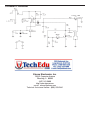
1
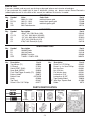
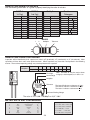
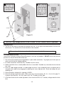
STROBE LIGHT KIT
MODEL AK-520
Assembly and Instruction Manual
Elenco Electronics, Inc.
Copyright © 1994 Elenco Electronics, Inc.
Revised 2002
REV-K
753018
PARTS LIST
If you are a student, and any parts are missing or damaged, please see instructor or bookstore.
If you purchased this strobe light kit from a distributor, catalog, etc., please contact Elenco Electronics
(address/phone/e-mail is at the back of this manual) for additional assistance, if needed.
RESISTORS
Qty.
1
2
1
1
Symbol
R1
R2, R4
R3
VR1
Value
200W 5% 1/4W
1MW 5% 1/4W
2MW 5% 1/4W
2MW Potentiometer
Color Code
red-black-brown-gold
brown-black-green-gold
red-black-green-gold
Part #
132000
171000
172000
192731
CAPACITORS
Qty.
1
2
1
1
1
Symbol
C5
C1, C3
C6
C4
C2
Description
.033mF 10% 250V Mylar (333)
.1mF 10% 100V Mylar (2A104K)
.1mF 10% 400V Mylar (2G104K)
.47mF 10% 250V Mylar (474)
470mF 10V Electrolytic (Lytic)
Part #
243319
251017
25102A
254717
284743
SEMICONDUCTORS
Qty.
1
1
1
1
Symbol
D2
D1
Q1
SCR
Description
1N4004 Diode
1N4148 Diode
2N3904 Transistor
T106D1 / C106D1 SCR
Part #
314004
314148
323904
3606D1
Qty.
1
1
1
1
1
1
1
1
1
1
Description
Part #
Transformer (T1)
440008
PC Board
517024
Switch DPDT (SW1)
541107
Neon Bulb (NEON)
585020
Flash Tube/Trigger Assembly (T2) 586005
Battery Holder
590072
Bottom Case
62PX2GB
Knob
622009
Top Panel
623107
Screw 2-56 x 5/8” Phillips
641277
MISCELLANEOUS
Qty.
4
2
1
1
1
1
1
1
15”
1
Description
Screw 4 x 1/2” Phillips
Screw 2 x .4 x 5mm Phillips
Nut Hex 7mm
Nut 2-56 Hex
Flat Washer 8mm
Lockwasher 5/16”
Lockwasher #2 INT
Tape Double-Sided
Wire 22ga. Topcoat Red
Solder
PARTS IDENTIFICATION
Resistor
Capacitors
Transistor
Transformer
Flash Tube/
Trigger
Diode
Mylar
Electrolytic
Potentiometer
SCR
Switch
or
-1-
Neon
PC Board
Part #
642465
643148
644101
644201
645101
646101
646200
740020
814200
9ST4
IDENTIFYING RESISTOR VALUES
Use the following information as a guide in properly identifying the value of resistors.
BAND 1
1st Digit
Color
Black
Brown
Red
Orange
Yellow
Green
Blue
Violet
Gray
White
Multiplier
BAND 2
2nd Digit
Digit
0
1
2
3
4
5
6
7
8
9
Color
Black
Brown
Red
Orange
Yellow
Green
Blue
Violet
Gray
White
Resistance
Tolerance
Color
Multiplier
Black
1
Brown
10
Red
100
Orange
1,000
Yellow
10,000
Green
100,000
Blue
1,000,000
Silver
0.01
Gold
0.1
Digit
0
1
2
3
4
5
6
7
8
9
Color
Silver
Gold
Brown
Red
Orange
Green
Blue
Violet
Tolerance
+10%
+5%
+1%
+2%
+3%
+0.5%
+0.25%
+0.1%
BANDS
1
2
Multiplier
Tolerance
IDENTIFYING CAPACITOR VALUES
Capacitors will be identified by their capacitance value in pF (picofarads), nF (nanofarads), or mF (microfarads). Most
capacitors will have their actual value printed on them. Some capacitors may have their value printed in the following
manner. The maximum operating voltage may also be printed on the capacitor.
Multiplier
For the No.
0
1
2
3
Multiply By
1
10
100
1k
4
5
8
10k 100k 0.01
9
0.1
Note: The letter “R” may be used at times
to signify a decimal point; as in 3R3 = 3.3
10mF 16V
First Digit
Second Digit
Multiplier
103K
Tolerance
100V
The letter M indicates a tolerance of +20%
The letter K indicates a tolerance of +10%
The letter J indicates a tolerance of +5%
Maximum Working Voltage
The value is 10 x 1,000 = 10,000pF or .01mF 100V
METRIC UNITS AND CONVERSIONS
Abbreviation
p
n
m
m
–
k
M
Means
Pico
nano
micro
milli
unit
kilo
mega
Multiply Unit By
.000000000001
.000000001
.000001
.001
1
1,000
1,000,000
Or
10-12
10-9
10-6
10-3
100
103
106
1. 1,000 pico units = 1 nano unit
2. 1,000 nano units = 1 micro unit
3. 1,000 micro units= 1 milli unit
4. 1,000 milli units = 1 unit
5. 1,000 units
= 1 kilo unit
6. 1,000 kilo units = 1 mega unit
-2-
INTRODUCTION
Have you ever seen a lightning flash and wonder
how the light was produced? This strobe light kit not
only explains how a high voltage discharge
produces light, but reproduces those bolts of
lightning in a small glass tube. Even more amazing
is the fact you will be able to control the moment
each flash occurs with a trigger circuit. Strobe lights
are used to stop motion by adjusting the trigger rate
to the speed of a moving object. They are also used
to produce light for photography at the moment the
camera shutter is opened. In the text that follows,
mechanical analogies are used to help explain
certain processes that are otherwise difficult to
visualize.
THEORY OF OPERATION
WHAT IS A GAS?
The amount of energy it takes to create an ion is
measured in electron volts. Table 1 shows the
energy needed to produce ions for different gases.
As you can see, Xenon requires much less energy
than Neon to produce ions. If the glass tube in your
kit contained Neon, the amount of energy needed to
ionize the gas would be 1.87 times greater. This
would shorten the life of the batteries by using
almost twice the energy for each flash. It is a law of
nature that opposite charges attract each other and
similar charges repel. When a gas molecule is
turned into a positive ion, it is attracted to a negative
charge. The a positive gas ion is placed in a strong
electric field, it will rapidly accelerate toward the
negative plate. As it moves, it will strike other gas
molecules, knocking electrons free and creating
more positive ions. These newly created ions will be
attracted by the negative plate, accelerate and
create even more positive ions (see Figure 3). The
avalanche process will continue until all of the gas in
the tube is ionized allowing a large current to flow
through the tube and collapse the electric field. As
the electrons are knocked about during the
ionization process,
Gas
Ionization
they release small
Energy
packets of energy
called photons that Helium
24.5
radiate from the Neon
21.5
tube. The human Nitrogen
16.7
eye perceives this
Hydrogen
15.9
burst of photons as
Argon
15.7
a brilliant flash of
Carbon Monoxide
14.2
light.
Oxygen
13.5
Krypton
13.3
Water Vapor
13.2
Xenon
11.5
Mercury
10.4
All matter is composed of atoms arranged in
patterns called molecules. In a solid, these
molecules are held in place and cannot move about
easily. In a liquid, the molecules move freely, but are
still loosely bound to each other. In a gas, the
molecules are separated by great distances and
bounce about like ping-pong balls in a large box.
The molecules of a gas are not bound to each other
and will dissipate into the surrounding space if
released from their container. These different states
of matter are shown in Figure 1.
Figure 1
Solid
Liquid
Gas
The glass tube in your strobe light kit is filled with a
rare gas called Xenon. This gas is used because it
is easy to ionize.
WHAT IS AN ION?
Gas atoms have no electronic charge on them in
their normal state. There are just as many positively
charged protons as there are negatively charged
electrons. Therefore, the net charge on the atom is
zero. If, however, a negatively charged electron is
removed from one of the atoms, the atom is left with
a positive charge and it is called a positive ion. This
creation of ions is shown in Figure 2.
Figure 2
Protons
Electrons
Normal Gas
Positive Ion
Molecule
Table 1
Negative Ion
-3-
pendulum in a grandfather clock. Once the
pendulum is started in motion, it will use only a
small amount of energy from the main spring to
keep it swinging at the exact same frequency. It is
this stable frequency rate that sets the time
accurately. If the weight is moved up the stick, the
frequency increases. This is called tuning the
frequency of the pendulum. In electronics, an
oscillator circuit also has tunable elements. The
inductor in a tuned electrical circuit is equivalent to
the length of the pendulum (see Figure 6).
Figure 3
Radiated Energy
Gas Molecule
Positive Ion
Negative Charge on Plate
GENERATING AN ELECTRIC FIELD
In order to ionize the Xenon gas in the glass tube,
the 3 volts DC at the battery must be transformed
into hundreds of volts DC. One of the electronic
devices used to “step up” voltages is called a
transformer. Transformers, however, only work with
AC voltages. You can think of a transformer as a
lever similar to the one shown in Figure 4. A small
movement on the short end of the lever will produce
a large swing on the other end. Since the lever does
not create energy, the power on one end must equal
the power on the other end. Therefore, the force
times the distance on the short end must equal the
force times the distance on the other end (as shown
in Figure 4).
Figure 6
MAKING THE FIRST ION
2 Inches
Weight = 2 lbs.
When the electric field is placed across the Xenon
tube nothing happens because there are no ions in
the tube to start the avalache process. A second
transformer is used to generate a very high voltage
spike on a piece of wire placed along side the tube.
This transformer is called the trigger transformer
since it “triggers” the avalanche process by forcing a
few ions to be produced momentarily in the tube.
This process is shown in Figure 7.
20 Inches
2 In. x 20 lbs. = 20 in. x 2 lbs.
Short Side
Long Side
Just like the lever, the transformer must have a
moving voltage (AC) to work. If the movement on
the short end of the lever equals zero, the
movement on the long end will also be zero.
Likewise, if DC is applied to one side of a
transformer, the output on the other side will be
zero. Since the transformer cannot create energy,
the power on one side must equal the power on the
other side. Electrical power is measured by
multiplying the voltage times the current (V x I).
Figure 5 shows the method used to transform the 3
volts from the battery to 200 volts needed for a
strong electric field.
=
Figure 7
Positive Ion
Wire with High
Voltage Spike
Electron Freed by
High Voltage Spike
300V x .003A
DC to AC
Converter
300 Volts DC
(Oscillator)
3V Battery
L = Inductance
By changing the position of the iron core in the
inductor, the inductance can be changed to tune the
oscillator to a desired radio frequency, just like
changing the weight of the pendulum would change
its frequency.
Figure 4
3V x .3A
C = Capacitance
L
Electronic
Tuned Circuit
in Oscillator
Weight
Force of 20 lbs.
Figure 5
C
Length
Transformer
Diode & Capacitor Converts AC to DC
An oscillator is an electronic circuit similar to the
-4-
Tube Filled
with Xenon
THEORY OF OPERATION
produce the avalanche process, as shown in Block 2.
After the high voltage is generated, a trigger pulse is
used to start the avalanche process (Block 3). Once
the gas in the flash tube (Block 4) is ionized, the
resistance of the tube drops and a large current flows
through the tube causing the high voltage to collapse.
The gas in the tube returns to its normal state (not
ionized) and the process starts over.
A block diagram is used to break down a system
into sub-systems that are easier to explain. All
strobe lights will have the blocks shown in Figure 8.
The power supply, Block 1, can be either an AC
(Alternating Current) or DC (Direct Current) source of
electrical power. When a low voltage DC source is
used, a battery for instance, the voltage must be
“stepped up” to the proper high voltage required to
Figure 8
1
POWER
SUPPLY
2
GENERATE
HIGH DC
VOLTAGE
3
TRIGGER
CIRCUIT
4
FLASH
TUBE
BLOCK 3 - The trigger circuit uses a neon light to
fire an SCR (Silicon Controlled Rectifier). The SCR
acts like a switch discharging capacitor C4 through
the primary of transformer T2. A high voltage spike
is produced on the secondary of T2. By using a
piece of wire, this trigger voltage is placed close to
the glass tube containing the xenon gas.
BLOCK 1 - Since the power supply in this kit is a
battery, it is a DC source. The low DC voltage must
be converted to a high DC voltage required by the
flash tube.
BLOCK 2 - Figure 5 shows a fundamental high
voltage generator. In this kit, a transistor is used for
an oscillator (Q1 on schematic drawing shown on
page 10). Q1 drives the primary of transformer T1
and the secondary also steps up the voltage
needed to flash the xenon tube.
BLOCK 4 - The flash tube consists of a hollow glass
tube filled with Xenon gas and sealed at each end
with a metal cap. Wires are connected to each of
the metal caps. When a high voltage is placed on
one cap and the other cap is grounded, a strong
electric field will appear across the tube.
-5-
CONSTRUCTION
Introduction
The most important factor in assembling your AK-520 Strobe Light Kit is good soldering techniques. Using the
proper soldering iron is of prime importance. A small pencil type soldering iron of 25 - 40 watts is
recommended. The tip of the iron must be kept clean at all times and well tinned.
Safety Procedures
• Wear eye protection when soldering.
• Locate soldering iron in an area where you do not have to go around it or reach over it.
• Do not hold solder in your mouth. Solder contains lead and is a toxic substance. Wash your hands
thoroughly after handling solder.
• Be sure that there is adequate ventilation present.
Assemble Components
In all of the following assembly steps, the components must be installed on the top side of the PC board unless
otherwise indicated. The top legend shows where each component goes. The leads pass through the
corresponding holes in the board and are soldered on the foil side.
Use only rosin core solder of 63/37 alloy.
DO NOT USE ACID CORE SOLDER!
What Good Soldering Looks Like
Types of Poor Soldering Connections
A good solder connection should be bright, shiny,
smooth, and uniformly flowed over all surfaces.
1.
Solder all components from
the copper foil side only.
Push the soldering iron tip
against both the lead and
the circuit board foil.
1. Insufficient heat - the
solder will not flow onto the
lead as shown.
Soldering Iron
Component Lead
Foil
Soldering iron positioned
incorrectly.
Circuit Board
2.
3.
4.
Apply a small amount of
solder to the iron tip. This
allows the heat to leave the
iron and onto the foil.
Immediately apply solder to
the opposite side of the
connection, away from the
iron.
Allow the heated
component and the circuit
foil to melt the solder.
Allow the solder to flow
around the connection.
Then, remove the solder
and the iron and let the
connection cool.
The
solder should have flowed
smoothly and not lump
around the wire lead.
Rosin
2. Insufficient solder - let the
solder flow over the
connection until it is
covered. Use just enough
solder
to
cover
the
connection.
Soldering Iron
Solder
Foil
Solder
Gap
Component Lead
Solder
3. Excessive solder - could
make connections that you
did not intend to between
adjacent foil areas or
terminals.
Soldering Iron
Solder
Foil
4. Solder bridges - occur
when solder runs between
circuit paths and creates a
short circuit. This is usually
caused by using too much
solder.
To correct this,
simply drag your soldering
iron across the solder
bridge as shown.
Here is what a good solder
connection looks like.
-6-
Soldering Iron
Foil
Drag
ASSEMBLE COMPONENTS TO THE PC BOARD
C5 - .033mF (333) Mylar Cap.
C6 - .1mF (2G104K) Mylar Cap.
Wire 1” - Cut a 1” wire and strip
both ends. Solder one end to
the PC board marked (+).
SCR - T106D1 SCR (Fig. D)
C4 - .47mF (474) Mylar Cap.
R3 - 2MW 5% 1/4W Resistor
(red-black-green-gold)
D2 - 1N4004 Diode (Fig. B)
Wire 1” - Cut a 1” wire and strip
both ends. Solder one end to
the PC board marked (–).
R4 - 1MW 5% 1/4W Resistor
(brown-black-green-gold)
C3 - .1mF (2A104K) Mylar Cap.
R2 - 1MW 5% 1/4W Resistor
(brown-black-green-gold)
R1 - 200W 5% 1/4W Resistor
(red-black-brown-gold)
NEON - Neon Lamp
T1 - Transformer
D1 - 1N4148 Glass Diode (Fig. B)
VR1 - 2MW Potentiometer
Cut three 3” red wires and
solder them to the PC board
marked 1-2-3. Then solder the
other ends to the 2MW pot as
shown.
C2 - 470mF Lytic Capacitor (Fig. C)
Cut the tab off of the 2MW pot.
Q1 - Transistor 2N3904 (Fig. A)
C1 - .1mF (2A104K) Mylar Cap.
BATT - Battery Wires
Solder the black battery holder
wire to the BATT (–) Hole
marked on the PC board.
Black (–)
Solder the red battery holder
wire to the left lug of the switch.
Red (+)
Solder the 2” red wire to the
BATT (+) hole on the PC board.
Then, solder the other end to
the middle lug of the switch.
Switch
Cut off tab
Figure B
Figure A
Figure C
Diodes have polarity. Mount them
with the band in the correct direction,
as shown on the top legend.
Mount the transistor onto
the PC board with the
flat side in the same
direction as shown on
the top legend.
Glass
Electrolytics have a polarity
marking indicating the (–) lead.
The PC board is marked to
show the lead position.
With Beveled Edge
Metal
Backing
UNITS IN INCHES
2
(+)
Figure D
PC Board
Marking
1
(–)
Mount the SCR in the same direction as marked on
the PC board.
Epoxy
¼ ½
Polarity
Marking
PC Board
Marking
Band
0
VR1 - 2MW Potentiometer
3
4
Use this ruler to measure the wires when cutting them to their required lengths.
-7-
FINAL ASSEMBLY
Wire from (–)
Legend Side
of PC Board
Wire from (+)
Insert
Figure 9
1
Foil Side of
PC Board
T2 (See Figure 9) Insert the flash tube
assembly and solder T2 to
the PC board as shown in
Figures 10-12.
Push in until
it snaps.
Figure 10
Figure 11
Back Cover
Figure 12
Figure 13
2-56 Nut
2
Solder the wires from
the (+) and (–) points
on the PC board to
the flash tube (see
Figure 12).
Lockwasher
3
Assemble the PC
board, switch and pot
to the front panel as
shown.
4
Remove the backing on both sides
of the double-sided tape and apply
it to the back of the battery holder.
Now, place the battery holder
inside of the case as shown in
Figure 14.
Insert three “AA” size (alkaline
only) batteries into the battery
holder.
Double-sided
Tape
Battery Holder
Front Cover
8mm Flat Washer
5/16” Lockwasher
2-56 x 5/8” Screw
Top
7mm Hex Nut
Figure 14
2 x 0.4 x 5mm Screws
Note: Be sure that you place the battery holder at the bottom of the back cover as shown
in Figure 14. Also, make sure that the three positive (+) battery terminals are pushed up
against the battery holder contacts.
-8-
Place the lid onto
the case and
secure it with four
4 x 1/2” screws
(see Figure 15).
Knob - Turn the
shaft on the pot
counter-clockwise
all of the way.
Install the knob
with
the
line
pointing in the
direction as shown
in Figure 16.
Strobe Light Kit
AK-520
OFF
ON
FLASH RATE
4 x 1/2” Screws
Figure 16
Figure 15
CAUTION: High voltage present on the PC board. DO NOT handle it while in operation!
OPERATION
1. Turn the unit on and turn the knob to the desired flash rate. As you adjust the knob clockwise, the flash rate
will increase. The maximum flash rate should be at the mid point.
The maximum flash rate can be adjusted to approximately 4 times per second.
TROUBLESHOOTING
Consult your instructor or contact Elenco Electronics if you have any problems. DO NOT contact your place of
purchase as they will not be able to help you.
1. One of the most frequently occurring problems is poor solder connections. Tug slightly on all of the parts to
make sure that they are indeed soldered.
2. All solder connections should be shiny. Resolder any that are not.
3. Solder should flow into a smooth puddle rather than a round ball. Resolder any connection that has formed
into a ball.
4. Have any solder bridges formed? A solder bridge may occur if you accidentally touch an adjacent foil by
using too much solder or by dragging the soldering iron across adjacent foils. Break the bridge with your
soldering iron.
5. Check the battery voltage with a voltmeter (4.5VDC).
6. Check the voltage across C4 for 250 - 350V. If less, then check the battery, R1, C1 - C3, Q1, D2 and/or T1.
If greater, then check R2 - R4, VR1, Neon, SCR, C6, T2 and/or the flash tube.
7. If the Neon flashes but the strobe light doesn’t, then check the SCR, C6, T2, battery voltage and/or the flash
tube.
-9-
GLOSSARY
AC Voltage
A voltage that varies, usually above and below zero volts, thus causing the current to alternate.
Atom
The smallest part into which matter can be divided and still maintain its identity.
Avalanche
An increase in moving particles due to sudden impact.
Electric Field
The force that exists when a difference in charge occurs.
Electron
A tiny negatively charged particle that rotates around the nucleus of an atom.
Electron-volts A unit of energy equal to 1.602 x 10⁻¹⁹ joules.
Energy
Effective force. The capacity for doing work.
Force
The cause that changes bodies from a state of rest to motion or from motion to rest.
Gas
An air-like substance without definite shape or volume, tending to expand indefinitely when
unconfined. One of the three forms in which matter can exist.
Ion
An electrically charged particle that enables the flow of electricity.
Liquid
One of the three forms in which matter can exist separately and still maintain the character of
that substance.
Neon
A gaseous element, inert, colorless, and found in the atomosphere.
Photons
A unit of light measurement.
Power
The mechanical rate at which energy is exerted or work done.
Proton
The smallest unit of positive charge in an atom.
Solid
One of three forms in which matter can exist, having a definite volume and a definite shape.
Transformer
A device used for converting an alternating electric current from one voltage to another.
Xenon
A gaseous element which belongs to the group of inert gases. It occurs in air in minute traces.
QUIZ
1. All matter is composed of atoms arranged in patterns called _______________.
2. In their normal state, the net charge on a molecule of gas is _______________.
3. When a molecule of gas is positively charged it is called a _______________.
4. Xenon requires less _______________ than Neon to produce ions.
5. A positive ion will accelerate toward a _______________ charged plate.
6. During the ionization and avalanche process, small packets of energy called _______________ radiate from
the glass tube.
7. The _______________ is used to step-up an AC voltage.
8. Electrical power is measured by multiplying _______________ times _______________.
9. The _______________ transformer is used to produce the first ions.
10. A negative ion has on more _______________ than it has protons.
Answers: 1. Molecules; 2. Zero; 3. Positive Ion; 4. Energy; 5. Negative; 6. Photons; 7. Transformer;
8. Voltage, Current; 9. Trigger; 10. Electron.
-10-
SCHEMATIC DIAGRAM
Elenco Electronics, Inc.
150 W. Carpenter Avenue
Wheeling, IL 60090
(847) 541-3800
http://www.elenco.com
e-mail: [email protected]
Technical Assistance Hotline: (800) 533-2441