1
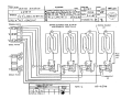
WELLS MANUFACTURING COMPANY
PRELIMINARY SERVICE MANUAL
GENERAL
The model G 246W is a 208 volt Griddle. Factory mired For three phase operation (see
wiring diagram # 41394 for single phase connections).
The Griddle has two control panels housing two control thermostats and two indicator
lamps For each half of the Griddle.
The Griddle has an (total of four) individual thermostat For each of the four heating
surfaces.
The Griddle has a four-section (eight elements arranged in Four groups of two elements)
heating surface.
Each element section and its control thermostat have a pilot lamp assembly (indicator) to
show when the element is heating.
The cooking surface of the Griddle can be set for variable temperatures across the
cooking surface (ie. hotter in the center or at one side or the other).
Service information and procedures contained in the following pages are a guide for
maintenance of the Griddle. Service and repair of this equipment should be performed only
by qualified and trained service personnel.
It is our belief that the information enclosed in this manual is accurate in detail as of
the date of publication and is subject to revision as further information becomes
available.
-
1
-
PN#62444
SERVICE PROCEDURES
NOTE: The pilot lamps an this unit cycle on and off with the thermostats when the power is
on. the pilot lamps can be used in the Following manner to aid in troubleshooting the unit
(see troubleshooting guide).
To service the Griddle, access to the back side of the control panels of griddle is
required, and to the underside of griddle may be required.
WITH POWER TURNED "OFF". Open the control panels, proceed with tests below to make
your continuity tests.
ELEMENT TESTS
When testing the elements for continuity and/or resistance at the thermostat terminals you
mill be reading TWO elements in PARALLEL and the cold resistance will be one half that of
an individual element, or 7.3 to 8.85 Ohms.
If you read 15.9 to 17.7 Ohms at the thermostat terminals and all the element jumpers (#5)
are installed, then one element is OPEN (bad). Replace the element.
If you read no continuity, check for a broken wire or open (bad) elements. Replace wire if
broken. IF not, replace the defective element.
THERMOSTAT TESTS
The thermostat Pt.# 61396 has an operating range of 100 to 450 degree F. with two pole
30A. contacts rated at 277U resistive load.
With power "OFF" to the griddle, test thermostat (#1) For continuity, advance the
thermostat to a temperature setting higher than the griddle surface.
The contacts should now be CLOSED. IF not, the thermostat should be replaced.
Disassembly of element and thermostat assemblies.
Use care in disassembling the control panels and thermostat assemblies, as the
capillary tubes are Fragile.
After determining the parts that must be replaced, remove the bottom cover (# 31) screws
and the bottom cover plate (#l). See Drawing # 21054.
-
2
-
It will be necessary to remove the insulation pad over the element and thermostat clamps
in order to remove the element and sensing bulb clamps.
It mill also require removing the Jumper straps (#5) that are over the insulation pad in
that area.
To remove the insulation pad, bend the insulation tie-down tabs (#18 see Drawing # 21054)
into a vertical position and expose the element and thermostat clamps by carefully Folding
the insulation pad away From the area that requires service.
Remove the element and/or thermostat clamps that are holding the components that require
service. Use care in disassembly to avoid damage to thermostat capillary tube, bulb
assemblies, electrical wiring and components (Note routing of each capillary tube for
reassembly, see drawing # 41397 & 21054).
REPLACEMENT OF ELECTRICAL and MECHANICAL COMPONENTS
When replacement oF elements is required, make sure the new elements are mounted
Firmly to bottom of the griddle by the element clamps (# 4).
When replacing element or thermostat miring use only factory approved type mire, see parts
list For correct specification and type.
When installing new components use EXTREME CAUTION to insure that the capillary tube/bulb
units are NOT kinked or flattened. Route excess tube length into gentle bends to avoid
kinks and sharp bends.
In replacing heating elements, control thermostats, associated wiring and electrical
components be sure to support all terminals with pliers when tightening attachment
terminals to avoid damage to components.
Use standard service practice of full contact between platen (Griddle Plate) and heating
elements. Use anti-sieze on all studs For mounting element and sensing bulb clamps.
Element clamps and electrical connections must be tight and Free From contact with
surrounding wires and connections.
Reassembly (see drawing #41337)
After replacing thermostats, re-mount thermostat body to control panels after sensing tube
assemblies have been installed in the holding clamps (#2, see drawing # 41397) located
next to the element mounting clamps (#4 see cautions on capillary tubes above).
-
3
-
Be sure that the sensing bulb assemblies are inserted into the mounting clamp (#19 see Drawing
# 21054) and under the element clamp that the thermostat is to control (not crossed over to
the next element assembly).
Rewire per wiring diagram # 41394 and re-tighten all electrical connections (support each
component connection while tightening;
too much mechanical pressure from hand tools may damage components).
INSPECTION AFTER REPLACEMENT OF COMPONENTS
Inspect the complete Griddle For proper routing of electrical mires, electrical,
mechanical components.
CAUTION:Recheck thermostat wire terminals For tightness prior to Final mounting of control
panel.
During Final mounting of control panel, make sure thermostat capillary tubing is stowed well
clear of all "hot" terminals on thermostat housing and elements.
TESTING GRIDDLE OPERATION
Connect Griddle to 208 Volt power source and turn on each thermostat and check L1-L2-L3
current draw with an ampmeter. See miring diagram Car name plate) for correct line current
drain . After all elements have been tested and Found to be within normal readings, the
Calibration Procedure should be performed (see calibration procedures).
EQUIPMENT REQUIRED TO CALIBRATE THERMOSTATS
A-
Digital thermometer (Pyrometer).
B-
Remote heads (thermocouples) for the above tester.
CD-
Thermostat knob(s) (see helpful hint) with hole through center. USE SPARE KNOB ONLY!
Small flat blade screw driver.
- 4 -
GRIDDLE SURFACE PREPARATION
Locate and mark Four spots as follows on the Griddle surface to measure the surface
temperature.
Locate the center line both horizontal and vertical on the griddle surface. Pencil the
lines on the griddle Surface.(a line side to side and top to bottom)
#1- 12 inches in from the front edge of the cooking surface and 6 inches in from the right
edge.
#2- 12 inches in from the front edge of the cooking surface and 6 inches in from the left
edge.
#3- 12 inches in from the front edge of the cooking surface and 6 inches to the left of
the center line.
#4- 12 inches in from the front edge of the cooking surface and 6 inches to the right of
the center line.
HELPFUL HINT
To calibrate each thermostat it requires access to
hollow control shaft of the thermostat. A modified
the center of a spare knob (use only a spare knob,
driver access to adjusting screw) without removing
the calibration screw located inside the
control knob(s) (drill a hole through
not one from the griddle!) gain screw
knob(s) from thermostat.
CALIBRATION PROCEDURE
With power (208V. 1 or 3 ph.) connected to Griddle, do the following: Set all four
thermostats to 200 degrees F., allow the Griddle to cycle through one complete heating
cycle of each of the four elements and thermostats. There mill be some overshoot on the
first heating cycle.
Place the thermocouple sensing head on spot # 1 as marked in preparation section above. You
will need to test all four spots in this procedure.
Place modified control knob(s) on thermostat shaft(s) and set to 200 degrees F.
Insert small flat blade screw driver in thermostat shaft and align into the calibration
screw inside thermostat shaft. CAUTION NOTE:
When adjusting the calibration screw on the thermostat. DO NOT TURN MORE THAN ONE FULL
TURN! SEVERE DAMAGE TO THE THERHOSTAT MAY RESULT.
-
5
-
Turning the calibration screm clockmise decreases the temperature, and counter-clockwise
increases the temperature. 1/8 of a turn will cause approximately 10 Degrees F. of change
in temperature. WARNING, SEE CAUTION NOTE ABOVE!
When thermometer (Pyrometer) indicates 2OO degrees F., adjust the calibration screw
(clockwise) to cause the thermostat(s) to open (The pilot lamp mill go OFF as the
thermostat contacts open) . Repeat For each of the Four marks on the Griddle.
Advance the control knob(s) to read E50 degrees F. and match pilot lamp. The correct
reading on the thermometer (Pyrometer) is 243 to 253 degrees F.(when the thermostat opens
the pilot lamp mill go OFF). Note the reading and if it is mithin the limits listed then
no further calibration for that location mill be required.
If the reading is out of the range For the 250 degrees F. setting, then adjust the
knob(s) to 300 degrees F. and match the reading on the thermometer (Pyrometer). As
pilot lamp goes OFF the reading should be 293 degrees F. to 303 degrees F.. If out
range adjust the calibration screw inside the thermostat shaft(s) to bring the cut
into the correct range.
control
the
of this
off
Set the control knob(s) back down to 220 degrees F. and allow the Griddle to cool to the
point that the thermostat(s) closes (turns back ON) . Watch to see if it turns OFF within
193 to 223 degrees F. IF it is NOT mithin these limits then repeat the calibration
procedures For that thermostat
When all Four sections have readings that are mithin the limits stated above calibration
is completed.
Model G-245W Griddle Suggested repair parts inventory
items
PART #
Rec. Qty.
DESCRIPTION
50513
4
Element, 2500 W. 208 V.
50516
2
Light, signal amber
52054
2
Jumper, element
56051
1
Insulation pad kit
57707
100 ft.
Wire, 12Ga. Hi. Temp.
5BB52
100 ft.
Wire, 18Ga. Hi. Temp. Sil. Rub.
61396
2
Thermostat, control
61490
2
Knob, thermostat
-6-
WELLS Manufacturing Co.
Drawing No. 21054 Page 1 of 2 Parts List
For Model # G246W (08/18/86)
PART
NUMBER
DESCRIPTION
# PER
UNIT
1
61389
Cover, bottom
1
2
41443
Anchor, electrical box
1
3
41454
Skeleton, Frame assembly
2
4
50513
Element, 20BV. 2500V.
8
5
61394
Diagram, wiring
1
6
41391
Shroud, Front and rear
2
7
41392
Shroud, side
2
8
41386
Control Panel, left
1
9
41385
Control Panel, right
1
10
61396
Thermostat
4
11
61490
Knob, thermostat
4
12
50516
Light, signal amber
4
13
41450
Box, electrical outlet
1
14
52063
Cover, electrical outlet
1
15
61387
Clamp, element
8
16
61388
Clamp, thermostat bulb
8
17
52054
Jumper, element
8
18
53474
Clip, insulation tie-down
20
19
61390
Holder, tube thermo. capillary
4
20
61393
Plate, indicator thermostat
4
21
41438
Nameplate, specification
1
22
55849
Trademark, logo
1
23
51038
Retainer, escutcheon
3
25
51276
Terminal Block
1
ITEM #
P-10
- Pkg. 10 P- 50 - Pkg. 50 A/R - As Required
P-25
= Pkg. 25 P-100 = Pkg. 100 L/P = Local Purchase
-
8
-
F/0- Factory
Order
NOTES
P-10
P-10
WELLS Manufacturing Co.
Parts List for model # G246W
Drawing No. 21054
Page 2 of 2
(08/18/86)
PART
NUMBER
DESCRIPTION
26
51040
Grommet, insulation 7/8 in.
2
27
51061
Tie, cable small
6
***
61623
Chute assembly, grease disposal
2
29
41399
Frame top assembly
1
30
53935
Screw, truss hd. # 5
1
31
37725
Screw, st. # 8
8
32
31730
Screw, truss hd. 8-32
8
33
31082
Nut, hex kep 8-32 UNC
10
34
31704
Nut, hex 8-32 UNC Ni.
32
35
31253
Nut, hex 1/4-20 UNC
104
ITEM #
***
# PER
UNIT
= SHOWN ON SEPARATE SHEET
39
40
41
42
43
44
45
46
47
48
49
P-10 Pkg. 10
P-50 - Pkg.
50 A/R - As Required F/O - Factory
p-25 Pkg. 25 P-100 - Pkg. 100 L/P - Local Purchase
-
9
-
Order
NOTES