1
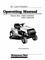
42"
Lawn
Tractors
Operating
Model
Manual
Nos.
TMO-3100002
TMO-3395309
Model TM0-3395309
Shown
Mom_me_ Wazd
INDEX
Dear Customer,
So often throughout the year we are all in a
rush to meet our daily obhgations.
However, we at Montgomery Ward are taking
a quick moment out to say...
"Thank you for your business."
Sincerely,
MONTGOMERY WARD
Rules for Safe Operation ............................................
3
Assembly Instructions .................................................
4
Controls ......................................................................
7
Operation ....................................................................
9
Adjustments ..............................................................
10
Lubrication ................................................................
13
Maintenance .............................................................
13
Off-Season Storage ..................................................
17
Trouble Shooting Guide ......................................
18, 19
Electrical System ......................................................
19
Illustrated Parts for Lawn Tractors ....................... 20-30
Slope Gauge .............................................................
31
Parts Information ........................................
Back Cover
BOL ARE FOR PERSONAL SAFETY. BE
SURE
NSTRUCTIONS
TO FOLLOW
GIVEN
THEM.
WITH THIS SYM- I
_
NOTICE: A data plate with the model number and serial numbers of your unit is located on the frame,
under the seat. Record these numbers in the spaces provided on the back cover of this guide.
BEFORE YOU CALL SERVICE
Check Spark Plug Wire
• Firmly attached?
• Wire terminal clean?
Check Crankcase Oil Level
• Overfilled/underfilled?
Check Fuel Tank
• Fuel in tank?
• Fuel dirty or stale?
• If tank has been empty
fill tank completely.
for a long period,
Check Air Cleaner
• Clean?
• Choke plate stuck?
• Governor spring free to move?
Check under Blade Housing (Disconnect
• Blade obstructed or bent?
Check Starting Instructions
• Read instruction
manuals
instructions.
and labels
Spark Plug First)
for specific
WARNING: This unit is equipped with an internal combustion engine and should not be used on or near any unimproved forest-covered, brush-covered or grass-covered land unless the engine's exhaust system is equipped with a
spark arrester meeting applicable local or state laws (if any). If a spark arrester is used, it should be maintained in
effective working order by the operator.
In the State of California the above is required by law (Section 4442 of the California Public Resources Code).
Other states may have similar laws. Federal laws apply on federal lands, A spark arrester for the muffler is available through your nearest engine authorized service center or contact the parts sales center of Montgomery Ward.
2
IMP0 RTANT
,_k
AL SAFETY AND/OR PROPERTY OF YOURSELF AND OTHERS. READ AND FOLLOW ALL INSTRUCTIONS IN THIS MANUAL
THIS SYMBOL POINTS OUT IMPORTANT SAFETY INSTRUCTIONSWHICH, IF NOT FOLLOWED,COULD ENDANGERTHE PERSONBEFOREATTEMPTINGTO OPERATEYOUR UNIT. WHEN YOU SEETHIS SYMBOL-- ,_
HEEDITS WARNING.
41dkDANGER:
,L_
sA,=,=
oP,=.,,-.o.
the
salety instructionscould
result in serious
or death.
Thisfollowing
cutting machine
is capable of amputating
hands injury
and feet
and throwing objects. Failure to observe
I.
6ENERAL OPERATION
1. Read, .understand, and follow all instructions in the manual and
on the machine before starting. Keep this manual in a safe
place for future reference and for ordering replacement parts.
2. Only allow responsible adults familiar with the instructions to
operate the machine. Know controls and how to stop the
machine quickly,
3. Do not put hands or feet under cutting deck or near rotating
parts.
4. Clear the area of objects such as rocks, toys, wire, etc. which
could be picked up and thrown by the blade. A small object
may have been overlooked and could be accidentally thrown by
the mower in any direction and cause injury to you or a
bystander. Always wear safety glasses or eye shields during
operation or while performing an adjustment or repair, to protect eyes from foreign objects. Stop the blade(s) when crossing gravel drives, walks or roads_
5. Be sure the area is clear of other people before mowing. Stop
machine if anyone enters the area.
6 Never carry passengers.
7. Disengage blade(s) before shifting into reverse and backing up.
Always look bown and behind before and while backing.
8. Be aware of the mower and attachment discharge direction and
do not point it at anyone, Do not operate the mower without
either the-entire grass catcher or the chute guard in place,
9 Slow down before turning. Operate the tractor smoothly. Avoid
erratic operation and excessive speed.
10 Never leave a running machine unattended. Always turn off
blade(s), place transmission in neutral, set park brake, stop
engine and remove key before dismounting.
11 Turn oft blade(s) when hal mowing.
12. Stop engine and wait until blade(s) comes to a complete stop
before (a) removing grass catcher or unclogging chute, or (b)
making any repairs, adjusting or removing any grass or debris.
13. Mow only in daylight or good artificial light.
14. Do not operate the machine while under the influence of alcohol or drugs.
15, Watch for traffic when operating near or crossing roadways.
16. Use extra care when loading or unloading the machine into a
trailer or truck. This unit should not be driven up or down a
ramp onto a trailer or truck under power, because the unit
Could tip over, causing serious personal injury, The unit must
be pushed manually to load or unload properly
17. Never make a cutting height adjustment while engine is running if operator must dismount to do so,
18. Wear sturdy, rough-soled work shoes and close-fitting slacks
and shirts. Do not wear loose fitting clothes or jewelry. They
can be caught in moving pads. Never operate a unit in bare
feet, sandals, or sneakers.
19. Check overhead clearance carefully before driving under power
lines, wires, bridges or low hanging tree branches, before
entering or leaving buildings, or in any other situation where
the operator may be struck or pulled from the unit, which
could result in serious injury.
20. Disengage all attachment clutches, thoroughly depress the
brake pedal, and shift into neutral before attempting to start
engine.
II.
SLOPEOPERATION
Slopes are a major factor related to loss of control and tip-over
accidents which can result in severe injury or death. All slopes
require extra cautLon If you cannot back up the slope or if you feel
uneasy on it, do not mow it.
DO:
Mow up and down slopes, not across
Remove obstacles such as rocks, limbs, etc.
Watch for holes, ruts or bumps. Uneven terrain could overturn the
machine. Tall grass can hide obstacles,
Use slow speed. Choose a low enough gear so that you will not
have to stop or shift while on the slope. Always keep ,tractor in gear
when going down slopes to take advantage of engine braking
action..
Follow the manufacturer's recommendations for wheel weights or
counterweights to improve stability.
Use extra care with grass catchersor other attachments. These can
change the stability of the machine.
Keep all movement on the slopes slow and gradual. Do not make
sudden changes in speed or direction. Rapid engagement or braking could cause the front of the machine to lift and rapidly flip over
backwards which could cause serious injury.
Avoid starting or stopping on a slope. If tires lose traction, disengage the blade(s) and proceed slowly straight down the slope.
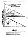
For your safety, use the slope gauge included as part o! this manual
to measure slopes before operating this unit on a sloped or hilly
area. If the slope is greater than 15° as shown on the slope gauge,
do not operate this unit on that area or serious injury could result.
DO NOT:
Do not turn on slopes unless necessary; then, turn slowly and
gradually downhill, if possible.
13onot mow near drop-offs, ditches or embankments. A wheel over
the edge or an edge caving in could cause sudden overturn,
Do not mow on wet grass. Reduced traction could cause sliding.
Do not try to stabilize the machine by putting your foot on the
ground.
Do not use grass catcher on steep slopes.
ill. CHILOREM
Tragic accidents can occur if the operator is not alert to the presence of children. Children are often attracted to the machine and
the mowing activity. Never assume that children will remain where
you last saw them
1. Keep children out of the mowing area and in watchful care of
an adult other than the operator.
2. Be alert and turn machineoff if children enter the area.
3. Before and when hacking, look behind and down for small children.
4. Never carry children. They may fall off and be seriously injured
or interfere with the safe machine operation.
5, Never allow children under 14 years old to operate the
machine. Children 14 years and over should only operate
machine under close parental supervision and proper instruction.
6, Use extra care when approaching blind corners, shrubs, trees
or other objects that may obscure vision.
IV. _r,BYJ
£_
1.Useextracarein handling
gasoline
andotherfuels.They are
flammable and vapors are explosive.
a. Use only an approved container.
b. Never remove gas cap or add fuel with the engine running
Allow engine to cool at least two minutes before refueling.
Do not smoke.
c. Never refuel the machine indoors.
d. Never store the machine or fuel container inside where
there is an open flame, or spark, s_ch as a water heater.
space heater, clothes dryer and the like.
Never run a machine inside a closed area.
Check frequently and keep nuts and bolts, especially blade
attachment bolts, tight and keep equipment in safe working
condition.
Never tamper wilh safety devices. Check their proper operation
regularly. Use all guards as instructed in this manual.
To reduce fire hazard, keep machine free of grass, leaves or
2.
3.
4.
5
I ,_
6.
7.
8.
g.
10.
11.
12.
other debris build-up. Clean up oil or fuel spillage. Allow
machine to cool before storing.
Stop and inspect the equipment for damage if you strike an
object. Repair, if necessary, before re-starting and operating
the machine
Never make adjustments or repairs with the engine running.
Grass catcher components are subjecl to wear. damage and
deteriorate, which could expose moving parts or ailow objects
to be thrown. Frequently, check components and replace with
manufacturer's recommended parts when necessary.
Mower blades are sharp and can cut. Wrap the blade(s) or
wear gloves and use extra caution when serwcmg blade(s).
Check brake operation frequently. Adjust and service as
required.
Muffler engine, and belt guards become hot during operation
and can cause a burn. Allow to cool down before touching
Do not change the engine governor settings or overspeed the
engine.
DANGER: of power equipment,
carelessnessor error on the part of the operator can resull in serious injury. If you viuYour
unitofwas
built
Io be
operated
according
the rules
for safe
late any
these
ru!es,
you
may cause
serioustoinjury
to yoursell
oroperation
others. in this manual. As with any type
ASSEMBLY
INSTRUCTIONS
IMPORTANT: After assembly, service engine with
gasoline, and check oil level as instructed in the
separate engine manual packed with your unit.
NOTE: Reference to right or left hand side of the
unit is observed from the driver's seat, facing forward.
Self-Tapping
Screws
UNPACKING
1. Remove
the lawn tractor from the carton as follows. Open the top flaps. The loose parts (include
the battery fluid, steering wheel with steering cap
attached and chute deflector) are on the seat and
wrapped
in plastic. Remove all carton inserts. Cut
the front corners
of the carton.
Make certain
brake is released,
and push the unit out of the
carton.
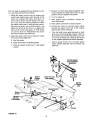
2. The seat has been mounted backward for shipping purposes. Carefully cut and remove the plastic wrap. Remove the loose parts from the seat.
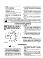
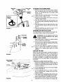
-_--ASSEMBLING THE SEAT
\
Remove the hex self-tapping
screws which secure the
seat to the seat pivot bracket. Turn the seat around
and place in position
against the seat pivot bracket,
lining up the slotted holes in the pivot bracket with the
holes in the seat. Select desired position for the seat,
and secure with hex self-tapping
screws. See figure 1.
FIGURE 1.
&
'BATTERYINFORMATION
WARNING
A. Battery acid must be handled with great care as
contact with it can burn and blister the skin. It is
also advisable to wear protective clothing (goggles,
rubber gloves and apron) when working with it.*
B. Should battery acid accidentally splatter into the
eyes or onto the face, rinse the affected area
immediately with clean cold water. If there is any
further discomfort, seek prompt medical attention.
C.
If acid spills on clothing,
first dilute
water, then neutralize
with a solution
water or baking soda/water.
Since battery acid is corrosive, do not pour it into
any sink or drain. Before discarding empty electrolyte containers, rinse them with a neutralizing
solution.
E,
NEVER connect or disconnect charger clips to
battery while charger is turned on as it can cause
sparks.
F. Keep all lighted materials (cigarettes,
matches,
lighters) away from the battery as the hydrogen
gas generated during charging can be combustible.
G. As a further precaution, only charge the battery in
a well-ventilated area.
*Always shield eyes, protect skin and clothing
when working near batteries.
D.
it with clean
of ammonia/
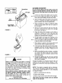
ACTIVATING THE BATTERY
,;_Battery
Cover
Battery
/
Screwdriver
Do not activate battery (fill with battery acid) until
battery is actually placed in service. Be certain to
read previous warnings before activating the battery.
Caps
Vent
Elbow
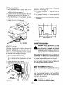
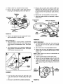
1. Lift the seat. Remove the battery cover by pressing in on the sides and lifting up. See figure 2
inset. Remove the battery from the rear frame.
2. Open the battery pack. Be careful not to puncture
the box. It contains the battery fluid (acid) in a
plastic container and one short plastic tube.
3. Place the battery on a table or workbench. Make
certain the long plastic drain tube is in place on
the vent elbow.
Clear Plastic
Drain Tube
4. Remove the six fill caps from the top of the battery with a screwdriver. Be careful not to damage
the fill caps. See figure 2.
FIGURE 2.
5. Place the battery fluid container on the table or
workbench. Carefully cut off tip of the spout and
attach the short plastic tube provided. Do not
squeeze the container when cutting tip.
6. Fill each battery cell slowly and carefully to the
UPPER LEVEL line marked on battery. See figure 3. Use caution as the acid level will rise rapidly alter the bottom of the cell is filled.
7. Allow battery to stand for 30 minutes with the fill
caps removed, while the plates absorb acid.
8. If acid level has fallen after the 30 minute standing period, refill each cell with battery acid to the
UPPER LEVEL line on battery. Replace the fill
caps.
9. Before discarding the empty container, neutralize
any residue with baking soda and rinse container
with water. Puncture container several times
before discarding.
FIGURE 3.
DANGER
Battery contains sulfuric acid. Refer to-warning
on page 4. Antidote: EXTERNAL--Flush
with
water. INTERNAL--Drink
large quantities of water
or milk. Follow with milk of magnesia, beaten eggs
or vegetable oil. Call physician immediately. EYES:
Flush with cool water for at least 15 minutes, then
get prompt medical attention.
Since batteries produce explosive gases, keep
all lighted materials (cigarettes, lighters, matches, etc.) away. Be sure to charge battery only in
well-ventilated areas. Make certain venting path of
battery (drain tube) is always open.
KEEP BATTERIES
OUT OF THE REACH OF CHILDREN!
10. Charge the battery after the 30 minute standing
period. SLOW CHARGE THE BATTERY (DO
NOT FAST CHARGE).
Charge the battery at a maximum bench rate of 2
amperes until the specific gravity reading is 1.265.
Charge for a minimum of 3 hours and a maximum of 5
hours.
NOTE:
This engine
is equipped
with an alternator.
The current for the battery charger alternator is unregulated. During normal operation, it is only necessary
to charge the battery:
1. When
it is activated
for the first time.
2. Before winter storage.
3. Before
using the lawn tractor after winter storage.
After battery has been charged,
water. Do not add acid.
add
only
distilled
Steerin
Cap
Lock
Nut
AllACHING THE STEERING WHEEL
1. Remove the hex lock nut and cupped washer
from the steering shaft, and remove the steering
bellow. Pry the steering cap off the center of the
steering wheel.
Washer
2. Attach one end of steering bellow to the steering
-<------ wheel as shown in figure 4, inset.
3. Position the front wheels of the tractor so they are
pointing straight forward.
Steering
Bellow
4. Place the steering wheel and steering bellow over
the steering shaft, positioning steering wheel as
desired.
5. Place the washer with the cupped side down over
the steering shaft. Secure with hex lock nut. See
figure 4.
6. Place the steering cap over the center
steering wheel and seat it with your hand.
FIGURE 4.
of the
ATTACHING THE CHUTE DEFLECTOR
The chute deflector must be attached to the right side
of the deck so that it covers the chute opening.
_..._-
Hex Nuts
WARNING:
unless
the
properly
\_
Washers
='-'7;'
//
u
installed.
position
Remove the truss machine screws, cupped washers and hex nuts which are attached
to the deck
next to the chute opening.
.'Machine
.--_--_--S".E..2/
JI._', ',Screws
""
your
unit
has been
Make certain deck is raised to its highest
(lift lever pulled all the way back).
2.
;//_..._ _
Do not operate
chute
deflector
3.
',I
I
ii',
l'i
Place the chute deflector
in position as shown in
figure 5. Secure
with hardware
just removed.
Cupped side ol washers
goes against the chute
deflector.
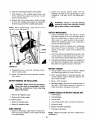
LEVELING THE DECK
With unit on hard, level surface, measure the distance
from the bottom edge of the center of the left side of
deck to the ground. Measure the same distance just
behind the chute area on the right side of the deck.
Or, place the blades in a straight line, and measure
the distance from the outside edge of the blade tips to
the ground.
FIGURE 5.
Deck Hanger
___
If adjustment is needed, proceed as follows.
1. Remove the hairpin clip and flat washer from the
bottom of the adjustable lift link on the left side of
the deck. (Hairpin clip and flat washer are on the
inside of the lift link.)
,
Pull the adjustable lift link out of the deck hanger
channel. See figure 6.
3. Turn the adjustable lift link up or down as necessary to level the deck. Usually only one or two
turns are needed.
4. Insert the end of the adjustable lift link into the hole
in the deck hanger channel. Recheck the adjustment as instructed above. Readjust if necessary.
5. When deck is level, secure the end of the
adjustabre lift link with flat washer and hairpin clip.
FIGURE 6.
6
.Negative
Terminal
Battery
Drain
TubeI
Positive
:rminal
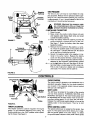
TIRE PRESSURE
The tires on your unit may be over-inflated for shipping purposes. Reduce the tire pressure before operating the unit. Recommended operating tire pressure
is approximately 12 p.s,i. (check sidewall o! tire for tire
manufacturer's recommended pressure).
any circumstances
is 30 p.s.i. Equal tire
WARNING: Maximum tire pressure under
pressure should be maintained on all tires,
_-INSTALLING
Red
(Positive)
Cable
Black
(Negative)
Cable
FIGURE 7.
Cable
Transaxle
"
Drain
Tube
Tie_
Re' _lfra%Ckeel_le
nt _
THE BATTERY
1. Raise the seat.
2. Make certain the positive cable (heavy red wire)
and negative cable (heavy black wire) are routed
outside the battery opening.
3. Place the battery inside the opening so that the
positive terminal is toward the front of the unit.
See figure 7. Route the battery drain tube down
beside the battery.
4. Remove the hex bolt from the positive (+) terminal, Place the positive cable on the positive terminal. See figure 7. Secure with hex bolt, Be careful
not to lose the nut inside the terminal.
5. Secure the negative cable to the negative (-) terminal in the same manner. Replace the battery
cover over the positive terminal. Lower the seat.
6. Insert the drain tube through the cable tie which is
attached to the transaxle reinforcement bracket
on the right side of the unit. See figure 8. Be certain drain tube is routed away from the wheel rim.
Pull on end of cable tie to tighten (do not collapse
drain tube). Trim excess end of cable tie.
FIGURE 8.
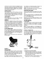
CONTROLS
Clutch-Brake
Pedal
CHOKECONTROL
The choke control is located on the dashboard and is
operated manually. Details for the choke operation
are covered in the separate engine manual packed
with your unit. See figure 9.
Ignition
Control
Throttle
Ammeter
Light Switch
Shift
Lever
Choke
FIGURE 9.
SHIFT LEVER
The shift lever is located in the center of the console
and has three positions, FORWARD, NEUTRAL and
REVERSE. See figure 9. The clutch-brake pedal must
be depressed and the lawn tractor must not be moving when shifting gears. Do not force the shift lever.
Release the clutch-brake pedal slightly to line up the
shifting collar in the transmission.
Then try to shift
gears.
THROTI'LE CONTROL
SPEED CONTROL LEVER
The throttle control is used to regulate the engine
speed. To get maximum efficiency from cutting, the
throttle should be in the FAST position when operating the mower. See figure 9.
The speed control lever is located 'on the fender. See
figure 10. The speed control lever allows you to regulate the ground speed of the lawn tractor. To select
the ground speed, depress clutch pedal. Move speed
controlleverout of the notchesandbackwardto slow
lawntractor,forwardto increasespeed.Whendesired
speedhas beenobtained,releaseleverin thatposition.Wheneverclutchis engaged, unit will automatically go to the pre-set speed.
Release
pedal.
the
NOTE: The parking brake must be set ff the operator
leaves the seat with the engine running.
INTERLOCKS (Not Shown)
IGNITION SWITCH
Turn the key to the START position to start the
engine. When the engine is running, let the key return
to the ON position. To stop the engine, turn the key to
the left to the OFF position and remove it to prevent
accidental starting. See figure 9.
LIGHT SWITCH
Push the light switch to turn on the lights. The lights
will only operate when the engine is running.
AMMETER
The ammeter registers the rate of battery charge or
discharge. The ammeter will register on the discharging side when starting lhe engine. It should register on
the opposite side (charging) when the engine is running in the fast position until the battery is completely
charged. With a fully charged battery or with the
engine idling, the ammeter will not show a charge.
See figure 9.
CLUTCH-BRAKE PEDAL
The clutch-brake pedal is located on the left side of
the lawn tractor. Depressing the clutch-brake pedal
part way disengages the clutch. Pressing the pedal all
the way down disengages the clutch and engages the
disc brake. See figure 9.
NOTE: The clutch-brake
start the engine.
the notches to the desired position.
speed control lever and the clutch-brake
peda! must be depressed
to
Interlock safety switches are located by the clutchbrake pedal, the lift lever, the shift lever and under the
seat.
Before the engine will start, the clutch-brake pedal
must be depressed all the way and the lift lever must
be in the disengaged position.
Before the unit can be shifted into reverse or if the
operator leaves the seat, the lift lever must be in the
disengaged position.
CUTTING CONTROLS
A. LIFT LEVER
The lift lever is used to raise and lower the cutting
deck and to engage and disengage
the blades.
Pulling it all the way back and locking it disengages
the blades.
NOTE: The lift lever must be in the disengaged position when starting the engine, when shifting into
reverse and if the operator leaves the seal See figure
11.
B. DECK LIFT INDICATOR
The deck lift indicator marks the position being used
for the lift lever. Select the lift lever position desired,
press the indicator lever outward, move it to the position immediately below the lift lever and release the
indicator lever. See figure 11.
_peed
Control
FIGURE 10.
¢k Lift
Indicator
FIGURE
11.
PARKING BRAKE
The speed control lever is used to set the parking
brake. To set the parking brake, depress the clutchbrake pedal. Move the speed control lever out of the
notches to desired position. Release the speed control lever and the clutch-brake pedal.
To release the parking brake, depress the clutchbrake pedal and move the speed control lever out of
C. SETTING
THE
CUTTING
HEIGHT
1. Select the position
for the lift lever which gives
the desired cutting height. Move the deck lift indicator so that the lift lever can be returned
to the
same position after it is raised.
2. Move the deck wheels to the hole location so the
wheels are 1/4 to 1/2 inch above the ground.
OPERATION
3.. Set the throttle control in the FAST position. See
figure 9.
WARNING
4. Pull out choke knob to choke engine
engine may not require choking).
AVOID SERIOUS INJURY OR DEATH
GO UP AND DOWN SLOPES, NOT ACROSS.• AVOID SUDDENTURNS.
DO NOT OPERATE]-HE UNIT WHERE IT COULD SLIP OR TIP.
IF MACHINE STOPS GOING UPHILL, STOP BLADE(S) AND BACK
DOWNHILL SLOWLY.
DO NOT MOW WHEN CHILDREN OR OTHERS AREAROUND.
NEVER CARRY CHILDREN.
LOOK DOWN AND BEHIND BEFOREAND WHILE BACKING.
KEEP SAFETY DEVICES (GUARDS, SHIELDS, AND SWITCHES) IN
PLACE AND WORKING.
REMOVEOBJECTSTHAT COULD BETHROWN BY THE BLADE(S).
KNOW LOCATIONAND FUNCTION OFALL CONTROLS.
BE SURE BLADE(S) AND ENGINE ARE STOPPED BEFORE PLACING
HANDS OR FEETNEARBLADE(S).
BEFORE LEAVING OPERATOR'S POSITION, DISENGAGE BLADE(S),
PLACE THE SHIF'[ LEVER IN NEUTRAL, ENGAGE BRAKE LOCK, SHUT
ENGINE OFFAND REMOVEKEY
(a warm
5. Turn the ignition key to the START position.
When the engine is running, let the key return to
the ON position. See figure 9.
6. Push choke knob in gradually. Move the throttle
control to desired engine speed.
STOPPING THE ENGINE
Turn the ignition key to the left to the OFF position.
Remove the key to prevent accidental starting.
IMPORTANT; If you strike a foreign object, stop the
engine. Remove wire from spark plug, thoroughly
inspect the unit for any damage, and repair the damage before restarting and operating the mower.
READ OPERATOR'S MANUAL
NOTE: If any problems are encountered,
Trouble Shooting Guide on page !8.
GAS AND OIL FILL-UP
Check oil level and add if necessary. Service the
engine with gasoline as instructed in the separate
engine manual packed with your tractor. Read
instructions carefully.
refer to the
OPERATING THE LAWN TRACTOR
1. Set the desired cutting height.
IMPORTANT: Your tractor is shipped with oil; however, you must check the oil level before operating. Be
careful not to overfill.
2. Start the engine as instructed previously.
3. Move throttle control to 3/4 or full throttle to prevent strain on the engine and to operate the cutting blades.
4. Place the shift lever in either the FORWARD
REVERSE position.
with
engine Never
runningfill or
WARNING:
fuelwhile
tank engine
indoors,is
hot.
or
STARTING THE ENGINE
1. Depress the clutch-brake
ing brake.
pedal and set the pa_'k-
2. Place the lift lever in the DISENGAGED
See figure 11.
WARNING:
ing up.
position.
5. Release the
clutch-brake
speed control
tion. Use first
Look to the rear before back-
parking brake by depressing
the
pedal, pressing
outward on the
lever and moving to desired posispeed position when operating the
IMPORTANT:
This unit is equipped with a safety
interlock system
for your protection.
The purpose of
the safe_y in½er!ock system ;_ to preven_t th_ _ngino
from cranking or starting unless the clutch-brake
pedal is depressed and the lift lever is in the disengaged position. In addition, the lift lever must be in the
disengaged position when the unit is put into reverse
or the engine will shut off. If the operator leaves the
seat with the lift lever engaged and/or without setting
the parking brake, the engine will shut off.
NOTE: When operating the unit initially, there will be
little difference between the highest two speeds until
after the belts have seated themselves into the pulleys during the break-in period.
tor if the interlock system is malfunctionWARNING: Do not operate the lawn tracIng because
it is a safety
device,
designed for protection.
Be sure that the lawn is clear of stones, sticks, wire,
or other objects which could damage lawn mower or
engine. For best results and to insure more even
grass distribution, do not mow when lawn is excessively wet.
lawn
tractor
lor
the
first time.
6. Releaseclutch-DraKepeclal810wlyto putunitinto
motion.
7. The lawn tractor is brought to a stop by depressing the clutch-brake pedal.
9
WARNING:Beforeleavingthe operator's
position for any reason, disengage the
blades, place the shift lever in neutral,
engage the parking brake, shut engine
off andremovethe key.
ADJUSTMENTS
SEAT ADJUSTMENT
The seat may be adjusted
to seat installation
section
to different
of assembly
positions.
Refer
instructions.
When stopping the unit to empty a grass bag, etc., follow the instructions
above. This procedure
will also
eliminate
"browning"
the grass, which is caused
by
hot exhaust gases from a running engine.
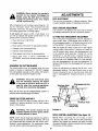
DECK LEVELING ADJUSTMENT
If unit stalls with speed control in high speed, or if
unit will not operate with speed control lever in a low
speed position, proceed as follows.
CUTTING DECK ENGAGEMENT ADJUSTMENT
If an uneven cut is obtained,
the deck may be leveled
by following instructions
at end of assembly
section.
The cutting
deck engagement
may be adjusted
to
make certain deck is disengaged
when lift lever is in
the disengaged
position, or to obtain more drive in the
cutting positions.
Correct adjustment
as follows.
1. Place shift lever in NEUTRAL.
2.
Restart
engine.
3.
Place speed
4.
Release
clutch-brake
pedal fully.
5.
Depress
clutch-brake
pedal.
6.
Place speed
7.
Place
shift
REVERSE,
dures.
control
control
lever
lever in high speed
lever in desired
in
and follow
either
normal
position.
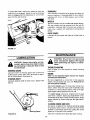
With the engine off, place the lift lever in the highest
cutting position
(first position).
Remove the cotter pin
and flat washer which secure the disengagement
rod
to the stabilizer
shaft assembly.
Shorten the rod by
threading
it in until the ferrule is against the back of
the slot in the lift shaft assembly,
and the rod lines up
with the hole in the stabilizer shaft. For more belt ten-
position.
FORWARD
operating
or
proce-
OPERATING THE CUTi'ING BLADES
sion the disengagement
rod must be lengthened.
To
decrease
belt tension the disengagement
rod must be
shortened.
The cutting
blades may be engaged
while the lawn
tractor
is moving
or standing
still. DO NOT engage
the cutting blades abruptly as the sudden belt tension
on the pulley may cause the engine to stall.
Check the adjustment
by placing the lift lever in the
disengaged
position.
The deck should move up and
forward,
allowing
the belt to become loose. Start and
test for disengagement.
Repeat procedure
as necessary.
WARNING:
Keep feet and hands
away
from the discharge
opening,
the blades
or any part of the deck. When the unit is
used for other than mowing
operations,
the blade drive should be disengaged.
Move the lift lever into the DISENGAGED
raise the deck and disengage the blades.
Stabilizer Shaft
Assembly
Disengagement
Rod
position to
Sprin!
GRASS COLLECTORAVAILABLE
GRASS
COLLECTOR
available
as optional
shown in this manual.
stock number
89-35111R
is
equipment
for the lawn tractors
Stabilizer
Plate
Flat Washer
Hairpin Clip
FIGURE 12.
,_
NOTE:
operated
entireshould
grass catcher
WARNING:without
The the
mower
not be
or chute deflector in place.
Under
normal
usage
bag material
is subject
SPEED CONTROL ADJUSTMENT (See figure 13)
to
NOTE:
When
operating
the unit initially
or after
replacing
the belts,
there will be little difference
between
the highest
two speeds
until after the belts
have gone through a break-in period and have seated
themselves
into the pulleys,
wear, and should be checked
periodically.
Be sure
any replacement
bag complies
with the mower manufacturer's
recommendations.
For replacement
bags,
use only factory authorized
replacement
bag.
10
D. Release the clutch-brake pedal completely, then
slowly depress the pedal all the way (to park
position). Hold the pedal in this position.
If the full range of speeds cannot be obtained on your
unit, adjust the speed control as follows.
1. Adjust the speed control lever by pushing the
clutch-brake pedal forward until the stop on the
brake rod is against the frame. See figure t3.
Have another person hold the pedal in this position as you make the following adjustment. Place
the speed control lever in parking brake position.
Remove the hairpin clip and flat washer, and
adjust the ferrule on the rod so it is against the
back end of the slot. See figure 13. Then lengthen rod one more turn. Reassemble and secure
with theflat washer and hairpin clip.
E. Turn the engine off.
F. After engine stops
clutch-brake pedal.
release
the
G. Place speed control lever in second position.
H_ Remove the cotter pin and flat washer which
secures the speed control link to the variable
speed torque bracket assembly.
I.
Push the clutch-brake pedal backward by hand
as far as it will go using light pressure. Hold it in
this position as you thread the speed control link
in or out of the ferrule until it lines up with the pin
on the variable speed torque bracket assembly.
J.
Secure speed
torque bracket
cotter pin.
2. Adjust the speed control link as follows to obtain
the correct neutral adjustment.
A. Start the engine.
B. Place the shift lever in Neutral position.
C. Place the speed control lever in high speed
position.
"_-._
Speed
Control
completely,
control link to variable speed
assembly with flat washer and
Variable Speed
Torque Bracket
Assembly
Cotter Pin and
Flat Washer
Speed
Link
Brake
Rod
Ferrule
FIGURE 13.
11
NEUTRAL ADJUSTMENT
1. Place the transmission
in neutral.
move freely when pushed forward
with the parking brake released.)
2.
Loosen
the
assembly
3.
bolt
which
secures
the shift
to the shift lever link. See figure
Place the shift lever in the neutral
14.
4. Tighten
Dimension "B" should be approximately
Dimension "A." See figure 16.
(The unit will
and backward
A.) To increase Dimension
rod end.
lever
1/8" less than
"B," screw tie rod into tie
B.) To decrease Dimension "B," unscrew tie rod from
tie rod end.
14.
slot. See figure
C.) Reassemble tie rod. Check dimensions.
if necessary.
Readjust
the bolt to 13 foot pounds.
tral
Slot
Lever
Front
l_
FIGURE
Loosen
Bolt
FIGURE
1
16.
CARBURETOR ADJUSTMENT
14.
WHEEL ADJUSTMENT
to the engine while the engine is running
WARNING: If any adjustments are made
(e.g. carburetor), disengage all clutches
and blades. Keep clear of all moving
parts. Be careful of heated surfaces and
muffler.
The caster
(forward
slant of the king pin) and the
camber
(tilt of the wheels out at the top) require no
adjustment.
Automotive
steering principles
have been
used to determine
the caster and camber on the tractor. The front wheels should toe-in 1/8 inch.
To adjust
the toe-in,
proceed
Minor carburetor adjustment may be required to
compensate for differences in fuel, temperature,
altitude and load. To adjust the carburetor, refer to
the separate engine manual packed with your unit.
as follows.
1. Remove
the hex nut and lock washer, and drop
the tie rod end from the wheel bracket. See figure
15.
2.
°
(118" Less Than A)
Loosen
3. Adjust
NOTE: A dirty air cleaner wilt cause an engine to run
rough. Be certain air cleaner is clean and attached to
the carburetor before adjusting carburetor.
the hex jam nut on tie rod.
the tie rod assembly
for correct
toe-in.
BRAKE ADJUSTMENT (See figure 17)
NOTE:
instead
17.
Rod
The brake is located by the right rear wheel inside the
frame. During normal operation
of this machine,
the
brake is subject
to wear and will require
periodic
examination
and adjustment.
Hex
Nut
Hex Nut
Lock Washer
Your brake may be equipped
with a lock nut
of the castle nut and cotter pin shown in figure
Tie Rod
End
/
/
ning when you
the the
brake.
WARNING:
Do adjust
not have
engine run-
FIGURE 15.
12
To adjustthe brake,removethe cotterpinfromthe
castlenut(if so equipped).Adjustthe nutsothe brake
startsto engagewhenthe brakeleveris 1/4"to 5/16"
awayfromthe axlehousing.
TRANSAXLE
The transaxle is lubricated at the factory and does not
require checking.
If disassembled
for any reason,
lubricate with 10 oz. of Shell grease, part number
737-0148.
WHEELS
The front wheels may be provided with grease fittings.
The rear wheels must be removed from the axle for
lubrication. Lubricate both front and rear wheels at
least once a season with automotive multi-purpose
grease.
PIVOT POINTS
Lubricate all pivot points with light oit at least once a
season.
Castle
Nut
FIGURE 17.
MAINTENANCE
LUBRICATION
,_
WARNING:
Disconnect
the spark plug
wires and ground against the engine
before performing any repairs or maintenance.
connect spark plug wires before cleanWARNING: Always stop engine and dising, lubricating or doing any kind of work
on lawn tractor.
TROUBLE SHOOTING
Refer to page 18 of this manual for trouble shooting
informalion.
STEERING GEARS
Lubricate teeth of steering gears with automotive
multi-purpose grease after every 25 hours of operation or once a season. See figure 18.
ENGINE
Refer to the separate engine
maintenance instructions.
STEERING SHAFT
Lubricate
light oil.
manual
for engine
Maintain engine oil as instructed in the separate
engine manual packed with your unit. Read and follow instructions carefully.
steering shaft at least once a season with
Service air cleaner every 10 hours under normal conditions. Clean every few hours under extremely dusty
conditions. To service the air cleaner, refer to the separate engine manual packed with your unit.
The spark plugs should be cleaned and the gap
reset once a season. Spark plug replacement is recommended at the start of each mowing season; check
engine manual for correct plug type and gap specifications.
CLEANING ENGINE AND DECK
Any fuel or oil spilled on the machine should be wiped
off promptly. Grass, leaves, and other dirt must not be
allowed to accumulate around the cooling fins of the
engine or on any part of the machine.
Steering Gears
FIGURE
18.
Clean the underside of the deck after each mowing.
13
CUTTING BLADES
A. Removal
for Sharpening
DRIVE BELTREMOVAL AND REPLACEMENT
or Replacement
wire
and ground
it against
engine.
WARNING:
Disconnect
the the
spark
plug
Block the wheels of the unit,
ground the spark plug wire and remove
WARNING:
Be sure to disconnect
and
ignition key before working on the cutting
blade to prevent accidental engine starting. Protect hands by using heavy gloves
or a rag to grasp the cutting blades.
NOTE:
Figures
19, 22 and 23 are shown
tipped up for clarity.
to remove the belts.
However,
1. Remove the large bolt and lock washer which
holds the blade and adapter to the blade spindle.
ff tipping
It is not necessary
the unit is desired,
with the unit
to tip the unit
remove
the bat-
tery from the unit. To prevent gasoline
leakage, drain
the gasoline, or remove the fuel tank cap, place a thin
piece of plastic
over the neck of the fuel tank and
2. Remove the blade and adapter from the spindle.
screw
on the cap. Be certain to remove
the plastic
when finished changing
the belts. Block unit securely.
3. If the blade or blade adapter needs replacing,
remove the two small bolts, lock washers and
nuts which hold the blade to the adapter.
DECK
B. Sharpening
Remove the cutting blades by following the directions
of the preceding section.
BELT
1. Place the lift lever
2.
When sharpening the blades, follow the original angle
of grind as a guide. It is extremely important
that
each cutting edge receives an equal amount of grinding to prevent an unbalanced blade. An unbalanced
blade will cause excessive vibration when rotating at
high speeds, may cause damage to the mower and
could break, causing personal injury.
position.
Remove the hex bolts (belt keepers) and cupped
washers
from the engine pulley belt guard. See
figure 19.
NOTE:
cupped
When reassembling,
make certain
washers are assembled
in the same
from which
they were
Cupped
Washer
The blade can be tested for balance by balancing it
on a round shaft screwdriver. Remove metal from the
heavy side until it balances evenly,
in the disengaged
removed.
See figure
Hex Bolts
hex and
locations
19.
Cupped
NOTE: It is recommended that the blade always be
removed from the adapter for the best test of balance.
C. Reassembly
Before reassembling the blade and the blade adapter
to the unit, lubricate the spindle and the inner surface
of the blade adapter with light oil. Lubricating the bolt
holes, bolts and inner surface of the nuts with light oil
is also recommended. A 4 oz. plastic bottle of light oil
lubricant is available. Order part number 737-0170.
Engine oil may also be used.
When replacing blades, be sure to install the blade
with the side of the blade marked "Bottom" (or with
part number) facing the ground when the mower is in
the operating position.
FIGURE
3.
Unhook
4.
Blade Mounting Torque
Center Bolt: 450 in. Ibs. rain., 600 in. Ibs.'max.
Blade Adapter Bolts: 200 in. Ibs. rain., 350 in. Ibs. max.
the deck belt from
.
Place the lift lever in the engaged
ward) position.
Disconnect
hairpin clips
the six deck links
and flat washers.
FUEL FILTER
7.
Your unit is equipped
with a replaceable
in-line fuel filter. Replace
filter whenever
contamination
or discoloration
is noticed.
Order replacement
filter through
your engine authorized
service dealer.
8. Place the lift lever
14
the engine
pulley.
(all the way for-
Disconnect
the spring
which
is attached
to a
bracket
on the transaxle,
inside
the left rear
wheel. Use a spring puller or other suitable tool.
5.
To insure safe operation of your unit, all nuts and bolts
must be checked periodically for correct tightness.
19.
by removing
the
Disconnect
the stabilizer
plate from the stabilizer
shaft assembly
by removing
the hairpin clips and
flat washers and sliding out the rod. Refer to figure 12.
in the disengaged
position.
5. Remove the two bolts which hold the shift lever
bracket to the frame on the left side of the unit.
Swing the bracket toward the right so the belt can
be removed from the transmission pulley. See figure 22.
9. Slide the deck from beneath the lawn tractor.
10. Remove the belt guards at each deck pulley by
removing the self-tapping screws. See figure 20.
Stabilizer
Plate
6. Replace belt, and reassemble
Belt
Guard
in reverse order.
7. Adjust the speed control as instructed
ment section.
Self-Tapping
Screws
Transmission
Pulley
in adjust-
Shift Lever Bracket
Hex Bolt
Rear
Drive
Belt
Belt Guard
Idler
Pulley
FIGURE 20.
11. Remove and replace the belt, reassemble
ing the instructions in reverse order.
Variable.
Speed Pulley
follow-
FIGURE 22.
REAR DRIVE BELT
1. Place shift lever in neutral position. Unscrew the
shift knob. Remove the two truss head screws
which secure the transmission cover. See figure
21A.
FRONT DRIVE BELT
1. To remove the front drive belt, first remove the
rear drive belt from the idler pulley and variable
speed pulley.
2. Lift the transmission cover. Unplug the safety wire
from beneath the transmission cover. See figure
21B. Remove transmission cover.
2, Place the lift lever in the disengaged position.
3. Remove the hex bolts (belt keepers) arid cupped
washers from the engine pulley belt guard. Refer
to figure 19.
NOTE: Make certain hex bolts are reassembled
shown in figure 19.
as
4. Unhook the deck belt from the engine pulley.
5, Remove the two self-tapping screws on each
of the frame which hold the engine pulley
guard to the frame. See figure 23. Remove
engine pulley belt guard by slipping it forward
down.
side
belt
the
and
Wire
Self ;,Tapping
Screws
SelfTapping (
Screws
FIGURE 21.
3. Push the idler pulley toward the right side of the
unit. Lift the belt over the idler pulley. See figure
22.
Engine Pulley
Belt Guard
FIGURE 23.
4. Remove the belt from the variable speed pulley.
15
6. Place the clutch-brake
pedal in park position.
2. Attach
the second
jumper
cable from the
Negative terminal of the good battery to the
FRAME OF THE UNIT WITH THE DEAD BATTERY.
7. Push forward on the variable speed pulley, and
lift the belt off the engine and remove the belt
from the engine pulley.
8. Release the clutch-brake pedal. Using the pedal
to move the variable speed pulley as necessary,
lift the belt up and off the variable speed pulley.
NOTE:
When
inside the pins.
reassembling,
See figure 24.
make
certain
belt
procedure
cause
and the
WARNING: could
Failure
to sparking,
use this starting
gas in either battery could explode.
is
BATTERY MAINTENANCE
Variable
Speed Pulle
1. Check
periodically
(every two weeks or before
and after charging)
to be sure electrolyte
level is
above the lowest line on battery.
Add only distilled
water or a good quality
drinking
water.
NEVER add additional
acid or other chemicals
to
battery
after initial activation.
2. The battery should be checked with a hydrometer
after every 25 hours of operation.
If the specific
gravity
is less than 1.225, remove
battery
and
recharge.
3. Coat the terminals
and exposed wiring with a thin
coat of grease or petroleum
jelly for longer service and protection
against electrolyte
corrosion.
4. The battery
acid should
Be careful
FIGURE
should be kept clean, Any deposits of
be neutralized
with soda and water.
not to get this solution
in the cells.
24.
BATTERY STORAGE
9. Reassemble with a new belt, following
tions in reverse order.
instruc-
1. Charge battery
store discharged
10. Adjust the speed control as instructed in adjustment section.
using normal
methods.
NEVER
battery as it will not recover.
2. When storing battery for extended
connect
battery
cables.
Removing
unit is recommended.
BATTERY REMOVAL OR INSTALLATION
WARNING:
When removing
the battery,
follow this order of disassembly
to prevent
the screwdriver
from
shorting
against the frame.
periods,
battery
disfrom
3.
Store in cold, dry place.
4.
Recharge
battery whenever
the specific gravity is
less than 1.225, before
returning
to service,
or
every two months, whichever
occurs first.
COMMON CAUSES FOR BATTERY FAILURE ARE:
1. Remove
the Negative
2.
the Positive
Remove
1. Overcharging
cable.
cable.
To install a battery:
1, Attach
the Positive
2.
the Negative
Attach
cable.
cable.
2.
Undercharging
3.
Lack of water
4.
Loose
5.
Excessive
holds downs
6. Battery
JUMP STARTING
7_ Freezing
1. Attach the first jumper cable from the Positive terminal of the good battery to the Positive terminal
of the dead battery.
corroded
connections
loads
electrolyte
substitutes
of electrolyte
NOTE:
THESE
WARRANTY.
16
and/or
FAILURES
DO
NOT
CONSTITUTE
TIRES
4. Refer to battery storage instructions on page 16.
Recommended
operating
tire pressure
is approximately 12 p.s.i. (check sidewall of tire for tire manufacturer's
recommended
pressure).
Maximum
tire
pressure
under any circumstances
is 30 p,s.i. Equal
tire pressure should be maintained
on all tires.
5. Store unit in a clean, dry area. Do not store next
to corrosive materials, such as fertilizer.
NOTE: When storing any type of power equipment in
an unventilated or metal storage shed, care should be
taken to rustproof the equipment. Using a light oil or
sificone, coat the equipment, especially any chains,
springs, bearings and cables.
When installing
a tire to the rim, be certain
rim is
clean and free of rust. Lubricate
both the tire and rim
generously.
beads.
Never
inflate
to over
30 p.s.i,
to seat
WARNING:
Excessive
pressure
(over 30
p.s.i.)
when
seating
beads
may cause
tire/rim assembly
to burst with force sufficient to cause serious injury.
OFF-SEASON
STORAGE
If the machine is to be inoperative
for a period
than 30 days, prepare for storage as follows.
1. Clean
the engine
2. Lubricate
machine
OPTIONAL
EQUIPMENT
longer
At the time of manufacture
al accessories
listed below
and the entire unit thoroughly.
all lubrication
points, Wipe the entire
with an oiled rag to protect the surfaces.
Description
36;' Snow Thrower
42" Snow Blade
Grass Collector
42" Mulching Kit
30 Lb. Wheel Weights
3. Refer to the engine
manual
for correct
engine
storage
instructions.
The engine must be completely drained
ef fuel to prevent
gum deposits
from forming
on essential
carburetor
parts, fuel
lines and fuel tanks.
17
of lawn tractor,
are available.
Stock
No.
80-3384806
80-3387908
80-3511103
80-3520109
80-3386204
the option-
TROUBLE
TROUBLE
Engine
crank
will not
LOOK
Battery
rectly
SHOOTING
GUIDE
FOR
installed
REMEDY
incor-
The battery
must be installed
with the negative
terminal,
identified
-), groundecL
The positive
terminal
(Pos. P or +) attaches
to the
small
Blown fuse or circuit
breaker
red wire
Replace
from
fuse
the fuse
with 7-1Y2 amp.
musl
be corrected
dead
short
and
exposed
Check
may
Battery is dead or weak
the
bare
Use
a moving
(1.215
determined.
wire.
to check
s.g.
fuse.
Fuses
or charging
circuit
where
or repair
with
the
between
wire
body
panels,
to the positive
seldom
in the fuse
the condition
minimum
wire.
needed
battery.
(3) Charging
The charging
system
3600 r.p,m. A diode
engine
type
is also attached
connections
Replace
pinched
(1)Defective
for grounded
automotive
for loose
breaker
fail without
holder.
Replace
the
insulation
electrician's
burned
by the
tape
The
holder
may
exhaust
terminal.
a reason.
fuse
N or
The
have
if the
pipe
problem
if necessary.
rubbed
wire
strands
or muffler
A
through
have
or rubbed
part
a hydromete_
80°F.
or circuit
be in the cranking
not been damaged.
Note: Look for a wire
against
holder
at the terminal post by (Neg,
large cable from the solenoid.
of the
battery.
for cranking
Battery
system
The
engine).
will not accept
Specific
The
Gravity
reason
or hold
(s.g.)
for the
should
battery
a full charge.
be 1 265
failing
(2) Short
must
circuit.
at
be
Check
not working.
is an alternator
located
under the flywheel.
{rectifier)
is located
in the output
lead just
It is unregulated
before
the wire
and rated 3 amp. at
harness
plug on the
side
Wire
._
To Alternator
Shrink
Tube
Diode
pL=__
•
-
(_ _- -
3 AMP DC
(Bart.)
/
/'7 AMP AC
:-J_'-_ Lf (Lamps)
-- -,
_=="
"--5
r
Black
Wire
The
diode
changes
A.C,
to D.C.
to charge
or discharge
the battery if the alternator
lead from the battery
(small
red wire)
charge
lead
and the positive
terminal
Polarized
Plug
the battery.
A bad diode
can either
fail to charge
of the battery.
(3) With
the engine
off, the lamp should
it does, the diode and possibly
the alternator
should be replaced.
(4) Start the engine
light. It it does not, the alternator
(stalor)
or lead wire is bad and shouid
be replaced.
Mechanical
failure
The
(Wires and switches)
interlock
circuit
mower
system
includes
two
mechanical
activated
switches
used to energize
the starter
solenoid.
While
testing the
temporarily
unsafe
by permitting
the engine to be started
WARNING:
While
testing,
disengage
the clutch,
shut
off the
place the gear shift lever in neutral.
Attach a wire (minimum
battery
and touch the other end to the small terminal on the
the engine
is bad.
cranks,
starler
the solenoid
motor
wilh one of the safety
and the small terminal
switch.
Engine cranks
,but will not start
Throttle
or choke
starting
position
not in
No spark to spark plug
Replace
Check owner's
tested
(3) If the engine
by an authorized
engine
does
dealer.
are
wired
not light.
lamp
in series
control,
set the parking
If
should
in the
make the
engaged.
brake
and
18 gauge)
to the positive terminal of the
solenoid.
If the engine
does not crank:
or poor ground.
(2) The solenoid
(#8 gauge minimum)
and jumping
the
which
The
interlock
system,
you will
with the blade and clutch
blade
(1) There
is a loose connection
checked
by using a heavy wire
have
the battery
is shorted
as well as the diode
To test: (1) Disconnect
charger
(2) Connect
12 V small test lamp between
the 3 amp. D.C.
may be
between
not crank
bad. The solenoid
can
the two large terminals,
when
If the engine
you
does
jump
crank,
the
be
tf
solenoid,
the problem
is
switches,
ignition switch or the wire between
the fuse holder
{or circuit breaker)
on the solenoid.
Note: Look for a poor connection
at the switches
or a defective
if necessary.
guide for correct position for throttle control and choke for starting.
Spark plug lead disconnected. Connect lead. Hold spark plug lead away from engine block about 1/8".
Crank engine There should be a spark If not, have engine repaired at authorized engine service
dealer.
Faulty spark plug. To test, remove spark plug. Attach spark plug lead to spark plug. Ground the spark
plug body against the engine block. Crank the engine. The spark plug should fire at the electrode.
Replace if it does not.
18
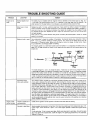
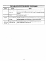
TROUBLE
TROUBLE
LOOK
SHOOTING
FOR
REMEDY
No fuel to the carburetor
Gasoline
Fuel
Air filter
Engine
smokes
Engine
dirty
loses crankcase
Dipstick
Bent
vibration
spindle
damage.
Bent
Stop
will
not
Engine
or damaged
blade
speed
Transmission
grass
uncut
Blades
or leaves
strips
blade
short
Stop
engine
low
Throttle
selection
Use lower
or dull
Sharpen
must
plugged.
the engine
or broken.
defective.
Remove
may
Replace
and clean
not start.
defective
fuet line.
Clean
Replace
or replace
filter
if necessary.
as recommended
by the engine
part.
Replace.
immediately.
Tighten
engine
filter
is dirty,
breather
Excessive
Fill
fuel
not seated
Engine
0ischarge
tank empty.
line or in-line
If the air cleaner
manulacturer.
vacuum
Mower
GUIDE (Continued)
Check
or replace
any
immediately.
all
pulleys,
damaged
Replace
blade
adapters,
keys
and
bolts
for tightness
parts.
damaged
blade.
Only
use obginal
equipment
blades.
be set at full throttle
transmission
or replace
speed.
blades
The slower
(uncut
19
strip
your
problem
ground
only).
speed,
tr_e better
the quality
ot cut.
and
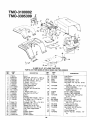
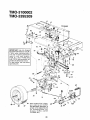
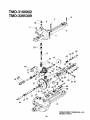
TMO-3100002
-
TMO 3395309
"
27
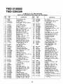
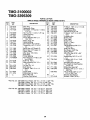
16 AND 18 H.P. 42" LAWN TRACTORS
PARTS LIST FOR MODELS TMO-3100002 AND TMO-3395309
REF.
NO.
PART
NO.
1
2
3
4
5
6
7
8
9
10
11
12
13
14
15
16
17551A
738-0724
736-0342
_710-0258
736-0329
712-0287
749-0812
731-1099A
712-0380
731-1097A
736-0119
712-0267
725-0963
725-1649
710-0703
710-0599
17
18
19
20
21
22
23
24
25
736-0173
726-0233
712-0185
710-0118
17632
731-1096A
725-0267
725-0201
746-0614A
DESCRIPTION
Hood
Shld. Bolt .375" Dia. x .125" Lg.
Fl-Wash.
,28" I.D. x .75" O.D.
Hex Bolt I/4-20 x .62" Lg.*
L-Wash. I/4" I.D.*
Hex Nut I/4-20 Thd.*
Grille Support Rod
Headlight Lens
Flange L-Nut 114-28 Thd.
Grille
L-Wash. 5/I 6" I.D.*
Hex Nut 5/16-18 Thd.*
Lamp
Socket
Carriage Bolt I14-20 x .75" Lg.
Hex Wash. Hd. TT-Tap Scr.
114-20 x .5" Lg.
Fl-Wash..281"
I.D. x .73" O.D.
Bolt Retainer 114" I.D.
Speed Nut I/4-20 Thd.
Hex Bolt 5/16-18 x ,75" Lg.
Gas Tank Support Brkt.
Dash
Ignition Switch
Ignition Key
Choke Control
iREF.
PART
NO. _
NO.
i
I
26
725-0634
27
725-0925
28
15821
29
15822
30
710-0607
32
710-0286
33
710-0167
34
35
38
17324A
17871
710-0726
40
41
42
17286A
831-0823A
710-0779A
43
I 44
45
746-0634
777-9206
710-0603
E
46
47
17782
710-0642
DESCRIPTION
Light Switch
Ammeter
Grille Mtg. Brkt.--L.H.
Grille Mtg. Brkt.--R.H.
Hex Wash. Hd. Tap Scr, 5/16 x
.5" Lg.
Truss Mach. Scr. 1/4-20 x .5" Lg.
(TMO-3395309)
Carriage Bolt 1/4-20 x .62"
(TMO-3100002)
Fender (TMO-3100002)
Fender (TMO-3395309)
Hex Wash, Hd AB-Tap Scr.
5/16 x .75" Lg.
Shift Cover
Throttle Box Ass'y.
Truss Mach. AB-Tap Scr.
#10 x .5" Lg.
Throttle Control Wire
Grille Reflector Label
Hex Wash. Hd. B-Tap Scr.
5/16-18 x .5" Lg.
Choke Retainer
Hex TT-Tap Scr. 1/4-20 x .75"
Lg.
i
i
i
2O
TMO-3100002
TMO-3395309
8
i
II
22
6?
26 _
/
6
3Z
4
/
413
J
!
30
51
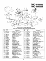
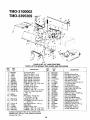
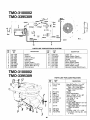
16 AND 18 H.P. 42" LAWN TRACTORS
PARTS LIST FOR MODELS TMO-3100002 AND TMO-3395309
REF,
NO.
PART
NO.
REF,
DESCRIPTION
PART
NO.
NO.
i
DESCRIPTION
I
736-0159
710-1208
3
4
6
7
8
9
10
11
12
13
14
16
21
22
738-0155
738-0145
736-0141
15607D
751-3071
751-0555
726-0209
751-0535-26
726-0205
712-0138
712-0287
736-0329
732-0672
738-0526
710-0227
23
24
25
26
726-0139
17621
710-0623
710-0726
28
29
30
32
33
7!0-0134
17770
761-0168A
731-0909
731-0910
710-0323
34
35
36
17620C
736-0169
726-0278
5
FI-Wash. 344" I.D. x .875"
Hex Wash. Hd. Tap Scr.
5/16-18 x 3.25" Lg.
Shld. Bolt .437" Dia. x •162"
Shld. Bolt .50" Dia. x .84"
Spr-Wash..445"
ID. x .75
Seat Pivot Bracket
Fuel Cap
Fuel Tank
Tie Strap
Fuel Line
Hose Clamp
Hex Nut 1/4-28 Thd.
Hex Nut 1/4-20 Thd."
L-Wash.
1/4" I.D.
Compression
Spring
Running Board Rod
Hex Wash. Hd. AB-Tap Scr.
#8 x .50" Lg.
Speed Nut #10Z
Front Pivot Brkt.
Hex Tap Scr. 3/8-16 x .75"
Hex Wash• Hal. AB-Tap Scr.
5/16 x .75" Lg.
Carriage Bolt 1/4-20 x .62"*
Running Board (R.H & L.H.)
, Blade Brake Ass'y.
: Rubber Foot Pad--L.H.
Rubber Foot Pad--R.H.
i Truss Mach. Scr. 5/16-18 x
i
.75" Lg*
Lower Frame
L-Wash. 3/8" I.D.*
Insulator Boss Plate
I
37 i 736-0463
38i 710-0118
39i
17622B
41i
712-0798
42!
732-0581B
43!
731-1200
44!
725-1430
17623
17286A
725-0759
726-0279
17951
17953
712-0267
736-0119
17239A
757-0338
757-0360
55
17960
56_ 738-0296
57_ 725-1303
58 E,722-0160
5g 710-0650
45
46
47;
48
49
50
51
52
53
54
62
726-0320
725-1439
17952
710-0351
63
65
66
67 748-0347
68 i 710-1221
69i 710-0412
i
21
FI-Wash..25"
I.D. x .625" O.D.
Hex Bolt 5/16-18 x .75" Lg.*
Upper Frame--R.H.
Hex Nut 3/8-16 Thd.*
Extension
Spring 5.31" Lg.
Battery Cover
12-V Battery (275 Cold Crank
Amps)
Upper Frame--L.H.
Shift Cover
Reverse Safety Switch
Insulator
Plate
Seat Pivot Brkt. Support--L.H.
Hitch Plate
Hex Nut 5/16-18 Thd.*
L-Wash
5/16" I.D.*
Seat Lift Brkt.
Seat (TMO-3395309)
Seat (TMO-3100002)
Seat Pivot Brkt. Support--R.H.
Shld. Bolt .437" Dia. x .268"
Spring Switch
Bushing
Hex Wash. TT-Tap Scr. 5/16-18
x 7/8" Lg.
Insulator Nut Plate
Safety Switch (Seat)
Battery Tray
Truss Mach. B-Tap Scr.
#10 x .5" Lg.
Spring Spacer
Pan Hd. Cutting Scr. 5/16-18 x
.75" Lg.
Hex Bolt 1/4-28 x .75" Lg.
TMO-3100002
TMO-3395309
To Engine. //7
1. 7
/'
,/
28
67
38
31
37
\
33
\,
34
22
/
26
TMO-3100002
TMO-3395309
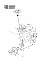
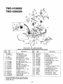
16 AND 18 H.P, 42" LAWN TRACTORS
PARTS LIST FOR MODELS TMO-3100002 AND TMO-3395309
REF.
NO,
1
[
4
5
6
9
0
PART
NO.
731-0220
712-0237
736-0242
731-0806A
731-0954
737-0280
17198A
738-0141
710-0152
!750-0535
4
15
!6
7
18
736-0169
710-0726
711-0788
17621
738-0527
Ig
7!2-0798
736-0169
712-0237
__2 16481A
t3 710-0772
__4 741-0487A
683-0002
17585
._7 712-0241
._
736-0169
__c 723-3018
30
747-0753
DESCRIPTION
NO.
Steering Wheel Cap
Hex L-Nut 5/16-24 Thd.
Belleville Wash..345" I.D.
Steering Wheel
Steering Bellow
Grease Fitting
Retainer Plate
Shoulder Bolt .437" Dia. x
.35 Lg. 5/16-18 Thd.
Hex Bolt 3/8-24 x 1.0" Lg.
(Grade 5)
Spacer .380" I.D. x .625"
O.D. x .227
L-Wash. 3/8" I.D.*
Hex Wash. Hd. Self-Tap Scr.
Steering Drag Link
Front Pivot Brkt.
Shoulder Bolt .498" Dia. x
2.04 Lg. 3/8-16 Thd.
Hex Nut 3/8-16 Thd.*
L-Wash. 3/8" I.D.*
Hex Cent. L-Nut 5/16-24 Thd
Steering Arm Front Axle
Hex Bolt 5/16-24 x 200"
Lg. (Grade 5)
Hex Ftg. Brg .632 I.D.
Pivot Bar Ass'y.
Front Axle Ass'y.--LH.
Hex Nut 3/8-24 Thd.*
31
32
REF.
33
L-Wash. 3/8" I,D.*
Ball Joint 3/8-24 Thd.
Tie Rod
34
35
36
37
38
39
40
42
43
44
45
46
47
48
49
50
51
52
53
54
58
59
i
60
t
61
64
66
67
68
]
PART
NO.
DESCRIPTION
Hex Jam Nut 3/8-24 Thd.*
Front Axle Ass'y,--R.H,
Wheel Ass'y. Comp.
Tire Only
Front Wheel Rim Only
Bearing
FI-Wash..635 I.D. x 1.59" O.D.
Front Wheel Hub Cap
Cotter Pin 1/8" Dia. x 1.25"*
FI-Wash, .640" I.D. x 1.24" O.D.
Push Cap 5/8" Dia. Rod
Hex Jam Nut 3/8-24 Thd.
Hex L-Bolt 5/16-18 x .62"*
L-Wash. 5/16" I.D.*
FI-Wash..33" I.D. x 1.25" O.D.
Spacer (Plastic)
Hex Cent. L-Nut 3/8-24 Thd,
L-Wash. 3/8" I.D.*
Hex Cent. L-Nut 5/16-18 Thd.
L-Wash. 5/16" I.D.*
Steering Gear Segment
Hex Fig. Brg..634 I.D.
FI-Wash. (Hardened)
Steering Shaft
Wave-Wash..32"
I.D. x .62" O.D
FI-Wash. (Hardened)
Drag Link Ball Joint 3/8-24 Thd.
712-0711
17584
634-0056
734-0864
634-0024
741-0487A
736-0285
731-0484A
714-0470
736-0187
726-0214
712-0446
710-0538
736-0119
736-0343
750-0532
7t2-0214
736-0169
712-0158
736-0119
717-0622A
741-0225
736-0187
738-0743
736-0271
736-0187
723-3018
736-0607
736-0356
710-0459
734-0255
737-0211
Ext. L-Wash. 5/16" I.D.
Bell-Wash..39"
I.D, x 1.38" O.D.
Hex Bolt 3/8-24 x 1.5" Lg. (Gr. 5)
Air Valve
l
Grease Fitting
j
NOTE:
Specifications
notice or obligation,
*Common
Hardware--May
be purchased
locally.
IMPORTANT:
DO NOT order parts by reference
number (Ref. No.),
PARTS
TMO-3100002
TMO-3395309
REF.
NO.
1
2
3
4
5
6
7
8
9
10
11
12
14
17
19
20
23
PART
NO.
710-0924
16194
720-0218
16192
736-0192
711-0198
738-0155
747-0503A
714-0111
736-0226
736-0119
712-0267
732-0303
736-0140
736-0329
712-0287
subject
LIST FOR
to change
LAWN
without
TRACTORS
DESCRIPTION
Truss Mach. Scr. 1/4-20 x
.75" Lg.
7-Speed Selector Plate
Shift Knob
Speed Selector Lever Ass'y.
Flat Washer .53" I.D. x .93"
Ferrule 3/8-24 x .37" Dia.
Shoulder Bolt
Speed Control Link
Cotter Pin 3/32" Dia. x 1.0"*
FI-Wash..469" I.D. x .88"
L-Wash. 5/16" I.D.*
Hex Nut 5/16-18 Thd.*
Spring .38" O.D. x 3.18" Lg.
FI-Wash..385" I.D. x .62"
L-Wash. 1/4" I.D.*
Hex Nut 1/4-20 Thd.*
TMO-3100002
TMO-3395309
42
26
TOEN61NE
/
88
/02
B
89',
3-
11
IMPORTANT:
Use only Original
Equipment
Manufacturer
(O.E.M.)
V-belts
when
replacing
belts.
They are of special
construction
(type
of cord,
cord
location,
length,
etc.). Use of V-belts other
than O.E.M.
belts generally
will
provide only temporary service.
For best results, use only factory
approved
parts.
25
71
\
56
Note: If brand of tire is important, order by part number
and description
(description
is
printed on the sidewall
of tire)
[i.e. Armstrong
Super
Turf,
Goodyear
Softrac,
Carlisle
Turf Saver, etc.].
24
4_
36
\
I09
128
TMO-3100002
TMO-3395309
16 AND 18 H.P. 42" LAWN TRACTORS
PARTS LIST FOR MODELS TMOo3100002 AND TMO-3395309
REF.
NO.
PART
NO.
2
3
5
10
17840
17962
736-0119
710-0502A
11
13
14
15
16
17
18
19
20
21
22
23
24
25
26
27
28
17620C
712-0287
736-0329
710-0604
17358C
736-0242
712-0267
710-0190
714-0114
756-0424
736-0322
736-0171
710-0757
754-0280
710-0118
17963
741-0591
29
712-0241
30
17643
31
736-0169
32
712-0241
33
17629A
34 732-0556
35 i714-0149B
36 750-0802
39 712-0138
40
710-0776
41 i711-0747
42
!736-0222
43
710-0599
44
45
46
17715A
j736-0117
1710-0351
47
48
51
53
54
55
56
17686A
i735-0196
17705
732-0264
732-0413
710-0176
734-1675
734-1596
734-0603A
734-0255
710-0627
732-0454
736-0275
710-0428
57
58
59
6!
63
64
DESCRIPTION
Transaxle Mtg, Brkt.
Switch Plate
L-Wash. 5/16" I.D.*
Hex L-Wash. Tap Scr. 3/8-16 x
1.5" Lg.
Lower Frame Ass'y.
Hex Nut 1/4-20 Thd.*
L-Wash, 1/4" I.D.*
Hex TT-Tap Scr. 5/16-18 x .62"
Belt Guard Brkt. Ass'y.
Bell-Wash..345"
I.D. x .88"
Hex Nut 5/16-18 Thd.*
Hex Bolt 5/16-18 x 4.0"*
Sq. Key 1/4" x 1/4" x 2.00"
Engine Pulley
FI-Wash. 7/16" I.D. x 1.25"
L-Wash. 7/16" I.D.*
Hex Bolt 7/16-20 x 1.50" Lg.
Variable-Speed Belt
Hex Bolt 5/16-18 x .75" Lg.
Bearing Shaft Bracket Ass'y.
Flanged Nyliner Brg. 5/8"
I.D. x .88" Lg.
Hex Nut 3/8-24 Thd.*
Idler Bracket
L-Wash. 3/8" I.D.*
Hex Nut 3/8-24 Thd.*
Transaxle Support Brkt.
Ext. Spring 94" O.D, x 7_58"
Inter. Cotter Pin
Spacer 63" I.D.
Hex Nut 1/4-28 Thd.
Hex AB-Tap Scr. 1/4" x .62" Lg,
Belt Guard Pin
Ext. L-Wash. 1/4" I.D.
Hex Wash. Hd. S-Tap Scr.
1/4-20 x .50" Lg.
Clutch/Brake Pedal Ass'y.
FI-Wash
Truss Mach. Scr. B-Tap Scr.
#10 x .5" Lg.
Brake Rod Ass'y.
Foot Pad
Shift Lever Ass'y.
Ext. Spring .38" O.D, x 2.5"
Ext. Spring .59" O.D, x 7.08"
Hex Bolt 5/16-18 x 2.75"*
Wheel Ass'y. Comp.
Tire Only
Wheel Rim Only
Air Valve (Service Only)
Hex Bolt 5/16-24 x .75" Lg.*
Brake Return Spring Anchor
FI-Wash..34"
I.D. x .68" O.D.
Hex Bolt 1/4-28 x 1.25" Lg.*
REF.
NO.
PART
NO.
65
66
67
732-0568
732-0384
16554A
68
69
701
711
72
731
74
75
76
77
78
79
80
81
82
741-0419
714-0111
748-0234
747-0530A
741-0405
720-0232
756-0437
656-0004
736-0427
712-3035
710-0539
754-0370
716-0114
736-0355
717-0800A
84
85
86
16354B
732-0525
17668
17669
88
89
9O
92
93
94
97
98
99
100
101
102
725-1426
17630
736-0414
710-1223
725-3169A
738-0755
736-0105
738-0569
736-0331
736-0256
714-0470
710-0604
107
108
109
111
112
113
115
116
119
120
121
122
128
17860
714-0470
711-0198
710-0195
736-0270
17707
736-0140
741-0404
710-0427
756-0217
736-0280
712-0798
710-0650
129
710-0726
25
DESCRIP_ON
Ext. Spring
Ext. Spring .62" O.D. x 6.12"
Variable Speed Torque
Brkt. Ass'y.
Flanged Bearing
Cotter Pin 3/32" Dia.*
Shoulder Spacer .27" Lg.
Speed Control Link
Truss Bearing .56 Dia. x 1.25"
Shift Knob
Fl-ldler Pulley 3.25" x .75"
"V" Pulley
Bell-Wash..56"
I.D. x 1.125"
Hex Jam Nut 5/16-18 Thd.
Hex Bolt 3/8-24 x 1.75" Lg.
Variable Speed Belt
Snap Ring .56" Dia.
FI-Wash.
Variable Speed Pulley
Ass'y. 5" O.D.
Variable Speed Brkt. Ass'y.
Comp. Spring--Clip
Axle Support Brkt.--R.H.
Axle Support Brkt.--L.H.
(Not Shown)
Solenoid
Shift Lever Bracket
Teflon Washer .565" I.D.
Hex Bolt 1/4-20 x 3.5" Lg.
Safety Switch. (Clutch)
Shld. Bolt 3/8-24 x 3.12" Lg.
Bell-Wash..38"
I.D. x .88"
Shaft .56" Dia. x 3.875" Lg.
Bell-Wash..39"
I.D. x 1.12"
FI-Wash..64" I.D. x .94"
Cotter Pin 1/8" Dia. x 1.25"
Hex Wash. Hd. Scr. 5/16-18
x .62" Lg.
Pedal Bracket
Cotter Pin 1/8" Dia. x 1.25"
Ferrule
Hex Bolt 1/4-28 x .50" Lg.
Bell-Wash..265"
I.D, x .75"
Shift Lever Link Ass'y.
FI-Wash..385" I.D. x .62"
Needle Brgs. (2 Req'd.)
Hex Bolt 3/8-16 x 1.25" Lg.
Fl-ldler w/Flanges 2.75" O.D.
FI-Wash..39" I.D. x 1.12" O.D.
Hex Nut 3/8-16 Thd.
Hex Wash. TT-Tap Scr. 5/16-18
x .75" Lg.
Hex Wash. AB-Tap Scr. 5/16-18
x .75" Lg.
TMO-3100002
TMO-3395309
39
21
2
\
25
16 AND 18 H.P. 42" LAWN TRACTORS
PARTS LIST FOR MODELS TMO-3100002 AND TMO-3395309
REF.
NO.
PART
NO.
1
2
3
4
5
6
7
8
9
10
12
13
14
09735A
17640
17641
17710
!4800A
14804A
748-0331
736-0264
736-0119
712-0267
714-0470
736-0256
732-0412A
15
t6
08540
710-0604
17
18
748-0176
710-1238
19
20
21
23
24
710-0118
17730
17622B
736-0267
736-0160
DESCRIPTION
REF.
NO.
25
26
27
28
29
30
31
32
33
34
35
36
37
38
39
40
41
42
43
44
45i
46i
47i
48i
Connecting Rod
Pivot Link Ass'y.--L.H.
Pivot Link Ass'y.--R.H.
Deck Hanger Link Ass'y.
Deck Hanger Link Ass'y.
Deck Hanger Link Ass'y,
Shld. Spacer .318" I.D.
FI-Wash..344" I.D. x .62" O.D.
L-Wash, 5/16" I.D.*
Hex Nut 5/16-18 Thd.*
Cotter Pin 1/8" Dia.
FI-Wash..635" ID. x 1.0" O.D.
Deck Lift--Down Stop (Incl.
Ref. 15)
Knob
Hex Wash. Tr-Tap Scr.
5/16-18 x .75" Lg.
Flange Brg..63" I.D.'l"
Hex Wash. Hd. Scr. 5/16-18
x .875" Lg.
Hex Bolt 5/16-18 x .75" Lg.
Index Brkt.
Upper Frame--R.H,
FI-Wash..385" I.D. x .87" O,D.
FI-Wash. ,531" I.D, x .93" O.D.
*Common
Ha_ware---May
be purchased
locally.
IMPORTANT:
DO NOT order pa_s by reference
number (Ref. No.).
26
PART
NO.
728-0272
738-0526
710-3007
14802A
711-0723A
17712
712-3066
711-0841
17637A
725-0803C
714-0145
732-0637
17636A
738-0670
732-0638
720-0233
17675
738-0669
747-0598
17624
732-0556
17623
741-0313
17128
DESCRIPTION
Clamp
Running Board Rod
Hex Wash, Hal. Tap Scr.
Link Deck Lift Ass'y.
Adj. Ferrule 3/8-24 Thd,
Adj. Deck Lift Link
Hex Nut 1/2-20 Thd. (Gr. 5)
Lift Link Adjuster
Lift Shaft Ass'y.
Safety Switch (Deck)
Inter. Cotter Pin 3/8" Dia.
Extension Spring
Stabilizer Bracket
Shaft 112" Dia. x 10.28" Lg.
Extension Spring
Grip (Lift Handle)
Deck Lift Handle Ass'y.
Shaft 3/8" Dia. x 9.34" Lg.
Disengagement Rod
Stabilizer Shaft Ass'y.
Extension Spring 7.58" Lg.
Upper Frame--L. H,
Flange Brg, .632" I.D.
Spring Retainer Brkt.
i
I
,
TMO-3100002
TMO-3395309
9
20"-
23
.
20_t
6 II**
16 AND 18 H.P. 42" LAWN TRACTORS
PARTS LIST FOR MODELS TMO-3100002 AND TMO-3395309
REF.
NO.
PART
NO.
3
17600A
813-06119
4
6
7
17664
710-0152
710-0599
8
9
10
11
13
14
17
18
710-0258
710-0888
711-0792
712-0123
712-0181
712-0287
734-0973
736-0105
19
20
22
23
25
736-0119
736-0217
i738-0373
742-0499A
748-0300
REF.
NO,
DESCRIPTION
42" Deck Ass'y.
42" Deck Ass'y. Comp.
(For Service Only)
Belt Guard Deck
Hex Bolt 3/8-24 x 1.0" Lg.
Hex Wash. Hd. TT-Tap Scr.
1/4-20 x .5" Lg,
Hex Bolt 1/4-20 x .62"
Hex Bolt Special 5/1,6-24 x 1.0"
Hinge Pin
Hex Nut 5/16-24 Thd.*
Hex Top L-Nut 3/8-16 Thd.
Hex Nut 1/4-20 Thd.*
Deck Wheel--5"
Bell-Wash..40"
I.D. x .88"
OD.
L-Wash. 5/16" I.D.*
L-Wash. 3/8" I.D.--H.D.
Shld. Bolt .498" Dia. x 1.53"
High-Lift Blade
Blade Adapter
*Common Hardware---May be purchased locally.
IMPORTANT: DO NOT order parts by reference
number (Ref. No.).
27
PART
NO.
26
27
28
33
35
37
39
42
52
53
54
55
754-0371A
736-0270
09322
710-0157
712-0318
736-0158
717-0906
756-0556
703-1693
732-0602
726-0106
731-1032
56
57
58
59
60
61
62
710-0157
17493A
736-0242
710-0167
17861A
17961
712 0271
DESCRIPTION
V-Belt
Bell-Wash. 1/4" I.D.
Brake Disc
Hex Bolt 5/16-24 x .75" Lg
Hex Jam Nut 5/8-18 Thd.
L-Wash. 5/8" I.D.*
Blade Spindle Ass'y. Comp.
5.5" Dia. Pulley
Hinge Mtg. Brkt.
Torsion Spring
Push Nut
Chute Ass'y. Comp. (Incl. Ref.
10, 52, 53, 54, 55)
Hex Bolt 5/16-24 x .75" Lg.
Deck Hanger Channel
Bell-Wash_ .345" I.D. x .88"
Carr. Bolt 1/4-20 x ,5" Lg.
Deck Skirt Ext.--Long
Deck Skirt Exl.--Short
Hex Seres Nut 1/4-20 Thd.
TMO-3100002
TMO-3395309
22
26
13
46
1-/8
SINGLE SPEED TRANSAXLEmR.H.
MODEL 618-0073
28
TM0-3100002
TMO-3395309
PARTS LIST FOR
SINGLE SPEED TRANSAXLE RIGHT HAND 618-0073
REF.
NO.
PART
NO,
1
2
3
732-0614
716-0171
710-1026
4
5
8
10
710-0809
719-0314
711-0861
736-0335
11
12
13
14
717-0633
716-0171
711-0943
741-0336
15
16
17
8
9
20
21
717-1362
717-1363
718-0228
717-1020
716-0184
741-0589
710-0862A
22
23
717-O539
741-0340
24
25
26
721-0179
750-0767
736-0445
27
28
29
32
711-0918
717-1252
t*
REF.
NO,
DESCRIPTION
Wire Ring
Retaining--Ring
Hex Wash. TT-Tap Scr. 1/4-20 x
1.75" Lg.*
Hex Tap Scr. 1/4-20 x 1.25" Lg.
Upper Housing
Input Shaft
Thrust Washer 5/8" I.D. x .
1.25" O,D.
Pinion Input 14T
Retaining Ring
Drive Shaft--R.H. Brake
Flange Brg. 5/8" I.D. x 3/4"
Lg.
Bevel Gear 42T Small I.D.
Bevel Gear 42T Large I.D.
Clutch Collar
Miter Gear 15T (H.D.)
Snap Ring
Thrust Bearing
Pan Head Scr. 1/4-20 x .50"
Lg. w/Patch
Axle R.H. Ass'y.
Sleeve Bearing 3/4" I.D. x
1.0" Lg,
Oil Sea{ 3/4" I.D.
Axle Spacer
FI-Wash..760" I.D. x 1.5"
O.D.
Cross Shaft
Differential Can Ass'y.
Parl of Ref. 28
Washer (See Below)
PART
NO.
33
34
35
38
39
736-0445
719-0313
718-0150
712-0273
736-0371
40
411
42
43
44
45
46
717-0700
761-0198
717-0682
717-0678
717-0538
761-0202
741-0337
48
49
50
51
61_-0011
741-0862
732-0863
714-0169
52
741-0335
54
736-0349
55
56
741-0343
710-1206
57
58
717-1364
736-0349
736-0495
6O
737-0148
i
**Ref. No. 32 736-0495
736-0336
736-0494
736-0337
Thrust Wash.
FI-Wash. 5/8"
Thrust Wash.
FI-Wash. 5/8"
5/8"
I.D.
5/8"
I.D.
I.D.
x 1"
I.D.
x 1"
**Ref. No. 60 736-0492
736-0493
736-0351
736-0445
FI-Wash, .76"
FI-Wash..76"
FI-Wash..76"
FI-Wash..76"
I.D.
I.D.
I.D.
I.D.
x
x
x
x
x 1" O.D. x .025" Thk.
O.D. x .030" Thk.
x 1" O.D. x .035" Thk.
O.D. x .040" Thk.
1.5"
1.5"
1.5"
1.5"
O.D,
O.D.
O.D.
O.D.
x
x
x
x
.010"
.020"
.030"
.060"
29
Thk.
Thk.
Thk.
Thk.
DESCRIPTION
FI-Wash..760" I.D. x 1.5" O.D.
Lower Housing
Anti-Rotation Brkt.
Hex Nut 5/16-24 Thd.
FI-Wash..344" I.D. x .875"
O.D.
Actuating Arm
Brake Yoke
Puck Plate
Brake Puck
Axle L.H. Ass'y.
Brake Disc
Flange Bearing 5/8" I.D. x
15/16" Lg.
Shift Fork Ass'y.
Ball Detent .250" Dia.
Spring Detent
#9 Hi-Pro Key 3/16" x 3/4"
Dia. HT
Needle Brg. 5/8" I.D. x 1/2"
Lg.
FI-Wash. 5/8" I.D. x 1" O.D.
x .020 Thk.
Actuating Pin 5/16" Dia.
Hex Wash Hd. Self-Tap Scr.
1/4-20 Thd.
Differential Gear 58T
FI-Wash. 5/8" I,D. x 1" O.D. x
.020 Thk.
Thrust Wash. 5/8" I.D. x 1"
O.D. x .025" Thk,
Washer (See Below)
Grease_Shell
(15 oz.)
TMO-3100002
TMO-3395309
i1E
1
13
Black
•
Yellow
_
LBlack
_.
Blue
_ L_White
_
8
PARTS LIST FOR ELECTRICAL
PART
NO.
1
2
3
4
5
6
7
8
9
725-1438
725-1426
725-1625
725-0634
725-0925
725-0267
725-3169A
725-0562
629-0080
Blue
Green
lO
REF.
NO.
_i_ _
Yellow
PART
NO,
REF.
DESCRIPTION
NO.
10
11
12
13
14
15
16
17
Battery
Solenoid
Fuse 7.5 Amps
Light Switch
Ammeter
Ignition Switch
Safety Switch (Clutch)
Electric Wire 32.5" Lg.
Wire Harness
SYSTEM
726-0197
725-0803C
725-0759
725-1649
725-0963
725-1303
725-0980
725-1439
731-1284
DESCRIPTION
Cable Tie
Safety Switch (Deck)
Safety Switch (Reverse)
Socket
Bulb (Headlight)
Safety Switch (Seat)
Ground Wire 7.5" Lg.
Safety Switch (Seat)
Harness Conduit (Not Shown)
TMO-3100002
TMO-3395309
PARTS
REF,
NO.
1
2
2
NO,
710-0776A
17450
751-0474
16934
736-0170
712-0267
731-0511-12
737-0164
737-0143
16 H.P.
18 H.P.
12
13
14
3
30
TRACTORS
PART
17449
3
4
5
6
7
8
9
11
LIST FOR LAWN
726-0272
736-3067
710-0779A
DESCRIPTION
Hex AB-Tap Scr. 1/4 x .62"
Muffler Heat Shield Mtg.
Brkt.--R.H. (Not Shown)
Muffler Heat Shield Mtg.
Brkt.--L,H.
Muffler
Front Heat Shield
Spec, L-Wash. 5/16 x .88"
Hex Nut 5/'16-18 Thd.
Trim Strip 12" Lg,
Pipe Nipple
Oil Drain Cap
Engine-B&S 402707-1511-01
(TMO-3395309)
Engine-B&S 422707-1510-01
(TMO-3100002)
Clamp
FI-Wash..188" I.D. x .438"
Truss Mach. AB-Tap Scr. #10
x .5" Lg,
14
USE THIS SHEET AS A GUIDE TO DETERMINE
i
| _
SIGHT AND HOLD THIS LEVEL WITH A VERTICAL TREE
• ... I
I....
l_'_
I'_._
SLOPES WHERE YOU MAY NOT OPERATE SAFELY.
"'" ",...
......
I_
I
I
I
........
I_
I
.
l
'
I
....
-"
•
A POWER POLE
............
A CORNER OF A BUILDING
I
,-:,.
4)
i _>_
I ,1
_,
I_=
nb
_
•
4)
' _
!
_
L
= .%'-
•
4)
;P,
I
,_.
;-
)
....
.
I _
*'*o
.....
OR A FENCE POST
I
",..
_-U O_
*",;7
O0.r.,.
.... "._NT#u..
-,,,,:
,
I
too _0_
""" .....
r,)
15 °
Do not mow on inclines with a slope in excess of 15 degrees (a rise of approximately 2-1/2 feet every 10 feet). A
riding mower could overturn and cause serious injury. If operating a walk-behind mower on such a slope, it is
extremely difficult to maintain your footing and you could slip, resulting in serious injury.
Operate RIDING mowers up and down slopes, never across the face of slopes.
Operate WALK-BEHIND mowers across the face of slopes, never up and down slopes.
SERVICE
NATIONWIDE
Mor,cgommy Wind
HOW TO OBTAIN.
REPLACEMENT
PARTS AND SERVICE
The merchandise you have purchased from us has been carefully
engineered
and manufactured
under Montgomery
Ward's rigid
quality standards and should give you satisfactory and dependable
operation. However, like all mechanical merchandise, Jt may occasionally require adjustment, replacement parts or maintenance.
Toll Free Parts Sales Center
When you need a replacement part or accessory for a major appliance, home electronic item or lawn and garden product that is not
under warranty or covered by a service contract or if you need the
location of the nearest service facility, call our Parts Sales Center
toll free 1-800-323-1965.
Provide
lhe following:
1. Model,
serial number
model
2.
Also
give the part
that came
Replacement
requested,
all of the
other
data
shown
on
the
number
Parts
pnces
MODEL
or numbers
as shown
in the parts
list
with Ihe product.
wil!
be
made
will be quoted
H you order parts by mail,
from the shipping point.
UNIT
and
plate.
you
available
in advance
will
pay
at current
when
prices.
If
not listed.
the transportation
charges
NO.
UNIT SERIAL NO.
ENGINE MODEL
NO.
TYPE NO.
CODE NO.
PART NO. 770-8087H
133P670G088
132-670G088
PRINTED
IN U.S.A.