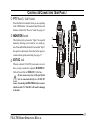
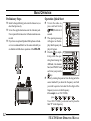
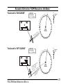
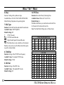
1
AIR BAND TRANSCEIVER
VXA-700
Operating Manual
SPIRIT
CONTENTS
Important Notice! ........................................................... 1
Introduction .................................................................... 2
Control & Connectors ................................................... 3
Top Panel .............................................................................. 3
Front Panel ........................................................................... 4
Side Panel ............................................................................. 5
Keypad .................................................................................. 6
Before You Begin ........................................................... 8
Precautions ........................................................................... 8
How to Install the Quick Draw Clip ................................... 8
Installation of FNB-80LI Battery Pack .............................. 9
Battery Charging .................................................................. 9
Installation of FBA-23 Alkaline Battery Case ................. 10
Battery Life Information .................................................... 11
AC Operation Using NC-72B/C ....................................... 11
Basic Operation ........................................................... 12
Preliminary Steps ............................................................... 12
Operation Quick Start ........................................................ 12
Squelch Adjustment ........................................................... 13
Accessing the 121.5 MHz Emergency Frequency ........... 14
Tuning Methods ................................................................. 14
Transmission ...................................................................... 15
Reception of Weather Channel Broadcasts ...................... 16
Monitor Key ....................................................................... 17
ANL (Automatic Noise Limiter) Feature ......................... 17
LOCK Function ................................................................. 18
Beep On/Off ....................................................................... 18
Receive Battery Saver Setup ............................................. 19
Memory Operation ....................................................... 20
Memory System Operation ............................................... 20
Memory Storage ................................................................. 20
Recalling the Memories..................................................... 21
Scanning Operation .................................................... 22
Basic Scan .......................................................................... 22
Channel-Skip Scanning ..................................................... 23
Programmable (Band Limit) Memory Scan (PMS) ........ 23
Dual Watch Operation ................................................. 24
Priority Dual Watch Operation ................................... 25
Spectrum Scope Monitor ............................................ 26
Advance Operation (VOR Navigation: AIR Band) ... 28
To Select the VOR Mode .................................................. 29
Flying to a VOR Station .................................................... 30
Entering a Desired Course ................................................ 32
Position Cross-checking .................................................... 33
Split Operation ................................................................... 34
Advanced Operation (Amateur Radio Band) ........... 35
Repeater Operation ............................................................ 35
CTCSS Operation .............................................................. 37
DCS Operation ................................................................... 39
ARTS (Automatic Range Transponder System) Operation ......... 40
Miscellaneous Setting ................................................. 42
Changing the Channel Step ............................................... 42
Changing the Operating Mode .......................................... 42
Automatic Power-Off (APO) Feature) ............................. 42
Transmitter Time-Out Timer (TOT) ................................. 43
Programming the Key Assignments ................................. 44
Display Customization ...................................................... 45
TX/BUSY Indicator Customization ................................. 46
Field Programming Mode ........................................... 47
CPU Resetting .............................................................. 48
Timer Mode ................................................................... 48
Menu (“Set”) Mode ...................................................... 49
Specifications ............................................................... 60
Accessories & Options ............................................... 62
Incase of Difficulty ....................................................... 64
IMPORTANT NOTICE!
FCC RF Exposure Compliance Requirements for Occupational Use Only:
This Radio has been tested and complies with the Federal Communications Commission (FCC) RF exposure limits for
Occupational Use/Controlled exposure environment. In addition, it complies with the following Standards and Guidelines:
r FCC 96-326, Guidelines for Evaluating the Environmental Effects of Radio-Frequency Radiation.
r FCC OET Bulletin 65 Edition 97-01 (1997) Supplement C, Evaluating Compliance with FCC Guidelines for Human
Exposure to Radio Frequency Electromagnetic Fields.
r ANSI/IEEE C95.1-1992, IEEE Standard for Safety Levels with Respect to Human Exposure to Radio Frequency
Electromagnetic Fields, 3 kHz to 300 GHz.
r ANSI/IEEE C95.3-1992, IEEE Recommended Practice for the Measurement of Potentially Hazardous Electromagnetic Fields - RF and Microwave.
¦ This radio is NOT approved for use by the general population in an uncontrolled environment. This radio is
restricted to occupational use, work related operations only where the radio operator must have the knowledge
to control its RF exposure conditions.
¦ When transmitting, hold the radio in a vertical position with its microphone 1 to 2 inches (2.5 to 5 cm) away
from your mouth and keep the antenna at least 1 inch (2.5 cm) away from your head and body.
¦ The radio must be used with a maximum operating duty cycle not exceeding 50%, in typical Push-to-Talk
configurations. DO NOT transmit for more than 50% of total radio use time (50% duty cycle). Transmitting
more than 50% of the time can cause FCC RF exposure compliance requirements to be exceeded.
The radio is transmitting when the red LED on the top of the radio is illuminated. You can cause the radio to
transmit by pressing the P-T-T button.
¦ Always use Vertex Standard authorized accessories.
NOTICE
r There are no user-serviceable points inside this transceiver. All service jobs must be referred to your Authorized
Service Center.
r Amateur Radio License required for operation on Amateur Radio frequencies.
VXA-700 SPIRIT OPERATING MANUAL
1
INTRODUCTION
The Vertex Standard VXA-700 Spirit is a compact, stylish, solid hand-held transceiver providing communication (transmit and receive) capability on the International Aircraft Communication Band (“COM” band: 118 ~ 136.975 MHz), and it
additionally provides VOR and CDI navigation features on the “NAV” band (108 ~ 117.975 MHz). What’s more, it also is
operational on the Amateur Radio 144 MHz band, for those operators appropriately licensed by the FCC (or the appropriate licensing authority in your country).
The VXA-700 includes Temperature display with our exclusive Omni-Glow™ display back-light for minimal degradation
of your night vision, NOAA weather band monitoring, 8-character Alpha/Numeric Display, 102 Memory Channels, and 90
“Book Memory” Channels.
We recommend that you read this manual in its entirety, so as to understand the many features of the VXA-700 completely.
Keep this manual handy, so you may use it for reference.
NOTE: The VXA-700’s VOR and CDI Navigation features are supplemental aids to navigation only, and are not
intended to be a substitute for accurate (primary) VOR/CDI or landing service equipment.
Congratulations!
You now have at your fingertips a valuable communications tool-a Vertex Standard two-way radio! Rugged, reliable and easy to use, your Vertex Standard radio will keep you in constant touch with your colleagues for years to
come, with negligible maintenance down-time.
Please take a few minutes to read this manual carefully. The information presented here will allow you to derive
maximum performance from your radio, in case questions arise later on.
We’re glad you joined the Vertex Standard team. Call on us anytime, because communications is our business. Let
us help you get your message across.
2
VXA-700 SPIRIT OPERATING MANUAL
CONTROLS & CONNECTORS (TOP PANEL)
• Antenna Jack
• ‚
ƒ
This SMA jack accepts the supplied flexible antenna,
or another antenna designed to provide 50 Ohm impedance on the Aircraft Communication Band and 2m Amateur Band.
‚ MIC/SP Jack
You may connect the supplied CT-96 Headset Cable,
optional MH-44B4B Speaker/Microphone to this jack.
Never connect any Speaker/Microphone that is not
recommended by the manufacturer. Because these jack
connections are unique, using a Speaker/Microphone
that is not specified by Vertex Standard may damage
the VXA-700.
„
ƒ VOL Knob
This control adjusts the audio volume level. Clockwise rotation increases the volume level.
„ DIAL Selector Knob
This 20-position detented rotary switch tunes the operating frequency or selects the memory channels.
VXA-700 SPIRIT OPERATING MANUAL
3
CONTROLS & CONNECTORS (FRONT PANEL)
• LCD (Liquid Crystal Display)
The display shows the current operating conditions,
including frequency, etc.
‚ PWR (Power) Switch
Press and hold this switch for 3 seconds to toggle the
transceiver’s power on and off.
† Microphone
Speak across this opening in a normal voice level while
pressing the PTT switch, to transmit.
‡ Battery Pack Latch
Open this latch for battery removal.
ƒ Keypad
Several keys have triple functions.
The primary functions are labeled on the key top (activated by simply pressing the key momentarily).
The secondary functions are labeled in yellow above
the top edge of the key (activated by pressing the
key first, then the indicated key).
The third functions are labeled in black above the top
edge of the key (activated by press and holding the
indicated key for 2 seconds).
These functions are described in detail on the page 6.
„ BUSY/TX Indicator Lamp
•
†
…
„
‚
ƒ
This lamp glows green when a signal is being received
and red when transmitting.
You may customize the color setup via the Menu mode.
… Loudspeaker
‡
The internal speaker is located in this position.
4
VXA-700 SPIRIT OPERATING MANUAL
CONTROLS & CONNECTORS (SIDE PANEL)
• PTT (Push To Talk) Switch
Press this button to transmit when you are operating
in the COM band or 2-m amateur band. Release this
button to return to the “Receive” mode. See page 15.
‚ MONITOR Switch
This button may be pressed to “Open” the squelch
manually, allowing you to listen for very weak signals. Press and hold this button for 2 seconds to “Open”
the squelch continuously. Press this button again to
resume normal (quiet) monitoring. See page 17.
•
‚
ƒ
ƒ EXT DC Jack
When an external 12-Volt DC power source is available, you may connect the (optional) E-DC-5B DC
Cable w/Noise Filetr or E-DC-6 DC Cable here.
Do not connect any wire to this jack if that
wire is connected directly to a 28-Volt DC
source. Connecting the VXA-700 directly to a source
which exceeds 15.0 Volts DC will result in damage
to the unit.
VXA-700 SPIRIT OPERATING MANUAL
5
CONTROL & CONNECTORS (KEYPAD)
Primary Function
(Press Key)
6
Activates the “Secondary” key
mode.
Frequency entry digit “1.”
Frequency entry digit “2.”
Secondary Function
(Press +
)
None
Activates VOR mode.
Selects “TO” VOR mode.
Thrid Function
(Press and hold key)
None
Recalls Menu Item “SQL Type”
(for activating the CTCSS or DCS
operation).
Recalls Menu Item “TONE Set”
(for selecting the CTCSS tone
frequency).
Primary Function
(Press Key)
Selects the Emergency Channel
(121.5 MHz) .
Frequency entry digit “4.”
Frequency entry digit “5.”
Secondary Function
(Press +
)
Switches operation to the “Home”
(favorite frequency) channel.
Activates the Course Deviation
Indicator mode.
None
Thrid Function
(Press and hold key)
None
Reverse the transmit and receive
frequencies while working through
a repeater.
Recalls Menu Item “APO” (for
setting of the Automatic PowerOff time).
Primary Function
(Press Key)
None
Frequency entry digit “7.”
Frequency entry digit “8.”
Secondary Function
(Press +
)
Split-Memory “Write” Command
Activates Split (Duplex) mode.
None
Thrid Function
(Press and hold key)
Memory “Write” Command
Recalls Menu Item “Step” (for
setting of the synthesizer steps).
Recalls Menu Item “Beep” (for
setting of the keypad beeper).
VXA-700 SPIRIT OPERATING MANUAL
CONTROL & CONNECTORS (KEYPAD)
Frequency entry digit “3.”
Select the operation band among
the AIR band, Amateur band, and
FM BC band in the VFO mode.
Primary Function
(Press Key)
Selects “FROM” VOR mode.
Select the operation mode among
the AM, FM, and Wide FM.
Secondary Function
(Press +
)
Enter the “Set” (Menu) mode.
Activates the DTMF Autodialer
function.
None
Thrid Function
(Press and hold key)
None
Select the tuning methods among
the VFO, MR, BMR, and WXø1.
ø2
Primary Function
(Press Key)
Activate the Automatic Noise
Limiter during AM reception.
Frequency entry digit “6.”
Frequency entry digit “0.”
Selects the display type (Frequency or Alpha-numeric Tag)
during Memory operation.
None
Secondary Function
(Press +
)
Lock the Keypad.
Recalls Menu Item “RPT Shift” (for
selecting the direction of the uplink
frequency shift during repeater operation).
Recalls Menu Item “SQL” (for
setting the squelch threshold
level.
Thrid Function
(Press and hold key)
Switches the frequency display
between the “Large Character”
and “Small Character” mode.
Frequency entry digit “9.”
Activates the Scanner.
Primary Function
(Press Key)
None
Activates Dual Watch.
Secondary Function
(Press +
)
Sets the Memory Skip (Omit)
feature to the current memory
channel.
Activates the “Memory Tune”
mode while in the Memory Recall
mode.
Thrid Function
(Press and hold key)
VXA-700 SPIRIT OPERATING MANUAL
ø1: VFO:Variable Frequency Oscillator
MR: Memory Recall
BMR:Pre-Programmed Memories
WX:Weather Channel Memories
ø2: The Primary and Third function of
the
key may be customized by
user via the Menu mode. See page
44.
7
BEFORE YOU BEGIN
Precautions
How to Install the Quick Draw Belt Clip
¦ This apparatus is capable of two-way communication
on channels used for critical aviation safety communications. Therefore, it is important that this radio be
kept away from children or other unauthorized users
at all times.
¦ When making DC connections via the (optional) EDC-5B DC cable, be absolutely certain to observe
the proper voltage level and polarity guidelines. Do
not connect this radio directly to any 24 ~ 28 Volt DC
source, nor to AC power of any kind. Connecting the
VXA-700 directly to a source which exceeds 15.0
Volts DC will result in damage to the unit.
¦ Do not dispose of the LI-ion Battery Pack in a fire.
Do not carry a LI-ion Battery Pack in your pocket,
where keys or coins could short the terminals. This
could create a serious fire/burn danger, and possibly
cause damage to the LI-ion pack.
r Connect the hanger to the rear of the VXA-700, with
the notch pointing directly up, using the supplied screw
(Figure 1). Use only the screw included with the clip
to mount the clip to the back of the VXA-700!
r Clip the Quick-Draw Belt Clip onto your belt (Figure
2).
r To install the VXA-700 into the Quick-Draw Belt Clip,
align the hanger with the Quick-Draw Belt Clip, and
slide the VXA-700 into its slot until a click is heard
(Figure 3).
r To remove the VXA-700 from the Quick-Draw Belt
Clip, rotate the VXA-700 180 degrees, then slide the
VXA-700 out from the Quick-Draw Belt Clip (Figure
4).
Figure 1
Figure 2
8
Figure 3
Figure 4
VXA-700 SPIRIT OPERATING MANUAL
BEFORE YOU BEGIN
Installation of FNB-80LI Battery Pack
Battery Charging
The FNB-80LI is a high-performance Lithium-Ion battery providing high capacity in a very compact package.
Under normal use, the FNB-80LI may be used for approximately 300 charge cycles, after which operating time
may be expected to decrease. If you have an old battery
pack which is displaying capacity which has become diminished, you should replace the pack with a new one.
If the battery has never been used, or its charge is depleted, it
may be charged by connecting the NC-72B/C Battery
Charger, as shown in the illustration, to the EXT DC jack. If
only 12 ~ 16 Volt DC power is
available, the optional E-DC-5B
NC-72B/C
DC Cable (w/cigarette lighter
E-DC-5B
E-DC-6
plug) or E-DC-6 DC Cable may
also be used for charging the battery, as shown in the illustration.
r Install the FNB-80LI as shown in the illustration.
r Close the Battery Pack Latch on the bottom of the
radio.
Do not attempt to open any of the rechargeable
LI-ion packs, as personal injury or damage to
the LI-ion pack could occur if a cell or cells become
accidentally short-circuited.
VXA-700 SPIRIT OPERATING MANUAL
The “Now Charging . . .” will
blink in the display while the battery is being charged. When
charging is finished, the display will change to indicate “Complete” and the BUSY/TX indicator will blink blue.
Important Notes:
¦ Do not leave the charger connected to the transceiver
for continuous periods in excess of 24 hours. Long
term overcharging can degrade the LI-ion battery pack
and significantly shorten its useful life.
¦ If using a charger other than the NC-72B/C, or if using a battery pack other than the FNB-80LI, follow
the appropriate instructions provided with the charger/
battery. Contact your Dealer if you have any doubts
about the appropriateness of the particular charger or
battery pack you intend to use.
9
BEFORE YOU BEGIN
Installation of
FBA-23 Alkaline Battery Case (Option)
The optional FBA-23 Battery Case allows receive monitoring using two “AA” size Alkaline batteries.
To Install Alkaline Batteries into the FBA-23
r Slide the batteries into the FBA-23
as shown in the illustration, with the
Negative [–] side of the batteries
touching the spring connections inside the FBA-23.
r Open the Battery Pack Latch on the
bottom of the radio.
r. Install the FBA-23 as shown in the illustration, with
the [+] side facing the bottom of the transceiver.
r Close the Battery Pack Latch on the bottom of the
radio.
10
The FBA-23 does not provide connections for charging,
since Alkaline cells cannot be re-charged. Therefore, the
NC-72B/C, E-DC-5B, or E-DC-6 may safely be connected to the EXT DC jack when the FBA-23 is installed.
Notes:
¦ The FBA-23 is designed for use only with AA-type
Alkaline cells.
¦ If you do not use the VXA-700 for a long time, remove the Alkaline batteries from the FBA-23, as battery leakage could cause damage to the FBA-23 and/
or the transceiver.
VXA-700 SPIRIT OPERATING MANUAL
BEFORE YOU BEGIN
Low Battery Indication
¦ As your battery discharges during use, the voltage will
gradually become lower. When the “
” icon will
blink on the LCD display, the battery pack must be
recharged before further use.
¦ Avoid recharging Li-Ion batteries before the “Low Battery” indicator is observed, as this can degrade the
charge capacity of your Li-Ion battery pack. Vertex
Standard recommends that you carry an extra, fullycharged pack with you so you will not lose communications capability due to a depleted Li-Ion battery.
This “deep cycling” practice will help to maintain
longer overall battery life after many recharging cycles.
VXA-700 SPIRIT OPERATING MANUAL
AC Operation Using NC-72B/C
(Receiving only)
The VXA-700 may be operated from your house current
by use of the supplied NC-72B/C Battery Charger. The
NC-72B/C should only be used for reception, because it
is not capable of supplying sufficient current to support
transmission.
To use the NC-72B/C, turn the transceiver off, then plug
the miniature connector of the Battery Charger into the
EXT DC jack on the side of the radio. Now plug the Battery Charger into the wall outlet. You may now turn on the
transceiver.
11
BASIC OPERATION
12
Preliminary Steps
Operation Quick Start
r Install a charged battery pack onto the transceiver, as
described previously.
r Screw the supplied antenna onto the Antenna jack.
Never operate this transceiver without an antenna connected.
r If you have an optional Speaker/Microphone or headset. we recommend that it not be connected until you
are familiar with the basic operation of the VXA-700.
r To turn the radio on,
press and hold in the
(PWR) Switch for 3
seconds.
r The opening message
will appear on the display, then frequency display will appear.
r Press the
key repetitively, switch the operating band among the
AIR band, 2-m Amateur
band, and FM BC band
each time you press the
key..
r Directly entering frequencies from the keypad is the
easiest method if you know the frequency on which
you wish to operate. Just enter the five digits of the
frequency to move to that frequency.
For example, to set 134.35 MHz,
press
Ò
Ò
Ò
Ò .
To set 118.275 MHz, you do not need to press the
final “5” in the frequency:
Ò
Ò
Ò
Ò .
VXA-700 SPIRIT OPERATING MANUAL
BASIC OPERATION
Note: When the entered frequency is outside of the
current operating band, this feature is ignored (i.e.
VXA-700 does not permit entry of a 2-m Amateur band
frequency while operating in the AIR band).
r You may also turn the
top panel’s DIAL selector knob to choose the
desired operating frequency. The channel frequency will appear on
the LCD.
r To change frequency in 1 MHz steps, press the
key momentarily, then rotate the DIAL selector knob
key
to select the MHz digit desired. Press the
once more to resume normal channel step.
r Rotate the VOL knob to
set the volume level. If
no signal is present,
press and hold in the
MONITOR button for 2
seconds; background
noise will now be heard,
and you may use this noise to set the VOL knob for
the desired audio level. Press the MONITOR button
momentarily to silence the noise and resume normal
(quiet) monitoring.
VXA-700 SPIRIT OPERATING MANUAL
r To turn the radio off, press and hold in the
switch for 3 seconds.
(PWR)
Squelch Adjustment
key for 3 seconds. This inr Press and hold in the
stantly recalls Menu Item
“SQL:” on the AM or Narrow FM mode” or
“WSQL:” on the WFM
mode.
r Press the
key to enable adjustment of this Menu
Item.
r Rotate the DIAL selector knob to set the squelch
threshold (0 - 8) so that the receiver is just silenced.
A higher number indicates that a higher signal level is
required in order to open the squelch.
r When you have made your setting, press the
key
to save the new setting, then press the PTT key repetitively until the radio exits to normal operation.
13
BASIC OPERATION
Accessing the 121.5 MHz Emergency
Frequency
The VXA-700 can quickly access the 121.500 MHz Emergency Frequency. This function can be activated even when
the keypad lock function is in use.
r To access the Emergency Frequency, press
the
key momentarily.
r To exit the Emergency
Frequency, press the
key momentarily..
14
Tuning Methods
Throughout this manual, you will see references to several different frequency setting methods. Each will be particularly useful in a particular operating situation, and they
are described below:
¦ VFO (Variable Frequency Oscillator)
The VFO is a “tuning
dial” system which allows
you to tune through the
AIR band, 2-m Amateur
band, and FM BC band using the DIAL selector, the
Keypad, or the scanner. To select these bands, press
the
key momentarily..
¦ MR (Memory Recall)
The MR (Memory Recall) mode of the VXA700 provides the user
with the ability to store
and recall as many as 102 channels in the radio’s main
memory bank. These memory channels may also be
labeled by you with an alpha/numeric name of up to 8
characters in length, to aid in quick identification of
the channel. See page 20 for details on creating alpha/
numeric labels.
VXA-700 SPIRIT OPERATING MANUAL
BASIC OPERATION
¦ BOOK (Pre-Programmed) Memories
The Book memories are
pre-programmed, either
at the factory or by your
Dealer (depending on
your country’s requirements), typically including the
major AIR band station frequencies used in your area.
The Book memories can be changed by the user. See
page 47 for details.
Transmission
r To transmit, press and
hold in the PTT switch.
Speak into the microphone area of the front
panel grille in a normal
voice level.
r To return to the receive
mode, release the PTT switch.
¦ WX (Weather Channel) Memories (USA version only)
Ten Weather Channels
are pre-programmed at
the factory. The VXA700 will automatically
scan this special bank when it is selected by the user.
VFO
MR
WX
BOOK
( USA version only)
VXA-700 SPIRIT OPERATING MANUAL
15
BASIC OPERATION
Reception of Weather Channel Broadcasts
(USA version only)
The VXA-700 can receive VHF Weather Channel broadcasts, which may assist your flight planning. The VXA700 includes a ten-channel auto-search feature, which simplifies access to Weather Channels when you are in an
unfamiliar location.
r To receive Weather
Channels, press the
key (repeatedly, if necessary) to select the
Weather Channel mode.
In the Weather Channel
mode, “WX” will appear
upper left corner of the display.
r The VXA-700 will now scan quickly though the ten
standard Weather Channels, and will stop on the first
active station found.
16
r If there are two or more weather channels audible in
your area, you may select the alternate channel(s) by
pressing the PTT switch. Pressing the PTT switch reinitiates the scanning process.
r If there are no Weather Channels in your area, the scanner will not stop. Press the MONITOR button to stop
the scanner.
r You can also select Weather Channels manually by
rotating the DIAL selector knob.
r To exit the Weather Channel mode, press the
key
momentarily to return to the VFO mode.
Note: The Weather Channel mode memorizes the last
Weather Channel you have used, and will retain this information until the radio is turned off.
VXA-700 SPIRIT OPERATING MANUAL
BASIC OPERATION
Monitor Key
ANL (Automatic Noise Limiter) Feature
When listening to a very weak signal from an aircraft or
ground station, you may observe the signal disappearing
periodically as the incoming signal strength becomes too
weak to override the squelch threshold setting.
For reduction of impulse noise, such as that produced by
an engine’s ignition system, the ANL feature may prove
helpful.
To disable the squelch temporarily, press and hold the
MONITOR key for 2 seconds on the left side of the
radio, just below the PTT
button. The squelch will remain open and you should
have a better chance of hearing weak signals.
r To activate the ANL feature, press the
key
m o m e n t a r i l y. T h e
“ANL” icon will appear
on the display, and you
should observe a reduction in the ignition noise.
r To turn the ANL feature off, press the
key again;
the “ANL” icon will disappear from the display.
To return to normal operation, press the MONITOR key
momentarily.
VXA-700 SPIRIT OPERATING MANUAL
17
BASIC OPERATION
LOCK Function
Beep On/Off
The lock function prevents accidental changes to the frequency setting and the keypad controls.
The VXA-700’s key/button beeper provides convenient
audible feedback whenever a button is pressed. Each key
and button has a different beep pitch, and each function
has a unique beep combination.
r To activate the lock feature, press
.
Ò
r In the LOCK mode, the
“ ” icon will appear on
the display.
r To turn the lock feature
off, press
Ò
again.
r You can still access the 121.500 MHz Emergency Frequency when the LOCK function is on. Simply press
key momentarily (this key never locks). Pressthe
ing this key also unlocks the radio.
18
When you are scanning, the beeper will be heard each time
the scanner halts on a busy channel. This may be distracting in some environments; if you want to turn the beeper
off (or back on again):
r Press and hold the
key
for 2 seconds. This instantly recalls Menu Item
“Beeper.”
r Press the
key to enable adjustment of this Menu
Item.
r Rotate the DIAL selector knob to select the desired
selection.
On:
Sounds a keypad beeper corresponding to a
musical note.
DTMF: Sounds a keypad beeper corresponding to a
DTMF tone.
Off:
Keypad beeper is “off.”
r When you have made your selection, press the
key to save the new setting, then press the PTT key
repetitively until the radio exits to normal operation.
VXA-700 SPIRIT OPERATING MANUAL
BASIC OPERATION
Receive Battery Saver Setup
An important feature of the VXA-700 is its Receive Battery Saver, which “puts the radio to sleep” for a time interval, periodically “waking it up” to check for activity. If
somebody is talking on the channel, the VXA-700 will
remain in the “active” mode, then resume its “sleep” cycles.
This feature significantly reduces quiescent battery drain,
and you may change the amount of “sleep” time between
activity checks using the Menu System:
*ABS: Automatic Battery Saver, based on activity on the
receiver.
The setting of 1:5 will promote the greatest conservation
of battery capacity, but the receiver’s response time to incoming calls will be slowed somewhat.
Note: This feature does not operate during Scan or Dual
Watch.
r Press the
key, then press the
key to activate
the Menu (“SET”) mode.
r Rotate the DIAL selector knob to select Menu Item
key..
“3. Receive,” then press the
r Rotate the DIAL selector knob to select Sub Menu
Item “5. RX Save,” then press the
key..
r Press the
key again to enable adjustment of this
Menu Item.
r Rotate the DIAL selector knob to select the desired
“duty cycle” (receive:sleep). The selections available
are 1:1, 1:2, 1:3, 1:4, 1:5, and ABS* or oFF. The
default value is 1:1.
r When you have made your selection, press the
key to save the new setting, then press the PTT key
repetitively until the radio exits to normal operation.
VXA-700 SPIRIT OPERATING MANUAL
19
MEMORY OPERATION
The VXA-700 provides 102 user-programmable Main
memories, labeled “MR1” through “MR100”, “MRLch,”
and “MRUch,” and up to 90 pre-programmed memories,
designated “Book” Memories, labeled “BMR1” through
“BMR90.”
The Main memories and “Book” Memories can be assigned
alpha-numeric names of up to eight characters.
Memory System Operation
The VXA-700’s Main Memory system allows the user to
store, label, and recall channel frequencies which you may
want to use frequently. You may store VFO frequencies,
“Book” Memory frequencies, and/or Weather Channel frequencies (USA version only) into the Main Memory system.
20
Memory Storage
r Select the desired frequency in the VFO mode, or recall the “Book” Memory channel or Weather channel
to be stored in the Main Memory.
r Press and hold in the
key for 2 seconds. The display will indicate “MR” and a channel number will
blink on the LCD.
r Within five seconds of pressing the
key, rotate the
DIAL selector knob to select the desired memory channel number for storage. In order to prevent writing
over memory channels, an “
” icon will appear at
the right of the channel number to indicate if the
memory channel is vacant.
r Now press and hold in the
key for 2 seconds; you
will now see the blinking “A” character on the LCD.
To attach an alpha/numeric name (label) to the
memory, proceed to the next step; otherwise press and
key for 2 seconds to save the entry and
hold in the
exit.
r To label a memory with an alpha/numeric name, the
next step is to use the DIAL selector knob to select
any of the 125 available characters (including letters,
numbers, and special symbols). When the desired first
character appears, press the
key momentarily to
select it and move on to the next character.
VXA-700 SPIRIT OPERATING MANUAL
MEMORY OPERATION
r Select succeeding characters in the same manner,
pressing the
key momentarily after each selection.
r After entering the entire name (eight characters maximum), press the
key for 2 seconds to save all data
for the channel and exit.
Recalling the Memories
r Press the
key, repeatedly if necessary, until “MR”
(Memory Recall) appears on the display. In the MR
mode, you will see the previously-selected channel
number appearing at the bottom of the “MR” icon on
the LCD.
r Rotate the DIAL selector knob to select the desired
memory channel.
r You may change the readout structure of the Memory
display between “Frequency Indication” and “Frequency Indication plus Alpha-numeric Label” by
pressing
key..
Ò
r To exit the Memory mode, press the
key three
times to return to the VFO mode.
Note: In either the Memory mode or the “Book” Memory
mode, you can change memory channels in 10-channel
steps: press the
key momentarily, then rotate the DIAL
selector knob. The “ ” icon will show at the right edge
of the display when the 10-channel-step tuning mode is
active. Press the
key once more to resume normal
channel selection in one-channel steps.
VXA-700 SPIRIT OPERATING MANUAL
21
SCANNING OPERATION
Basic Scan
The VXA-700 allows you to scan automatically in the
VFO*1, Main Memory, “Book” Memory, or Weather Channel*2 modes. It pauses on signals encountered, so you can
talk to the station(s) on that frequency, if you like.
*1: In the VFO mode, the automatic scanner is only available in the current operating band (AIR band, 2-m
Amateur band, or FM BC band). Furthermore, on the
AIR band, the automatic scanner is only available in
the COM band (118.000 - 136.975 MHz); when the
scanner reaches the uppermost frequency in the COM
band, it will revert to the bottom end of the COM band
and repeat the scanning process until you cancel the
scanning process.
2:
* USA version only.
If you wish to scan in the NAV band (108.000 - 117.975
MHz), you can do so manually, as described below.
Scanning operation is basically the same in each of the
above modes.
key momentarily to start the automatic
r Press the
scanner upward (toward a higher frequency or a higher
channel number).
r When the scanner encounters a signal, scanning pauses
and the radio remains on that channel until one sec-
22
ond after the signal disappears, after which scanning
will resume.
r While the scanner remains paused on a frequency, the
decimal point of the frequency display blinks. The display will be illuminated unless the Scan Lamp Feature is turned off.
r To change the scan direction, turn the DIAL selector
knob one click in the opposite direction.
r To stop the automatic scanner, press the PTT switch
or the
key momentarily..
The VXA-700’s automatic scanner is not operational in
the NAV band (108.000 - 117.975 MHz), because the NAV
stations (ILS, etc.) transmit constantly (thereby causing
the scanner to stop repeatedly). However, you can scan
manually in the NAV band, per the following procedure:
r Press and hold the
key to start the manual scanner. Scanning will continue as long as the key is depressed.
r Release the
key to stop the manual scanner immediately.
Note: When scanning upward in frequency, when the frequency reaches the COM Band (118.000 - 136.975 MHz)
via manual scanning, the VXA-700 will switch to the automatic scanner mode.
VXA-700 SPIRIT OPERATING MANUAL
SCANNING OPERATION
Channel-Skip Scanning
Continuous-carrier stations like ATIS (Automatic Terminal Information Service) or Weather Broadcast stations
inhibit scanner operation. Since these stations are always
active, the scanner will be halted repeatedly on their channels. Such channels can be set to be “Skipped” during
Memory scanning (MR, Book or WX modes), if you like,
so as not to interfere with automatic channel scanning:
r Recall the Memory Channel to be skipped during scanning.
r Press and hold the
key for 2 seconds. The “t”
icon will appear at the left of the frequency display,
indicating that the channel is to be ignored during scanning.
r Later, to re-enable the memory channel for scanning,
repeat the first two steps. The “t” icon will disappear by the channel you have just re-enabled.
Note: A memory set to be “Skipped” is still accessible for
manual memory selection using the DIAL selector knob.
VXA-700 SPIRIT OPERATING MANUAL
Programmable (Band Limit) Memory
Scan (PMS)
This feature allows you to set sub-band limits for either
scanning or manual VFO operation. For example, you
might with to set up a limit of COM band (118.000 MHz
to 136.975 MHz. Here’s how to do this:
r Set the radio to the VFO mode by pressing the
key and set the radio to the AIR band by pressing the
key, if necessary..
r Using the techniques learned earlier, store 118.000
MHz into Memory Channel “Lch” (the “Lch” designates the Lower sub-band limit).
r Likewise, store 136.975 MHz into Memory Channel
“Uch” (the “Uch” designates the Upper sub-band
limit).
key
r Switch to the Memory mode by pressing the
once, then rotate the DIAL to select Memory Channel
“Lch.”
key for 2 seconds to start
r Press and hold in the
PMS operation; the “MR” label will be replaced by
“PMS” in the upper left-hand corner of the display.
r Tuning and scanning (pressing the
key) will now
be limited within the just-programmed range.
23
DUAL WATCH OPERATION
The Dual Watch feature automatically checks for activity
on a “Priority” channel* while you are operating on another channel. During Dual Watch operation, the current
channel and the Priority channel will each be polled for a
500 ms interval, as the VXA-700 looks for activity on each
channel.
r To start Dual Watch, press
.
Ò
r The “DW” icon will appear on the display.
r While receiving on the “current” channel (not the Priority channel), you may push the PTT switch at any
time to transmit on that channel.
r When a signal is received on the Priority channel,
operation immediately shifts to the Priority channel;
the “DW” icon will blink, and the display will become
illuminated.
24
r While receiving on the priority channel, if you momentarily press the PTT switch, Dual Watch will be
disabled. You may then transmit on the Priority Channel.
r To stop Dual Watch, press
.
Ò
r If you wish, you may use both the Dual Watch and
Scan features simultaneously. To do this, start the Dual
Watch first, then start the Scanner.
*
The “Priority” channel is defined as the last-used
Memory Channel (when using the VFO and “Book”
memory modes) or Memory Channel “1” (when using the Main Memory mode).
VXA-700 SPIRIT OPERATING MANUAL
PRIORITY DUAL WATCH OPERATION
Similar to Dual Watch operation (described on previous
page), Priority Dual Watch is an enhanced version which
includes the following additional features:
¦ The receiving time interval (ratio) between the current channel and the Priority channel may be customized via the Menu Item “PRI Time.” See page 54 for
details.
¦ Irrespective of which channel is currently being received, when the PTT button is pushed transmission
will always occur on the Priority channel.
Before initiating Priority Dual Watch, Menu Item “DW/
PRI” must be set to the “PRI” mode (instead of “DW”).
See page 54 for details.
VXA-700 SPIRIT OPERATING MANUAL
. The
r To start Priority Dual Watch, press
Ò
“DW” icon will appear on the display.
r While receiving on the “current” (non-Priority) channel, pressing the PTT button once causes the radio to
switch to the Priority channel and cancels Dual Watch.
Press the PTT button again to transmit on the Priority
channel.
r When a signal is received on the Priority channel, reception immediately shifts to the Priority channel; the
“DW” icon will blink, and the display will become
illuminated unless the Scan Lamp Feature is turned
off.
r While receiving on the Priority channel, if you momentarily press the PTT switch, Priority Dual Watch
will be disabled. You may then transmit on the Priority Channel.
r To stop Priority Dual Watch, press
.
Ò
25
SPECTRUM SCOPE MONITOR
If you assign the Spectrum Scope Monitor feature to the
key (see page 44), you may view operating activity
on channels above and below the current operating channel in the VFO mode.
The display indicates the relative signal strength on channels immediately adjacent to the current operating frequency.
r Set the radio to the VFO mode by pressing the
key, if necessary.
r Press (or press and hold
key to activate
in) the
the Spectrum Scope
Monitor.
26
r Once the Spectrum Scope Monitor is activated, press
the
key to change the visible bandwidth between
±15 channel and ±30 channel (default: ±30 channels).
The visible bandwidth, however, depends on the selected channel step size, so match the channel step to
those typically used in your area.
r To turn the Spectrum Scope Monitor off and operate
on the centered (and displayed) channel, simply press
PTT switch.
Note: Audio output will be interrupted during Spectrum
Analyzer operation. This is normal.
VXA-700 SPIRIT OPERATING MANUAL
NOTE
VXA-700 SPIRIT OPERATING MANUAL
27
ADVANCED OPERATION (VOR NAVIGATION: AIR BAND)
General VOR Equipment
0
0
COURSE Indicator
30
COURSE Deviation Needle
30
60
0
33
0
24
FROM
21
0
OBS
12
0
TWO-Degree Deviation Marks
180
“TO”-“FROM” Flag Indicator
0
15
NAV BAND (108.0000 - 117.9750 MHz)
COM BAND
(118.0000 - 136.9750 MHz)
VOR MODE
è
COURSE Indicator
CDI MODE
COURSE Indicator
COURSE Deviation Needle
ç
“TO” - “FROM” Flag Indicator
28
OVERFLOW Indicator
“TO” - “FROM” Flag Indicator
VXA-700 SPIRIT OPERATING MANUAL
ADVANCED OPERATION (VOR NAVIGATION: AIR BAND)
To Select the VOR Mode
r When entering the NAV band (108.000 - 117.975
MHz), the VXA-700 selects the VOR mode automatically. The “Course Indicator” will appear on the display, and the “TO” or “FROM” indicator will appear
at the right of the “Course Indicator” on the display.
Note: The “COURSE INDICATOR” indicates “---°” when
either your aircraft is too far away from the VOR station or if the frequency is not correctly set to that of
the VOR station. Conversely, the “Course Indicator”
will indicate “Loc” when a localizer signal is being
received.
r The “TO” or “FROM” flag indicators indicate whether
the VOR navigation information is based on a course
leading to the VOR station or leading away from the
VOR station.
r To change the flag from “TO” to “FROM” or vice versa,
press the
or
keys, respectively..
Ò
r The (small) frequency indication may be toggled to
display using larger characters (but “COURSE INDICATOR” and “TO”/“FROM” flag are reduced in size), if
you assign the “XFER” feature to the
key. See
page 44 for details.
VXA-700 SPIRIT OPERATING MANUAL
COURSE Indicator
“TO” - “FROM” Flag Indicator
Ò
è
ç
Ò
è
ç
(Assigned the “XFER” feature)
29
ADVANCED OPERATION (VOR NAVIGATION: AIR BAND)
Flying to a VOR Station
The Aircraft is “ON COURSE”
The VXA-700 can indicate the deviation from the direct
course to a VOR station.
r Select a VOR station on your aeronautical chart and
turn the DIAL selector knob (or enter the frequency
directly with the keypad) to the frequency of the VOR
station.
r To indicate the deviation between your current flight
path and the desired course, press
to change
Ò
to the CDI (Course Deviation Indicator) mode. The
“COURSE DEVIATION ARROW” will appear on the display when your aircraft is off the direct course to the
VOR station.
r When your aircraft is off course to the right, the Course
Deviation Arrow display will show bars to the left side
of the diamond (“| | | ¯”). When your aircraft is off
course to the left, the Course Deviation Arrow display will show bars to the right side of the diamond
(“¯ | | |”). Correct your course until no bars appear
on either side of the CDI “diamond” (only (“¯”) will
be visible when the heading is correct).
.
r To return to the DVOR mode, press
Ò
30
OFF COURSE to the “right” 6 degrees
OFF COURSE to the “left” 6 degrees
VXA-700 SPIRIT OPERATING MANUAL
ADVANCED OPERATION (VOR NAVIGATION: AIR BAND)
The Aircraft is “ON COURSE”
0°
VOR ( TAC)
Los Angeles
LAX - 113.600MHz
310°
320°
330° 340° 350°
N
10°
20°
30°
300°
40°
290°
50°
280°
60°
270°
70°
260°
80°
250°
240°
230°
rse
ou
220°
dC
e
0° 210°
r
i
s
g5
De
in
200°
e ad
190°
ft H
cra
ir
A
The Aircraft is “OFF COURSE”
VOR
Station
90°
100°
110°
180° 170 160 150°
°
°
140°
120°
130°
0°
VOR ( TAC)
Los Angeles
320°
LAX - 113.600MHz
330° 340° 350°
N
10°
310°
20°
40°
50°
280°
60°
270°
70°
260°
din
Hea e)
raft
s
A ir c ff cour e
s
o
(6° n c our
Flow
ld
hou
ft s °
cra g 50
r
i
A din
hea
VXA-700 SPIRIT OPERATING MANUAL
80°
250°
VOR
Station
240°
230°
be
Magnetic
North
30°
300°
290°
°
g 56
Magnetic
North
90°
100°
110°
220°
210°
200°
190°
180° 170° 160° 150°
140°
120°
130°
31
ADVANCED OPERATION (VOR NAVIGATION: AIR BAND)
Entering a Desired Course
The VXA-700 can also be configured to indicate the deviation from the desired course, not only the deviation from
the path to the VOR station.
r Set the frequency to the desired VOR station.
r Change the “TO” or “FROM” indication to “TO,” if it
is not in that mode already.
r Press
key to change to the CDI mode.
Ò
r Set the desired course to the VOR station using the
DIAL selector knob or keypad (three-digit input; e.g.
for 47°, press
).
Ò
Ò
Note 1: The (“| | | ¯”) or (“¯ | | |”) indication will appear on the display when your aircraft is off the desired course.
Note 2: When your heading is correct, the ABCS function (see below) may be more useful than the course
input option.
r The Course Deviation Arrow points to the right when
your aircraft is off course to the left, and it points to
the left when your aircraft is off course to the right.
Note 1: To get back on course, fly right more than the
number of degrees indicated by the COURSE DEVIATION ARROW.
32
Note 2: If the overflow indicator “u” appears on the
right side, select a heading plus 10 degrees to the desired course; if the overflow indicator “t” appears
on the left side, select a heading minus 10 degrees.
Auto Bearing Center System (ABCS) Mode
In the CDI mode, the Auto Bearing Center System
(ABCS) adds or subtracts the number of degrees indicated by the CDI from the Omni Bearing Selector
(OBS).
VXA-700 SPIRIT OPERATING MANUAL
ADVANCED OPERATION (VOR NAVIGATION: AIR BAND)
Position Cross-checking
r Select two VOR stations on your aeronautical chart.
r Set the frequency of one of the VOR stations in the
VOR mode. The course indicator will show the course
deviation from the VOR radial. Note the radial you
currently are on.
r Now set the frequency of the other VOR station in the
VOR mode. Note the radial from the station you are
on.
r Extend the radials from each VOR station on the chart.
Your aircraft is located at the point where the lines
intersect.
Cross-checking Position
0°
310°
300°
320°
330° 340° 350°
0°
10°
20°
310°
300°
30°
40°
290°
N
50°
280°
Magnetic
North
60°
270°
260°
80°
250°
90°
210°
200°
120°
190°
180° 170° 160° 150°
140°
130°
30°
40°
VOR ( TAC)
Long Beach
SLI - 115.700MHz
VXA-700 SPIRIT OPERATING MANUAL
N
50°
Magnetic
North
60°
70°
80°
VOR
Station
240°
100°
110°
220°
20°
270°
70°
230°
10°
280°
250°
VOR
Station
330° 340° 350°
290°
260°
240°
320°
230°
90°
100°
110°
220°
210°
200°
190°
180° 170° 160° 150°
140°
120°
130°
VOR ( TAC)
Los Angeles
LAX - 113.600MHz
33
ADVANCED OPERATION (VOR NAVIGATION: AIR BAND)
Split Operation
The split operation feature allows you to transmit a call to
a Flight Service Station using the COM band frequencies,
while receiving a VOR station (in the NAV band). VOR
stations equipped with this capability typically are shown,
on navigation charts, with the voice calling frequency in
parenthesis above the navigation frequency.
r Press the DIAL selector knob, repeatedly if necessary,
to select the VFO mode.
r Set the desired VOR station’s frequencies in the NAV
band (108.000 - 117.975 MHz) using the DIAL selector knob or keypad.
r Press
. The “ ” icon will blink, and the
Ò
transmit frequency will appear on the display.
r Now set your radio’s transmit frequency, where the
Flight Service Station will be listening for calls, using
the DIAL selector knob or keypad.
34
key for 2 seconds to save
r Press and hold in the
the transmit frequency and return to the NAV band
frequency.
r Press and hold in the PTT switch to transmit on the
split transmit frequency.
r Release the PTT switch to return to the receive mode.
r To disable the “Split” function, set the receiving frequency to any frequency outside of the NAV band (the
“ ” icon will disappear).
Note: A split frequency can be programmed into each
memory channel independently. Set a transmit frequency
before programming the memory channel, if desired. The
split function on/off setting can also be programmed into
a memory channel.
VXA-700 SPIRIT OPERATING MANUAL
ADVANCED OPERATION (AMATEUR RADIO BAND)
NOTICE! An Amateur Radio License is required for operation on Amateur Radio frequencies.
Repeater Operation
Repeater stations, usually located on mountaintops or other
high locations, provide a dramatic extension of the communication range for land-based low-powered hand-held
or mobile transceivers. The VXA-700 includes a number
of features which make repeater operation simple and enjoyable.
Repeater Shifts
Your VXA-700 has been configured, at the factory, with
the repeater shift set to 600 kHz on the 2-m amateur band.
Depending on the part of the band in which you are operating, the repeater shift may be either downward (–) or
upward (+), and one of these icons will appear at the bottom of the LCD when repeater shifts have been enabled.
Automatic Repeater Shift (ARS)
The VXA-700 provides a convenient Automatic Repeater
Shift feature, which causes the appropriate repeater shift
to be automatically applied whenever you tune into the
designated repeater sub-bands in your country. These subbands are shown at the right.
VXA-700 SPIRIT OPERATING MANUAL
If the ARS feature does not appear to be working, you
may have accidentally disabled it.
To re-enable ARS:
r Press the
key, then press the
key to activate
the Menu (“SET”) mode.
r Rotate the DIAL selector knob to select Menu Item
“4. Transmit,” then press the
key..
r Rotate the DIAL selector knob to select Sub Menu
] key..
Item “3. ARS,” then press the
r Press the
key again to enable adjustment of this
Menu Item.
r Rotate the DIAL selector knob to select “ON” (to enable Automatic Repeater Shift).
r When you have made your selection, press the
key to save the new setting, then press the PTT key
repetitively until the radio exits to normal operation.
ARS-Repeater Subbands
Version A
145.1
145.5
146.0
146.4
147.0
146.6
147.6
148.0
147.4
145.6 145.8
European Version
35
ADVANCED OPERATION (AMATEUR RADIO BAND)
Manual Repeater Shift Activation
If the ARS feature has been disabled, or if you need to set
a repeater shift direction other than that established by the
ARS, you may set the direction of the repeater shift manually.
To do this:
r Press the
key, then press the
key to activate
the Menu (“SET”) mode.
r Rotate the DIAL selector knob to select Menu Item
key..
“4. Transmit,” then press the
r Rotate the DIAL selector knob to select Sub Menu
Item “1. RPT Shift,” then press the
key..
r Press the
key again to enable adjustment of this
Menu Item.
r Rotate the DIAL selector knob to select the desired
shift among “–RPT,” “+RPT,” and “Simplex.”
r When you have made your selection, press the
key to save the new setting, then press the PTT key
repetitively until the radio exits to normal operation.
36
Changing the Default Repeater Shifts
If you travel to a different region, you may need to change
the default repeater shift so as to ensure compatibility with
local operating requirements.
To do this, follow the procedure below:
r Press the
key, then press the
key to activate
the Menu (“SET”) mode.
r Rotate the DIAL selector knob to select Menu Item
“4. Transmit,” then press the
key..
r Rotate the DIAL selector knob to select Sub Menu
Item “2. Shift Width,” then press the
key..
r Press the
key again to enable adjustment of this
Menu Item.
r Rotate the DIAL selector knob to select the new repeater shift magnitude.
r When you have made your selection, press the
key to save the new setting, then press the PTT key
repetitively until the radio exits to normal operation.
Note: If you just have one “odd” split that you need to
program, don’t change the “default” repeater shifts using
this Menu Item!
VXA-700 SPIRIT OPERATING MANUAL
ADVANCED OPERATION (AMATEUR RADIO BAND)
Checking the Repeater Uplink (Input) Frequency
It often is helpful to be able to check the uplink (input)
frequency of a repeater, to see if the calling station is within
direct (“Simplex”) range.
To do this, just press and hold the
key for 2 seconds.
You’ll notice that the display has shifted to the repeater
uplink frequency. Press the
key again to cause operation to revert to normal monitoring of the repeater downlink (output) frequency.
CTCSS Operation
Many repeater systems require that a very-low-frequency
audio tone be superimposed on your FM carrier in order
to activate the repeater. This helps prevent false activation
of the repeater by radar or spurious signals from other transmitters. This tone system, called “CTCSS” (Continuous
Tone Coded Squelch System), is included in your VXA700, and is very easy to activate.
The CTCSS setup involves two actions: setting the Tone
Mode and then setting of the Tone Frequency. These actions are set up by using the
and
keys, or Menu
Items (SQL Type) and (TONE Set).
r Press and hold the
key for 3 seconds. This instantly
recalls Menu Item (SQL Type).
key again to enable adjustment of this
r Press the
Menu Item.
r Rotate the DIAL selector knob so that “T” appears at
the bottom right corner on the display; this activates
the CTCSS Encoder, which allows repeater access.
Note: You may notice an additional “DCS” icon appearing while you rotate the DIAL selector knob in
this step. We’ll discuss the Digital Code Squelch system shortly.
r Rotating the DIAL selector knob in above step will
VXA-700 SPIRIT OPERATING MANUAL
37
ADVANCED OPERATION (AMATEUR RADIO BAND)
r
r
r
r
38
occasionally cause “TSQ” to appear. When “TSQ” appears, this means that the Tone SQuelch system is active, which mutes your VXA-700’s receiver until it
receives a call from another radio sending out a matching CTCSS tone. This can help keep your radio quiet
until a specific call is received, which may be helpful
while operating in congested areas.
When you have made your selection of the CTCSS
tone mode, press the
key momentarily, then rotate the DIAL selector knob one click clockwise to
select Menu Item (TONE Set). This Menu selection
allows setting of the CTCSS tone frequency to be used.
key to enable the adjustment of the
Press the
CTCSS frequency.
Rotate the DIAL selector knob until the display indicates the Tone Frequency you need to be using (ask
the repeater owner/operator if you don’t know the tone
frequency).
When you have made your selection, press the
key to save the new setting, then press the PTT key
repetitively until the radio exits to normal operation.
Note: Your repeater may or may not re-transmit a
CTCSS tone - some systems just use CTCSS to control access to the repeater, but don’t pass it along when
transmitting. If the S-Meter deflects, but the VXA-700
is not passing audio, repeat steps “1” through “3”
above, but rotate the DIAL selector knob so that “SQL”
disappears - this will allow you to hear all traffic on
the channel being received.
CTCSS TONE FREQUENCY (Hz )
67.0
69.3
71.9
74.4
77.0
79.7
82.5
85.4
88.5
91.5
94.8
97.4
100.0
103.5
107.2
110.9
114.8
118.8
123.0
127.3
131.8
136.5
141.3
146.2
151.4
156.7
162.2
167.9
173.8
179.9
186.2
192.8
203.5
210.7
218.1
225.7
241.8
250.3
–
–
VXA-700 SPIRIT OPERATING MANUAL
ADVANCED OPERATION (AMATEUR RADIO BAND)
DCS Operation
Another form of tone access control is Digital Code
Squelch, or DCS. It is a newer, more advanced tone system which generally provides more immunity from false
paging than does CTCSS. The DCS Encoder/Decoder is
built into your VXA-700, and operation is very similar to
that just described for CTCSS. Your repeater system may
be configured for DCS; if not, it is frequently quite useful
in Simplex operation if your friend(s) use transceivers
equipped with this advanced feature.
Note: Just as in CTCSS operation, DCS requires that you
set the Tone Mode to DCS and that you select a “tone”
Code.
r Press and hold the
key for 2 seconds. This instantly
recalls Menu Item (SQL Type).
key again to enable adjustment of this
r Press the
Menu Item.
r Rotate the DIAL selector knob until “DCS” appears
on the display; this activates the DCS Encoder/Decoder.
key momentarily, then rotate the DIAL
r Press the
selector knob two clicks clockwise to select Menu Item
(DCS Set).
VXA-700 SPIRIT OPERATING MANUAL
key again to enable adjustment of this
r Press the
Menu Item.
r Rotate the DIAL selector knob until the desired DCS
Code (a three-digit number). Ask the repeater owner/
operator if you don’t know DCS Code; if you are
working simplex, just set up the DCS Code to be the
same as that used by your friend(s).
r When you have made your selection, press the
key to save the new setting, then press the PTT key
repetitively until the radio exits to normal operation.
Note: Remember that the DCS is an Encode/Decode system, so your receiver will remain muted until a matching
DCS code is received on an incoming transmission. Switch
the DCS off when you’re just tuning around the band!
DCS CODE
023
025
026
031
032
036
043
047
051
054
065
071
072
073
074
114
115
116
053
122
125
131
132
134
143
145
152
155
156
162
165
172
174
205
212
223
225
226
243
244
245
246
250
251
252
255
261
263
265
266
271
274
306
311
315
325
331
332
343
346
351
356
364
365
371
411
412
413
423
431
432
435
445
446
452
454
455
462
464
465
466
503
506
516
523
526
532
546
565
606
612
624
627
631
632
654
662
664
703
712
723
731
732
734
743
754
–
–
–
–
39
ADVANCED OPERATION (AMATEUR RADIO BAND)
ARTS (AUTOMATIC RANGE TRANSPONDER SYSTEM)
Operation
The ARTS feature uses DCS signaling to inform both parties when you and another ARTS-equipped station are
within communications range. This may be particularly
useful during Search-and Rescue situations, where is important to stay in contact with other members of your group.
Both stations must set up their DCS codes to the same
code number, then activate their ARTS feature using the
command appropriate for their radio. Alert ringers may be
activated, if desired.
Whenever you push the PTT, or every 25 (or 15) seconds
after ARTS is activated, your radio will transmit a signal
which includes a (subaudible) DCS signal for about 1 second. If the other radio is in range, the beeper will sound (if
enabled) and the display will show “In Service” as opposed to the out of range display “Out Service” in which
ARTS operation begins.
Whether you talk or not, the polling every 15 or 25 seconds will continue until you de-activate ARTS. When
ARTS is de-activated, DCS will also be deactivated (if
you were not using it previously in non-ARTS operation).
40
If you move out of range for more than one minute (four
pollings), your radio will sense that no signal has been
received, three beeps will sound, and the display will revert to “Out Service.” If you move back into range, your
radio will again beep, and the display will change back to
the “In Service” indication.
During ARTS operation, your operating frequency will continue to be displayed, but no changes may be made to it or
other settings; you must terminate ARTS in order to resume normal operation. This is a safety feature designed
to prevent accidental loss of contact due to channel change,
etc.
Here is how to activate ARTS:
Basic ARTS Setup and Operation
r Set your radio and the other radio(s) to the same DCS
code number, per the discussion on page 39.
key, then press the
key to activate
r Press the
the Menu (“SET”) mode.
r Rotate the DIAL selector knob to select Menu Item
“4. Transmit,” then press the
key..
r Rotate the DIAL selector knob to select Sub Menu
Item “4. ARTS,” then press the
key..
r Press the
key again to enable adjustment of this
Menu Item.
VXA-700 SPIRIT OPERATING MANUAL
ADVANCED OPERATION (AMATEUR RADIO BAND)
r Rotate the DIAL selector knob to select the ARTS
mode (RX, TX, or TRX).
RX: Use this mode if you only want your radio to
listen, and not poll the other station (in which
case their radio should be set to the “TX” mode).
Here, your radio will beep and display “In Service” or “Out Service” to indicate the state of
connection.
TX: Likewise, this puts your radio into a transmitonly “beacon” mode where you won’t hear the
polling beeps (but you can still hear when the
other station talks). When activated, you have
no display of whether the other station is in
range, or not (“In Service” and “Out Service”
do not appear).
TRX: Activates the ARTS feature with both operating
modes.
Off: Disables the ARTS feature.
r Press the
key to save the new setting, then press
the PTT key repetitively until the radio exits from
Menu (“Set”) mode and ARTS operation has commenced.
r Every 25 seconds, your radio will transmit a “polling” call to the other station. When that station responds with its own ARTS polling signal, the display
VXA-700 SPIRIT OPERATING MANUAL
will change to “In Service” to confirm that the other
station’s polling code was received in response to
yours.
r To exit the ARTS operation, recall the Menu Item “4.
Transmit” then Sub Menu “4. ARTS,” and set it to
“Off.”
ARTS Polling Time Options
The ARTS feature may be programmed to poll every 25
seconds (default value) or 15 seconds. The default value
provides maximum battery conservation, because the polling signal is sent out less frequently. To change the polling
interval:
key, then press the
key to activate
r Press the
the Menu (“SET”) mode.
r Rotate the DIAL selector knob to select Menu Item
“4. Transmit,” then press the
key..
r Rotate the DIAL selector knob to select Sub Menu
key..
Item “5. ARTS Itvl,” then press the
r Press the
key again to enable adjustment of this
Menu Item.
r Rotate the DIAL selector knob to select the desired
polling interval (15 or 25 seconds).
r Press the
key to save the new setting, then press
the PTT key repetitively until the radio exits to normal operation.
41
MISCELLANEOUS SETTING
Changing the Channel Step
Changing the Operating Mode
The VXA-700’s synthesizer provides the option of utilizing channel steps of 5/10/12.5/15/20/25/50/100 kHz per
step, any number of which may be important to your operating requirements. The VXA-700 is set up at the factory
with different default steps on each operating band which
probably are satisfactory for most operation. However, if
you need to change the channel step increments, the procedure to do so is very easy.
The VXA-700 provides for automatic mode changing when
the radio is tuned to different operating frequencies. However, on the 2-m amateur band, should an unusual operating situation arise in which you need to change between
the available operating modes (FM-Narrow and AM), you
may do so by pressing the
repeatedly..
Ò
r Press and hold in the
key for 2 seconds. This instantly recalls Menu Item (Step).
r Press the
key again to enable adjustment of this
Menu Item.
r Rotate the DIAL selector knob select the new channel
step size.
r When you have made your selection, press the
key to save the new setting, then press the PTT key
repetitively until the radio exit to normal operation.
Note: The Air band is fixed in the “AM” mode, while the
FM BC band is fixed in the “Wide FM” mode.
Automatic Power-Off (APO) Feature
The APO feature helps conserve battery life by automatically turning the radio off after a user-defined period of
time within which there has been no dial or key activity.
The available selections for the time before power-off are
0.5/1/8 hours, as well as APO Off.
The default condition for the APO is OFF, and here is the
procedure for activating it:
key, then press the
key to activate
r Press the
the Menu (“SET”) mode.
r Rotate the DIAL selector knob to select Menu Item
“6. Misc Setup,” then press the
key..
r Rotate the DIAL selector knob to select Sub Menu
Item “1. APO,” then press the
key..
42
VXA-700 SPIRIT OPERATING MANUAL
MISCELLANEOUS SETTING
key again to enable adjustment of this
r Press the
Menu Item.
r Rotate the DIAL selector knob to select the desired
time period after which the radio will automatically
shut down.
r When you have made your selection, press the
key to save the new setting, then press the PTT key
repetitively until the radio exits to normal operation.
When the APO is activated, the “ ” icon will appear at
the center bottom on the LCD. If there is no action by you
within the time interval programmed, the microprocessor
will shut down the radio automatically.
(PWR) switch for 3 seconds
Just press and hold in the
to turn the transceiver back on after an APO shutdown, as
usual.
Transmitter Time-Out Timer (TOT)
The TOT feature provides a safety switch which limits
transmission to a pre-programmed value. This will promote battery conservation by not allowing you to make
excessively-long transmissions, and in the event of a stuck
PTT switch (perhaps if the radio or a Speaker/Mic is
wedged between aircraft’s seats) it can prevent interference to other users as well as battery depletion. As configured at the factory the TOT feature is set to OFF, and here
VXA-700 SPIRIT OPERATING MANUAL
is the procedure for activating it:
key, then press the
key to activate
r Press the
the Menu (“SET”) mode.
r Rotate the DIAL selector knob to select Menu Item
“4. Transmit,” then press the
key..
r Rotate the DIAL selector knob to select Sub Menu
Item “6. T.O.T.” then press the
key..
key again to enable adjustment of this
r Press the
Menu Item.
r Rotate the DIAL selector knob to set the Time-Out
Timer to the desired “Maximum TX” time (1 minute,
3 minutes or 5 minutes).
r When you have made your selection, press the
key to save the new setting, then press the PTT key
repetitively until the radio exit to normal operation.
Note: Since brief transmissions are the mark of a good
operator, try setting up your radio’s TOT feature for a
maximum transmission time of 1 minute. This will significantly improve battery life, too!
43
MISCELLANEOUS SETTING
Programming the Key Assignments
key is a user-programmable key that may be set
The
up for a pair of functions you use particularly frequently.
The default
key functions, as set up at the factory,,
have been assigned to the ANL feature (press key) and to
the “Large Font” feature (press and hold key) at the factory. These may be changed by the user, if you wish to
utilize another function or functions.
To program the function assigned to a key:
r Press the
key, then press the
key to activate
the Menu (“SET”) mode.
r Rotate the DIAL selector knob to select Menu Item
key..
“5. Key Set,” then press the
r Rotate the DIAL selector knob to select Sub Menu
Item “4. USER 1” (for the “press key” function) or
“5 USER 2” (for the “press and hold key” function),
then press the
key..
r Press the
key again to enable adjustment of this
Menu Item.
r Rotate the DIAL selector knob to select the function
you wish to assign to the button you selected in the
previous step. The available choices are:
ANL:
Activates the Automatic Noise Limiter
in the AM mode.
44
TX Power:
Selects the FM transmit power output
level on the 2-m Amateur band.
ARTS:
Instantly recalls the “ARTS” Menu Item.
XFER:
Exchanges the display locations between the “frequency” and “Alpha-numeric Tag” modes while operate on the
“Memory,” “Book Memory,” and “WX”
modes. This also may be used to exchange the display location between the
“frequency” and “Course Indicator and
TO/FROM flag” options while operating on the “NAV” band.
SPEC Start: Activates the Spectrum Scope Monitor
feature.
Large Font: Switches the frequency display between
the “Large Character” and “Small Character” modes.
None
r When you have made your selection, press the
key to save the new setting, then press the PTT key
repetitively until the radio exits to normal operation.
VXA-700 SPIRIT OPERATING MANUAL
MISCELLANEOUS SETTING
Display Customization
Display Contrast
The LCD’s contrast may be adjusted using the Menu.
r Press the
key, then press the
key to activate
the Menu (“SET”) mode.
r Rotate the DIAL selector knob to select Menu Item
“1. Display,” then press the
key..
r Rotate the DIAL selector knob to select Sub Menu
key..
Item “4. Contrast,” then press the
r Press the
key again to enable adjustment of this
Menu Item.
r Rotate the DIAL selector knob to adjust the contrast.
As you make the adjustment, you will be able to see
the effects of your changes.
r When you have made your selection, press the
key to save the new setting, then press the PTT key
repetitively until the radio exits to normal operation.
VXA-700 SPIRIT OPERATING MANUAL
Display Dimmer
The LCD illumination may be adjusted using the Menu,
as well.
r Press the
key, then press the
key to activate
the Menu (“SET”) mode.
r Rotate the DIAL selector knob to select Menu Item
“1. Display,” then press the
key..
r Rotate the DIAL selector knob to select Sub Menu
key..
Item “5. Dimmer,” then press the
r Press the
key again to enable adjustment of this
Menu Item.
r Rotate the DIAL selector knob to adjust the display
illumination for a comfortable brightness level. As you
make the adjustment, you will be able to see the effects of your changes.
r When you have made your selection, press the
key to save the new setting, then press the PTT key
repetitively until the radio exits to normal operation.
45
MISCELLANEOUS SETTING
TX/BUSY Indicator Customization
Default TX/BUSY illumination colors have been assigned
at the factory. These may be changed by the user, if you
wish to utilize another custom-designed color hue. The
Red, Green, and Blue elements of each color’s composition may be adjusted individually!
r Press the
key, then press the
key to activate
the Menu (“SET”) mode.
r Rotate the DIAL selector knob to select Menu Item
key..
“1. Display,” then press the
r Rotate the DIAL selector knob to select Sub Menu
Item “8. RX LED” when you wish to change the BUSY
indicator’s color, or Sub Menu Item “9. TX LED” when
you wish to change the TX indicator’s color, then press
key..
the
r Press the
key again to enable adjustment of the
selected Menu item.
46
r Rotate the DIAL selector knob to adjust the “R” (red)
element of the color; you will be able to see the effects of your changes. The degree of color hue is designated in a numerical scale of “000” through “255,”
and you may adjust the display’s red component until
it is just the way you want it. As you make the adjustment, you will be able to see the effects of your
changes.
r Press the
key again, then rotate the DIAL selector knob to adjust the “G” (green) element of the color.
r Repeat the process described above to adjust the “B”
(blue) element of the color.
key to save the new setting, then press
r Press the
the PTT key repetitively until the radio exits to normal operation.
Note: You may also change the indicator’s color of the
Emergency lamp, Weather Alert lamp, and Over-Heating
lamp by the Menu Items. See page 51 for details.
VXA-700 SPIRIT OPERATING MANUAL
FIELD PROGRAMMING MODE
The VXA-700’s “Book” Memories also allow the user to
store, label, and recall channel frequencies which you may
want to use frequently by placing the VXA-700 into the
“Field Programming mode.”
r Press and hold in both the PTT switch and
key,
while turning the radio on, to activate the Field Programming Mode. “FD” will appear at the upper left
corner on the display.
r Select the desired frequency to be stored in the Book
Memory.
r Press and hold in the
key for 2 seconds. The display will indicate a “Book” memory channel number
will blink on the LCD.
r Within five seconds of pressing the
key, rotate the
DIAL selector knob to select the desired memory channel number for storage. In order to prevent writing
” icon will appear at
over memory channels, a “
the right of the channel number to indicate if the
memory channel is vacant.
VXA-700 SPIRIT OPERATING MANUAL
key for 3 seconds; you
r Now press and hold in the
will now see the blinking “A” character on the LCD.
To attach an alpha/numeric name (label) to the
memory, proceed to the next step; otherwise press and
hold in the
key for 2 seconds to save the entry and
exit.
r To label a memory with an alpha/numeric name, the
next step is to use the DIAL selector knob to select
any of the 125 available characters (including letters,
numbers, and special symbols). When the desired first
character appears, press the
key momentarily to
select it and move on to the next character.
r Select succeeding characters in the same manner,
pressing the
key momentarily after each selection.
r After entering the entire name (eight characters maxikey for 2 seconds to save all data
mum), press the
for the channel.
r Turn the radio off, then turn the radio back on again to
begin normal operation.
47
CPU RESETTING
TIMER MODE
In some instances of erratic or unpredictable operation, the
cause may be corruption of data in the microprocessor (due
to static electricity, etc.). If this happens, resetting of the
microprocessor may restore normal operation. Note that
all memories will be erased if you do a complete microprocessor reset, as described below.
The VXA-700 is provided the “STOP WATCH” timer
and “COUNT DOWN” timer. These can be used for a
variety of time-keeping purposes.
To clear all memories and other settings to factory defaults:
1. Turn the radio off.
2. Press and hold in the
key, and the MONITOR button, while turning the radio on.
48
1. Press and hold in the
key while tuning the radio on, activate the
Timer Mode.
2. Press the MONITOR key to toggle the Timer between
“STOP WATCH” timer and “COUNT DOWN”
timer. If you select the “COUNT DOWN” timer, rotate the DIAL knob to set the values for the timers (1
minutes –59 minutes).
3. Press the PTT switch to start/stop the timer.
4. Turning the radio off, then on again, will return the
VXA-700 to normal operation.
VXA-700 SPIRIT OPERATING MANUAL
MENU (“SET”) MODE
The Menu system allows certain aspects of your radio’s
configuration to be customized for your personal operating convenience. We do not recommend that any of the
default settings be changed, however, until you are thoroughly familiar with the operation of the VXA-700.
Here is the procedure for initiating Menu configuration
changes:
r Press the
key, then press the
key, to activate
the Menu (“SET”) mode.
r Rotate the DIAL selector knob to select the “Main”
Menu, then press the
key..
VXA-700 SPIRIT OPERATING MANUAL
r Rotate the DIAL selector knob to select the “Sub”
Menu item you wish to view and/or modify, then press
the
key..
r Once you have selected the desired Menu Item, press
the
key once to view the current setting for the
item.
r Rotate the DIAL selector knob to change the setting
of the item (ON to OFF, etc.).
r Press the
key again to save your new setting.
r Press the PTT key repetitively until the radio exits to
normal operation.
49
MENU (“SET”) MODE
MENU Listing
7. SQL Type
8. TONE Set
Selects the Tone Encoder and/or Decoder mode.
Setting of the CTCSS Tone Frequency.
9. DCS Set
Setting of the DCS Code.
10. PRI Time
Selects the Priority Checking Time.
11. SPECT Width
Selects the visible bandwidth of the Spectrum Analyzer.
–
–
–
–
–
On/DTMF/Off
On/Off
Off/1/2/3
On/Off
0-8
(2)
0-8
(1)
5secs/Busy
DW/PRI
ABS/1:1/1:2/1:3/1:4/1:5/
Off
5k/10k/12.5k/15k/20k/
25k/50k/100k
Off/T/TSQ/DCS
50 standard
CTCSS tones.
104 standard DCS
codes.
500ms/1s/1.5s/2s/
2.5s/3s
±30ch/±15ch
1. Display
2. Sound
4. Contrast
5. Dimmer
6. Meter Symbol
7. Display Mode
8. RX LED
9. TX LED
10. EMG LED
11. Alert LED
12. TEMP LED
1. Beeper
2. Bell
3. Power On Beep
4. ARTS Beep
1. SQL
2. WSQL
3. Receiver
3.Resume
4. DW/PRI
5. RX Save
50
Key/Off/On
Off/On
00 - 15 (06)
LV 1 - LV 4 (LV 3)
Four patterns
Off/Temp/Volt
5. Key Set
6. Step
Edits the BUSY indicator color.
Edits the TX indicator color.
Edits the Emergency lamp color.
Edits the Weather Alert lamp color.
Edits the Over Heating lamp color.
Select the Keypad beeper tone.
Enables/disables the Bell Ringer function.
Selects the Power-on beep.
Selects the beep option during ARTS operation.
Sets the Squelch threshold level for the AM and FM
Narrow modes.
Sets the Squelch threshold level for the Wide FM
mode.
Selects the Scan Resume mode.
Selects the Dual Watch/Priority Function.
Selects the Receive-mode Battery Saver “sleep” ratio.
Setting of the synthesizer steps.
2. Backlight
3. Large Font
Set Mode Item
1. RPT Shift
2. Shift Width
Function
Set the Repeater Shift Direction.
Sets the magnitude of the Repeater Shift.
3. ARS
4. ARTS
5. ARTS Itvl
Enables/disables the Automatic Repeater Shift function.
Enables/disables ARTS operation.
Selects the polling interval during ARTS operation.
6. T.O.T
7. TX Power
Setting of the Time-Out Timer Countdown Time.
Selects the TX Output Power on the FM mode.
1. Lock Mode
Selects the Control Locking lockout combination.
2. [MON]
Selects the MONITOR button (just below the PTT
switch) function.
Selects the primary [121.5(HOME)] key function
Programming the [USER] key assignment (momentary-press mode).
3. [121.5]
4. USER 1
5. USER 2
1. APO
6. Misc Setup
Available Valuesø
On/Off
2. Emergency
3. WX Alert
4. TEMP Unit
5. TEMP Check
6. TEMP Set
7. Option
Function
Enables/Disables the Scan lamp while paused during scanning.
Selects the Display illumination Mode.
Selects the frequency display between the “Large
Character” and “Small Character” modes.
Setting of the display contrast.
Setting of the display brightness level.
Selects the S- & TX PO meter symbol.
Selects the display of the sensor units’ information.
Set Mode Item
1. Scan Lamp
4. Transmit
A listing of the Menu items available via the SET mode may be found below.
1. Internal MIC
2. TEMP Offset
3. Clock Shift
Available Valuesø
Simplex / –RPT / +RPT
00kHz – 9.95MHz
(0.6kHz)
On/Off
Off / RX / TX / TRX
15secs / 25secs
Off / 1min / 3min / 5min
Low1 / Low2 / Low3 /
High
DIAL / KEY / KEY+DIAL /
PTT / DIAL+PTT /
KEY+PTT / ALL
MON / T.CALL
121.5/HOME
ANL / TX Power / ARTS /
XFER / SPEC Start /
Large Font/None
Programming the [USER] key (press and holding)
assignment.
Selects the Auto Power Off time (time before power
Off / 0.5h / 1h / 8h
goes off).
Selects the Emergency feature.
121.5 / LED+121.5 / LED
Selects the Alert functions when receiving the
Alrt Off / Beep / LED /
Weather Alert Signal on the WX Channel.
Beep+LED
Selects the measurement units for the Temperature
°F / °C
sensor.
Enables/Disables the Over-Heating Alarm
Off / On
Program the threshold temperature for the “High[32.0 °F (0 °C)] Temperature” indicator.
[230.0 °F (110 °C)]
Internal Microphone On/Off
Off / On
Correcting the Thermometer setting
[–22.8 °F (–12.7 °C)] –
[+22.8 °F (+12.7 °C)]
CPU Clock Shift
Off / On
VXA-700 SPIRIT OPERATING MANUAL
MENU (“SET”) MODE
1. DISPLAY
5. Dimmer
1. Scan Lamp
Function: Setting of the display brightness level.
Available Values: LV 1 - LV 4
Default Setting: LV 3
Function: Enables/Disables the Scan lamp while paused
during scanning.
Available Values: On/Off
Default Setting: On
2. Backlight
Function: Selects the Display illumination Mode.
Available Values: Key/Off/On
Default Setting: Key
Key: Illuminates the Display Lamp for 5 seconds when
any front panel key is pressed.
Off: Disables the Display lamp.
On: Illuminates the Display lamp continuously.
3. Large Font
Function: Selects the frequency display between the
“Large Character” and “Small Character” modes.
Available Values: Off/On
Default Setting: Off
4. Contrast
6. Meter Symbol
Function: Selects the S- & TX PO meter symbol.
Available Values: Four patterns
,
,
,
Default Setting:
7. Display Mode
Function: Selects the display of the sensor units’ information.
Available Values: Off/Temp/Volt
Default Setting: Off
Off: Disables the sensor information.
Temp: Indicates the current temperature inside the
transceiver’s case.
Volt: Indicates the battery voltage and battery type.
Function: Setting of the display contrast.
Available Values: 00 - 15
Default Setting: 06
VXA-700 SPIRIT OPERATING MANUAL
51
MENU (“SET”) MODE
8. RX LED
12. TEMP LED
Function: Edits the BUSY indicator color.
Available Values: Individual adjustments of the Red,
Green, and Blue color hue may be performed, on a numerical scale of “000” to “255.” See page 46 for details.
Default Setting: Green (R000, G111, B000)
Function: Edits the Over Heating lamp color. This is a
display seen when the temperature exceeds the threshold
set via the “TEMP Set” setting (see page 58).
Available Values: Individual adjustments of the Red,
Green, and Blue color hue may be performed, on a numerical scale of “000” to “255.” See page 46 for details.
Default Setting: Light Blue (R127, G000, B127)
9. TX LED
Function: Edits the TX indicator color.
Available Values: Individual adjustments of the Red,
Green, and Blue color hue may be performed, on a numerical scale of “000” to “255.” See page 46 for details.
Default Setting: Red (R111, G000, B000)
10. EMG LED
Function: Edits the Emergency lamp color.
Available Values: Individual adjustments of the Red,
Green, and Blue color hue may be performed, on a numerical scale of “000” to “255.” See page 46 for details.
Default Setting: White (R127, G127, B127)
11. Alert LED
Function: Edits the Weather Alert lamp color.
Available Values: Individual adjustments of the Red,
Green, and Blue color hue may be performed, on a numerical scale of “000” to “255.” See page 46 for details.
Default Setting: Green (R000, G127, B000)
52
2. S OUND
1. Beeper
Function: Select the Keypad beeper tone.
Available Values: On/DTMF/Off
Default Setting: On
Enables the keypad beeper.
On:
DTMF: Enables the keypad beeper with DTMF tones.
Off:
Disables the keypad beeper.
2. Bell
Function: Enables/disables the Bell Ringer function.
Available Values: On/Off
Default Setting: Off
VXA-700 SPIRIT OPERATING MANUAL
MENU (“SET”) MODE
3. Power On Beep
3. Resume
Function: Selects the Power-on beep.
Available Values: Off/Mode 1/Mode 2/Mode 3
Default Setting: Mode 1
Function: Selects the Scan Resume mode.
Available Values: 5secs/Busy
Default Setting: 5secs
5secs: The scanner will hold for 5 seconds, then resume
whether or not the other station is still transmitting.
Busy: The scanner will hold until the signal disappears,
then will resume when the carrier drops.
4. ARTS Beep
Function: Selects the beep option during ARTS operation.
Available Values: On/Off
Default Setting: On
3. RECEIVE
1. SQL
Function: Sets the Squelch threshold level for the AM
and FM Narrow modes.
Available Values: 0 - 8
Default Setting: 2
2. WSQL
Function: Sets the Squelch threshold level for the Wide
FM mode.
Available Values: 0 - 8
Default Setting: 1
VXA-700 SPIRIT OPERATING MANUAL
4. DW/PRI
Function: Selects the Dual Watch/Priority Function.
Available Values: DW/PRI
Default Setting: DW
5. RX Save
Function: Selects the Receive-mode Battery Saver “sleep”
ratio.
Available Values: ABS/1:1/1:2/1:3/1:4/1:5/Off
Default Setting: ABS
The setting of “1:5” will promote the greatest conservation of battery capacity, but the receiver’s response time
to incoming calls will be slowed somewhat.
ABS: Automatic Battery Saver, based on activity on the
receiver.
Note: This feature cannot be activated during Scan or Dual
Watch/Priority operation.
53
MENU (“SET”) MODE
6. Step
10. PRI Time
Function: Setting of the synthesizer steps.
Available Values: 5k/10k/12.5k/15k/20k/25k/50k/100k
Default Setting: Depends on the operating band.
Function: Selects the Priority Checking Time.
Available Values: 500ms/1s/1.5s/2s/2.5s/3s
Default Setting: 2s
This Menu Item allows you to define how often the Priority Channel will be checked for activity.
Note: The Dual Watch Polling time is 500ms (fixed).
7. SQL Type
Function: Selects the Tone Encoder and/or Decoder mode.
Available Values: Off/T/TSQ/DCS
Default Setting: Off
T:
CTSCC Encoder
TSQ: CTCSS Encoder/Decoder
DCS: Digital Coded Squelch Encoder/Decoder
Note: This Menu Item is only selectable on the Amateur
Band (you may only access this Menu item while operating on the Amateur band).
CTCSS TONE FREQUENCY (Hz )
67.0
69.3
71.9
74.4
77.0
79.7
82.5
85.4
88.5
91.5
94.8
97.4
100.0
103.5
107.2
110.9
114.8
118.8
123.0
127.3
131.8
136.5
141.3
146.2
151.4
156.7
162.2
167.9
173.8
179.9
186.2
192.8
203.5
210.7
218.1
225.7
241.8
250.3
–
–
8. TONE Set
Function: Setting of the CTCSS Tone Frequency.
Available Values: 38 standard CTCSS tones.
Default Setting: 67.0Hz
9. DCS Set
Function: Setting of the DCS Code.
Available Values: 106 standard DCS codes.
Default Setting: 023
54
DCS CODE
023
025
026
031
032
036
043
047
051
053
054
065
071
072
073
074
114
115
116
122
125
131
132
134
143
145
152
155
156
162
165
172
174
205
212
223
225
226
243
244
245
246
250
251
252
255
261
263
265
266
271
274
306
311
315
325
331
332
343
346
351
356
364
365
371
411
412
413
423
431
432
435
445
446
452
454
455
462
464
465
466
503
506
516
523
526
532
546
565
606
612
624
627
631
632
654
662
664
703
712
723
731
732
734
743
754
–
–
–
–
VXA-700 SPIRIT OPERATING MANUAL
MENU (“SET”) MODE
11. SPECT Width
4. ARTS
Function: Selects the visible bandwidth of the Spectrum
Analyzer.
Available Values: ±30ch/±15ch
Default Setting: ±30ch
Function: Enables/disables ARTS operation.
Available Values: Off/RX/TX/TRX
Default Setting: Off
Off: Disables the ARTS feature.
RX: Use this mode if you only want your radio to listen,
and not poll the other station (in which case their
radio should be set to the “TX” mode). Here, your
radio will beep and display “In Service” or “Out
Service” to indicate the state of connection.
TX: Likewise, this puts your radio into a transmit-only
“beacon” mode where you won’t hear the polling
beeps (but you can still hear when the other station
talks). When activated, you have no display of
whether the other station is in range, or not (“In
Service” and “Out Service” do not appear).
TRX: Activates the ARTS feature with both operating
modes.
4. TRANSMIT
1. RPT Shift
Function: Set the Repeater Shift Direction.
Available Values: Simplex/–RPT/+RPT
Default Setting: Simplex
Note: This Menu Item is only selectable while operating
on the Amateur Band.
2. Shift Width
Function: Sets the magnitude of the Repeater Shift.
Available Values: 00kHz – 9.95MHz (50kHz/step).
Default Setting: 600kHz
Note: This Menu Item is only selectable while operating
on the Amateur Band.
3. ARS
Function: Enables/disables the Automatic Repeater Shift
function.
Available Values: On/Off
Default Setting: On
VXA-700 SPIRIT OPERATING MANUAL
5. ARTS Itvl
Function: Selects the polling interval during ARTS operation.
Available Values: 15secs/25secs
Default Setting: 25secs
55
MENU (“SET”) MODE
6. T.O.T
2. [MON]
Function: Setting of the Time-Out Timer Countdown Time.
Available Values: Off/1min/3min/5min
Default Setting: Off
The Time-Out Timer shuts off the transceiver after continuous transmission exceeds the programmed time.
Function: Selects the MONITOR button (just below the
PTT switch) function.
Available Values: MON/T.CALL
Default Setting: MON
MON: Pressing the MONITOR button causes the
Noise/Tone Squelch to be over-ridden, allowing you to listen for weak or non-encoded) signals.
T.CALL: Pressing the MONITOR key activates a 1750Hz burst tone, used for repeater access in some
countries (predominantly in Europe).
7. TX Power
Function: Selects the TX Output Power on the FM mode.
Available Values: Low1/Low2/Low3/High
Default Setting: High
5. KEY SET
56
1. Lock Mode
3. [121.5]
Function: Selects the Control Locking lockout combination.
Available Values: DIAL/KEY/KEY+DIAL/PTT/
DIAL+PTT/KEY+PTT/ALL
Default Setting: KEY
key function.
Function: Selects the
Available Values: 121.5/HOME
Default Setting: 121.5
121.5: Pressing this key instantly recall a 121.5 MHz
“Emergency” channel.
HOME: Pressing this key instantly recalls a favorite
“Home” channel.
VXA-700 SPIRIT OPERATING MANUAL
MENU (“SET”) MODE
4. USER 1
2. Emergency
Function: Programming the
key assignment (momentary-press mode).
Available Values: ANL/TX Power/ARTS/XFER/SPEC
Start/Large Font/None
Default Setting: ANL
See page 44 for details.
Function: Selects the Emergency feature.
Available Values: 121.5/LED+121.5/LED
Default Setting: LED+121.5
121.5:
Pressing the
key momentarily, accesses
the 121.5 MHz Emergency Frequency.
LED+121.5: Pressing the
key momentarily, accesses
the 121.5 MHz Emergency Frequency and
flashes the BUST/TX lamp.
LED:
Pressing the
key momentarily, flashes
the BUST/TX lamp.
5. USER 2
Function: Programming the
key (press and holding)
assignment.
Available Values: ANL/TX Power/ARTS/XFER/SPEC
Start/Large Font/None
Default Setting: Large Font
See page 44 for details.
6. MISC SETUP
1. APO
Function: Selects the Auto Power Off time (time before
power goes off).
Available Values: Off/0.5h/1h/8h
Default Setting: Off
VXA-700 SPIRIT OPERATING MANUAL
3. WX Alert
Function: Selects the Alert functions when receiving the
Weather Alert Signal on the WX Channel.
Available Values: Alrt Off/Beep/LED/Beep+LED
Default Setting: Alrt Off
Disables the Alert function
Alrt Off:
Beep:
Sounds a loud beep when receiving the
Weather Alert Signal.
LED:
Illuminate the BUST/TX lamp when receive
the Weather Alert Signal
Beep+LED: Sounds a loud beep and illuminates the
BUSY/TX lamp when receiving the Weather
Alert Signal.
57
MENU (“SET”) MODE
4. TEMP Unit
7. OPTION
Function: Selects the measurement units for the Temperature sensor.
Available Values: °F/°C
Default Setting: °F
1. Internal MIC
5. TEMP Check
Function: Enables/Disables the Over-Heating Alarm
Available Values: Off/On
Default Setting: Off
6. TEMP Set
Function: When the “TEMP Check” Menu item is set to
“On,” and the temperature passes through the threshold
set in this step, the BUSY/TX indicator will change colors, to alert you to the high temperature condition. The
color of the “High Temperature” indication is set via the
“TEMP LED” Menu setting (page 52).
Available Values: [32.0 °F (0 °C)] - [230.0 °F (110 °C)]
Default Setting: [122.0 °F (50 °C)]
NOTE: When the temperature reaches approximately 220
°F (105 °C), the radio will disable transmission, to allow
the radio to cool off.
58
Function: Internal Microphone On/Off
Available Values: Off/On
Default Setting: Off
This controls the status of the radio’s internal microphone
when an external microphone (such as the MH-44A4B
Speaker Microphone or an aviation headset connected via
the CT-96 Headset Cable) is in use. In most applications,
set this Menu Item to “Off” for proper operation (this disables the internal microphone). The internal microphone
will still function normally when the external microphone
is disconnected.
2. TEMP Offset
Function: Correcting the Thermometer setting
Available Values: [-22.8 °F (-12.7 °C)] - [+22.8 °F (+12.7
°C)]
Default Setting: 0.0 °F (0.0 °C)
This allows you to calibrate the internal thermometer with
a known-to be-accurate source.
VXA-700 SPIRIT OPERATING MANUAL
MENU (“SET”) MODE
3. Clock Shift
Function: CPU Clock Shift
Available Values: Off/On
Default Setting: Off
This function is only used to move a spurious response
“birdie” should it fall on a desired frequency. Consult your
Vertex Standard dealer for details regarding this function.
VXA-700 SPIRIT OPERATING MANUAL
59
SPECIFICATIONS
General
Frequency Range:
118.000 - 136.975 MHz (COM Band),
144.000 - 148.000MHz (Amateur Band)
RX 88.000 - 108.000MHz (FM BC Band),
108.000 - 117.975 MHz (NAV Band),
118.000 - 136.975 MHz (COM Band),
144.000 - 148.000MHz (Amateur Band),
Weather Channel (WX-01 - WX-10)
Channel Spacing:
5/10/12.5/15/20/25/50/100 kHz
Emission Type:
TX: AM & FM,
RX: AM & FM
Supply Voltage:
4.5 - 15.0 VDC
Current Consumption (approx.): 250 µA (Power off), 35 mA (Battery saver on, save ratio 1:5),
60 mA (Squelch on), 180 mA (Receive).
1.7A/950 mA/650 mA/400 mA (Transmit FM: 5W/2.5W/1W/0.3W @ 7.4V)
800 mA (Transmit AM: 1.5W Carrier @ 7.4V)
400 mA (Transmit AM: 0.3W Carrier @ 4.5V)
Temperature Range:
+14º F to +140º F (–10º C to +60º C)
Case Size (WxHxD):
2.36” x 3.78” x 1.12” (60 x 96 x 28.5 mm) w/FNB-80LI
Weight (approx.):
9.9 oz. (280 grams) with FNB-80LI, antenna
60
TX
VXA-700 SPIRIT OPERATING MANUAL
SPECIFICATIONS
Receiver
Circuit Type:
IFs:
Sensitivity:
Selectivity:
Adjacent Ch. Selectivity:
AF Output:
Double-conversion Superheterodyne
35.4 MHz & 450 kHz ( AM / NFM ),
45.65 MHz & 10.7MHz ( WFM )
88-108 MHz: < 2 µV (for 12 dB SINAD with 1 kHz tone @ 22.5 kHz deviation)
108 MHz-138 MHz: < 1 µV (for 6 dB S/N with 1 kHz tone @ 30 % modulation)
144-148 MHz: < 0.32 µV (for 12 dB S/N with 1 kHz tone @ 3.5 kHz deviation)
WX-01 - WX-10: < 0.4 µV (for 12 dB S/N with 1 kHz tone @ 3.5 kHz deviation)
AM/NFM: < 8 kHz/–6 dB,
WFM: < 200 kHz/–6 dB
AM/NFM: > 25 kHz/–60 dB,
WFM: > 300 kHz/–20 dB
0.4W @ 8 Ohms, 10 % THD
Transmitter
Power Output:
Frequency Stability:
Modulation System:
Maximum deviation:
Spurious Emission:
Int. Microphone Type:
Ext. Mic. Impedance:
118 MHz-138 MHz: AM: 5.0 W (PEP), 1.5 W (Carrier Power) @ 7.4 V
144-148 MHz: FM:5.0 W @ 7.4 V, AM: 4.0 W (PEP), 1.3 W (Carrier Power) @ 7.4 V
Better than ±10 ppm (14º F to 140º F/-10º C to +60º C)
AM: Low Level Modulation,
FM: variable reactance
± 5 kHz
> 60 dB below carrier
Condenser
150 Ohms
Specification are subject to change without notice.
VXA-700 SPIRIT OPERATING MANUAL
61
ACCESSORIES & OPTIONS
Supplied Accessories
Available Options
LI-ion Battery Pack (7.2V, 700 mAh) FNB-80LI ........ 1
Battery Charger NC-72 .............................................. 1
Helical Antenna ATV-9 ............................................... 1
Headset Cable CT-96 ................................................. 1
Operating Manual ....................................................... 1
Warranty Card ............................................................ 1
MH-44B4B
FBA-23
CD-15
E-DC-5B
E-DC-6
CN-3
Speaker Microphone
Alkaline Battery Case
Desktop Rapid Charger
DC Cable w/Noise Filter
DC Cable; plug and wire only
Antenna Adapter (SMA to BNC)
¦ Availability of accessories may vary.
¦ Some accessories are supplied as standard per local
requirements, while others may be unavailable in some
regions.
¦ Consult your Vertex Standard Dealer for details regarding these and any newly-available options.
¦ Connection of any non-Vertex Standard-approved accessory, should it cause damage, may void the Limited Warranty on this apparatus.
62
VXA-700 SPIRIT OPERATING MANUAL
ACCESSORIES & OPTIONS
á External Antenna
PTT Switch (not supplied)
An external PTT switch is
required for use with an aviation headset.
CN-3
Antenna Adapter
(Option)
Headset
(not supplied)
CT-96
Headset Cable
E-DC-5B
External Power Cable (Option)
VXA-700 SPIRIT OPERATING MANUAL
63
IN CASE OF DIFFICULTY
Most operational difficulties can be solved by your Vertex
Avionics dealer. Please contact your dealer first for advice and assistance.
If the dealer is unable to assist you, you may contact us at
Vertex Standard USA. We can be reached by telephone at
(714) 827-7600 (ask the operator for Avionics Product Support).
If your radio requires repair, it must be sent to Vertex Standard USA. Please note the following:
r A Return Authorization is NOT required for repairs,
either in or out of warranty. There is no need to contact us before sending a radio for repair.
r Please enclose a note describing the problem(s) with
the radio, your name and shipping address (no P.O.
Box numbers), and a telephone number at which we
can reach you during business hours.
r Please also enclose a copy of your purchase receipt to
establish the warranty date. Radio mainframes are warranted for three years. Accessory items (batteries, antennas, chargers, etc.) are warranted for one year.
64
r Repair turnaround averages about 7 to 10 working days
in our shop, excluding time in shipping. This time will
vary, based on our current workload.
r We can provide repair estimates upon your request.
There is no additional charge for the estimate if you
authorize the repair. If you decline the repair after requesting an estimate, an estimate fee equal to our current schedule for 1/2 hour of labor will be charged.
r We return-ship warranty repairs via UPS ORANGE
(“3 Day Select”) service at our expense. Non-warranty repairs are returned via UPS BROWN (ground
service) at your expense.
r The above information applies to repair procedures
in the United States and Canada only. If you are in any
other country, please contact your dealer for specific
information and instructions.
VXA-700 SPIRIT OPERATING MANUAL
Part 15.21: Changes or modifications to this device
not expressly approved by Vertex Standard could void
the user’s authorization to operate this device.
VERTEX STANDARD CO., LTD.
Copyright 2002
VERTEX STANDARD CO., LTD.
All rights reserved.
4-8-8 Nakameguro, Meguro-Ku, Tokyo 153-8644, Japan
VERTEX STANDARD
US Headquarters
10900 Walker Street, Cypress, CA 90630, U.S.A.
International Division
8350 N.W. 52nd Terrace, Suite 201, Miami, FL 33166, U.S.A.
No portion of this manual may be
reproduced without the permission of
VERTEX STANDARD CO., LTD.
YAESU EUROPE B.V.
P.O. Box 75525, 1118 ZN Schiphol, The Netherlands
YAESU UK LTD.
Unit 12, Sun Valley Business Park, Winnall Close
Winchester, Hampshire, SO23 0LB, U.K.
Printed in Japan
VERTEX STANDARD HK LTD.
Unit 5, 20/F., Seaview Centre, 139-141 Hoi Bun Road,
Kwun Tong, Kowloon, Hong Kong
0210M-AK
E
C
0
4
5
N
1
0
0