1
Owner's Manui_l
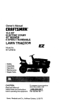
CRAFTSMAN
+
20.5 HP
ELECTRIC START
42" MOWER
AUTOMATIC
LAWN TRACTOR
Model No.
917.270840
•
•
•
•
Safety
Assembly
Operation
Maintenance
• Repair Parts
CAUTION:
Read and follow all
Safety Rules and Instructions
before operating this equipment.
For answers to your questioJ ;
about this product, Call:
1-800-659-5917
Sears Craftsman Help Line
5 am - 5 pm, Mon- Sat
Sears, Roebuck and Co., Hoffman Estates, IL 60179
Visit our Craftsman
website:
www.sears.com/craftsman
Warranty .................. ................... , ........... 2
Safety Rules ......................... ,, ............... 2
Product Specifications ...........................
5
Assembly ..................... ,...._ ......... _ .......... 8
Operation ............. ...................... _;......... 12
Maintenance Schedule.:...: ................... 19
LIMITED
TWO YEAR WARRANTY
M'aintenance .............................. i .......... 19
Service and Adjustments ........... _;......... 23
Storage ................................................. 29
Troubleshooting .................................... 31
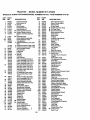
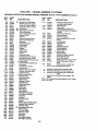
Repair Parts ....................................... .34
Parts Ordering ...................... :Back Cover
ON CRAFTSMAN
RIDING
EQUIPMENT
For two (2) years from the date of purchase, if this Craftsman Riding Equipment is maintained, lubricated and tuned up according to the instructions :in the owner's manual,
Sears wile repair or replace, free of charge, any parts found to be defective in material or
workmanship:
This Warranty does not cover:.
• Expendable items which become worn dudngnormal
use, such as blades, spark
plugs, air cleaners, belts, etc.
• "i3re replacement or repair caused by punctures from outside objects, such as nails,
thorns, stumps, or glass.
• Repairs necessary because of operator abuse, negligence, improper storage or accident or the failure to maintain the equipment according to the instructions contained in
the owner's manual.
• Riding equipment
LIMITED
used for commercial or rental purposes.
90 DAY WARRANTY
ON BATTERY
For ninety (90) days from date of purchase, if any battery included with this riding equipment proves defective in material or workmanship and our testing determines the battery will not hold a charge, Sears will replace the battery at no charge. In-home warranty
service on your Craftsman dding equipment is available at no charge for 30 days from
the date of purchase. Please contact your nearest service center. After 30 days from the
date of pumhase, warranty service is available by taking your Craftsman riding equipment to your nearest Sears Service Center. (In-home warranty service will still be available after 30 days from the date of purchase but a standard trip charge will apply). This
warranty applies only while this product is in the United States, This Warranty gives you
specific legal rights, and you may also have other rights which may vary from state to
state.
Sears, Roebuck and Col, D/817 WA, Hoffman Estates, IL 60179
GENERAL
OPERATION
• Read, understand, and follow all instructions in the manual and on the machine
before starting.
• Only allow responsible adults, who are
familiar with the instructions, to operate
the machine.
• Clear the area of objects such as rocks,
toys, wire, etc., which could be picked
up and thrown by the blade.
• Be sure the area is clear of other people
before mowing. Stop machine if anyone
enters the area.
• Never carry passengers.
• Do not mow in reverse unless absolutely necessary. Always look down and
behind before and while backing.
• Be aware of the mower discharge direction and do not point it at anyone. Do
not operate the mower without either
the entire grass catcher or the guard in
place.
• Slow down before tuming.
• Never leave a running machine unattended. Always turn off blades, set parking brake, stop engine, and remove
keys before dismounting.
• Turn off bladeswhen not mowing.
• Do nottry tb stabilize the machine by
putting your foot on the ground.
• Do not use grass catcher on steep
slopes.
• Stop engine before removing grass
catcher or unclogging chute.
• Mow only in daylight or good artificial
light.
• Do not operate the machine while under
the influence of alcohol or drugs.
• Watch for traffic when operating near or
crossing roadways.
• Use extra care when loading or unloading the machine into a trailer or truck.
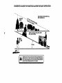
SLOPE
CHILDREN
Tragic accidents can occur if the operator
is not alert to the presence of children.
Children are often attracted to the
machine and the mowing activity. Never
assume that children will remain where
you last saw them.
• Keep children out of the mowing area
and under the watchful care of another
responsible aduit.
• Be alert and turn machine off if children
enter the area.
OPERATION
Slopes are a major factor related to lossof-control and tipover accidents, which
can result in severe injury or death. All
slopes require extra caution. If you cannot
back up the slope or if you feel uneasy on
it, do not mow it.
DO:
• Before and when backing, look behind
and down tor small children.
• Never carry children. They may fall off
and be seriously injured or interfere with
safe machine operation.
• Never allow children to operate the
machine.
• Mow up and down slopes, not across.
• Remove obstacles such as rocks, tree
limbs, etc.
• Watch for holes, ruts, or bumps. Uneven
terrain could overtum the machine. Tall
• Use extra care when approaching blind
comers, shrubs, trees, or other objects
that may obscure vision.
grass can hide obstacles.
• Use slow speed. Choose a low gear so
that you will not have to stop or shift
while on the slope.
• Follow the manufacturer's recommen-
SERVICE
• Use extra care in handling gasoline and
other fuels. They are flammable and
vapors are explosive.
Use only an approved cOntainer.
Never remove gas cap or add fuel
with the engine running. Allow engine to cool before refueling. Do not
smoke.
Never refuel the machine indoors.
Never store the machine or fuel
container inside where there is an
open flame, such as a water heater.
• Never run a machine inside a closed
area.
• Keep nuts and bolts, especially blade
attachment bolts, tight and keep equipment in good condition.
• Never tamper with safety devices.
Check their proper operation regularly.
• Keep machine free of grass, leaves, or
other debris build-up. Clean oil or fuel
spillage. Allow machine to cool before
storing.
• Stop and inspect the equipment if you
strike an object. Repair, if necessary,
before restarting.
dations for wheel weights or counterweights to improve stability.
• Use extra care with grass catchers or
other attachments. These can change
the stability of the machine.
• Keep all movement on the slopes slow
and gradual. Do not make sudden
changes in speed or direction.
• Avoid starting or stopping on a slope. If
tires lose traction, disengage the blades
and proceed slowly straight down the
slope.
DO NOT:
• Do not turn on slopes unless necessary,
and then, turn slowly and gradually
downhill, if possible.
• Do not mow near drop-offs, ditches, or
embankments. The mower could suddenly turn over if a wheel is over the
edge of a cliff or ditch, or if an edge
cavus in.
• Do not mow on wet grass. Reduced
traction could cause sliding.
3
• Never make adjustments or repairs with
the engine running.
• Grass catcher components are subject
to wear, damage, and detedoration,
which could expose moving parts or
allow objects to be thrown. Frequently
check components and replace with
manufacturer's recommended pads,
when necessary.
• Be sure the area is clear of other people
before mowing. Stop machine if anyone
enters the area.
• Never carry passengers.
• Do not mow in reverse unless absolutely necessary. Always look down and
behind before and while backing.
• Never carry children. They may fall off
and be seriously injured or interfere with
safe machine operation.
• Keep children out of the mowing area
and under the watchful care of another
responsible adult.
• Be alert and turn machine off if children
enter the area.
• Before and when backing, look behind
and down for small children.
_Look
for this symbol to point out important safety precautions. It means CAUTION!!! BECOME AWARE!!! YOUR SAFETY IS INVOLVED.
,_CAUTION:
In order to prevent accidental starting when setting up, transporting,
adjusting or making repairs always disconnect spark plug wire and place wire where
it cannot contact spark plug.
• Mower blades
and can cut.
Wrap the blade(s) or wear gloves, and
use extra caution when sewicing them.
• Check brake operation frequently.
Adjust and service as required.
• Mow up and down slopes (15 ° Max), not
across.
• Remove obstacles such as rocks, tree
limbs, etc.
• Watch for holes, ruts, or bumps. Uneven
terrain could overturn the machine. Tall
grass can hide obstacles.
• Use slow speed. Choose a low gear so
that you will not have to stop or shift
while on the slope.
• Avoid starting or stopping on a slope. If
tires lose traction, disengage the blades
and proceed slowly straight down the
slope.
• Do nottum on slopes unless necessary,
and then, turn slowly and gradually
downhill, if possible.
,_WARNING:
The engine exhaust from
this product contains chemicals known to
the State of California to cause cancer,
birth defects, or other: reproductive harm.
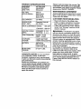
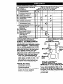
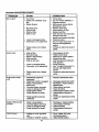
PRODUCT
SPECIFICATIONS
3ASOLINE
CAPACITY
AND TYPE:
3.5 GALLONS
UNLEADED
REGULAR
OIL TYPE
API-SF/SG/SH):
SAE 30
(above 32°F)
SAE 5W-30
Please read and retain this manual. 3_e
instructions will enable you to asseml_le
and maintain your tractor properly, Alway.,
observe the "SAFETY RULES".
MAINTENANCE
A Sears Maintenance Agreement is available on this product. Contact your neares
Sears store for details.
(below 32°F)
CUSTOMER
OIL CAPACITY:
3.0 PINTS
SPARK PLUG:
(GAP: .030")
Champion RJ19LM
OR J19LM
VALVE CLEARANCE:
GROUND
SPEED
AGREEMENT
INTAKE:
.005-.007
EXHAUS'E
.009-.011
RESPONSIBILITIES
• Read and observe the safety rules,
• Follow a regular schedule in maintaining, caring for and using your tractor,
• Follow the instructions under "Maintenance" and "Storage"
owner's manual.
sections of this
FORWARD:
0-5.5
_WARNING:
(MPH):
REVERSE:
0- 2.4
TIRE PRESSURE:
FRONT: 14 PSI
REAR: 10 PSI
CHARGING
;YSTEM:
3 AMPS BATTERY
5 AMPS HEADLIGHTS
with an internal combustion
engine and
should not be used on or near any unimproved forest-covered,
brush-covered
or
grass-covered land unless the engine's
exhaust system is equipped with a spark
arrester meeting applicable local or state
laws (if any). If a spark arrester is used, it
should be maintained in effective working
order by the operator.
In the state of California the above is
_ATFERY:
:,LADE BOLT
TORQUE:
AMP/HR:30
MIN. CCA:240
CASE SIZE: U1R
27-35 FT. LBS.
This tractor
is equipped
required by law (Section 4442 of the
California Public Resources Code). Other
states may have similar laws. Federal
laws apply on federal lands. A spark
arrester for the muffler is available throug
your nearest Sears Authorized Service
Center (See REPAIR PARTS section of
this manual).
CONGRATULATIONS
on your purchase
of a Craftsman Tractor. It has been
designed, engineered and manufactured
to give you the best possible dependability
and performance.
Should you experience any problem you
cannot easily remedy, please contact your
nearest Sears Authorized Service Center.
We have competent, well-trained technicians and the proper tools to service or
repair this tractor.
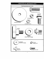
5
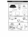
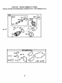
Parts Bag contents shown full size
/
f
\
\
\
\
(1) Hex Bolt 5116-18 x 1-1/4
©
3/8-16 x 1
(1) Hex BoAt
(1) Lockwasher 3/8
@
(1) Large Flat Washer
(1) Locknut 5/16-18
(1) Knob
i
(1) Shoulder
Bolt 5/16-18
(1) Washer
i7/32 x 1-3/16 x 12 Gauge
(2) Washers
3/16 x 3/4 x 16 Gauge
(2)
Weld
Nuts
#10
(2) Lock #10
Washers
_#10
x 5/8
Parts packed separately in carton
Steenng
Boot
Seat
Video
Cassette
Mulc-_er
Plate
!?
Manual
Steedng
Wheel
Parts Bag
Parts Bag contents not shown full size
_(2)
Center-
(2) Shoulder
Bolts
" lockNuts
(2) Washers 3/8
x 7/8 x 14 Gauge
Steedng Wheel Adapter
(2) Gauge
Wheels
_=J
Slope Sheet
7
Extension
Shaft
Steedng
Wheel Insert
(2) Keys _
(2) Latch Hook
Assemblies
t
Steedng
Your new tractor has been assembled at the factory with exception of those pads left
unassembled for shipping purposes. To ensure safe and proper operation of your tract_
all parts and hardware you assemble must be tightened securely. Use the correct tools
as necessary to insure proper tightness. Review the video cassette before you begin.
TOOLS REQUIRED FOR
ASSEMBLY
A socketwrenchset will make assembly
easier. Standard wrenchsizesyou need
are listed below.
(1) 3/4" Socket w/
drive rachet
(1) Phillips Screwdriver
(1) "fire pressure
gauge
(1) 9/16" wrench
(1) 3/4" wrench
(2) 1/2" wrench
(1) Utility knife
(1)Pliers
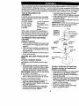
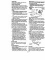
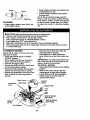
• Assemble large flat washer, 3/8 lock
washer, 3/8 hex bolt and tighten securel_
• Snap steering wheel insert into center
of steering wheel.
• Remove protective materials from tractor hood and grill.
IMPORTANT: Check for and remove any
staples in skid that may puncture tires
where tractor is to roll off skid.
Insert
When right or left hand is mentioned in
this manual, it means, from your point of
view, when you are in the operating position (seated behind the steering wheel).
TO REMOVE
TRACTOR
_
%_3/8
3/8 Hex
Bolt
Lockw_usher
_
._. <-_
7.
Large Rat
Washer
FROM
CARTON
UNPACK CARTON
• Remove all accessible
loose parts and
Wheel
parts boxes from shipping carton (See
page 6).
• Cut, from top to bottom, along lines on
all four corners of shipping carton, and
lay panels flat.
• Check for any additional loose parts or
boxes and remove.
Extension
Shaft
STEERING
ASSEMBLE
BOOT
_
_
5/16 Hex
B_t
f--_..,).
Lower Steering _
S.aft
WHEEL
EXTENSION
_!/dapter
5116 L(_knut_
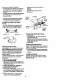
BEFORE ROLLING TRACTOR OFF
SKID
ATTACH
_Boot
._ "-""_"_-- -.
/--'I3'
;-..
o
""
/
;
SHAFT AND
• Slide extension shaft onto lower steer-
TO ROLL TRACTOR OFF SKID (See
Operation section for location and
function of controls)
• Press lift lever plunger and raise attach
merit lift lever to its highest position.
• Release parking brake by depressing
clutch/brake pedal
• Place freewheel control in freewheeling
position to disengage transmission
(Se,
=TO TRANSPORT"
in the Operation
section of this manual).
• Roll tractor forward off skid.
• Remove banding holding discharge
guard up against tractor.
ing shaft. Align mounting holes in extension and lower shafts and install 5/16
hex bolt and Iocknut. Tighten securely.
-IMPORTANT:
Tighten bolt and nut securely to 18-22 ft. Ibs. torque.
• Place tabs of steering boot over tab
slots in dash and push down to secure.
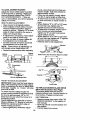
INSTALL STEERING WHEEL
• Position front wheels of the tractor so
they are pointing straight forward.
• Slide steering wheel adapter onto steering shaft extension.
• Position steering wheel so cross bars
are horizontal (left to right) and slide
inside boot and onto adapter.
8
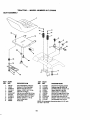
HOW TO SET UP YOUR TRACTOR
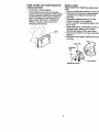
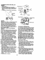
INSTALL
CHECK
Adjust seat before tightening adjustment
knob.
• Remove cardboard packing on seat p_
• Place seat on seat pan and assemble
shoulder bolt. "13ghten shoulder bolt
securely•
• Assemble adjustment
knob and flat
washer loosely. Do not tighten.
• Lower seat into operating position and
sit on seat.
• Slide seat until a comfortable
position
reached which allows you to press
clutch/brake
pedal all the way down.
• Get off seat without moving its adjuste
position.
• Raise seat and tighten adjustment kno
securely.
BATTERY
• Lift hood to raised position.
• If this battery is put into service after
month and year indicated on label (label
located between terminals) charge battery for minimum of one hour at 6-10
amps. (See "BATTERY" in MAINTENANCE section of this manual for
charging
instructions).
÷. _...
,"
o..
;
--Label
.*
""" -,t
tJ>"
SEAT
Seat
I
Seat Pan
Shoulder
B_t
Flat Washer
Adjustment Knob
9
i
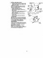
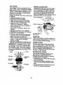
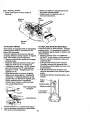
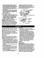
INSTALL MULCHER
PLATE
, • install two latch hooks to mulcher plate
•
using screw, washer, lock washer, and
weld nut as shown.
NOTE: Pre-assemble weld nut to latch
hook by inserting weld nut from the top
with hook pointing down.
• _ghten hardware securely.
• Raise and hold deflector shield in upright position.
• Place front of mulcher plate over front of
mower deck opening and slide into
place, as shown.
• Hook front latch into hole on front of
mower deck.
• Hook rear latch into hole on back of
mower deck.
_CAUTION:
Do not remove discharge
Weld Nut From
The Top
Weld
Hook Points
Down
Lock
Washer
Latch
Latch
Hook
Washer
Lock Washer
Washer
Mulcher
Plate
Deflector
Shield
_i"
"_-
Screw
_,_
_'_
guard from mower. Raise and hold guard
- when attaching mulcher plate and allow it
to rest on plate while in operation.
TO CONVERT TO BAGGING OR
DISCHARGING
Simply remove mulcher plate and store in
a safe place. Your mower is now ready for
discharging or installation of optional
grass catcher accessory.
NOTE: It is not necessary to change
blades. The mulcher blades are designed
for discharging and bagging also.
Latch
Hooks
10
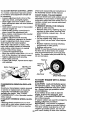
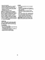
ASSEMBLE
GAUGE
WHEELS
TO
CHECK
MOWqR DECK
The gauge wheels are designed to keep
the mower deck in proper position when
operating mower. Be sure they are p_perly adjusted to ensure optimum mower performance.
Gauge Wheel
Bracket \
SYSTEM
After you learn how to operate your tractor, check to see that the brake is preperl 1
adjusted. See "TO ADJUST BRAKE" in
the Service and Adjustments section of
this manual.
• Assemble gauge wheels with tractor on
a flat level surface.
• Adjust mower to desired cutting height
(See "TO ADJUST MOWER CUTTING
HEIGHT" in the Operation section of
this manual).
• With mower in desired height of cut position, gauge wheels should be assembled so they are slightly off the ground.
Install gauge wheel in appropriate hole
with shoulder bolt, 3/8 washer, and 3/816 Iocknut and tighten securely.
• Repe_at for opposite side installing
gauge wheel in same adjustment hole.
BRAKE
v"CHECKLIST
PLEASE REVIEW THE FOLLOWING
CHECKLIST:
v' All assembly
completed.
instructions
have been
No remaining loose parts in carton.
v' Battery is properly prepared and
charged.
(Minimum 1 hour at 6 amps).
V' Seat is adjusted comfortably
and
tightened securely.
_' AU tires are propedy inflated. (For
shipping purposes, the tires wereoverinflated at the factory).
v' Be sure mower deck is properly levele_
side-to-side/front-to-rear
for best
-.
cutting results. (Tires must be properly
inflated for leveling).
v' Check mower and drive belts. Be sure
Bolt
3/8-16 Washer
e Wheel
CHECK
TIRE PRESSURE
The tires on your tractor were overinflated
at the factory for shipping purposes.
Correct tire pressure is important for best
cutting performance.
• Reduce tire pressure to PSI shown in
=PRODUCT SPECIFICATIONS"
on
they are routed properly around pulley:
and inside all belt keepers.
v' Check wiring. See that all connections
are still secure and wires are properly
clamped.
Before driving tractor, be sure freewheel control is in drive position.
WHILE LEARNING HOWTO
USE YOUR
TRACTOR, PAY EXTRA ATTENTION TO
THE FOLLOWING
IMPORTANT
ITEMS:
4" Engine oil is at proper level.
4' Fuel tank is filled with fresh, clean,
regular unleaded gasoline.
•/ Become familiar with all controls - their
page 5 of this manual.
CHECK
DECK
LEVELNESS
For best cutting results, mower housing
should be properly leveled. See "TO
LEVEL MOWER HOUSING" in the
/
/
Service and Adjustments section of this
manual.
CHECK FOR PROPER
ALL BELTS
POSITION
OF
See the figures that are shown for replacing motion and mower blade drive belts in
the Service and Adjustments sectoin of
this manual. Verify that the belts are routed correctly.
11
location and function. Operate them
before you start the engine.
Be sure brake system is in safe operat
ing condition.
It is important to purge the transmission before operating your tractor for
the first time. Follow proper starting
and transmission
purging instructions
(See "TO START ENGINE" and
"PURGE TRANSMISSION"
in the Op
eration section of this manual).
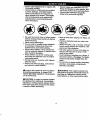
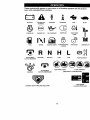
These symbols m_y appear on your tractor or in literature supplied with the product.
Learn and understand their meaning.
BATTERY
CAUTION OR
WARNING
REVERSE
ENGINE ON
ENGINE OFF
OIL PRESSURE
FORWARD
FAST
SLOW
LIGHTS ON
LIGHT
®
FUEL
CHOKE
MOWER HEIGHT
PARKING BRAKE
LOCKED
OVER TEMP
UNLOCKED
Ijim
MOWER LIFT
R N H L
ATTACHMENT
CLUTCH ENGAGED
REVERSE
NEUTRAL
ATTACHMENT
IGNITION
CLUTCH DISENGAGED
HIGH
LOW
PARKING BRAKE
KEEP AREA CLEAR
SLOPE HAZARDS
(SEE SAFETY RULES SECTION)
FREE WHEEL
DANGER, KEEP HANDS AND FEET AWAY
(Automatic Models only)
12
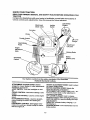
I
KNOW YOUR TRACTOR
READTHISOWNER'SMANUALAND SAFETYRULESBEFOREOPERATINGYOU_
TRACTOR
Compare the illustrations with your tractor to familiarize yourself with the locations
various controls and adjustments. Save this manual for future reference.
Attachment
Clutch Lever
Ignition
Switch
of
Ught Switch
Position
Ammeter
Choke
Throttle _ntrol"_
Lift Lever
Plunger
Clutch/Brake
Pedal
Attachment
Lift Lever
Height
Knob
Parking Brake
Motion
Control Lever
Freewheel
Control
Our tractors conform to the safety standards of the American
National Standards Institute.
ATTACHMENT CLUTCH LEVER: Used to
engage the mower blades, or other attachments
mounted to your tractor.
LIGHT SWITCH: Turns the headlights on and
off.
CHOKE CONTROL: Used when starting a cold
engine.
THRO'FrLE CONTROL: Used to control engine
speed.
CLUTCH/BRAKE PEDAL: Used for declutching and braking the tractor and starting the
engine.
FREEWHEEL CONTROL: Disengages transmission for pushing or slowly towing the tractor
with the engine off.
HEIGHT ADJUSTMENT KNOB: Used to adjust
the mower cutting height.
MOTION CONTROL LEVER: Selects the
speed and direction of the tractor.
ATTACHMENT LIFT LEVER: Used to rai_;_ ant
lower the mower deck or other attachments
mounted to your tractor.
LIFT LEVER PLUNGER: Used to release
attachment liR lever when changing its position.
IGNITION SWITCH: Used for starting and stopping the engine.
AMMETER: Indicates battery charging (+) or
discharging (-).
PARKING BRAKE: Locks clutch/brake into the
brake position.
13
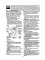
The operationof any tractorcan resultin foreignobjectsthrownintothe
eyes,whichcan resultin severeeye damage.Alwayswearsafetyglasses
or eye shieldswhileoperatingyour tractoror performingany adjustmentsor
repairs.We recommenda wide vision safetymaskoverspectacles,or standardsafetyglasses.
HOW TO USE YOUR TRACTOR
Your tractor is equipped with an operator
presence sensing switch. When engine is
running, any attempt by the operator to
leave the seat without first setting the
parking brake will shut off the engine.
TO SET PARKING
BRAKE
• Depress clutch/brake pedal into full
=BRAKE" position and hold.
• Place parking brake lever in =ENGAGED" position and release pressure
from clutch/brake pedal. Pedal should
remain in =BRAKE" position. Make sure
parking brake will hold tractor secure.
Attachment Clutch
Choke
Control
Lever =Engaged"
Position
=Disengaged"
Control
Parking Brake
=Brake"
Position
Pedal =Drive"
Position
"Diser_gaged"
Position
Motion
Control
Lever
STOPPING
MOWER BLADES • To stop mower blades, move attachment clutch lever to =DISENGAGED"
position.
GROUND DRIVE• To stop ground drive, depress
clutch/brake pedal into full =BRAKE"
position.
• Move motion control lever to neutral (N)
position.
IMPORTANT: The motion control lever
does not retum to neutral (N) position
when the clutch/brake pedal is depressed.
ENGINE • Move throttle control to slow position.
NOTE: Failure to move throttle control to
slow position and allowing engine to idle
before stopping may cause engine to
Ubackfire".
• Turn ignition key to "OFF" position and
remove key. Always remove key when
leaving tractor to prevent unauthorized
use.
• Never use choke to stop engine.
IMPORTANT:
Leaving the ignition switch
in any position other than "OFF" will cause
the battery to be discharged, (dead).
NOTE: Under certain conditions when
tractor is standing idle with the engine running, hot engine exhaust gases may
cause Ubrewning" of grass. To eliminate
this possibility, always stop engine when
stopping tractor on grass areas.
CAUTION:
Always stop tractor com-
pletely, as described above, before leaving
the operator's position; to empty grass
catcher, etc:
THROTTLE
CONTROL
Always operate engine at full throttle.
• Operating engine at less than full throttle reduces the battery charging rate.
• Full throttle offers the best bagging and
mower performance.
CHOKE CONTROL
Use choke control whenever you are starting a cold engine. Do not use to start a
warm engine.
• To engage choke control, pull knob out.
Slowly push knob in to disengage,
TO MOVE FORWARD AND BACKWARD
The direction and speed of movement is
controlled by the motion control lever.
• Start tractor with motion control lever in
neutral (N) position.
• Release parking brake and clutch/brake
• pedal.
• Slowly move motion control lever to
desired position.
NOTE: The effort to move the motion control lever will reduce after the first few
hours of use. This is normal.
TO ADJUST
MOWER
CU'I'rlNG
HEIGHT
The cutting height is controlled by tuming
the height adjustment knob in desired
14 direction.
• Turn knob clockwise (G) to raise cutting
height.
• Turn knob counterclockwise (,b)to
lower cutting height.
The cutting height range is approximately
1-1/2" to 4". The heights are measured
from the ground to the blade tip with the
engine not running. These heights are approximate and may vary depending upon
soil conditions, height of grass andtypes
of grass being mowed.
• The average lawn should be cut to
approximately
2-1/2 inches during the
cool season and to over 3 inches during
hot months. For healthier and better
looking lawns, mow often and after
moderate growth.
• For best cutting performance,
grass
over 6 inches in height should be
mowed twice. Make the first cut relatively high; the second to desired
TO OPERATE MOWER
height.
Your tractor is equipped with an operator
presence sensing switch. Any attempt by
the operator to leave the seat with the
engine running and the attachment clutch
engaged will shut oft the engine.
• Select desired height of cut.
• Lower mower with attachment
lift control.
• Start mower blades by engaging attachment clutch control.
• TO STOP MOWER BLADES ; disengage attachment
Attachment Clutch
Lever "Engaged"
Position
clutch control.
• If slowing is necessary, move throttle
control lever;to slower position.
• If stopping islabsolutely necessary, push
clutch/brake pedal quickly to brake position and engage parking brake.
• Move motion control lever to neutral (N)
position.
IMPORTANT: "rhe motion control lever
does not return to neutral (N) position
when the clutch/brake pedal is depressed.
• To restart movement, slowly release
parking brake and clutch/brake pedal.
• Slowly move motion control lever to
slowest setting.
• Make all turns slowly.
TO TRANSPORT
When pushing or towing your tractor, be
sure to disengage transmission by placing
freewheel control in freewheeling
position.
Freewheel control is located at the rear
drawbar of tractor.
• Raise attachment lift to highest position
with attachment lift control.
• Pull freewheel control knob out and hold
in position by inserting retainer spring
into forward hole of contro_ rod.
• Do not push or tow tractor at more than
two (2) MPH.
• To reengage transmission, reverse
above procedure.
NOTE: To protect hood from damage when
transporting your tractor on a truck or a
trailer, be sure hood is closed and secured
to tractor. Use an appropriate means of
tying hood to tractor (rope, cord, etc.).
Attachment Lift
Lever High Position
"Disengaged"
;"
Low
Position
TOWING CARTS AND OTHER
ATTACHMENTS
TO OPERATE
ON HILLS
_,CAUTION:
Do not drive up or down
hills with slopes greater than 15 ° and do
not drive across any slope. Use the slope
guide provided at the back of this manual.
• ChoG._ the slowest speed before starting up or down hills.
• Avoid stopping or changing speed on
hills.
Tow only the attachments that are recommendedby and comply with specifications
of the manufacturer
of your tractor. Use
common sense when towing. Too heavy of
a load, while on a slope, is dangerous.
Tires can lose traction with the ground and
cause you to lose control of your tractm.
15
BEFORE STARTING THE ENGINE
CHECK
ENGINE
OIL LEVEL
shipped, from the factory, already filled
The engine
with
summer inweight
your tractor
oil.
has been
Check engine oil with tractor on level
ground.
• Remove oil fill cap/dipstick and wipe
clean, reinsert the dipstick and screw
cap tight, wait for a few seconds,
remove and read oil level. If necessary,
add oil until =FULL" mark on dipstick is
reached. Do not overfill.
i
• For cold weather operation you should
change oil for easier starting (See =OIL
VISCOSITY
CHART" in the Maintenance section of this manual).
• To change engine oil, see the Maintenance section in this manual.
ADD
• Be sure freewheel control is in the
transmission engaged position.
• Sit on seat in operating p6sition,
depress clutch/brake pedal and set
parking brake.
• Place motion control lever in neutral (N)
position.
• Move attachment clutch to =DISENGAGED" position.
• Move throttle control to fast position
• Pull choke control out for a cold engine
start attempt. For a warm engine start
attempt the choke control may not be
needed.
NOTE: Before starting, read the warm and
cold starting procedures below.
• Insert key into ignition and turn key
clockwise to =START" position and
release key as soon as engine starts.
Do not run starter Continuously for more
than fifteen seconds per minute. If the
engine does not start after several
attempts, push choke control in, wait a
few minutes and try again. If engine still
does not start, pull the choke control out
and retry.
GASOLINE
• Fill fuel tank. Use fresh, clean, regular
unleaded gasoline with a minimum of 87
octane. (Use of leaded gasoline will
increase carbon and lead oxide
deposits and reduce valve life). Do not
mix oil with gasoline. Purchase fuel in
quantities that can be used within 30
days to assure fuel freshness.
IMPORTANT:
When operating in temperatures below 32°F(0°C), use fresh, clean
winter grade gasoline to help insure good
_Nweather
starting.
ARNING: Experience indicates that
alcohol blended fuels (called gasohol or
using ethanol or methanol) can attract
moisture which leads to separation and
formation of acids during storage. Acidic
gas can damage the fuel system of an
engine while in storage. To avoid engine
problems, the fuel system should be emptied before storage of 30 days or longer.
Drain the gas tank, start the engine and let
it run until the fuel lines and carburetor are
empty. Use fresh fuel next season. See
Storage Instructions for additional information. Never use engine or carburetor
cleaner products in the fuel tank or permaznt damage may occur.
CAUTION: Fill to bottom of gas tank
filler neck. Do not overfill. Wipe off any
spilled oil or fuel. Do not store, spill or use
gasoline near an open flame.
TO START ENGINE
When starting the engine for the first time
or if the engine has run out of fuel, it will
take extra cranking time to move fuel from
the tank to the engine.
WARM WEATHER
AND ABOVE)
STARTING
(50 ° F
• When engine starts, slowly push choke
control in until the engine begins to run
smoothly. If the engine starts to run
roughly, pull the choke control out slightly for a few seconds and then continue
to push the control in slowly.
• The attachments and ground drive can
now be used. If the engine does not
accept the load, restart the engine and
allow it to warm up for one minute using
the choke as described above.
COLD WEATHER STARTING (50 ° F AND
BELOW)
• When engine starts, slowly push choke
control in until the engine begins to run
smoothly. Continue to push the choke
control in small steps allowing the
engine to accept small changes in
speed and load, until the choke control
is fully in, If the engine starts to run
roughly, pull the choke control out slightly for a few seconds and then continue
to push the control in slowly. This may
require an engine warm-up period from
several seconds to several minutes,
depending on the temperature.
16
AUTOMATICTRANSMISSION
WARM-UP
NOTE: Dudng this procedure there will b,
no movement of drive whee s. TheJair is
being removed from hydraulic ddv6 system.
• Move motion control lever to neutral (N
position. Shut off engine and set parkin
brake.
• Engage transmission by placing freewheel control in driving position (See
"TO TRANSPORT" in this section of
manual).
• Sitting in the tractor seat, start engine.
After the engine is running, move throttie control to half (1/2) speed. With
motion control lever in neutral (N) posi
tion, slowly disengage clutch/brake
pedal.
• Slowly move motion control lever forward; after the tractor moves approximately five (5) feet, slowly move motio=
control lever to reverse position..After
the tractor moves approximately five (5
feet return the motion control lever to
the neutral (N) position. Repeat this pn
cedure with the motion control lever
three (3) times.
• Your tractor is now purged and ready fc
normal operation.
MOWING TIPS
• Tire chains cannot be used when the
mower housing is attached to tractor.
• Mower should be propedy leveled for
best mowing performance. See "TO
LEVEL MOWER HOUSING" in the
Service and Adjustments section of thi:
manual.
• The left hand side of mower should be
used for trimming.
• Drive so that clippings are discharged
onto the area that has been cut. Have
the cut area to the rightof the tractor.
This will result in a more even distribution of clippings and more uniform cutting.
• When mowing large areas, start t_ytur,
ing to the right so that clippings will dir
charge away from shrubs, fences, dri_
ways, etc. After one or two rounds, mo_
in the opposite direction making left
hand turns until finished.
• If grass is extremely tall, it should be
mowed twice to reduce load and possible fire hazard from dried clippings.
Make first cut relatively high; the secon
to the desired height.
• Before driving the unit in cold weather,
the transmission
should be warmed up
as follows:
• Be sure the tractor is on level ground.
• Place the motion control lever in neutral. Release the parking brake and
let the clutch/brake slowly retum to
operating position.
• Allow one minute for transmission to
warm up. This can be done during the
engine warm up period.
• The attachments can be used during
the engine warm-up period after the
transmission has been warmed up and
may require the choke control be pulled
out slightly.
NOTE: A high altitude (above 3000 feet)
or in cold temperatures (below 32 F) the
carburetor fuel mixture may need to be
adjusted for best engine performance.
See "TO ADJUST CARBURETOR" in the
Service and Adjustments section of this
manual.
,_RGE
TRANSMISSION
CAUTION: Never engage or disengage freewheel lever while the engine is
running.
To ensure proper operation and performance, it is recommended that the transmission be purged before operating tractor
for the first time. This procedure will
remove any trapped air inside the transmission which may have developed during
shipping of your tractor.
IMPORTANT:
Should your transmission
require removal for service or replacement, it should be purged after reinstallation before operating the tractor.
• Place tractor safely on level surface with
engine off and parking brake set.
• Disengage transmission by placing freewheel control in freewheeling position
(See "TO TRANSPORT"
in this section
of manual).
• Sitting in the tractor seat, start engine.
After the engine is running, move throttle control to slow position. With motion
control lever in neutral (N) position,
slowly disengage clutch/brake pedal.
• Move motion control lever to full forward
position and hold for five (5) seconds.
Move lever to full reverse position and
hold for five (5) seconds. Repeat this
procedure three (3) times.
17
• Do not mow grass when it is wet. Wet
grass will plug mower and leave undesirable clumps. Allow grass to dry
before mowing.
• Always operate engine at full throttle
when mowing to assure better mowing
performance and proper discharge of
material. Regulate ground speed by selecting a low enough gear to give the
mower the best cutting performance as
well as the quality of cut desired.
• When operating attachments,
select a
ground speed that will suit the terrain
and give best performance of the attachment being used.
f
1
/
MULCHING
MOWING TIPS
IMPORTANT: For best performance, keep
mower housing free of built-up grass and
trash. Clean after each use.
• The special mulching blade will recut
the grass clippings many times and
reduce them in size so that as they fall
onto the lawn they will disperse into the
grass and not be noticed. Also, the
mulched grass will biodegrade quickly
to provide nutrients for the lawn. Always
mulch with your highest engine (blade)
speed as this will provide the best recutting action of the blades.
• Avoid cutting your lawn when it is wet.
Wet grass tends to form clumps and
interferes with the mulching action. The
best time to mow your lawn is the early
afternoon. At this time the grass has
dried and the newly cut area will not be
exposed to the direct sun.
• For best results, adjust the mower cutting height so that the mower cuts off
only the top one-third of the grass
blades. For extremely heavy mulching,
reduce your width of cut on each pass
and mow slowly.
• Certain types of grass and grass conditions may require that an area be
mulched a second time to completely
hide the clippings. When doing a second cut, mow across or perpendicular to
the first cut path.
• Change your cutting pattem from week
to week. Mow north to south one week
then change to east to west the next
week. This will help prevent matting and
graining of the lawn.
18
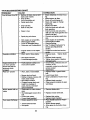
CUSTOMER
RESPONSIBILITIES
MAINTENANCE
SCHEDULE
__
._,_/_o_/'_'_'_y
AS YOU COMPLETE
_u'/._/,_/,_/._/._'_.___'f_R-_._'q_._OR_
REGULAR
d_,."_
SERVICE
_"_/_"_/_'_/"_''_'_"_f'_
SERVICE
DATES
Check Tire Pressure
T
R
Check Operator Presence and
Interlock Systems
I_
Check
_
for Loose
Fasteners
T
Lubrication Chart
A
0
Check Battery Level
Sharpen/Replace
Mower Blades
Clean Battery and Terminals
R
_7
If
_4
14 /
Check Transaxle Cooling
Adjust
Blade
Belt(s)
Tensiorl
V's
Adjust Motion Drive Belt(s) Tension
Check Engine Oil Level
l_s
I_
I_
Change Engine Oil
_R,a
E
N
Claan Air Filter
claan Air Screen
_,:
GI
Inspect Muffler/Spark Arrester
Replace
N
V'
I_
Oil Filter (If equipped)
_,2
Clean Engine Cooling Fins
I_=
Replace
Spark
If
Replace
Air Filter Paper
Plug
i/,
Cartridge
Replace Fuel Filter
V'
1 .Ghengemoreoftenwhenoperatlngunderaheavyloadorlnhlghambientten_oem_.
5.1fequlppedwithadjusta/b_system.
2. Sen4ce mo_eoften when operaUng in dlrW or dusty _.
6. Not m<MnKI Ifequipped wlth malntenanc_4me bette
7. Tlghten front rodeidvot bolt to 35 ft.-Ibs, rnmdmun_
0o not overUghte_.
3 - If equipped WiU1 oll filter, cltenge oil evet_" SO hO_ll.
4. RelY.ace blade_ more ollen v_mn mowing kl I_dy
Io_.
GENERAL
RECOMMENDATIONS
The warranty on this tractor does not cover
items that have been subjected to operator
abuse or negligence. To receive full value
from the warranty, operator must maintain
tractor as instructed in this manual. Some
adjustments will need to be made periodically to properly maintain your tractor.
All adjustments in the Service and
Adjustments section of this manual should
be checked at least once each season.
• Once a year you should replace the
spark plug, clean or replace air filter, and
check blades and belts for wear. A new
spark plug and clean air filter assure
proper air-fuel mixture and help your
engine run better and last longer.
BEFORE
•
•
•
•
EACH USE
Check engine oil level.
Check brake operation.
Check tire pressure.
Chec" operator presence and interlock
systems for proper operation.
• Check for loose fasteners.
LUBRICATION CHART
@
Zerk
Q Front Wheel
Zerk
Wheel
Bearing
Zerk
Engine
@
Clutch.
Pivot(s)
SAE 30 or 10w30 Motor OIL
General Purpose Grease
O Refer to Maintenance "Engine" Section
IMPORTANT:
Do not oil or grease the pivot
points which have special nylon bear-ings.
Viscous lubricants will attract dust and dirt
that will shorten the life of the self-!ubflca*.ing
bearings. If you feel they must be lubri,.:ated,
use only a dry, powdered graphite typ. • I,Jf)ricant sparingly.
19
TRACTOR
Alwaysobservesafetyruleswhenperformingany maintenance.
BRAKE OPERATION
If_tractorrequiresmorethan six (6) feet
stoppingdistanceat high speedin highest
gear,then brakemustbe adjusted.(See
"TO ADJUST
Adjustments
BRAKE" in the Service and
section of this manual).
TIRES
• Maintain proper air pressure in all tires
(See "PRODUCT SPECIFICATIONS"
on page 3 of this manual).
• Keep tires free of gasoline, oil, or insect
control chemicals which can harm rubber.
• Avoid stumps, stones, deep ruts, sharp
objects and other hazards that may
cause tire damage.
IMPORTANT:
To ensure proper assembly,
center hole in blade must align with star
on mandrel assembly.
Reassemble
hex bolt, lock washer and
flat washer in exact order as shown.
• Tighten bolt securely (27-35 Ft. Lbs,
torque).
IMPORTANT:
Blade bolt is grade 8 heat
treated.
Mandrel
Trailing
Assembly
Edge t
Blade Center
Hole
Flat Washer
Lock
Washer'_
Hex Bolt (Grade 8)*
TO SHARPEN BLADE
NOTE: We do not recommend sharpeningblade
but if you do, be sure the blade
isbaianced.
NOTE: To seal tire punctures and prevent
flat tires due to slow leaks, tire sealant
may be purchased from your local parts
dealer. Tire sealant also prevents tire dry
rot and corrosion.
OPERATOR
PRESENCE
Care should be taken to keep the blade
balanced. An unbalanced blade will cause
excessive vibration and eventual damage
to mower and engine.
• The blade can be sharpened with a file
or on a grinding wheel. Do not attempt
to sharpen while it is on the mower.
• To check blade balance, you will need a
5/8" diameter steel bolt, pin, or a cone
balancer. (When using a cone baiancer,
follow the instructions supplied with bal°
ancer).
NOTE: Do not use a nail for balancing
blade. The lobes of the center hole may
appear to be centered, but are not.
• Slide blade onto an unthreaded portion
of the steel bolt or pin and hold the bolt
or pin parallel with the ground. If blade
is balanced, it should remain in a horizontal position. If either end of the blade
moves downward, sharpen the heavy
end until the blade is balanced.
SYSTEM
Be sure that operator presence and interlock systems are working properly. If your
tractor does not function as described
below, repair the problem immediately.
• The engine should not start unless the
clutch/brake pedal is fully depressed
and attachment clutch control is in the
disengaged position.
• When the engine is running, any
attempt by the operator to leave the
seat without first setting the parking
brake should shut off the engine.
• When the engine is running and the
attachment clutch is engaged, any
attempt by the operator to leave the
seat should shut off the engine.
• The attachment clutch should never
operate unless the operator is in the
seat.
BLADE
Star
Center Hole
CARE
Blade
For best results mower blades must be
kept sharp.
blades.
Replace
5/8" Bolt
or Pin
bent or damaged
BLADE REMOVAL
• Raise mower to highest position to allow
access to blades.
• Remove hex bolt, lock washer and flat
washer securing blade.
• Install new or resharpened blade with
trailing edge up towards deck as shown.
BATTERY
Your tractor has a battery charging system
which is sufficient for normal use.
However, periodic charging of the battery
with an automotive charger will extend its
life.
20
• Keep battery and terminals clean.
• Keep battery bolts tight.
• Keep small vent holes open.
• Recharge at 6-10 amperes for 1 hour.
TO CLEAN BATI'ERY AND TERMINALS
Corrosion and dirt on the battery and terminals can cause the battery to =leak"
power.
• Remove terminal guard.
• Disconnect BLACK battery cable first
then RED battery cable and remove
battery from tractor.
• Rinse the battery with plain water and
dry.
• Clean terminals and battery cable ends
with wire brush until bright.
• Coat terminals with grease or petroleum
jelly.
• Reinstall battery (See =REPLACING
BATTERY" in the SERVICE AND
ADJUSTMENTS
section of this manual).
V-BELTS
Check V-belts for deterioration and wear
after 100 hours of operation and replace if
necessary. The belts are not adjustable.
Replace belts if they begin to slip from
wear.
TRANSAXLE
COOLING
The transmission fan and cooling fins
should be kept clean to assure proper
cooling.
Do not attempt to clean fan or transmission while engine is running or while the
transmission is hot.
• Inspect cooling fan to be sure fan
blades are intact and clean.
• Inspect cooling fins for dirt, grass clip
pings and other materials. To prevent
damage to seals, do not use compressed air or high pressure sprayer to
clean cooling fins.
TRANSAXLE
PUMP FLUID
ENGINE
LUBRICATION
Only use high quality detergent oil rated
with API service classification SF, SG or
SH. Select the oil's SAE viscosity grade
according to your expected operating tem
perature.
NOTE: Although multi-viscosity oils
(5W30, 10W30 etc.) improve starting in
cold weather, these muki-viscosity
oils wil!
result in increased oil consumption when
used above 32°1. Check your engine oil
level more frequently to avoid possible
engine damage from running low on oil.
Change the oil after every 25 hours of
operation or at least once a year if the
tractor is not used for 25 hours tn one
year.
Check the crankcase oil level before starting the engine and after each eight (8)
hours of operation. Tighten oil fill cap/dipstick securely each time you check the oil
level.
TO CHANGE
ENGINE
OIL
Determine temperature range expected
before oil change. All oil must meet API
service class'itication SF, SG or SH.
• Be suretractor is on level surface.
• Oil will drain more freely when warm.
• Catch oil in a suitable container.
• Remove oil fill cap/dipstick.
Be careful
not to allow dirt to enter the engine
when changing oil.
• Remove drain plug.
• After oil has drained completely, replac_
oil drain plug and tighten securely.
• Refill engine with oil through oil fill dipstick tube. Pour slowly. Do not overfill.
For approximate capacity see =PRODUCT SPECIFICATIONS"
on page 3 of
this manual.
• Use gauge on oil fill cap/dipstick for
checking level. Be sure dipstick cap is
tightened securely for accurate reading.
Keep oil at =FULL" line on dipstick.
o,
Air Screei_
Plug
The transaxle was sealed at the factory
and fluid maintenance is not required for
the life of the transaxle. Should the
transaxle ever leak or require servicing,
contact your nearest authorized service
center.
O,, Fill Cap/D,pstickt _ __
'
CLEAN
AIR SCREEN
Air screen must be kept free of dirt and
chaff to prevent engine damage from overheating. Clean with a wire brush or compressed air to remove dirt and stubborn
21dded gum fibers.
AIR FILTER
Your engine will not run properly using 8
dirty air filter. Clean the foam pre-cleaner
after every 25 hours of operation or every
season. Service paper cartridge every
100 hours of operation or every season,
whichever occurs first.
Service air cleaner more often under dusty
conditions.
• Remove knob(s) and cover.
TO SERVICE PRE-CLEANER
• Slide foam pre-cleaner off cartridge.
• Wash it in liquid detergent and water.
• Squeeze it dry in a clean cloth.
• Saturate it in engine oil. Wrap it in
clean, absorbent cloth and squeeze to
remove excess oil.
• if very dirtyor damaged, replace precleaner.
• Reinstall pre-cleaner over cartridge.
• Reinstall cover and secure with knob(s).
TO SERVICE CARTRIDGE
• Remove wing nuts and cartridge plate.
• Carefully remove cartridge to prevent
debris from entering carburetor.
• Clean cartridge by tapping gently on flat
surface. If very dirty or damaged,
replace cartridge.
• Reinstall cartridge plate, wing nuts, precleaner, cover and secure with knob(s),
IMPORTANT: Petroleum solvents, such
as kerosene, are not to be used to clean
the cartridge. They may cause deterioration of the cartridge. Do not oil cartridge.
Do not use pressurized air to clean or dry
cartridge.
ENGINE COOLING RNS
Remove any dust, dirt or oil from engine
cooling fins to prevent engine damage
from overheating. Air guJdecovers must
be removed. Remove side panels and
hood (See "TO REMOVE HOOD AND
GRILL ASSEMBLY" in the Service and Adjustments section of this manual).
Top Air Guide_
Engine Cooling
Air Guide Cover •
(Both Sides)
MUFFLER
Inspect and replace corroded muffler and
spark attester (if equipped) as it could create a fire hazard and/or damage.
SPARK PLUGS
Replace spark plugs at the beginning of
each mowing season or after every 100
hours Of operation, whichever occurs first.
Spark plug type and gap setting are
shown in =PRODUCT SPECIFICATIONS"
on page 5 of this manual.
IN-LINE
Knob
FUEL RLTER
The fuel filter should be replaced once
each season. If fuel filter becomes
clogged, obstructingfuel flow to carburetor, replacement is required.
• With engine cool, remove filter and plug
fuel line sections.
• Place new fuel filter in position in fuel
line with arrow pointing towards carburetor.
• Be sure there are no fuel line leaks and
clamps are properly positioned.
Wing Nut
Plate
Foam PreCleaner
Air Screen
22
Clamp
Clamp
Fuel Filter
CLEANING
• Clean engine, battery, seat, finish, etc.
of all foreign matter.
• Keep finished surfaces and wheels free
of all gasoline, oil, etc.
• Protect painted surfaces with automotive type wax.
We do not recommend using a garden
hose to clean your tractor unless the electrical system, muffler, air filter and carburetor are covered to keep water out. Water
in engine can result in a shortened engine
life.
_,CAUTION:
Before performing any service or adjustments:
• Depress clutch/brake pedal fully and set parking brake.
• Place motion control lever in neutral (N) position.
• Place attachment clutch in =DISENGAGED" position.
• Tum ignition key "OFF" and remove key.
• Make sure the blades and all moving parts have completely stopped.
• Disconnect spark plug wire from spark plug and place wire where it cannot come
in contact with plug.
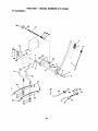
TO REMOVE MOWER
Mower will be easier to remove from the
right side of tractor.
• Place attachment clutch in "DISENGAGED" position.
• Move attachment lift lever forward to
lower mower to its lowest position.
• Roll belt off engine pulley.
• Disconnect clutch red from clutch lever
by removing retainer spring.
• Disconnect anti-swaybar from chassis
bracket by removing retainer spring.
• Disconnect suspension arms from rear
deck brackets by removing retainer
springs.
• Disconnect front links from deck by
removing retainer springs.
• Raise lift lever to raise suspension
arms. Slide mower out from under tractor.
IMPORTANT: If an attachment other than
the mower deck is to be mounted on the
tractor, remove the front links.
TO INSTALL MOWER
• Raise attachment lift leverto its highest
position.
• Slide mower under tractor with discharge guard to right side of tractor.
• Lower lift lever to its lowest position.
• Install mower in reverse order of
removal instructions.
Retainer
Suspe_on
Arms
Engine Pulley
• Front
Link
;pdngs
(BothSides)
;pdngs
(Both Sides)
Retainer
Spring
AntJ-Swaybar
23
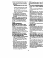
TO LEVELMOWERHOUSING
Adjustthe mowerwhile tractoris parked
on levelgroundor driveway. Make sure
tires are properlyinflated(See "PRODUCT SPECIFICATIONS').
If tiros are
over or underinflated, you will not propedy
adjust your mower.
SIDE-TO-SIDE ADJUSTMENT
• Raise mower to its highest position.
• At the midpoint of both sides of mower,
measure height from bottom edge of
mower to ground. Distance "A" on both
sides of mower should be the same or
within 1/4" of each other.
• If adjustment is necessary, make adjustment on one side of mower only.
• To raise one side of mower, tighten lift
link adjustment nut on that side.
• To lower one side of mower, loosen lift
link adjustment nut on that side.
NOTE: Each full turn of adjustment nut
will change mower height about 1/8".
• Recheck measurements after adjusting.
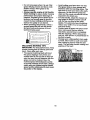
ments, check that both front links are
equal in length. Both links should be
approximately 10-3/8".
• If links are not equal in length, adjust
one link to same length as other link.
• To lower front of mower loosen nut =E"
on both front links an equal number of
turns.
• When distance "D" is 1/8" to 1/2" lower
at front than rear, tighten nuts "F"
against trunnion on both front links.
• To raise front of mower, loosen nut =F"
from trunnion on both front links.
"13ghten nut =E" on both front links an
equal number of turns.
• When distance "D" is 1/8" to 1/2" lower
at front than rear, tighten nut "F" against
trunnion on both front links.
• Recheck side-to-side adjustment.
>. oo. ,
_
=:_
Mandrel
Bottom
Bottom
of Cud "---"
(_
Both Front Links Should be Equal in Length
_
_
of Curl
Suspension
"E"
.
A_
Lift Link Adjustment Nut
FRONT-TO-BACK
ADJUSTMENT
IMPORTANT: Deck must be level side-toside. if the followingfront-to-back adjustment is necessary, be sure to adjust both
front links equally so mower will stay
level side-to-side.
To obtain the best cutting results, the
mower housing should be adjusted so that
the front is approximately 1/8" to 1/2"
lower than the roar when the mower is in
its highest position.
Check adjustment on dght side of tractor.
Measure distance "D" directly in front and
behind the mandrel at bottom edge of
mower housing as shown.
• Before making any necessary adjust!
Front Links
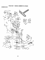
TO REPLACE
MOWER
BLADE
DRIVE
BELT (See IllustraUon Next Page)
The mower blade drive belt may be
replaced without tools. Park the tractor on
level sudace. Engage parking brake.
BELT REMOVAL• Remove mower from tractor (See "1"0
REMOVE MOWER" in this section of
this manual).
• Work belt off both mandrel putleys
idler pulleys.
• Pull belt away from mower.
24
and
BELTINSTALLATION• Installnewbolt in reverseorder of
removal.
• Make sure bolt is in all pulley grooves
and inside all belt guides.
• Install mower in reverse order of
removal instructions.
Idler
Pulleys
Mandrel
Pulley
Mandrel
Pulley
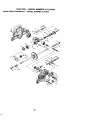
TO ADJUST BRAKE
.,
' TO REPLACE MOTION DRIVE BELT
Your tractor is equipped with an adjustable
brake system which is mounted on the
side of the transaxle,
If tractor requires more than six (6) feet
stopping distance at high speed in highest
gear, then brake must be adjusted.
• Depress clutch/brake pedal and engage
parking brake,
• Measure distance between brake operating arm and nut =A"on brake rod.
• If distance is other than 1-9/16", loosen
jam nut and turn nut "A" until distance
becomes 1-9/16". Retighten jam nut
against nut "A".
• Road test tractor for proper stopping
distance as stated above. Readjust if
necessary. If stopping distance is still
greater than six (6) feet in highest gear,
further maintenance is necessary.
Contact your nearest authorized sero
vice center/department.
Park the tractor on level surface. Engage
parking brake. For assistance, there is a
belt installation guide decal on bottom sid_
of left footrest.
• Remove mower (See "TO REMOVE
MOWER" in this section of this manual.)
• Remove belt from stationary idler and
clutching idler.
• Pull belt slack toward rear of tractor.
Carefully remove belt upwards from
transmission input pulley and over cooling fan blades.
• Pull belt toward front of tractor and
remove downward from around engine
pulley.
• Install new belt by reversing above procedure.
Engine
Pulley
Clutching Idler..--
With ParkingBrake
Jam
_
StationaryIdler_ "0
=Engaged"
Transmission
"A"
Do Not touch this nut. If further brake adjustment is necessary contact your nearest authorized service center/department
Input Pulley _
25
_.I_
TO ADJUST
MOTION
CONTROL
LEVER
The motion control lever has been preset
at the factory and adjustment should not
be necessary.
• Loosen adjustment bolt in front of the
right rear wheel, and lightly tighten.
• Start engine and move motion control
lever until tractor does not move forward
or backward.
• Hold motion control lever in that position
and turn engine off.
• While holding motion control lever in
place, loosen the adjustment bolt.
• Move motion control lever to the neutral
(N) (lock gate) position.
• Tighten adjustment bolt securely.
NOTE: If additional clearance is needed
to get to adjustment bolt, move mower
deck height to the lowest position.
After above adjustment is made, if the
tractor still creeps forward or backward
while motion control lever is in neutral
position, follow these steps:
• Loosen the adjustment bolt.
• Move the motion control lever 114 to 1/2
inch in the direction it is trying to creep.
• Tighten adjustment bolt securely.
• Start engine and test.
• If tractor still creeps, repeat above steps
until satisfied.
Motion Control Lever
wheel and reassemble per instructions in
the Assembly section of this manual.
FRONT WHEEL TOE-IN/CAMBER
The front wheel toe-in and camber are not
adjustable on your tractor. If damage has
occurred to affect the front wheel toe-in or
camber, contact your nearest authorized
service center.
TO REMOVE
:
FOR REPAIRS
• Block up axle securely.
• Remove axle cover, retaining ring and
washers to allow wheel removal (rear
wheel contains a square key - Do not
lose).
• Repair tire and reassemble.
• On rear wheels only: align grooves in
rear wheel hub and axle. Insert square
key.
• Replace washers and snap retaining
ring securely in axle groove.
• Replace axle cover.
NOTE: To seal tire punctures and prevent
flat tires due to slow leaks, tire sealant
may be purchased from your local parts
dealer. Tire sealant also prevents tire dry
rot and corrosion.
RetainiWn_Sh_
A
Neutral Lock
Axle Cover
,.
WHEEL
d Bolt
TO START
BATTERY
_
ENGINE
Square Key
(Rear Wheel Only)
WITH A WEAK
ACAUTION:
Lead-acid batteries generate explosive gases. Keep sparks, flame
and smoking materials away from batter3hould your transmission require removal
ies. Always wear eye protection when
or service or replacement, it should be
around batteries.
}urged after reinstallation and before
If your battery is too weak to start the
)perating the tractor. See =PURGE
engine,
it should be recharged. (See
IRANSMISSION"
in the Operation section
"BATrERY"
in the MAINTENANCE sec}f this manual.
tion
of
this
manual).
ro ADJUST STEERING
WHEEL ALIGNIf =jumper cables" are used for emergency
_ENT
starting,
follow this procedure:
f steering wheel crossbars are not horiIMPORTANT: Your tractor Is equipped
:ontal (left to right) when wheels are posiwith a 12 volt negative grounded system.
ioned straight forward, remove steering
The other vehicle must also be a 12 volt
negative grounded system. Do not use
26 your tractor battery to start other vehicles.
rRANSMISSION
_IENT
REMOVAL/REPLACE-
TO ATTACH JUMPER
CABLES
-
• Connect each end of the RED cable to
the POSITIVE (+) terminal of each battery, taking care not to short against
chassis.
• Connect one end of the BLACK cable to
the NEGATIVE (-) terminal
charged battery.
remaining hex bolt and keps nut.
Tighten
securely.
• Close terminal access doom.
• Close hood.
of fully
Hex Bolt
Terminal
• Connect the other end of the BLACK
cable to good CHASSIS GROUND,
away from fuel tank and battery.
TO REMOVE CABLES, REVERSE
ORDER • BLACK cable first from chassis and
then from the fully charged battery.
• RED cable last from both batteries.
Access
Door
Kep_ut
....._:..-----_._
_}_i---.
,--i.i°i
Termin_
Is
(Black)
Cable
=Positive" (+)
"Negative" (-)
L.H.Panel _-_1
/
Bolt
TO REPLACE HEADLIGHT
BULB
• Raise hood.
• Pull bulb holder out of the hole in the
backside of the grill.
• Replace bulb in holder and push bulb
holder securely back into the hole in the
backside of the grill.
• Close hood.
INTERLOCKS
REPLACING
BATTERY
&,CAUTION:
Do not short battery terminals by allowing a wrench or any other
object to contact both terminals at the
same time. Before connecting battery,
remove metal bracelets, wristwatch
bands,rings,etc.
Positive terminal must be connected first
AND RELAYS
Loose or damaged wiring may cause your
tractor to run poorly, stop running, or prevent it from starting.
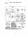
• Check wiring. See electrical wiring diagram in the Repair Parts section of this
manual.
TO REPLACE
FUSE
Replace with 30 amp automotive-type
plug-in fuse. The fuse holder is located
behind the dash.
to prevent sparking from accidental
grounding.
• Lift hood to raised position.
• Remove terminal guard.
• Disconnect BLACK battery cable then
RED battery Cable and carefully remove
battery from tractor.
• Install new battery with terminals in
same position as old battery.
• Reinstall terminal guard.
• First connect RED battery cable to positive (+) battery terminal with hex bolt
and keps nut as shown. Tighten secure-
ly.
• Connect BLACK grounding cable to
negative (-) battery terminal with
27
TO REMOVE HOOD AND GRILL ASSEMBLY
• Raise hood.
Unsnap headlight wire connector.
• Stand Jn front of tractor. Grasp hood at
sides, tilt toward engine and lift off of
tractor.
• To replace, reverse above procedures.
Clamp Screw
Quarter Circle
Connector
Choke Closed
Casing Clamp
Screw
ENGINE
Maintenance, repair, or replacement of the
emission control devices and systems,
which are being done at the customers
expense, may be performed by any nonroad engine repair establishment
or individual. Warranty repairs must be performed by an authorized engine manufacturer's service outlet.
TO ADJUST THROTTLE
CONTROL
CABLE
Choke Lever
TO ADJUST
CARBURETOR
The carburetor has been preset at the factory and adjustment should not be necessary. However, minor adjustment may be
required to compensate for differences in
fuel, temperature, altitude or load. If the
carburetor does need adjustment, proceed
as follows:
In general, turning the mixture screw in
(clockwise) decreases the supply of fuel to
the engine giving a leaner fuel/air mixture.
Turnin_ the mixture screw out (counterclockwzse) increases the supply of fuel to
the engine giving a richer fuel/air mixture.
IMPORTANT" Damage to the needles and
the seats in carburetor may result if screw
is turned in too tight.
The throttle control has been preset at the
factory and adjustment should not be necessary. Check adjustment as described
below before loosening cable, if adjustment is necessary, proceed as follows:
• With engine not running, move throttle
control lever to fast position.
• Check that swivel is against side of
quarter circle. If it is not, loosen cable
clamp screw and pull cable back until
swivel is against quarter circle. Tighten
cable clamp screw securely.
TO ADJUST CHOKE CONTROL
PRELIMINARY
The choke control has been preset at the
factory and adjustment should not be necessary. Check adjustment as described
below before loosening cable. If adjustment is necessary, proceed as follows:
• With engine not running, move choke
control (located on dash panel) to full
choke position.
• Remove air cleaner cover, filter and cartridge plate to expose carburetor choke
(see "AIR FILTER" in the Customer
Responsibilities
section of this manual).
• Choke should be closed. If it is not,
loosen casing clamp screw and move
choke cable until choke is completely
closed. Tighten casing clamp screw securely.
• Reassemble air cleaner.
SETTING
• Be sure you have a clean air filter, and
the throttle control cable and choke are
adjusted properly (see above).
• With engine off turn idle mixture screw
in (clockwise) closing it finger tight and
then turn out (counterclockwise)
1-1/4
to 1-1/2 turns.
FINAL SETTING
• Start engine and allow to warm for five
minutes. Make final adjustments with
engine running and shift/motion
control
lever in neutral (N) position.
• With throttle control lever in slow position, hold throttle lever a_ainst idle
speed screw and adjust idle speed
screw to obtain 1200 to 1400 RPM.
28
• While still holding throttle lever against
idle speed screw, tum idle mixture
screw in(clockwise)
until engine begins
to die and then turn out (countemlockwise) until engine runs rough. Tum
screw to a point midway between those
two positions.
• Continue to hold throttle lever against
idle speed screw and adjust idle speed
screw to obtain 900 to 1200 RPM. Release throttle lever.
engine-governed high speed needs
adjusting, contact your nearest authorized
service center/department,
which has
proper equipment and experience to make
any necessary adjustments.
Idle Speed
ACCELERATION
TEST
• Move throttle control lever from slow to
fast position. If engine hesitates or dies,
turn idle mixture screw out (counterclockwise) 118 turn. Repeat test and
continue to adjust, if necessary, until
engine accelerates smoothly.
High speed stop is factory adjusted. Do
not adjust - damage may result.
IMPORTANT:
Never tamper with the
engine govemor, which is factory set for
proper engine speed. Overspeeding the
engine above the factory high speed setting can be dangerous. If you think the
Immediately prepare your tractor for storage at the end of the season or if the tractor will not be used for 30 days or more.
,ACAUTION:
Never store the tractor with
gasoline in the tank inside a building
where fumes may reach an open flame or
spark. Allow the engine to cool before storing in any enclosure.
TRACTOR
Remove mower from tractor for winter
storage. This will allow you to clean it thoroughly. Remove all dirt, grease, leaves,
etc. Store in a clean, dry area.
• Clean entire tractor (See "CLEANING" in
the Maintenance section of this manual).
• Inspect and replace belts, if necessary
(See belt replacement instructions in the
Service and Adjustments section of this
manual).
• Lubricate as shown in the Maintenance
section of this manual.
• Be sure that all nuts, bolts and screws
are securely fastened. Inspect moving
parts for damage, breakage and wear.
Replace if necessary.
• Touch up all rusted or chipped paint surfaces; sand lightly before painting.
Idle Mixture Scre_
Throttle Lever
Idle Speed
_
Screw
Idle Mixture
Screw
Throttle Lever
BATTERY
• Fully charge the battery for storage.
• After a period of time in storage, battery
may require recharging.
• To help prevent corrosion and power
leakage during long periods of storage,
battery cables should be disconnected
and battery cleaned thoroughly (see =TO
CLEAN BATTERY AND TERMINALS"
in
the Maintenance section of this manual).
• After cleaning, leave cables disconnected and place cables where they cannot
come in contact with battery terminals.
• If battery is removed from tractor for
storage, do not store battery directly on
concrete or damp surfaces.
ENGINE
FUEL SYSTEM
IMPORTANT:
It is important to prevent
gum deposits from forming in essential fuel
system parts such as carburetor, fuel filter,
fuel hose, or tank during storage. Also,
experience indicates that alcohol blended
fuels (called gasohol or using ethanol or
methanol) can attract moisture which leads
to separation and formation of acids during
storage. Acidic gas can damage the fuel
system of an engine while in storage.
29
• Drainthe fueltank.
• Startthe engineand let it rununtilthe
OTHER
• Do not store gasoline from one season
to another.
• Replace your gasoline oan if it starts to
rust. Rust and/or dirt in your gasoline will
cause problems.
• If possible, store your tractor indoors.
and cover it to give protection from dust
and dirt.
fuel lines and carburetor are empty.
o Never use engine or carburetor cleaner
products in the fuel tank or permanent
damage may occur.
, Use fresh fuel next season.
NOTE: Fuel stabilizer is an acceptable
alternative in minimizing the formation of
fuel gum deposits during storage. Add stabilizer to gasoline in fuel tank or storage
container. Always follow the mix ratio
found on stabilizer container. Run engine
at least 10 minutes after adding stabilizer
to allow the stabilizer to reach the carbure-
• Cover your tractor with a suitable protective cover that does not retain moisture.
Do not use plastic. Plastic cannot
breathe, which allows condensation to
form and cause your tractor to rust.
IMPORTANT:
Never cover tractor while
:or. Do not drain the gas tank and carbureor if using fuel stabilizer.
engine and exhaust areas are still warm.
'NGINE OIL
_3rainoil (with engine warm) and replace
withclean engine oil. (See =ENGINE" in
the Maintenance section of this manual).
CYLINDER(S)
• Remove spark plug(s).
• Pour one ounce of oil through spark plug
hole(s) into cylinder(s).
• Turn ignition key to =START" position for
a few seconds to distribute oil.
• Replace with new spark plug(s).
30
"ROUBLESHOOTING
CHART
PROBLEM
Will not start
CAUSE
CORRECTION
• Out of fuel.
• Engine not'CHOKED" properly.
• Engine flooded.
• Fill fuel tank.
• See =TO START ENGINE" in
•
•
•
•
•
•
•
•
Bad spark plug.
Dirty air filter.
Dirty fuel filter.
Water in fuel.
•
•
•
•
•
Engine valves out of adjustment.
Dirty air tilter.
Bad spark plug.,
Weak or dead battery.
Dirty fuel filter.
Stale or dirty fuel.
•
•
•
•
•
• Loose or damaged wiring.
• Carburetor out of adjustment.
Engine valves out of adjustmenL
Engine will not tum
ore r
• Clutch/brake pedal not
depressed.
• Attachment clutch is engaged.
• Weak or dead battery.
• Blown fuse.
•
•
•
•
attempting to start.
Replace spark plug.
Clean/raplace air filter.
Replace fuel filter.
Drain fuel tank and carburetor,
refill tank with fresh
gasoline and replace fuel filter.
• Check all wiring.
• See -ToAdjust Carburetor" in
Service and Adjustments
secfion.
• Contact an authorized service
center.
• Loose or damaged wiring.
• Carburetor out of adjustment.
Hard to start
Operation section.
• Wait several minutes before
Clean/replace air tilter.
Replace spark plug.
Recharge or replace battery.
Replace fuel tilter.
Drain fuel tank and refill with
fresh gasoline.
• Check all wiring.
• See "ToAdjust Carburetof" in
Service and Adjustments
section.
• Contact an authorized service
center.
• Depress clutch/brake pedal.
Faulty operator presence
switch(as).
Disengage attachment clutch.
Recharge or replace battery.
Replace fuse.
Clean battery terminals.
Check all wiring.
Check/replace ignition switch.
Checldreplace solenoid or
starter.
• Contact an authorized service
center.
Weak or dead battery.
Corroded battery terminals.
Loose or damaged wiring.
Faulty solenoid or starter.
•
•
•
•
Corroded battery terminals.
Loose or damaged wiring.
Faulty ignition switch.
Faulty solenoid or starter.
Engine clicks but will
not start
•
•
•
•
Loss oi power
• Cutting too much grass/too
fast.
• Throttle in "CHOKE" position.
31
•
•
•
•
•
•
•
Recharge or replace battery.
Clean battery terminals.
Check all widng.
Check/replace solenoid or
starter.
• Set in =Higher Cut* posltionireduse speed.
• Adjust throttle control.
TROUBLESHOOTING CHART
PROBLEM
CAUSE
CORRECTION
Loss of power (cont,d)
• Build-up of grass, leaves and
trash under mower.
• Dirty air tilter.
• Low oil level/dirty oil.
• Faulty spark plug.
• Clean underside of mower hous-
• Dirty fuel filter.
• Stale or dirty fuel.
• Water in fuel.
• Spark plug wire loose.
•
•
•
•
Excessive vibration
Dirty engine air screen/fins.
Dirty/clogged muffler.
Loose or damaged wiring.
Carburetor out of adjustment.
• Engine valves out of adjustment.
• Worn, bent or loose blade.
• Bent blade mandrel
• Loose/damaged part(s).
Engine continues to
run when operator
leaves seat with attachment clutch
engaged
Poor cut - uneven
• Faulty operator-safety presence control system.
• Worn, bent or loose blade.
• Mower deck not level.
• Buildup of grass, leaves, and
trash under mower.
• Bent blade mandrel.
Mower blades will not
rotate
Poor grass discharge
• Clogged mower deck vent
holes from buildup of
grass, leaves, and trash
around mandrels.
• Obstruction in clutch mechanism.
ing.
• Clean/replace air tilter.
• Check oil level/change oil.
• Clean and regap or change
spark plug.
• Replace fuel filter.
• Drain fuel tank and refill with
fresh gasoline.
• Drain fuel tank and carburetor,
refill tank with fresh gasoline and
replace fuel filter.
• Connect and tighten spark plug
wire.
• Clean engine air screen/fins.
• Clean/replace muffler.
• Check all widng.
• See =ToAdjust Carburetor_ in
Service and Adjustments
section.
• Contact an authorized service
center.
• Replace blade. Tighten blade
bolt.
• Replace blade mandrel.
• Tighten loose part(s). Replace
dama_led pads.
• Check wiring, switches and connections. If not
corrected, contact an authorized
service center/
department.
• Replace blade. Tighten blade
boR.
• Level mower deck.
i ° Clean underside of mower housing.
• Replace blade mandrel.
• Clean around mandrels to open
vent holes.
• Remove obstruction.
• Worn/damaged mower ddve
belt.
• Replace mower ddve belL
• Frozen idler pulley.
• Frozen blade mandrel.
• Replace idler pulley.
• Replace blade mandrel.
• Place throttle control in =FAST"
• Engine speed too slow.
• Travel speed too fast.
• Wet grass.
32
position.
• Shift to slower speed.
• Allow grass to dry before mowing.
TROUBLESHOOTING CHART
PROBLEM
CAUSE
Poorgrassdischarge • Mowerdecknotlevel.
! (cont'd)
• Low/uneven tire air pressure.
• Worn, bent or loose blade.
• Buildup of grass, leaves and
trash under mower.
• Mower drive belt worn.
• Blades improperly installed.
• Improper blades used.
Headlight(s) not
working (if so
equipped)
Battery will not
charge
Loss of ddve
Engine "backfires"
when turning engine
"OFF"
• Clogged mower deck vent
holes from buildup of
grass, leaves, and trash
around mandrels.
• Switch is "OFF".
I • Bulb(s) burned out.
• Faulty light switch.
• Loose or damaged wiring.
_ Blown fuse.
Bad battery ceU(s).
• Poor cable connections.
CORRECTION
• Level mower deck.
• Check tires for proper air pressure.
• Replace/sharpen blade. Tighten
blade bolt.
• Clean underside of mower housing.
• Replace mower ddve belt.
• Reinstall blades sharp edge
down.
• Replace with blades listed in thi:
manual.
• Clean around mandrels to open
vent holes.
•Tum
switch "ON'.
Check/replace
Replace bulb(s),light switch.
Check wiringand connections.
• Replace fuse.
• Replace battery,
• Check/clean all connections.
• Faulty regulator (if so
equipped).
• Replace regulator.
• Faulty alternator.
• Freewheel control in "disen-
• Replace altemator.
• Place freewheel control in
gaged" position.
• Motion drive belt worn, damaged or broken.
• Air trapped in transmission
during shipment
or servicin9.
• Engine throttle control not set
at "SLOW" position for 30
seconds before stopping
engine.
"engaged" position.
• Replace motion ddve belt.
33
Purge transmission.
Move throttle control to "SLOW"
position and allow to idle for 30
seconds before stopping engine.
TRACTOR -- MODEL NUMBER 917.270840
,LECTRICAL
41
25
I
I
I
TRACTOR
- - MODEL
NUMBER
ELECTRICAL
KEY
PART
NO.
NO.
DESCRIPTION
1 163465
Batten/
2 74760412
Bolt, Hex 1/4-20x3/4
8 7603J
Tray, Battery
10 145211
Bolt, BtrFront 114-20x7-1/2
11 150109
Holddown Batten/FrOnt Mount
12 145769
Nut, Push NylonBattery Front 1/4
16
153664
Switch IntedockPush-In
19 STD551125
Washer, Lock 1/4
20
73350400
Nut, Hex, Jam 1/4-20
21
166182
Harness, LightSocket (w14152J}
22 4152J
Light Bulb
24 4799J
Cable, Batten/
25
146148
Cable, Batten/
26
166180
Fuse
27 73510400
Nut Keps Hex 1/4-20 Unc
28
145491
Cable, Ground
29
121305X
Switch, Seat
30 140301
Switch, Ignition4 Position
31
124211X
Nut, Ignition
32
141228
Cover, IgnitionSwitch
33
109310X
Key, Molded, Craftsman
40
166145
Harness, Ignition
41
71110408
Bolt BIk Fin Hex 1/4.20 UNC x 1/2
42
131563
Cover, Terminal
43
168327
Solenoid
44 73640400
NutKepsEgkHex 1/4-20UNC
45
121433X
Ammeter Rectangular6 Amp
52
141940
Protent'_n W'treLoop (Hour Meter)
55
17490508
ScrewThdrol 5/16-18xl/2
70
166658
Harness Engine B&S
NOTE: Allcomponent dimensionsgiven in U.S. inches
linch = 25.4 mm
35
917.270840
TRACTOR
- - MODEL
NUMBER
917.270840
CHASSIS AND ENCLOSURES
28
12
58
S3
31'
23
54
6O
14
36
TRACTOR - - MODEL NUMBER 917.270840
CHASSIS AND ENCLOSURES
KEY
NO.
1
2
3
4
5
9
10
11
12
13
14
17
18
20
23
25
25
28
29
30
31
37
38
39
51
52
53
54
55
57
58
60
64
74
140
142
143
144
145
159
PART
NO.
DESCRIPTION
Chassis
165583
140356
Drawbar
17490612
Screw,Thd., Roll. 3/8-16 x 3/4TypeTr
STD551025
Washer 13/32 x 3/4 x 16 Gauge
155272
BumperHood/Dash
161917X013
Dash, Silkscreanod
STD533710
Bolt,Carriage 3/8-16 x 1
155927
Panel, Dash, LH
145660
Clip Tinnennan GrilleP/l_
155936
Panel, Dash, RH
17490608
Screw,Thd., Ro_. 3/8-16 x 1/2 Type "IF
144983X558
Hood Assembly
Burnber Hood
126938X
156437
Plata Mto Batted/Fuel Tank
124028X
Bushing,Snap, Nylon, Fue4Une
19131312
Washer 13/32 x 13/16 x 12 Gauge
STD541437 • Locknut,Hex, with Insert 3/8-16 UNC
145198X558
Grille,w/Cnps MS-558
155217
Lens, Grille
154791X558
Fender/Footrest
139976
Bracket,Fender/Support
17490508
Screw, ThdroL 5/16o18 x 1/2 TYT
139886
Pivot BracketAssembly,LH, Mower, Rear
139887
PivotBracketAssembly, RH, Mower, Rear
73800400
Nut LockW/Insert 1/4 - 20 UNC
19091416
Washer 9/32 X 7/8 X 16 Ga.
BracketGrille PickoflLH
145201
161464
Screw, HexWshd #8-18 x 7/8
145202
BracketGdlle PickoffRH
STD552507
BoltFinHex 1/4 -20 UNC X.75
140547
Air Duct P/L 18HP B&S Opp. Twin
72140606
Bolt Rdhd Sqnk 3/8-16 UNC x 3/4
Dash Lower STLT
-"
154798
Nut Crawniock3/8-16 UNC STD541437
158418
BracketSuspensionFront
165867
Plate ReinforcementSTLT
154966
BracketSwaybar Chassis
154207
BracketFootrest STLT
156524
Rod PivotChassis/Hood
155123X428
CupholderStirBlack
NOTE: All component dimensionsgiven in U.S. inches
1 irtch= 25A mm
37
TRACTOR - - MODEL NUMBER 917.270840
;ROUNDDRIVE
115
71
;156
147
1M
38"-_
32
/30
16
_
103
02
97
62
16
' _ 98
3O
61
.146
27
84
38
TRACTOR- - MODEL NUMBER 917.270840
GROUND
KEY
NO.
DRIVE
PART
NO.
2
3
B
10
14
15
16
142431
143995
165866
STD561210
10040400
74490544
STD541431
18
STD523710
19
STD541437
21
22
24
25
26
27
28
29
30
32
34
35
36
37
38
39
40
41
42
130564
145627
73350600
10_888X
STD551037
STD561210
1452O4
124236X
130807
74760512
155071
120183X
19211616
1572H
131494
s'rD523727
4470J
165838
19131312
43
47
48
49
50
51
52
53
55
56
57
59
61
19111012
127783
154407
123205X
STD523715
STD541437
S'rD541431
105710X
105709X
STD523712
14O294
140312
17490612
62
63
64
65
66
70
71
72
73
8883R
140186
71170764
$TD551143
154778
134683
140158
19132012
156347
DESCRIPTION
KEY
NO.
Tmnsaxla (See Breakdown)
Hydro Gr 319-0650
Spring,Return, Brake
Pulley,Transaxle
Rod Shift Fender A_uet
PinCotter 1/8x 1 CAD
Washer Lock Hvy Helical
BoltHexRghd 5/16-18Gr. 5
Nut Lock Hex W/Ins. 5/16-18
Unc
BoltFin Hex 3/8-16 Unc x I
Gr. 5
NutLockHexW/Wsh 3/8-16
Uric
Knob, Deluxe 1/2-13
Rod, Brake Hydro
Nut, He)(Jam .3/8-16 Uric
Spdng, Brake Rod
Washer
Pin Cotter 1/8 x 3/4 CAD.
Rod, PaddngBrake
Cap, ParldngBrake
BraCket,Transax_
BoitHexHd 5/16-18Uncx3/4
Shaft,Foot Pedal
Beadng, Nylon
Washer
Pin, Roll
Pulley,Idler, Flat
Bott
Spacer, Split
Keeper, Belt Idler
Washer 13/32 x 13/16 x 12
Gauge
Washer 11/32 x 5/8 x 12 Ga.
Puney,Idler, V-Groove :
BellcrankClutch Grad Dn:,STL
Retainer,Belt
Bolt
Nut Crownlock 3/6-16 UNC
Nut, Crowntock 5/16-18Unc
Unk, Clutch
Spdng, Return, Clutch
BottHex 3/6-16x1-1/4
V-Belt, Ground Drive
Keeper, Center Span
ScrewThdrol. 3/6-16 x 3/41¥
"Fr
Cover, Pedal
Pulley, Engine
Bolt Hex 7116-20 x 4 Gr. 5
Washer
Keeper Belt Engine Hydro:
Guide Belt RH F_r@ne
Strap Toro,ue Lh Hydre 18/20" T
Washer 13/32 x 1-1/4 x 12.Ga.
StrapTolque Rh Hydro
PART
NO.
DESCRIPTION
74
75
121199X
121749X
Spacer, Split
Washer 25132x 1-1/4 x 16
76
77
78
STD581075
123583X
121748X
81
165591
82
83
84
86
87
88
89
90
91
92
93
94
95
96
97
165711
19171216
165815
71206
19212016
12000008
164890X428
124346X
74780536
74780524
142564
140462
144643
4497H
140469
98
100
102
73510600
19111216
141322
103
73940800
104
105
106
140156
71070516
74780520
GaL_e
E-Ring
Key,Square
Washer 25/32 x 1-5/8 x 16
Gauge
ShaftAsm Cross Tapered 650
20
Spdng Torsion
Washer 17/32 x 3/4 x 16 Ga.
Link Trensaxla 0650 LTHT/STL
Bo,_ng
_r
21/32 x 1-1/4 x 16 Ga.
Ring Klip #5.304..62
Console, Shttt
Nut Self-Tl_ Wsh-he 1/4 Zinc
Bolt Rn Hex 5/16-18 x 2-1/4
Bolt Fin Hex 5/6-18 Unc x 1-1/2
Line Fuel Hydro 4"
Fen,Hydro 7"
ControlBypassHydro 20""liras
Retainer Spring 1" 23nc/Cad
Keeper Bolt Rh Hydro 0750.
18/20"
Nut Keps Hex 3/8-16 Unc
Washer 11/32 x 3/4 x 16 Ga.
Washer BelM'ite .501D x
1.601)
Nut Hex Jam Toplock 1/4-20
Unf
Arm,Contr_ Hydro
Screw Cap Hex 5/16x 18 x 1
BoftFin Hex 5/16-18 Unc x 11/4
Bolt Cart. 3/6-16 x 1.25
116 72110610
Washer 11/32 x 5/8 x 16 Ga.
144 19111016
BushingBeitcrenkGn_ Drive
150 165850
Washer 13/32 x 2 x 10 Ga.
151 19133210
Washer Srrted 5/161D x 1.125
156 166002
ButtShoulder 5/16-18 Unc- 2A
157 153236
BracketShift Mount
158 165589
HubTappered Range Shift Lt
159 165494
Washer 29/32 x 1-1/4 x 16 Ga
160 19292016
BoltRdhd Sqnk 1/4-20 x 3/4 Gr
161 72140406
5
NUtCrownlockl/4-20 Unc
162 73680400
BoltHex Fin 1/4-20 Unc x I Gr
163 74780416
5
Washer 5/8 x .281 xl0Ga
164
19091010
Bracket Pivot Lever
165 165623
Screw 5/1 6-18 x 5/8
166
166880
Bolt Shoulder 5/16-18 x .561
168 165492
Plate FasteningLt
169 165580
Screw
Thdrel 3/8-16 x 1/2 Ty-Tt
171 17490608
NOTE: Allcomponent dimensionsgiven in U.S. inches
1 Inch= 25A mm
39
TRACTOR - - MODEL NUMBER 917.270840
STEERINGASSEMBLY
"-------
Ikl
,
._.s
I
s1_$
4
40
TRACTOR
- - MODEL
NUMBER
917.270840
STEERING ASSEMBLY
KEY
NO.
PART
NO.
1 139768
2 154427
3 156483
4
157473
5 6266H
6
121748X
7 19272016
8 12000029
9 3366R
10
156438
11 STD551137
13
154779
15 73901000
17 156546
18 57079
19
160395
22
165857
23
165851
25
154406
26
126847X
27
136874
28
19131416
29
17490612
30
STD561210
32
130465
36
155O99
37
152927
38
139769
39
19133808
40
STD541537
41
100711L
42
145054
43
121749X
44
153720
46 : 121232X
47- 6855M
51 73800500
54 74780520
62
156594
63 74780616
65
154780
66
154404
67 74781044
68
154429
79
19132012
80
74950612
DESCRIPTION
Steering Wheel
FrontAxle Assembly
Sp'_ndLe
Assembly,LH.
Spindle Assembly,R.H.
Bearing, Race, Thrust, Hardened
Washer 25/32 x 1-5/8 x 16 Gauge
Washer 27/32 x 1-1/4 x 16 Gauge
Ring, Klip
Bearing,Steering Column
t__k, Omg
Washer, Lock
Spacer, Bearing, Front A,,de
NuL Lock, Range 5/8-11 UNC
Shaft Assembly,Steering
Washer, Thrust .515 x .750 x .033
Support, Shaft
Screw hex Wshhd Torx
PlttmanShaft Assembly
Bracket, Steenng
Bushing,Link, Drag
Gear, Sector
Washer 13/32 x 7/8 x 16 Gauge
Screw, Thd., Roll.3/8-16 x 3/4
Pin
Rod, "Re
Bush'_g, Steering
Screw 1-1"#10-32x 5 x 3/8 Flange
insert, SteeringWheel
Washer 13/32 x 2-3/8 x 8 Gauge
GripcoNut
Adaptor,Steering Wheel
Boot, Steedng Dash P/L Mtl BIk
Washer 25/32 x 1-1/4 x 16 Gauge
ExtensionSteedng Non-Adjust
Cap, Spk_e
Fitting,Grease
Nut LockHx W/Ins 5/16-18 UNC
Bolt Fin Hex 5/16-18 UNC x 1-1/4
Kit, SteeringAssembly,Service
BoltFin Hex 3/8-16 unc. x 1 Gr. 5
Spacer Axle
BearingArm Pittman
BoltRn Hex 5/8-11unc x 2o3/4
BraceA)de
Washer 13/32 x 1-1/4 x 12 Ga
Bolt Hex Nylon3/8-16 x 3/4
NOTE: Allcomponent dimensionsgiven in U.S. inches
1 inch= 25A mm
41
TRACTOR
- - MODEL
NUMBER
917.270840
NGINE
_"'_
26
17
17
i
i
31
39
29
/
4
OPTIONAL
EQUIPMENT
Spark Arrester
42
TRACTOR
- - MODEL
NUMBER
917.270840
ENGINE
KEY
NO.
1
2
PART
NO.
DESCRIPTION
162152
17720410
4
5
6
7
8
10
11
12
13
14
15
16
17
23
25
26
27
29
31
32
33
34
35
37
149723
144069
144O68
138129
150176
145552
STD551125
STD522507
272250
13280336
13200300
STD551237
17490624
159880
145996
73920600
152927
137180
157103
161696
12348"/X
106082X
17490512
8543R
38
=o
39
40
41
81
109227X
3645,1
139277
128861
....
.
ControlThrot Paddle 32 22
Screw Hex Thd Cut 1/4-20x5/8 T
Engine (Sea Breakdown) BdggsModel No. 461707_0145-E1
MufflerF_Jd_aust
Exhaust Asm. Left
Exhaust Asm. Right
Clamp Tube Double Engine
Bolt 5/16 - 18 UNC X 3/4 W/Sems
Heat Shield Lt
Washer Lock Hvy. Helical 1/4
. BoltFin Hex 1/4-20 x 3/4
Gasket Muffler
NipplePipe 4-1/2"
ElbowStd 90 Degree 3/8-18 Npt
Washer Lock ExtTooth3/8
Screw Thdrol 3/8-16xl -1/2 Tytt
Sh'_id Brownk_;_:)ebris Guard
ControlChoke
Nut Keps 3/8-24 Unf
Screw TT#10-32 x 5 x 3/8 Flange
ArrestorSpark
Tank Fuel 3 50 Rear
Cap FuelGuage STLT
Oarm HoseB_
Spacer Pad
Screw Thdro_5/16-18 x 3/4 TYT
Lk_eFuel
PlugOil Drain (Order From Engine Manufacturer)
Pad Idler 1.75 x .75 x .06
B.sr
Stem Tank Fuel
Nut, Range 1/4-20 Slatter Nut
NO'r_ AI conlponent dimensions _ven JnU.,_
1 Inch: 25A mm
43
TRACTOR - - MODEL NUMBER 917.270840
SEATASSEMBLY
21
KEY
NO.
1
2
3
4
5
6
7
8
9
10
11
PART
NO.
DESCRIPTION
140123
140551
74760616
19131610
145006
STD541437
124181X
17490616
19131614
155925
166369
Seat 3450 BIk/'olkCraftsman
BracketPet PivotSeat (blk)
BOllFin Hex 3/8-16unc X 1
Washer 13/32 X 3/4 X 10 Ga
Clip Push In Hinged
Nut Hex Lockw/Ins 3/6-16 Uns
Spdng Seat Cprsn 2 250 BIkZi
Screw Thdrol3/8.16 X 1Ty-tt
Washer 13/32 X 1 X 14 Ga
Pan Pnt Seat (blk)
KnobSeat
KEY
NO.
12
13
14
15
16
17
21
22
24
25
PART
NO.
121246X
121248X
72050412
134300
121250X
123976X
153236
STD541431
19171912
127018X
DESCRIPTION
BracketPnt Moun_ Switch
BushingSnap BlkNy150 Id
BoltRdhd Sht Nk 1/4-20x1-1/2
Spacer
s_128 x 9s_nc
SpdngCprsn 1 27 BI_ Pnt
NutLock 1/4 Lge Rg Gr 5 Zinc
BoltShoulder5/16-18 Unc.2A
NutHex Lock w/lns 5/16-18
Washer 17/32 X 1-3/16 X 12 Ga.
BoltShoulder 5/16-18 X 52
NOTE: Allcomponent dimensions given in U.S. inchesl inch = 25.4 mm
44
TRACTOR
-- MODEL
NUMBER
917.270840
DECALS
6
2
7
11
3
2
9
2O
22
19
14
14
13
KEY
NO.
PART
NO.
1
2
3
4
5
6
156439
163205
163200
163202
2735o3
133644
7
9
11
167181
163204
156811
13
146046
KEY
NO.
DESCRIPTION
Decal Fender Danger Sears
Decal Fend AutoSears Gold
Decal Hood Rh Craftsman
Decal Hood Lh Craftsman
Decal HP Engine
Decal Maint Customer
Scars Dom
Decal Replacement Sis
Decal FenderCraftsman Gold
Decal Fender STLTH Opar
last F_JS
Decal V-belt Dr Sch Tractor E
WHEELS & TIRES
PART
NO.
14
15
19
20
22
---
166927
160396
138047
166887
149516
138311
142341
-----
154515
154516
166711
166712
KEY
NO.
PART
NO.
1
2
3
4
59192
65139
106222X
59904
5
6
106732X427
278H
7
9040H
4,10
DESCRIPTION
Decal Dash Panel
Decal Mower Drive Schematic
Decal, Battery Diehard Scars
Decal Deck Mower EZ3
Decal Battery
Decal LiftHandle
Decal, Drawbar Cntd. MvL
Hyd. U.
Pad Footre_ Lh STLT
Pad Footrest Rh STLT
Manual, Owner's (English)
Manual, Owner's (Spanish)
DESCRIPTION
Valve Cap, Tire
Stem, Valve
Tire, Front
Tube, Front Tire
(Not Provided,Service Item
one)
Rim, Front
Fitting,Grease (Front Wheel
o_y)
11
Bearing, Flange (Front Wheel
On_y)
H
8
9
10
106108X427
122082X
7152J
11
--
104757X
144334
Rim, Rear
Tire, Rear
Tube, RcarTire
(Not Provided,Sen,ice Item
Only)
Cap, Axle
Sealant, Tire (10 oz. Tube)
NOTE: Allcomponent dimensionsgiven in U.S. inches
1 inch= 25.4 mm
45
TRACTOR - - MODEL NUMBER
917.270840
.IFT ASSEMBLY
29_
27
23
49
30
3
4
6
13
19
3
20
/
15
_,.\
._
1718
16\\
19
15
46
20
\ _
TRACTOR
- - MODEL
NUMBER
917.270840
LIFT ASSEMBLY
KEY
NO.
I
2
3
4
5
6
7
8
11
12
13
15
16
17
18
19
20
23
24
25
26
27
28
29
30
31
32
36
37
38
40
41
49
50
PART
NO.
DESCRIPTION
159460
159471
105767X
12000002
19211621
120183X
125631X
122365X
139865
139866
STD624008
127218
73350800
130171
73680800
139868
163552
110807X
19131016
2876H
76020308
126971X
73350600
138057
150233
140302
73540600
155097
123935X
17490512
19112410
155098
145212
110452X
LiftLever Inner Wke Asm.
ShaftAsm. Lift
Pin Groove
E Fling
Washer 21/32 x I x 21 Ga,
Bearing Nylong
Grip Handle Fluted
ButtonPlunger Read
LinkA.smLift LH.
UnkAsm Lift R.H.
Retainer Spdng
Link Front
Nut Jam Hex 1/2-13 Unc
Trunnion BIk Zinc
Nut Lock W/Wsh 1/2-13 Unc
Arm Suspension Mower
Retainer Spring
Nut, Special
Washer 13i32xSi8x16Ga.
Spdng
Pin, Cotter 3/32 x 1/2
Rod, Adjust Life
Nut, HexJam 3/8-16UNC
Knob, InfiniteHeightAdmustment
Trunnion, Inf. Heigh_
Bearing, PvI. Lift. Spherical
Nut Crowrdock3/8-24
Pointer Height Indicator
Plug Hole BIk 1.485H.515 Dia
Screw Thdrot 5/1&18 x 3/4
Washer 11/32 x 1-1/2 x 10 Ga
IndicatorHeight Stlt
Nut, Flex Flange Lock
Nut, Push Fnne. & Og
NOTE:Allcomponent
d_'nensions
glvenin U.S. inches
1 inch= 25.4 mm
47
TRACTOR - - MODEL NUMBER
917.270840
MOWER DECK
73
78
179
71
//
81
34
31
58
17
w-21
>21
21 22
_/'_23
24
\
16
28
29
,18
10_
9_
48
"
27
TRACTOR - - MODEL NUMBER
917.270840
MOWER DECK
KEY
NO.
PART
NO.
1
2
3
164961
STD533107
138017
4
5
6
8
9
10
11
12
13
138440
STD624008
130832
850857
STD551137
140296
134149
129895
137645
14
15
16
17
18
19
20
21
22
23
24
25
26
27
28
29
30
31
32
33
34
35
36
37
40
41
43
44
45
46
48
49
50
51
52
53
54
55
56
58
128774
110485X
140329
72110610
72140505
132827
159770
STD541431
134753
131267
105304X
123713X
110452X
130968
19111016
131491
157722
129963
153535
137266
STD533717
133835
131494
19131316
STD541437
133551
140083
140088
STD624O63
137729
133944
155066
131340
STD541410
139888
131845X900
133943
155046
122052X
140086
DESCRIPTION
KEY
NO.
Mower Housing
Bolt
Bracket Assembly,SwayBar,
Front
BracketAssembly, Sway Bar
Retainer Spdng
Arm, Suspension, Rear
Belt, Hex 3/8-24 x 1.25 Gr. 8
Washer, Lock
Washer, Hardened
Blade, Mulching
_a_ng, Ball
Shalt Assembly, Mandrel,
Vented (Incl. Key Number 6)
Housing,Mandrel, Vented
Baaing,BaU, Mandrel
Stripper,Vented Mower Deck
Bolt, Carriage 3/8-16 x 2-1/4
Bolt, Carriage 5/16.18 x 5/8
Bolt, Shoulder
Baffle, Vortex
Nut, Crownlock 5/16-18 UNC
Stiffener Bracket
Bracket, Deltector
Cap, Sleeve
Spring,Torsion,Deflector
Nut, Push
Shield, Deflector
Washer 11/32x5/8x 16 Ga.
Rod, Hinge
Screw Thdrol RollingWsh Hd
Washer, Spacer
Pulley, Mandrel
Nut, Toplock, Ranged
Bolt
Fastner, Christmas'tree
Pulley, Idler, Rat
Washer 13i32x13/16x 16Ga.
Nut, Crownlock3/8-16UNC
Rod, Pivot, with _tbs
Rod, Clutch, Secondary, w/Nibs
Guard, Mandrel, L.H.
Retainer
Screw.Thd. Roll 1/4-20 x 5/8
Washer, Hardened
RollarAssembly, Cam Follower
Bolt. Shoulder #10-24 Grade 5
Locknut
Bolt, Shoulder 5/16-18 UNC
Arm Assembly, Pad, Brake
Washer, Hardened
Arm, Idler
Spacer, Retainer
Spring, TorsionBrakes 42"
PART
NO.
59
67
68
71
72
73
74
75
76
141043
162113
144200
142427
131870
127847
121748X
12000029
128903
77
78
79
80
81
82
83
84
55
92
127845
160570
127498
153701
73350600
142028
120958X
156084
72140620
STD541437
101
102
103
104
105
106
111
112
113
114
115
116
117
118
119
121
128
129
130
136420
71161010
19061216
STD551110
160793
2029J
155197
155198
17490512
73510500
72110504
4898H
165746
73930600
19121414
143723
153390
19131312
STD523710
131
132
141
--
STD533710
19132203
6266H
130794
--
164963
DESCRIPTION
Guard, Tuv Idler (94)
Knob CustomOval
V-BOlt
Pod, Clutch, Pdmary,wRh N_s
Spring, Return
Arm, Clutch, Secondary
Washer 25/32 x 1-5/8 x 16 Ga.
_ng. _p
Bolt, Shoulder 3/8-16 UNC x
1.44
Keeper, Spring
Arm,CkRch, Prk_a_y
Bushing,Large, Brass
Spdng, Mower Clutch
Nut, Hex Jam 3/8-16 UNC
TnlnnionAdj. 94
Washer Sintered
Keeper Bait Idler
Bolt Carriage :_J8-16x 2-1/2
Lockr,ut, Hex W/WSh 3/8-16
UNC
Cover Mulching42" Black
Sorew Truss Hd Phil10-24 x5/8
Washer #10
Washer Lock
LatchAsm Bagger
Nut Weld
BracketGauge, Wheel LH
Bracket, Gauge, Wheel RH
Screw Thdrol 5/16.18 x 3/4
Nut, Hex Keps 5/16-18 UNC
Bolt, Carriage 5/16 UNC x 1/2
Bolt, Shoulder
Wheel, Gauge
Nut, Cmwelock 3/8-16
Washer 13/32 x 7/8 x 14 Ga.
Bracket
Washer Felt
Washer 13/32 x 13/16 x 12 Ga.
i_)tt, Rn Hex 3/8-16 UNC x 1
Gr. 5
Bolt Rdhd Sqnk 3/8-16 UNC x 1
Washer 13/32 x 1-3/8 x 3 Ga.
Washer'thrust .75 x 1.230
MandrelAssembly (Includes
Key Numbers8-10, 12-15, 31
and 32)
Mower Deck, Complete (Std
deck - orderseparately mulcher
plate componentskey nos. 101106)
NOTE: Allcomponent dimensionsgiven in U.S.inches
1 inch= 25,4 mm
49
TRACTOR - - MODEL NUMBER 917.270840
IYDRO GEAR TRANSAXLE - - MODEL NUMBER 319-0650
28
59
23
17
4
5O
TRACTOR - - MODEL NUMBER
917.270840
HYDRO GEAR TRANSAXLE - - MODEL NUMBER 319-0650
KEY
NO.
PART
NO.
DESCRIPTION
1
2
3
4
5
6
7
8
9
13
14
15
17
18
19
23
24
25
26
27
28
29
30
34
142930
142931
142932
142928
142933
142934
142935
150771
142937
142938
142939
142940
142941
150772
150773
142944
142945
142946
150774
142948
142949
142950
150787
142951
Housing,Lower
Assembly,Upper Housing
Seal, Lip
Ring, Wire Retaining
Ring, Retaining
Beadng, Shaft Ball
Bearing, Cradle
Beadng, Thrust 30 x 52 x 13
Sweshplete, Variable
Block,CylinderAssembly
Arm, Trunnion
Seal, Lip
Guide, Slot
Shaft, Motor
Bearing, Thrust 42x68x16
Block, CylinderAssembly
Seal, Lip 10 x 25 x 7
Actuator, Bypass
Center Section AssemblyKit
Seal, Lip 26x42x8
Ring, Retaining
Washer 26 x 35 x 1
Plate, Bypass
OilF_erElement
35
36
37
38
39
40
41
142952
142953
142954
142955
150777
150778
142958
Arm, Bypass
Ring, Retaining
Arm,Actuating
Pin, Actuating
Bolt 5/16-24 x 1-3/4
Locknut,Hex 5/16-24UNJC
Brake RotodStatorKit
KEY
NO.
PART
NO.
DESCRIPTION
43
44
52
53
56
58
59
62
63
64
68
69
83
85
88
89
90
91
92
93
113
114
119
134
142884
150829
142991
142961
142963
142964
142965
142966
142967
142920
142969
144610
142971
150806
142973
142974
142975
142976
142977
142978
142917
142918
142980
144607
Washer 7/16 x 7/8 x .060
DifferentialAssembly
Washer 3/4 x 1.5 x .13
Seal .75 x 1.25 x .250
Shaft, Input
Bolt 1/4-20 x 1.38
Pin .50D x .43 ID x .750
Arm, Control
Puck, Dampener
Set Screw
Spring
Stud 5/16-24
JackshaftAssembly
Jackshaft
Screw, Cap
Washer 7/16 x I x 1/2
Sleeve Baadng
Seal, Wiper
Spdng, Block
Washer, BlockThrust
Cap, VentAssembly
Fitting,O-Ring Assembly
Spacer
Nut, Castle 5/'16-24
135
139
140
144608
150775
150776
Pin, Cotter
Spring,Compression
Nut, Hex 5/16-24
NOTE: All componentdl_
1 inch=25,4mm
51
given in U.S. inches
TRACTOR
- - MODEL
BRIGGS & STRATTON ENGINE-MODEL
NUMBER
917.270840
NUMBER 461707, TYPE NUMBER 0145-E1
5
552A
552 @
404 o
2set
113:
15 _
11010LABEL
Krr J
11058
OWNER'S MANUAL
"k REQUIRES
SPECIAL TOOLS
10 INSTALL SEEREPAIR
INSTRUCTION
52
MANUAL
I
TRACTOR
- - MODEL
BRIGGS & STRATTON ENGINE-MODEL
NUMBER
917.270840
NUMBER 461707, TYPE NUMBER 0i45-E1
208_
_
202
5°_i _7,2,2_o3_
534
54_-
''_
51A
_
725 _ _:_
73 "_.'
INSTRUCTION MANUAL
332
971
_4_
78_
1006
637
95 ,,
859 _
392_2_
807 e
391
435'"
[ 1036 LABEL KIT-EMISSION
I
726 '_:
53
I
TRACTOR
- - MODEL
3RIGGS & STRATTON ENGINE-MODEL
NUMBER
917.270840
NUMBER 461707, TYPE NUMBER 0145-E1
513
803
797A
J97 _'
797
544
801
358 GASKET
634 _
7
54
SET
TRACTOR
- - MODEL
BRIGGS & STRATTON ENGINE-MODEL
KEY
NO.
PART
NO.
1
498583
2
3
4
399265
91086
493304
5
5A
214517
214518
7
7A
271867
271868
8
495754
9
10
10A
11
13
15
16
19
20
23
24
25
26
27
28
29
32
33
34
35
36
40
41
42
45
46
47
48
50
51
51A
53
54
73
75
78
278O3
94382
94380
280225
273399
271188
271189
94565
94239
690666
399264
291675
491180
222698
499180
499181
499182
499183
499184
499285
499186
499187
263129
498319
498320
498314
498541
95017
390420
494553
691302
65996
26828
221596
292260
494553
261368
214487
393415
498542
213290
271412
270884
93970
93208
691438
222511
691134
NUMBER
NUMBER 461707, TYPE NUMBER 0145-E1
KEY
NO.
DESCRIPTION
CylinderAssembly
Bushing/Seal Kit
_r Seal-Oil
Sump-Engine
Head-Cylinder#1
Head-Cylinder#2
_re Gasket-CylinderHead #1
*e Gasket-CylinderHead #2
BreatherAssembly (C_inder
#1)
-ire Gasket-Breather
Screw (BreatherAssembly)
Screw (BreatherCover)
Tube-Breather
-Jr Gasket-Crankcase (.015"Thick,
Std.)
,k Gasket-Crankcase (.005" Thick)
_r Gasket-Crankcase (.009" Thick)
Screw (Cylinder Head)
Plug-Oil Drain
Crankshaft
Bushing
* Seal-Oil
Flywheel
Key-Flywheel
PistonAssembly(Standard)
piston Assembty(.010 "O.S.)
PistonAssembly(.020" O.S.)
PistonAssembly (.030" O.S.)
Ring Set, Piston(Standard)
Ring Set, Piston(.010"O.S.)
Ring Set, Piston(.020 "O.S.)
Ring Set, Piston(.030 "O.S.)
Lock-PistonPin
Pin Assembly, Piston(Std.)
PinAssembly-Piston(.005"
O.S.)
Rod-Connecting(Standaid)
Rod-CoreecUng (.020 U.S.)
Screw (ConnectingRod)
Valve-Exhaust (Include(s):
Keeper-Valve (Ref. No. 42))
Valve-Intake
Spring-Valve(Intake)
Spring-Valve
(Exhaust)
Retainer-Valve(Exhaust)
Retainer-Valve(Exhaust)
Keaper-Valve
Tappet-Valve
Camshaft
Slinger-Oil
Short Block
Manifold-Intake
-_0 Gasket-Intake
-/r,_ Gasket-Intake
Screw (Carburetor)
Screw (intake Manifold) .
Screen-Rotating
Washer (F=lywheel)
Screw (Flywheel Fan)
917.270840
91
95
97
98
102
104
105
107
108
109
117
!
55
PART
NO.
121
122
125
130
133
146
147
161
163
177
187
693483
690718
693485
807923
693509
693506
692078
693482
693505
693498
693538
693500
491539
281411
693479
693504
693512
94196
693508
496599
271411
271170
299146
197
202
203
205
209
211
212
215
219
220
222
227
235
240
244
258
267
278
297
304
305
306
306A
307
309
310
311
332
333
334
337
356
358
383
386
391
95063
262683
280997
93971
262352
261563
693985
224816
394348
222773
491282
491297
224995
394358
230318
94930
93897
94942
94289
691390
690960
222846
223734
94930
497596
94003
497608
230674
394891
94731
802592
494705
495868
89838
693499
693487
DESCRIPTION
Body Assembly-Upper
Screw (ThrottleValve)
Sheft*Throttle
Kit-Idle Speed
• Gasket-CarburetorBody
• Pin-Roat Hinge
• Valve-Float Needle
BodyAssembly-Lower
Valve-Choke
Shaft-Choke
Jet-Main
Jet-Main (High Altitude)
CarburetorKit
Spacer
Carburetor
Valve-Throttle
Float-Carburetor
Key-Ta'ning
Jet-Pilot
Base-AirCleaner
-k Gasket-AirCleaner
_r Seal-O-Ring
Line-Fuel (Cut to Required
Length)
Screw (Back Plate)
link-Mechanical Governor
Crank-Bell
Screw (BellCrank)
Spring-Governor
Spring-Governer
Unk-Throttle
Guide-Air
Gear-Governor
Washer-Thrust (Govemor Gear)
Bracket-Control
Lever-Governor
Shield-Fuel Spray
Falter-Fuel
Connector-Hose (Pulse llne)
Screw (Engine Sump)
Screw (casing Clamp)
Washer (Governor Lever)
Nut-Wing (Air Fdter Retainer)
Housing-Blower
Screw (Blower Housing)
Shield-Cylinder
Shield-Cylinder
Screw (Cylinder Shield)
Motor-Stader
Bolt(Starter Motor)
Brush Set
Nut (Flywheel)
Armetura-Magneto
Screw (Magneto Armature)
Plug-Spark
Wire-Stop
Gasket Set
Wranch-Spark Plug
0+ Gasket-Pump
Body-Pump
TRACTOR
BRIGGS & STRATrON
KEY
NO.
PART
NO.
392
404
423
425
432
433
434
435
441
445
447
449
474
482
510
513
523
525
527
535
544
552
552A
562
569
572
573
592
601
615
615A
616
634
634A
635
637
643
689
697
725
726
741
783
797
797A
801
802
803
807
822
847
851
859
861
865
865A
868
868A
693491
223882
94674
94823
693492
693489
693493
693494
222875
394019
93343
94882
93474
93621
497606
398003
494947
495348
223167
272490
97603
262332
262331
93853
272645
222892
491304
92278
95162
94296
93898
491530
491287
271013
66538
693510
496700
262337
93585
280866
91362
282989
693059
94010
693167
394860
497607
497604
693511
693497
495715
493880
693488
393397
224774
224775
497656
273312
869
870
261463
262924
- - MODEL
ENGINE-MODEL
DESCRIPTION
NUMBER
917.270840
NUMBER 461707, TYPE NUMBER 0145-E1
KEY
NO.
PART
NO.
871
877
881
918
261961
231218
393456
495901
393815
934
955
968
971
94627
693513
225008
805540
1005
1006
1019
1036
1051
1058
1081
1090
1095
1125
1132
1136
1137
498157
224901
496726
499382
263080
273688
280860
497605
498047
94724
94675
94297
220689
O+ Spring-PumpDiaphragm
Washer (Govemor Crank)
Screw (Air Cleaner Base)
SGrew(Air Cleaner Cover)
O+ Cap-Spring
•+ Diaphragm-Fuel Pump
Cover-Diaphragm
Screw (DiaphragmCover)
Bracket-Oil Fill
Filter-Air
Screw (Air Guide Cover)
Screw (Oil Fill Bracket)
Alternator
Screw (Alternator)
Drive-Starter
Clutch-Drive
Dipstick
Tube-Oil Fill
Clamp-Tube
Filter-Air
Armature-Starter
Bushing(Governor Crank)
Bushing(Governor Crank)
Bolt-Carriage(Governor Lever)
_ Gasket-Base
Cover-Breather(Cylinder #2)
Plate-Back
Nut (GovernorLever)
Clamp-Hose
Retainer (Governor Crank)
Reteirler-Govemor Shaft
Crank-Governor
.k Seal-Governor Shaft
Washer-Foam
Boot-Spark Plug
Washer-Seal
Reteiner-Air Fdter
Spring-¥rietion
Screw (Drive Cap)
Shield-Heat
Gear-Ring
Gear-Timing
GearoSterter
Nut (StarterTerminal)
Hut (StarterTermina|)
Cap-Drive
Cap-End
Housing-Starter
Spacer
Washer-Ssel (ThrottleShaft)
Dipstick/TubeAseembly
Terminal-Cable
O,-i- Diaphragm.Fuel Pump
Kit-Fuel Pump
Cover-Air Guide
Cover-AirGuide
SeaI.Vatve
Seal*Valve
DESCRIPTION
Bushing-Guide(Exhaust)
Bushing-Guide(Intake)
Wire-Alternator
Plate-Cover
Hose-Vacuum(Cylinder-ToImpulsePurnp)(Cut to Required
Length)
Screw (Fan Retainer)
Plug-Carburetor
Cover-Air Cleaner
Screw (Upper Body To Lower
Body)
1138
---k
•
•
Fan-Flywheel
Retainer-Fan
Label Kit
Label Kit-Emission
Ring-Retaining
Owner's Manual
"k Seal-O-Ring
Reteiner-Brush
GasketSet-Vaive Overhaul
Screw (Cover Plate)
Screw (Oil Slinger)
Screw (Governor,Control Red)
Washer (Governor,Control
Red)
94298
Nut (Governor, ControlRed
460707-O145-E 1Repiacemeet Engine
Included in Gasket Set, Ret Number 358.
Included in CarburetorKit, Ref Number 121.
Included in Value Overhaul Kit, Ref Number
1095.
+ Included in Fuet Pump Kit, Rel Number 861
"kOe'+
NOTE: Air componentdimensionsgiven in U.S. inches
1 inch = 25.4 mrn
Seat-Va_Ne(|nte_e)
Seat-Valve (Exhaust)
56
TRACTOR
- - MODEL
NUMBER
917.270840
SCHEMATIC
BJ_K
BATTERY
AMMETER
(OPTIONAL)
V_T_
REO
)G
i l_
LI
SEAT SWITCH
(NOT OCCUPIED)
IGNlllON
SWITCH
I
CONNECTOR
GROUND#NG
{OPTIONAL)
_
SPARK
JtJU;K
IGNITION
UNIT
CK_
_t'4)lrlEMOUlrk°tK
3AMP DC e 36GORpM
NONE
A+y
NONE
NON
WIRING INSULAIIED
i
j
I
J
HEAOUGHTS
F,
REMOVABLE
CONNECTIONS
CLIPS
NOTE: IF WIRING INSULATED CLIPS WERE REMOVED FOR
SERVICING OF UNIT, THEY SHOULD BE REPLACED TO
PROPERLY SECURE YOUR WIRING.
57
d
2S voLn) AC MIN. t _
RPM
(CHARGINGSYSI1EMOl_CO_rd3llED)
YOUR TRACTOR IS
EQUIPPED WITH A SPECIAL
ALTERNATOR SYSTEM.
THE LIGHTS ARE NOT
CONNECTED TO THE
BATTERY, BUT HAVE THEIR
OWN ELECTRICAL SOURCE.
BECAUSE OF THIS, THE
BRIGHTNESS OF THE LIGHTS
WILL CHARGE WITH ENGINE
SPEED. AT IDLE THE UGHTS
WILL DIM. AS THE ENGINE IS
SPEEDED UP, THE LIGHTS
NON-REMOVABLE
WILL BECOME THEIR BRIGHTEST.
CONNECTIONS
I-Icu(-N
OFF
G+M+L
RUN/UGHT B+L
RUN
B+ L
START B+L+S
GAP
PLUS
A
_2PLUGS ON
TW,N CYL B_IGINES)
m_
_WSrlEM_
GAMP_(LC! 7,aOO
R
OBANGE
IGNITION SWITCH
_
(
58
SUGGESTED
GUIDE FOR SIGHTING SLOPES FOR SAFE OPERATION
ONLY RIDE UP AND DOWN HILL,
NOT ACROSS HILL
O1
_D
t
/_
greater
never
the face.
Make
turns graduOperate than
your 15"),
Tractor
upacross
and down
the face
of slopes
(not
ally to prevent tipping or loss of control. Exercise extreme
caution _lng
direction on slopes.
For in-home major brand repair service:
Call 24 hours a day, 7 days a week
1-800-4-MY-HO
M E s" (1-800-469-4663)
Para pedir servicio de reparaci6n a domicilio
1-800-676-5811
In Canada for all your service and parts needs call
Au Canada pour tout le service ou les pibces
1-800-665-4455
For the repair or replacement parts you need:
Call 6 am-11pm CST, 7 days a week
PartsDirectS"
1-800-366-PART
(1-800-366-7278)
Para ordenar piezas con entrega a domicilio
1-800-659-7084
For the location of a Sears Parts and Repair Center
in your area:
Call 24 Hours a day, 7days a week
1-800-488-1222
For information on purchasing a Sears Maintenance
Agreement or to inquire about an existing Agreement:
Call 9 am-5 pro, Monday - Saturday
1-800-827-6655
• SEARS •
HomeCentralsM
166711
Rev. 1 03.22.99
RD
Printedin
U.S.A