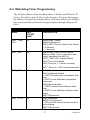
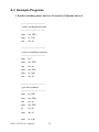
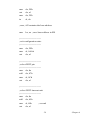
1
IPPC-8151S Series
15" XGA TFT LCD Celeron M
Fanless Industrial Panel PC with
Stainless Steel Chassis
User Manual
Copyright
The documentation and the software included with this product are copyrighted 2009 by Advantech Co., Ltd. All rights are reserved. Advantech
Co., Ltd. reserves the right to make improvements in the products
described in this manual at any time without notice. No part of this manual may be reproduced, copied, translated or transmitted in any form or
by any means without the prior written permission of Advantech Co., Ltd.
Information provided in this manual is intended to be accurate and reliable. However, Advantech Co., Ltd. assumes no responsibility for its use,
nor for any infringements of the rights of third parties, which may result
from its use.
Acknowledgements
Intel and Pentium are trademarks of Intel Corporation.
Microsoft Windows and MS-DOS are registered trademarks of
Microsoft Corp.
All other product names or trademarks are properties of their respective
owners.
Part No. 2003815100
1st Edition
Printed in Taiwan
June 2009
IPPC-8151S User Manual
ii
Product Warranty (2 years)
Advantech warrants to you, the original purchaser, that each of its products will be free from defects in materials and workmanship for two years
from the date of purchase.
This warranty does not apply to any products which have been repaired or
altered by persons other than repair personnel authorized by Advantech,
or which have been subject to misuse, abuse, accident or improper installation. Advantech assumes no liability under the terms of this warranty as
a consequence of such events.
Because of Advantech’s high quality-control standards and rigorous testing, most of our customers never need to use our repair service. If an
Advantech product is defective, it will be repaired or replaced at no
charge during the warranty period. For out-of-warranty repairs, you will
be billed according to the cost of replacement materials, service time and
freight. Please consult your dealer for more details.
If you think you have a defective product, follow these steps:
1.
Collect all the information about the problem encountered. (For
example, CPU speed, Advantech products used, other hardware
and software used, etc.) Note anything abnormal and list any
onscreen messages you get when the problem occurs.
2.
Call your dealer and describe the problem. Please have your manual, product, and any helpful information readily available.
3.
If your product is diagnosed as defective, obtain an RMA (return
merchandize authorization) number from your dealer. This allows
us to process your return more quickly.
4.
Carefully pack the defective product, a fully-completed Repair and
Replacement Order Card and a photocopy proof of purchase date
(such as your sales receipt) in a shippable container. A product
returned without proof of the purchase date is not eligible for warranty service.
5.
Write the RMA number visibly on the outside of the package and
ship it prepaid to your dealer.
iii
Declaration of Conformity
CE
This product has passed the CE test for environmental specifications. Test
conditions for passing included the equipment being operated within an
industrial enclosure. In order to protect the product from being damaged
by ESD (Electrostatic Discharge) and EMI leakage, we strongly recommend the use of CE-compliant industrial enclosure products.
FCC Class A
Note: This equipment has been tested and found to comply with the limits
for a Class A digital device, pursuant to part 15 of the FCC Rules. These
limits are designed to provide reasonable protection against harmful
interference when the equipment is operated in a commercial environment. This equipment generates, uses, and can radiate radio frequency
energy and, if not installed and used in accordance with the instruction
manual, may cause harmful interference to radio communications. Operation of this equipment in a residential area is likely to cause harmful interference in which case the user will be required to correct the interference
at his own expense.
Technical Support and Assistance
Step 1. Visit the Advantech web site at www.advantech.com/support
where you can find the latest information about the product.
Step 2. Contact your distributor, sales representative, or Advantech's customer service center for technical support if you need additional
assistance. Please have the following information ready before
you call:
- Product name and serial number
- Description of your peripheral attachments
- Description of your software (OS, version, software, etc.)
- A complete description of the problem
- The exact wording of any error messages
IPPC-8151S User Manual
iv
Safety Instructions
1.
Read these safety instructions carefully.
2.
Keep this User's Manual for later reference.
3.
Disconnect this equipment from any AC outlet before cleaning.
Use a damp cloth. Do not use liquid or spray detergents for cleaning.
4.
For plug-in equipment, the power outlet socket must be located
near the equipment and must be easily accessible.
5.
Keep this equipment away from humidity.
6.
Put this equipment on a reliable surface during installation. Dropping it or letting it fall may cause damage.
7.
The openings on the enclosure are for air convection. Protect the
equipment from overheating. DO NOT COVER THE OPENINGS.
8.
Make sure the voltage of the power source is correct before connecting the equipment to the power outlet.
9.
Position the power cord so that people cannot step on it. Do not
place anything over the power cord.
10.
All cautions and warnings on the equipment should be noted.
11.
If the equipment is not used for a long time, disconnect it from the
power source to avoid damage by transient overvoltage.
12.
Never pour any liquid into an opening. This may cause fire or electrical shock.
13.
Never open the equipment. For safety reasons, the equipment
should be opened only by qualified service personnel.
14.
If one of the following situations arises, get the equipment checked
by service personnel:
a. The power cord or plug is damaged.
b. Liquid has penetrated into the equipment.
c. The equipment has been exposed to moisture.
d. The equipment does not work well, or you cannot get it to work
according to the user's manual.
e. The equipment has been dropped and damaged.
f. The equipment has obvious signs of breakage.
v
15.
DO NOT LEAVE THIS EQUIPMENT IN AN ENVIRONMENT
WHERE THE STORAGE TEMPERATURE MAY GO BELOW
-40° C OR ABOVE 85° C. THIS COULD DAMAGE THE
EQUIPMENT. THE EQUIPMENT SHOULD BE IN A CONTROLLED ENVIRONMENT.
Safety Precaution - Static Electricity
Follow these simple precautions to protect yourself from harm and the
products from damage.
1.
To avoid electrical shock, always disconnect the power from your
PC chassis before you work on it. Don't touch any components on
the CPU card or other cards while the PC is on.
2.
Disconnect power before making any configuration changes. The
sudden rush of power as you connect a jumper or install a card may
damage sensitive electronic components.
IPPC-8151S User Manual
vi
Contents
Chapter
Chapter
1 General Information ....................................... 2
1.1
1.2
Introduction ....................................................................... 2
Specifications .................................................................... 3
1.3
1.4
I/O View............................................................................ 4
Dimensions........................................................................ 5
Stand Kit............................................................................ 9
VESA Arm Kit .................................................................. 9
Install Panel Mount ......................................................... 10
Installing I/O Cables........................................................ 10
Install a 2.5" SATA HDD ............................................... 10
Installing a PCI Expansion Card ..................................... 11
Installing a Power Connector .......................................... 11
3 I/O Connector & Setting Mode ................... 14
3.1
Chapter
General ........................................................................... 3
LCD Specifications ........................................................ 4
2 System Setup.................................................... 8
2.2
2.3
2.4
2.5
2.6
2.7
2.8
Chapter
1.2.1
1.2.3
IPPC-8151S..................................................................... 14
3.1.1
COM1,COM3,COM4 : Serial port RS232 .................. 17
4 Software Configuration ................................ 20
4.1
4.2
Overview ......................................................................... 20
Utilities and Drivers ........................................................ 20
4.2.1
4.2.2
Touchscreen Gesture Introduction ............................... 22
Touch Gesture Utility .................................................. 22
Appendix A WDT Programming ...................................... 26
A.1
A.2
Overview ......................................................................... 26
Watchdog Timer Programming....................................... 27
A.3
Example Programs .......................................................... 28
Table A.1:Watchdog Runtime Registers ..................... 27
vii
Table of Contents
IPPC-8151S User Manual
viii
CHAPTER
1
General Information
Sections include:
• Introduction
• Specifications
• Dimensions
Chapter 1 General Information
1.1 Introduction
The IPPC-8151S is designed with a fully sealed stainless steel enclosure
and uses a special tapered & food safe rubber seal between the bezel and
the touchscreen. This allows it to satisfy the stringent standards required
in food processing, clinical, chemical or pharmaceutical laboratories. Its
fully enclosed design without ventilation slots and external fans makes its
completely protected against splashed water, achieving a NEMA4 (IP66)
grade of protection.
IP66 Grade Protection
The IP66 rating guarantees waterproof and dustproof protection, ensuring
reliable operation in any hazardous environment. Front model to support
front IP66 protection grade. All-around model supports IP66 protection
grade for all sides including I/O
Anti-corrosive Chassis with Chemical Resistant Touchscreen
Stainless steel chassis' are a great fit for many industrial applications due
to their ability to minimize contamination and maintain strict hygienic
requirements. 316L stainless steel is more resistant to corrosion than 304,
and IP66 protection provides waterproof protection, making them easy to
clean or disinfect even with high pressure water. Furthermore the dustproof capabilities make them exceptionally suitable for applications in
hazardous environments. The FDA Food-Standard Sealing Materials
meet high hygienic requirements and the touchscreen is resistant to chemical, detergents and disinfectants.
High Performance, Fanless Design
IPPC-8151S is equipped with a 15" LCD screen and a bright and sharp
display. The embedded Intel Celeron M 1GHz, 1MB L2 cache and 1GB
DDR2 memory satisfy most application computing needs. The fanless
design extends operation life, with enhanced anti-shock and anti-vibration properties suitable for harsh environments. Furthermore, with one
CompactFlash slot, one PCI expansion and one SATA HDD, IPPC-8151S
provides flexibility and meets high capacity demands.
IPPC-8151S User Manual
2
1.2 Specifications
1.2.1 General
Dimensions (W x H x D):
Front Panel: 400 x 313.6 x 91.24 mm
Control Box: 385.3 x 255.3 x 66/81.2 mm
Cut out Dimensions: 388 x 301.5 mm
Weight: 13 kg (28 lb)
Power Supply: 85W
Input Voltage: 10~30Vdc
Output Voltage: +3.3V@8A,+5V@10A,+12V@4A,[email protected],
-12V@1A
Disk Drive Housing: Supports 1 x 2.5"SATA HDD, 1 x CompactFlash
1.2.2 System Specifications
CPU: Intel Celeron M Yonah 423 1.06GHz w/ 1M L2 cache
BIOS: Award 4MB
North Bridge: 945GME
South Bridge: ICH7M-DH
Memory: SO-DIMM 200pin DDR2 533MHz, Dual Channel, Default
1GB x 1, Up to 4G
Storage: Support 1 x 2.5" SATA and 1 x CF Card Slot (Type II)
Ethernet Ports: 10/100/1000 Base-T x 2 (Realtek RTK8111B)
Serial Ports: RS-232 x 3 (COM1, COM3, COM4)
I/O Ports: VGA x 1, USB2.0 x 4, PS/2 Keyboard x1, PS/2 Mouse x 1,
Mic-in, Line-in, Line-out
PCI Bus Expansion Slot: 1 x PCI expansion slot
Watchdog Timer: Super I/O SMSC,SCH3114, Interval 1sec
3
Chapter 1
1.2.3 LCD Specifications
Backlight Life: 50,000 hrs
Contrast Ratio: 400:1
Display Size: 15"
Display Type: XGA TFT LCD
Luminance: 350 cd/m2
Max. Colors: 262,144
Max. Resolution: 1024 x 768
Viewing Angle (H/V° ): 120/100
1.2.4 Touchscreen Specifications
Lifespan: 10 millions times touch at single point
Light Transmission: >80%
Type: Analog resistive 5-wire
1.2.5 Environmental
Humidity: 5 ~ 85% @ 40° C (non-condensing)
Ingress Protection on Front Panel: NEMA 4X / IP66
Operating Temperature: 0 ~ 50° C (32 ~ 122° F)
Storage Temperature: -20 ~ 60° C (-4 ~ 140° F)
Vibration Protection: 5 ~ 500 Hz, 1Grms random vibration
1.3 I/O View
IPPC-8151S User Manual
4
1.4 Dimensions
110.00 [4.33]
7.35 [0.29]
27.65 [1.09]
232.60 [9.16]
2.00 [0.08]
91.24 [3.59]
66.00 [2.60]
11.00 [0.43]
G
H
J
400.00 [15.75]
385.30 [15.17]
Chapter 1
5
385.30 [15.17]
110.00 [4.33]
313.60 [12.35]
35.00 [1.38]
7.20 [0.28]
255.30 [10.05]
110.00 [4.33]
308.70 [12.15]
110.00 [4.33]
85.00 [3.35]
400.00 [15.75]
19.65 [0.77]
110.00 [4.33]
85.00 [3.35]
110.00 [4.33]
19.65 [0.77]
90.00 [3.54]
85.00 [3.35]
90.00 [3.54]
85.00 [3.35]
7.15 [0.28]
10.40 [0.41]
299.20 [11.78]
311.87 [12.28]
IPPC-8151S User Manual
6
CHAPTER
2
System Setup
Sections include:
• Enclosure Kit
• Desktop Kit
• VESA Arm Kit
• Panel Mounting
• Installing I/O Cables
• Installing a 2.5" SATA HDD
• Installing a PCI Expansion Card
• Installing a Power Connector
Chapter 2 System Setup
2.1 Enclosure Kit
With IPPC-8151S enclosure kit (P/N: IPPC-8151S-EMKE), IPPC-8151S
can provide all-around IP66 waterproof and dustproof protection. Please
follow the instruction below to make sure IP66 protection.
1.
Put IPPC-8151S into the enclosure kit
2.
Use the fixture to make sure IPPC-8151S is closed tightly with the
enclosure kit. Please also use the pad to avoid the scratch on surface while screwing. The surface of the front panel and the enclosure kit should be in the horizon line.
Note: The fixture can be bought from a hardware store.
3.
Use the screws from IPPC-8151S-EMKE accessory kit. The Torpque value is required minimum 10Kgf.
4.
Repeat action 1, 2 and 3 until the four sides of the enclosures kit are
closed tightly with screws.
IPPC-8151S User Manual
8
2.2 Stand Kit
With IPPC-8151S stand kit (P/N: IPPC-8151S-SMKE), IPPC-8151S can
stand on the desk, install on the wall or ceiling to meet the environment
requirement. The stand kit also supports 360 degree C adjustment for the
different view angle. The instruction below shows how to install and use
the stand kit.
1.
Use the screws from the accessory box of the stand kit to fix the
stand kit in both sides.
2.
Use the thumb screw to adjust the different view angle or desk, wall
or ceiling install.
2.3 VESA Arm Kit
IPPC-8151S arm kit (P/N: IPPC-8151S-AMKE) is to help you to control
IPPC-8151S. The instruction below shows how to install arm kit.
1.
Use the screws from the accessory kit of arm kit to fix the arms in
both sides.
9
Chapter 2
2.4 Install Panel Mount
1.
Take the mounting brackets out of IPPC-8151S accessory box.
2.
Attach the four mounting brackets by inserting the screws into the
keyhole slots on the cover of the monitor.
3.
Use the screws to secure the brackets to the cover. Tighten the
screws to secure the monitor to the back panel.
2.5 Installing I/O Cables
Open the cover from the rear and bottom.
Put the cables through the rear hole to the bottom.
Connect the cables through the bottom.
2.6 Install a 2.5" SATA HDD
IPPC-8151S supports one enhanced Serial Advanced Technology Attachment (SATA) hard disk drive to IPPC-8151S. Please use a wide-temperature industrial hard disk to meet the thermal requirement.
1.
Unscrew the back cover and open it.
2.
Remove four screws and take off HDD bracket.
3.
Insert the HDD into the bracket
IPPC-8151S User Manual
10
2.7 Installing a PCI Expansion Card
1.
Unscrew the rear cover and open it.
2.
Remove the the slot bracket.
3.
Insert the add-on card, and close the rear cover
2.8 Installing a Power Connector
1.
Use the tool from the accessory box
2.
Press down to open connector hole and insert power wire
11
Chapter 2
IPPC-8151S User Manual
12
CHAPTER
3
Jumper Settings &
Connectors
Sections include:
• Jumpers Settings
Chapter 3 I/O Connector & Setting Mode
3.1 IPPC-8151S
IPPC-8151S User Manual
14
1
CON. #
Function
Description
CN1
CN2
CN3
DDR2 SO-DIM*2
INVERTER
INVERTER VRCtrl
CN4
CN5
CN6
LVDS
VGA + COM1
LAN1 + USB*2
Up to 4GB
TDK TBD266LR-1
Control inverter brightness by Digital VR
DS1804
Dual channels LVDS
VGA + Full DB9 Serial Port COM1
CN7
LAN2 + USB*2
CN8
CN9
CN10
CN11
CN12
CN13
CN14
CN15
CN16
USB
USB
AUDIO
BUZZER SELECT
CPU FAN
FWH
PS/2 KB + MS
TOUCH PANEL
IDE
CN17
COM3 + COM4
10/100/1000MB Ethernet LAN1 + USB*2
10/100/1000MB Ethernet LAN2 + USB*2
Inside USB port 1
Inside USB port 2
Line-out / Line-in / MIC by ALC650
Select internal or external buzzer
CPU fan, work @ 12V
BIOS FWH, Flash P/N 46LF004B
PS/2 keyboard & mouse
8-wired touch panel sensor signals
Secondary IDE, Internal IDE
44pin(2mm) connector
Full DB9 Serial Port COM3 & COM4
15
Chapter 3
CN18
BOOT Ctrl
CN19
SNMP I2C BUS
CN20
CN21
SA1
SA2
JP1
BUZZER OUTPUT
ATX Power-input
SATA1
SATA2
LVDS PWR Select
JP2
CLEAR CMOS
JP3
BATTERY Verify
JP4
LVDS PANEL Sel.
Receive external push-button signal /
reset / HDDLED
I2C bus for SNMP measure, WINBOND
W83782G
External buzzer output, depend on CN11
Standard ATX Power input
Primary IDE, Master
Primary IDE, Slave
For 5V Panel: 1-2 (default) , For 3.3V
panel: 2-3
Normal: open (default) , Clear CMOS:
short
Normal: 1-2 (default) , just for battery
current measure
1024 * 768 24bit
1280 * 1024 48bit
(Default)
800 * 600 24bit
VGA only
IPPC-8151S User Manual
16
1600*1200 48bit
3.1.1 COM1,COM3,COM4 : Serial port RS232
Connector Definitions
1
6
5
9
Pin
Signal
1
NDCD
2
NRX
3
NTX
4
NDTR
5
GND
6
NDSR
7
NRTS
8
NCTS
9
NRI
17
Chapter 3
IPPC-8151S User Manual
18
CHAPTER
4
Intel Chipset
Sections include:
• Overview
• Utilities and Drivers
• Dual Display Setting
• Touchscreen Installation &
Configuration
Chapter 4 Software Configuration
4.1 Overview
In IPPC-8151S , Advantech provides a CD-ROM with utilities and drivers included. Please install the Chipset INF driver, VGA graphics driver,
LAN driver, audio driver , Touch Screen driver , Watchdog Timer (WDT)
driver sequentially.
4.2 Utilities and Drivers
The following utilities and drivers are provided with IPPC-8151S. You
can also find out the updated description of the utilities and drivers in the
ReadMe.txt file on the CD-ROM.
Intel Chipset Software Installation Utility
Path: \INF\
Available for the OS’s below,
• Microsoft Windows 2000
• Microsoft Windows XP
VGA Drivers (Intel Graphics Driver)
Path: \VGA\
Available for the OS’s below,
• Microsoft Windows 2000
• Microsoft Windows XP
Intel Network Driver
Path: \Lan\
Available for the OS’s below,
• Microsoft Windows 2000
• Microsoft Windows XP
IPPC-8151S User Manual
20
Audio Driver
Path: \ audio\
Available for the OS’s below,
• Microsoft Windows 2000
• Microsoft Windows XP
Touchscreen Driver
Path: \Touchscreen Driver\DMC 9000 (Combo)
Available for the OS’s below,
• Microsoft Windows 2000
• Microsoft Windows XP and more, on the driver CD-ROM.
WatchDog Timer Driver
Path: \WDT\
Available for the OS’s below:
• Microsoft Windows 2000
• Microsoft Windows XP
21
Chapter 4
4.2.1 Touchscreen Gesture Introduction
Through the touchscreen gesture, the system can disable/enable touch
screen functionality, execute hotkeys, execute applications or power on/
off the system. Please refer to 4.2.2 for more details.
4.2.2 Touch Gesture Utility
Enabling Touch Gesture:
There are two ways to enable touch gesture utility. One is to click PM
icon in right side of task bar and select gesture enable. Two is to go to
PenMount control panel and click gesture enable button.
IPPC-8151S User Manual
22
Touch Gesture Utility Setup
Please go to PenMount control panel and click gesture setting button.
A. Enable / Disable Touch Gesture
B. Gesture Sensing Time
The time is to complete one gesture. Value can be set from 200ms to
2500ms.
C. Gesture Setting
The setting for the individual gesture. The blue color means the gesture
has been enabled. The gray color means the gesture has been disabled.
D. Disable the individual gesture
E. Hotkey Setting
When the gesture is detected, system will receive the hot key value by the
setting.
F. Application Setting
When the gesture is detected, system will execute the application by the
setting.
G. Action Setting
When the gesture is detected, system will take action by the setting.
23
Chapter 4
Gesture Default Setting
Page Up
Zoom In
([Pad] +)
Page Down
Zoom Out
([Pad] -)
Backward
(Left Arrow)
Rotate Counter
Clockwised
(Ctrl + L)
Forward
(Right Arrow)
Rotate Clockwised
(Ctrl + K)
Copy
(Ctrl + C)
Open On-Screen
Keyboard
Paste
(Ctrl + V)
Save Document
(Ctrl + S)
Undo
(Ctrl + Z)
Close Program
(Alt + F4)
Delete
IPPC-8151S User Manual
24
A
APPENDIX
2
Watchdog Timer
Programming
Appendix A WDT Programming
A.1 Overview
The IPPC-8151S cards’ watchdog timer can be used to monitor system
software operation and take corrective action if the software fails to function after the programmed period. This section describes the operation of
the watchdog timer, and how to program it.
The watchdog timer is built into the super I/O controller
SMSC SCH3114. It provides the following functions for user programming:
• Can be enabled and disabled by user's program.
• Timer can be set from 1 to 255 seconds or 1 to 255 minutes.
• Generates an interrupt or resets signal if the software fails to reset the
timer after time-out.
IPPC-8151S User Manual
26
A.2 Watchdog Timer Programming
The I/O port address of the watchdog timer is 2E(hex) and 2F(hex), 2E
(hex) is the address port. 2F(hex) is the data port. You must first assign
the address of register by writing address value into address port 2E(hex),
then write/read data to/from the assigned register through data port 2F
(hex).
Table A.1: Watchdog Runtime Registers
Name
REG
OFFSET
(HEX)
DESCRIPTION
WDT_TIME_
OUT
65
Watch-dog Timeout
Bits[6:0] Reserved
Bit[7] WDT Time-out Value Units Select
= 0 Minutes
= 1 Seconds
WDT_VAL
66
Watch-dog Timer Time-out Value
Binary coded, units = minutes or seconds, selectable via Bit[7] of
WDT_TIME_OUT register (0x65).
0x00 Time out disabled
0x01 Time-out = 1 minute (second)
…..
0xFF Time-out = 255 minutes (seconds)
WDT_CFG
67
Bit[0] Reserved
Bit[1] Keyboard Enable
=1 WDT is reset upon a Keyboard interrupt.
=0 WDT is not affected by Keyboard
interrupts.
Bit[2] Mouse Enable
=1 WDT is reset upon a Mouse interrupt.
=0 WDT is not affected by Mouse interrupts.
Bit[7:3] Reserved
WDT_CTRL
68
Bit[1] Reserved
Bit[2] Force Timeout,
=1 Forces WD timeout event; this bit is
self-clearing
Bit[7:3] Reserved
27
Chapter A
A.3 Example Programs
1. Enable watchdog timer and set 10 seconds of timeout interval
;---------------------------; enter configuration state
;---------------------------mov
dx, 2Eh
mov
al, 55h
out
dx, al
;---------------------------; select watchdog registers
;---------------------------mov
al, 7
mov
dx, 2Eh
out
dx, al
mov
dx, 2Fh
mov
al, 0ah
out
dx, al
;---------------------------; get base address
;---------------------------mov
al, 60h
mov
dx, 2Eh
out
dx, al
mov
dx, 2Fh
in
al, dx
mov
ah, al
mov
al, 61h
IPPC-8151S User Manual
28
mov
dx, 2Eh
out
dx, al
mov
dx, 2Fh
in
al, dx
; now, AX contains the base address
mov
bx, ax ; save base address in BX
;---------------------------; exit configuration state
;---------------------------mov
dx, 2Eh
mov
al, 0AAh
out
dx, al
;---------------------------; select WDT pin
;---------------------------mov
dx, bx
add
dx, 47h
mov
al, 0Ch
out
dx, al
;---------------------------; select WDT timeout unit
;---------------------------mov
dx, bx
add
dx, 65h
mov
al, 80h
out
dx, al
; second
29
Chapter A
;---------------------------; select WDT timeout value
;---------------------------mov
dx, bx
add
dx, 66h
mov
al, 10
out
dx, al
; 10 seconds
2. Enable watchdog timer and set 5 minutes of timeout interval
;---------------------------; enter configuration state
;---------------------------mov
dx, 2Eh
mov
al, 55h
out
dx, al
;---------------------------; select watchdog registers
;---------------------------mov
al, 7
mov
dx, 2Eh
out
dx, al
mov
dx, 2Fh
mov
al, 0ah
out
dx, al
;---------------------------; get base address
;---------------------------mov
al, 60h
IPPC-8151S User Manual
30
mov
dx, 2Eh
out
dx, al
mov
dx, 2Fh
in
al, dx
mov
ah, al
mov
al, 61h
mov
dx, 2Eh
out
dx, al
mov
dx, 2Fh
in
al, dx
; now, AX contains the base address
mov
bx, ax ; save base address in BX
;---------------------------; exit configuration state
;---------------------------mov
dx, 2Eh
mov
al, 0AAh
out
dx, al
;---------------------------; select WDT pin
;---------------------------mov
dx, bx
add
dx, 47h
mov
al, 0Ch
out
dx, al
31
Chapter A
;---------------------------; select WDT timeout unit
;---------------------------mov
dx, bx
add
dx, 65h
mov
al, 00h
out
dx, al
; minute
;---------------------------; select WDT timeout value
;---------------------------mov
dx, bx
add
dx, 66h
mov
al, 5
out
dx, al
; 5 minutes
3. Enable watchdog timer to be reset upon mouse interrupt
(Note: WDT timeout value must be set before this function can work)
;---------------------------; enter configuration state
;---------------------------mov
dx, 2Eh
mov
al, 55h
out
dx, al
;---------------------------; select watchdog registers
;---------------------------mov
al, 7
mov
dx, 2Eh
IPPC-8151S User Manual
32
out
dx, al
mov
dx, 2Fh
mov
al, 0ah
out
dx, al
;---------------------------; get base address
;---------------------------mov
al, 60h
mov
dx, 2Eh
out
dx, al
mov
dx, 2Fh
in
al, dx
shl
al, 8
mov
al, 61h
mov
dx, 2Eh
out
dx, al
mov
dx, 2Fh
in
al, dx
; now, AX contains the base address
mov
bx, ax ; save base address in BX
;---------------------------; exit configuration state
;---------------------------mov
dx, 2Eh
mov
al, 0AAh
out
dx, al
33
Chapter A
;---------------------------; select WDT configuration
;---------------------------mov
dx, bx
add
dx, 67h
in
al, dx
or
al, 04h
out
dx, al
; reset upon mouse interrupt
4. Enable watchdog timer to be reset upon keyboard interrupt
(Note: WDT timeout value must be set before this function can work)
;---------------------------; enter configuration state
;---------------------------mov
dx, 2Eh
mov
al, 55h
out
dx, al
;---------------------------; select watchdog registers
;---------------------------mov
al, 7
mov
dx, 2Eh
out
dx, al
mov
dx, 2Fh
mov
al, 0ah
out
dx, al
;---------------------------; get base address
IPPC-8151S User Manual
34
;---------------------------mov
al, 60h
mov
dx, 2Eh
out
dx, al
mov
dx, 2Fh
in
al, dx
shl
al, 8
mov
al, 61h
mov
dx, 2Eh
out
dx, al
mov
dx, 2Fh
in
al, dx
; now, AX contains the base address
mov
bx, ax ; save base address in BX
;---------------------------; exit configuration state
;---------------------------mov
dx, 2Eh
mov
al, 0AAh
out
dx, al
;---------------------------; select WDT configuration
;---------------------------mov
dx, bx
add
dx, 67h
in
al, dx
35
Chapter A
or
al, 02h
out
dx, al
; reset upon keyboard interrupt
5. Force timeout
(Note: WDT timeout value must be set before this function can work)
;---------------------------; enter configuration state
;---------------------------mov
dx, 2Eh
mov
al, 55h
out
dx, al
;---------------------------; select watchdog registers
;---------------------------mov
al, 7
mov
dx, 2Eh
out
dx, al
mov
dx, 2Fh
mov
al, 0ah
out
dx, al
;---------------------------; get base address
;---------------------------mov
al, 60h
mov
dx, 2Eh
out
dx, al
mov
dx, 2Fh
in
al, dx
IPPC-8151S User Manual
36
shl
al, 8
mov
al, 61h
mov
dx, 2Eh
out
dx, al
mov
dx, 2Fh
in
al, dx
; now, AX contains the base address
mov
bx, ax ; save base address in BX
;---------------------------; exit configuration state
;---------------------------mov
dx, 2Eh
mov
al, 0AAh
out
dx, al
;---------------------------; Force timeout
;---------------------------mov
dx, bx
add
dx, 68h
in
al, dx
or
al, 04h
out
dx, al
; force timeout
37
Chapter A
IPPC-8151S User Manual
38