1
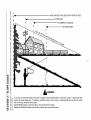
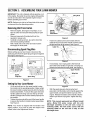
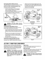
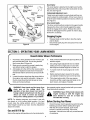
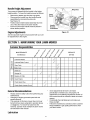
OPERATOR'S
MANUAL
22" Self-Propelled
Mower
Model Series
520 Thru 530
IMPORTANT:
READ SAFETY RULES AND INSTRUCTIONS
CAREFULLY
Warning:
This unit is equipped with an internal combustion engine and should not be used on or near any unimproved forest*
covered, brush-covered or grass-covered land unless the engine's exhaust system is equipped with a spark arrester meeting
applicable local or state laws (if any). If a spark arrester is used, it should be maintained in effective working order by the operator.
In the State of Califorffla the above is required by law (Section 4442 of the California Public Resources Code). Other states may have
similar laws. Federal laws apply on federal lands. A spark arrester for the muffler is available through your nearest engine authorized
service dealer or contact the service department, P.O. Box 361131 Cleveland, Ohio 44136-0019.
MTD LLC, P.O. BOX 361131 CLEVELAND,
PRINTED IN U.S.A.
OHIO 44136-0019
FORM NO. 770-10349B
(11/01)
TABLEOFCONTENTS
Content
Page
Maintaining Safety .............................................................................................
3
Slope Gauge ......................................................................................................
6
Assembling Your Lawn Mower ...........................................................................
7
Know Your Lawn Mower ....................................................................................
8
Operating Your Lawn Mower .............................................................................
9
Making Adjustments ..........................................................................................
10
Maintaining Your Lawn Mower ...........................................................................
11
Storing Your Lawn Mower ..................................................................................
13
Troubleshooting
14
.................................................................................................
Parts List ............................................................................................................
16
FINDINGMODELNUMBER
This Operator's Manual is an important part of your new lawn mower. It wilt help you assemble, prepare and
maintain the unit for best performance. Please read and understand what it says.
¢
Before you start assembling your new equipment, please locate the model plate on the
equipment and copy the information from it in the space provided below. The information on
the model plate is very important if you need help from our Customer Support Department or
an authorized dealer.
You can locate the model number by looking down at the rear of the deck. A sample model plate is
explained below. For future reference, please copy the model number and the serial number of the
equipment in the space below.
Copy the model number here:
ENGINEINFORMATION
The engine manufacturer is responsible for all engine-related issues with regards to performance, powerrating, specifications, warranty and service. Please refer to the engine manufacturer's Owner's/Operator's
Manual packed separately with your unit for more information.
CALLINGCUSTOMER
SUPPORT
If you have difficulty assembling this product or have any questions regarding the controls, operation or
maintenance of this unit, please call the Customer Support Department.
Call 1- (330) 220-4MTD (4683) or 1- (800)-800-7310 to reach a Customer Support
representative. Please have your unit's model number and serial number ready when you
call. See previous section to locate this information. You will be asked to enter the serial
number in order to process your call.
SECTION1: IMPORTANT
SAFEOPERATION
PRACTICES
WARNING:
This symbol points out important safety instructions which, if not followed, could
endanger the personal safety and/or property of yourself and others. Read and follow all instructions in
this manual before attempting to operate this machine. Failure to comply with these instructions may
result in personal injury. When you see this symbol - heed its warning.
WARNING:
Engine Exhaust,
some of its constituents,
and certain vehicle
components contain or emit chemicals known to State of California
and birth defects or other reproductive harm.
to cause cancer
DANGER:
This machine was built to be operated according to the rules for safe operation in this
manual. As with any type of power equipment, carelessness or error on the part of the operator can
result in serious injury. This machine is capable of amputating hands and feet and throwing objects.
Failure to observe the following safety instructions could result in serious injury or death.
8.
GeneralOperation
1.
2.
3.
4.
5.
6.
7.
Read this operator's manual carefully in its entirety
before attempting to assemble this machine. Read,
understand, and follow all instructions on the machine
and in the manual(s) before operation. Be completely
familiar with the controls and the proper use of this
machine before operating it. Keep this manual in a safe
place for future and regular reference and for ordering
replacement parts.
This machine is a precision piece of power equipment,
not a plaything. Therefore, exercise extreme caution at all
times. Your unit has been designed to perform one job: to
mow grass. Do not use it for any other purpose.
Never allow children under 14 years old to operate this
machine. Children 14 years old and over should read and
understand the operation instructions and safety rules in
this manual and should be trained and supervised by a
parent. Only responsible individuals who are familiar with
these rules of safe operation should be allowed to use
this machine.
Thoroughly inspect the area where the equipment is to
be used. Remove all stones, sticks, wire, bones, toys and
other foreign objects which could be tripped over or
picked up and thrown by the blade. Thrown objects can
cause serious personal injury. Plan your mowing pattern
to avoid discharge of material toward roads, sidewalks,
bystanders and the like. Also, avoid discharging material
against a wall or obstruction which may cause
discharged material to ricochet back toward the operator.
To help avoid blade contact or a thrown object injury, stay
in the operator zone behind the handles and keep
children, bystanders, helpers and pets at least 75 feet
from the mower while it is in operation. Stop machine if
anyone enters the area.
Always wear safety glasses or safety goggles during
operation and while performing an adjustment or repair to
protect your eyes. Thrown objects which ricochet can
cause serious injury to the eyes.
Wear sturdy, rough-soled work shoes and close-fitting
slacks and shirts. Shirts and pants that cover the arms
and legs and steel-toed shoes are recommended. Never
operate this machine in bare feet, sandals, slippery or
light weight (e.g. canvas) shoes.
9.
10.
11.
12.
13.
14.
15.
16.
17.
18.
19.
3
Do not put hands or feet near rotating parts or under the
cutting deck. Contact with the blade can amputate hands
and feet.
A missing or damaged discharge cover can cause blade
contact or thrown object injuries.
Many injuries occur as a result of the mower being pulled
over the foot during a fall caused by slipping or tripping.
Do not hold on to the mower if you are falling; release the
handle immediately.
Never pull the mower back toward you while you are
walking. If you must back the mower away from a wall or
obstruction first look down and behind to avoid tripping
and then follow these steps:
a. Step back from the mower to fully extend your
arms.
b. Be sure you are well balanced with sure footing.
c. Pull the mower back slowly, no more than half way
toward you.
d. Repeat these steps as needed.
Do not operate the mower while under the influence of
alcohol or drugs.
Do not engage the self-propelled mechanism on units so
equipped while starting engine.
The blade control handle is asafetydevice.
Never
attempt to bypass its operation. Doing so makes the
safety device inoperative and may result in personal
injury through contact with the rotating blade. The blade
control handle must operate easily in both directions and
automatically return to the disengaged position when
released.
Never operate the mower in wet grass. Always be sure of
your footing. A slip and fall can cause serious personal
injury. If you feel you are losing your footing, release the
blade control handle immediately and the blade will stop
rotating within three seconds.
Mow only in daylight or in good artificial light. Walk, never
run.
Stop the blade when crossing gravel drives, walks or
roads.
If the equipment should start to vibrate abnormally, stop
the engine and check immediately for the cause.
Vibration is generally a warning of trouble.
Shut the engine off and wait until the blade comes to a
complete
stopbefore
removing
thegrasscatcher
or
unclogging
thechute.Thecutting
bladecontinues
to
rotate
forafewseconds
aftertheengine
isshutoff.Never
placeanypartofthebodyinthebladeareauntilyouare
surethebladehasstopped
rotating.
20. Neveroperate
mowerwithout
proper
trailshield,
discharge
cover,grasscatcher,
bladecontrol
handle
or
othersafety
protective
devices
inplaceandworking.
Never
operate
mower
withdamaged
safetydevices.
Failure
todoso,canresultinpersonal
injury.
21. Muffler
andengine
become
hotandcancause
aburn.Do
nottouch.
22. Only use parts and accessories made for this machine by
the manufacturer. Failure to do so, can result in personal
injury.
23. If situations occur which are not covered in this manual,
use care and good judgment. Contact your dealer for
assistance. Telephone 1-800-800-7310 for the name of
your nearest dealer.
SlopeOperation
Slopes are a major factor related to slip and fall accidents
which can result in severe injury. Operation on slopes
requires extra caution. If you feel uneasy on a slope, do not
mow it. For your safety, use the slope gauge included as part
of this manual to measure slopes before operating this unit on
a sloped or hilly area. If the slope is greater than 15 degrees,
do not mow it.
Do:
1.
2.
3.
5.
6.
Service
Safe Handling Of Gasoline:
1.
2.
3.
4.
5.
6.
Mow across the face of slopes; never up and down.
Exercise extreme caution when changing direction on
slopes.
Watch for holes, ruts, rocks, hidden objects, or bumps
which can cause you to slip or trip. Tall grass can hide
obstacles.
Always be sure of your footing. A slip and fall can cause
serious personal injury. If you feel you are losing your
balance, release the blade control handle immediately,
and the blade will stop rotating within 3 seconds.
7.
8.
9.
10.
DONot:
1.
2.
3.
Do not mow near drop-offs, ditches or embankments, you
could lose your footing or balance.
Do not mow slopes greater than 15 degrees as shown on
the slope gauge.
Do not mow on wet grass. Unstable footing could cause
slipping.
doorways, shrubs, trees, or other objects that may
obscure your vision of a child who may run into the
mower.
Keep children away from hot or running engines. They
can suffer burns from a hot muffler.
Never allow children under 14 years old to operate a
power mower. Children 14 years old and over should
read and understand the operation instructions and
safety rules in this manual and should be trained and
supervised by a parent.
11.
12.
13.
Children
14.
To avoid personal injury or property damage use extreme
care in handling gasoline. Gasoline is extremely
flammable and the vapors are explosive. Serious
personal injury can occur when gasoline is spilled on
yourself or your clothes which can ignite.
Wash your skin and change clothes immediately.
Use only an approved gasoline container.
Never fill containers inside a vehicle or on a truck or
trailer bed with a plastic liner. Always place containers on
the ground away from your vehicle before filling.
When practical, remove gas-powered equipment from
the truck or trailer and refuel it on the ground. If this is not
possible, then refuel such equipment on a trailer with a
portable container, rather than from a gasoline dispenser
nozzle,
Keep the nozzle in contact with the rim of the fuel tank or
container opening at all times until fueling is complete. Do
not use a nozzle lock-open device.
Extinguish all cigarettes, cigars, pipes and other sources
of ignition.
Never fuel machine indoors because flammable vapors
will accumulate in the area.
Never remove gas cap or add fuel while the engine is hot
or running. Allow engine to cool at least two minutes
before refueling.
Never over fill fuel tank. Fill tank to no more than ½ inch
below bottom of filler neck to provide space for fuel
expansion.
Replace gasoline cap and tighten securely.
ff gasoline is spilled, wipe itoff the engine and equipment.
Move unit to another area. Wait 5 minutes before starting
the engine.
Never store the machine or fuel container inside where
there is an open flame, spark or pilot light as on a water
heater, space heater, furnace ,clothes dryer or other gas
appliances.
To reduce fire hazard, keep mower freeof grass, leaves,
or other debris build-up. Clean up oil or fuel spillage and
remove any fuel soaked debris.
Allow a mower to cool at least 5 minutes before storing.
Tragic accidents can occur if the operator is not alert to the
presence of children. Children are often attracted to the
mower and the mowing activity. They do not understand the
dangers. Never assume that children will remain where you
last saw them.
General Service:
1.
1.
2.
3.
4.
Keep children out of the mowing area and under the
watchful care of a responsible adult other than the
operator.
Be alert and turn mower off if a child enters the area.
Before and while moving backwards, look behind and
down for small children.
Use extreme care when approaching blind corners,
15.
2.
Never run an engine indoors or in a poorly ventilated
area. Engine exhaust contains carbon monoxide, an
odorless and deadly gas.
Before cleaning, repairing, or inspecting, make certain
the blade and all moving parts have stopped. Disconnect
the spark plug wire and ground against the engine to
prevent unintended starting.
3. Check
thebladeandengine
mounting
boltsatfrequent
intervals
forproper
tightness.
Also,visually
inspect
blade
fordamage
(e.g.,bent,cracked,
worn)Replace
blade
withtheoriginal
equipment
manufacture's
(O.EM.)blade
only,listedinthismanual.
"Useofpartswhichdonot
meettheoriginal
equipment
specifications
mayleadto
improper
performance
andcompromise
safety!"
4. Mowerblades
aresharpandcancut.Wrapthebladeor
weargloves,
anduseextracaution
whenservicing
them.
5. Keepallnuts,bolts,andscrews
tighttobesurethe
equipment
isinsafeworking
condition.
6. Never
tamper
withsafety
devices.
Check
theirproper
operation
regulady.
7. Afterstriking
aforeign
object,
stoptheengine,
disconnect
thesparkplugwireandground
against
theengine.
Thoroughly
inspect
themower
foranydamage.
Repair
thedamage
before
starting
andoperating
themower.
8. Never
attempt
tomakeawheelorcutting
height
adjustment
whiletheengine
isrunning.
9. Grass
catcher
components,
discharge
cover,
andtrail
shieldaresubject
towearanddamage
whichcould
expose
moving
partsorallowobjects
tobethrown.
For
safetyprotection,
frequently
checkcomponents
and
replace
immediately
withoriginal
equipment
manufacturer's
(O.EM.)partsonly,listedinthismanual.
"Useofpartswhichdonotmeettheoriginal
equipment
specifications
mayleadtoimproper
performance
and
compromise
safety!"
10. Donotchange
theengine
governor
setting
oroverspeed
theengine.
Thegovernor
controls
themaximum
safe
operating
speed
oftheengine.
11. Maintain
orreplace
safety
andinstruction
labels,
as
necessary.
12. Observe
proper
disposal
lawsandregulations.
Improper
disposal
offluidsandmaterials
canharmthe
environment.
understand
the warnings
and instructions in Restrict
this manual
and ofonthis
the power
machine.
WARNINGand -follow
YOUR
RESPONSIBILITY:
the use
machine to persons who read,
NOTE: Not all safety labels shown may apply to yeurlawn mower.
H
SIGHT AND HOLD THIS LEVEL WITH A VERTICAL TREE
1"9
c
H
A POWER POLE
A CORNER OF A BUILDING
O
OR A FENCE POST
oJ
o
c
o
I
co
u}
O
c
co
E
_D
I
O
J_
H
u}
C_
15 °
._.
Z
co
"&
u}
WARNING
co .
Do not mow on inclines with a slope in excess of 15 degrees (a rise of approximately 2=1/2 feet every 10 feet). A riding mower could
_ O
co
c_
overturn and cause serious injury. If operating a walk=behind mower on such a slope, it is extremely difficult to maintain your footing
and you could slip, resulting in serious injury.
o. -_
_
Operate RIDING mowers up and down slopes, never across the face of slopes.
Operate WALK-BEHIND mowers across the face of slopes, never up and down slopes.
SECTION3: ASSEMBLING
YOURLAWNMOWER
IMPORTANT: This unit is shipped without gasoline or oil
in the engine. Be certain to service engine with gasoline
and oil as instructed in the separate engine manual
before operating your mower.
NOTE: Reference to right or left hand side of the mower
is observed from the operating position.
Nuts
Lower
Handle
RemovingUnitFromCarton
Remove staples, break glue on top flaps, or cut
tape at carton end and peel along top flap to open
carton.
Remove loose parts if included with unit (i.e.,
operator's manual, etc.)
Carefully cut along corners, lay carton down flat,
and remove packing material.
Roll or slide unit out of carton and check carton
thoroughly for loose parts.
Handle
Bracket
Assemblies
Figure 2
Fasten the cables to the lower handle with the
cable tie found on the lower handle. Pull the cable
tie tight and trim offthe excess. See Figure 3.
Cable Tie
Disconnecting
SparkPlugWire
Before setting up your lawn mower, disconnect the
spark plug wire from the spark plug and ground against
the engine. See Figure 1.
Handle
Figure 3
If not already, move rope guide to the first hole
above the lower handle on right side. The wing nut
loosens and secures the rope guide. See Figure 4.
Starter\
Rope
\
_
Upper Handle
jWing
Nut
Spark _
Plug Wire
Figure 1
Rope j_
Guide
, Lower
Handle
SettingUpYourLawnMower
Lift up and pull back on the upper handle to raise
the handle intothe operating position. Make certain
the lower handle is seated securely into the handle
bracket assemblies. To secure the upper and lower
handle, tighten the wing nuts near the top of lower
handle (carriage bolts must be seated properly into
the handle).
Tighten the wing nuts at the end of the lower handle
to secure the handle to handle bracket assemblies.
See Figure 2.
NOTE: Your mower is shipped with the handle in the
higher position. If you wish to lower the height of the
handle, refer to the Adjustment Section.
Figure 4
With the spark plug wire disconnected and
grounded, hold the blade control handle against the
upper handle, and pull the starter rope out of the
engine. Release the blade control handle. Slip the
starter rope into the rope guide. Tighten the wing
nut.
NOTE: This manual represents two different model
series. Model 520 series comes with the side
discharge assembly on the unit and a snap on
mulching baffle. The 530 series comes with the
mulching baffle on the unit and a snap on side
discharge chute.
RemovingChute Retainer (Models 520 Series)
The chute deflector on your mower is held in an upright
position by a retainer for shipping purposes only.
Remove the retainer, following steps below, before
running the mower for the first time.
Slide the hooks of the side discharge chute under
the hinge pin on the mulching baffle. Make sure that
the hooks snaps into place, locking the chute firmly
onto the mower. See Figure 7.
Release the mulching baffle.
Push the chute deflector up and towards the
engine. Holding the deflector in this position,
remove the retainer. See Figure 5.
Lower the chute deflector carefully to its operating
position keeping your fingers out of the way.
Discharge
fChute
Raise Chute
Deflector
Retainer
Baffle
Hook
Insert Notches
on Top of Lip
Figure 5
Figure
removed and discarded before operating
WARNING: The chute retainer must be
the mower.
6
Mulching
Baffle
InstallingMulchingBaffle (Model 520 Series)
If your mower is equipped with the optional mulching
baffle, install it following these instructions:
Lift up side discharge chute and insert the mulching
baffle so that the notches at the bottom of the baffle
sit firmly on the lip of the deck opening. See Figure
6.
Snap the hooks of the baffle over the hinge pin on
the discharge chute. Make sure that the hooks
snaps into place, locking the mulching baffle firmly
on to the mower.
Release the side discharge chute.
Installing Side DischargeChute (Model 530 Series)
If your mower is equipped with the optional side
discharge chute, install it following these instructions:
Hinge Pin
Side Discharge
Chute
Hooks
Figure 7
SECTION4: KNOWYOURLAWNMOWER
Read this operator's manual and safety rules before
operating your lawn mower. Compare the illustration in
Figure 8 with your lawn mower to familiarize yourself
with the location of various controls and adjustments.
Save this manual for future reference.
WARNING: The operation of any lawn
mower can result in foreign objects being
thrown into the eyes, which can damage
your eyes severely. Always wear safety
glasses while operating the mower, or
while performing any adjustments
or
repairs on it.
EngineControls
See the separate engine manual for the location and
function of the controls on the engine.
Blade Control Handle
The blade control handle is located on the upper handle
of the mower. The blade control handle must be
depressed in order to operate the unit. Release blade
control handle to stop engine and blade.
is a safety device. Never attempt to bypass
WARNING: This blade control mechanism
its operations.
RecoilStarter
e Control
Handle
_-Drive
Control
#_
Handle
Mulching
Plug
jDischarge
,F Chute
Starter
Cutting Height
Adjustment
Lever
Mulchi_
Plug
Discharge
Chute
The recoil starter is attached to the right lower handle.
Stand behind the unit and pull the recoil starter to start
the unit. See Figure 8.
CuttingHeight AdjustmentLevers
These levers are located on each wheel and they are
used to adjust the cutting height. All four levers have to
be at the same relative position to ensure a uniform cut.
See Figure 8.
Drive ControlHandle
The drive control handle is located on the upper handle.
Squeeze the drive control handle against the upper
handle to engage drive system. Release the control
handle to disengage the drive system in order to stop,
slow down, or backup.
Stopping
Engine
Release blade control handle to stop the engine
and the blade.
j
Figure
Disconnect spark plug wire and ground it to a bolt
on the engine.
8
SECTION5: OPERATING
YOURLAWNMOWER
v
TowardsBetterMowerPerformance
1.
2.
3.
4.
Pour fresh, clean gasoline into the mower's gas
tank until the tank is full. Do not use gasoline
that is more than 30 days old.
Make sure to connect the mower's spark plug
wire before trying to start the engine.
Add engine oil to the oil fill on the mower engine.
Check the dipstick and add more if necessary.
Remember that the oil level has to touch the fill
line.
Locate the primer decal near the primer bulb on
the engine, and read its instruction. Using your
thumb, press the primer bulb slowly as many
times as the decal advises.
5.
Hold control handle down and pull rope firmly to
start the engine.
6.
Set cutting height adjustment lever to middle
setting and mow a single pass on your lawn;
then adjust to desired height for a closer cut.
7.
To mulch insert the mulch plug/cover
mower.
8.
Before storing the lawn mower for the winter,
use stabilizer-treated fuel and run the tank dry.
9.
Thirty days before start of the new season,
check the air filter, spark plug and blade on the
lawn mower, and replace if needed.
on the
J
&
WARNING: Keep hands and feet away from
chute area on the cutting deck. The
operation of any lawn mower can result in
foreign objects being thrown into the eyes,
which can result in severe eye damage.
Always wear safety glasses or eye shields.
NOTE: For shipping purposes your mower is set with
the wheels in a low cutting height position. For best
results raise the cutting position until it is determine
which height is best for your lawn. See the Adjustment
Section for details.
GasandOilFill-Up
Service the engine with gasoline and oil as instructed in
the separate engine manual packed with your mower.
Read instructions carefully.
WARNING: Never fill fuel tank indoors with
engine running or until the engine has
been allowed to cool for at least two
minutes after running.
BeforeStartingYourMower
Check for proper clutch operation by performing the
following procedure before starting the engine.
With the drive clutch released, push mower
forward. It should move freely. Pull mower
backward. It should move with only a small amount
of resistance.
Ifthewheelstendtolockup,theclutchmaynotbe
releasingcompletely.
Donotstarttheengineuntil
corrections
havebeenmade.
Checkthedrivecableforseverebends,kinks,or
binding.Alsocheckforgrassbuild-uparoundthe
belt.
Ifdriveclutchcontrolneedsadjustment
seethe
Adjustment
Section.
For best results, do not cut wet grass because it tends
to stick to the underside of the mower, preventing
proper discharge of grass clippings, and could cause
you to slip and fall. New grass, thick grass, orwet grass
may require a narrower cut.
For a healthier lawn, never cut off more than one-third
of the total length of the grass. Your lawn should be cut
in the fall as long as there is growth. This mower is
designed to be operated at full throttle to give you the
best cut and do the most effective job of mowing or
mulching.
Starting Engine
Attach spark plug wire to spark plug. Make certain
the metal cap on the end of the spark plug is
fastened securely over the metal tip on the spark
plug.
Prime engine as instructed in the separate engine
manual packed with your unit.
Your lawn mower may be equipped with a constant
speed throttle, which is set at full throttle for best
performance.
Stand behind the mower and squeeze the blade
control handle against the upper handle.
Grasp recoil starter handle and pull rope out slowly
until engine reaches the start of compression cycle
(rope will pull slightly harder at this point). Let the
rope rewind slowly. Pull rope with a rapid,
continuous, full arm stroke. Keeping a firm grip on
the starter handle, let the rope return to the starter
slowly.
WARNING: If you strike a foreign object,
stop the engine. Remove wire from the
spark plug, thoroughly inspect the mower
for any damage, and repair the damage
before restarting
and operating
the
mower. Extensive vibration of the mower
during operation
is an indication of
damage. The unit should be promptly
inspected and repaired.
Mulching
For effective mulching, do not cut wet grass because it
tends to stick to the underside of the deck, preventing
proper mulching of grass clippings. New or thick grass
may require a narrower cut. The ground speed should
be adjusted to the condition of the lawn. If mowing has
been delayed and the grass has been allowed to grow
in excess of 4", mulching is not recommended. Mow
using the side discharge to reduce the grass height to 3
1/4" maximum before mulching.
UsingYourLawnMower
Be sure that the lawn is clear of stones, sticks, wire, or
other objects which could damage the lawn mower or
the engine. Such objects could be accidently thrown by
the mower in any direction and cause serious personal
injury to the operator and others.
SECTION6: MAKINGADJUSTMENTS
adjustments
without
engine
WARNING: Do
not atfirst
any stopping
time make
any
and disconnecting spark plug wire.
CuttingHeightAdjustment
Each wheel has a height adjustment lever which
provides cutting height adjustment. When the
adjustment lever is moved from one location to another
the height of cut will be changed. Simply depress the
lever towards wheel and move lever assembly to
desired position. See Figure 9.
Height
\_
Adjustment Levers_
IMPORTANT: All wheels must be placed in the same
relative position. For rough or uneven lawns, move the
height adjustment lever to a higher position. This wilt
help stop scalping of the grass.
_//
Figure 9
10
HandleHeightAdjustment
Nuts
Your mower is shipped with the handle in the higher
height position. To lower the height proceed as follows:
Lower'
Handle
Remove the starter rope from the rope guide,
Disconnect the handle from the handle bracket
assemblies by removing the wing nuts.
See Figure 10.
Position each handle bracket assembly stud into
one of the other holes in the lower handle.
Handle
Bracket
Each end of the lower handle must be placed in
same relative position.
EngineAdjustments
Figure 10
See the separate engine manual packed with your unit
for adjustments to the engine.
SECTION7: MAINTAINING
YOURLAWNMOWER
CustomerResponsibilities
MAINTENANCE
SCHEDULE
o,_
_
£
_
£
_
,o_
_
.co
°
_
no<
SERVICE
DATES
Lubricate Wheels
t0
Lubricate Blade Control
:::3
_
Clean Deck
n
Blade Care
Check Oil
Change Oil
Replace Air Filter
_
Clean Engine
UA
Check Spark Plug
Check Spark Arrester (if any)
GeneralRecommendations
Some adjustments will have to be made
periodically to maintain your unit properly. All
adjustments in the Making Adjustments section of
this manual should be checked at least once each
season.
Periodically check all fasteners and make sure
these are tight.
Follow the maintenance schedule under Customer
Always observe safety rules when performing any
maintenance.
Changing of engine governed speed will void
engine warranty.
The warranty on this lawn mower does not cover
items that have been subjected to operator abuse
or negligence. To receive full value from the
warranty, operator must maintain the lawn mower
as instructed in this manual.
Responsibilities to get quality performance from
your lawn mower.
Lubrication
11
serviced. To service the air cleaner, refer to the
separate engine manual packed with your unit.
The spark plug should be cleaned and the gap
reset once a season. Spark plug replacement is
recommended at the start of each mowing season.
disconnect
spark
plug
WARNING:
Always
stop wire
engine before
and
cleaning, lubricating or doing any kind of
service work on the lawn mower.
Blade Control Handle and Drive Clutch Control:
Clean the engine regularly with a cloth or brush. Keep
the cooling system (blower housing area) clean to
permit proper air circulation which is essential to engine
performance and life. Be certain to remove all grass,
dirt, and combustible debris from muffler area.
Lubricate the pivot points on the blade control handle
and the drive clutch control at least once a season with
light oil. These handles must operate freely in both
directions. See Figure 11.
Wheels: Lubricate the wheels at least once a season
Deck
The underside of the mower deck should be cleaned
with light oil (or motor oil). If the wheels are removed for
any reason, lubricate the surface of the axle bolt and
inner surface of the wheel with light oil.
after each use to prevent a buildup of grass clippings,
leaves, dirt, or other matter. If this debris is allowed to
accumulate, it will invite rust and corrosion, and may
prevent proper mulching, discharge, or bagging. The
deck may be cleaned by tilting the mower and scraping
clean with a suitable tool (make certain the spark plug
wire is disconnected).
Chute Deflector or Mulching Baffle: Lubricate the
torsion spring and pivot point periodically with light oil to
prevent any rust or binding.
Engine: Follow the separate engine manual packed
with you unit for lubrication instructions.
iMPORTANT:We do not recommend the use of a
pressure washer or garden hose to clean your unit.
Cutting Blade Removal,Replacement,and Sharpening
When removing the cutting blade for sharpening or
replacement, protect your hands with a pair of
heavy gloves or use a heavy rag to hold the blade.
Remove the bolt and the blade bell support which
hold the blade and the blade adapter to the engine
crankshaft. See Figure 12.
Remove the blade and the adapter from the
crankshaft.
Lubricate
Blade
LubricateJ
J
Adapte_
I
Blade Bell
_Support
Figure 11
Maintenance
f Hex Bolt
NOTE: When tipping the unit or emptying the fuel tank
keep the air cleaner side of engine up. Never tip the
mower more than 90 degrees and do not leave the
mower tipped for any length of time. Oil can drain into
the upper part of the engine causing a starting problem.
Figure 12
adapter
for cracks,
especially
WARNING:
Periodically
inspectif you
the strike
blade
a foreign object. Replace when necessary.
Engine
Refer to the separate engine manual for all engine
maintenance instructions.
When sharpening the blade, follow the original angle of
grind as a guide. It is extremely important that each
cutting edge receives an equal amount of grinding to
prevent an unbalanced blade. An unbalanced blade will
cause excessive vibration when rotating at high
speeds. It may cause damage to the mower, and could
break causing personal injury.
Maintain engine oil as instructed in the separate
engine manual packed with your unit.
Service air cleaner every 25 hours under normal
conditions. Poor engine performance and flooding
usually indicate that the air cleaner should be
12
Pull the belt from under the deck toward rear of unit
The blade can be tested by balancing it on a round
shaft screwdriver. Remove metal from the heavy side
until it balances evenly. It is recommended that the
blade always be removed from the adapter when
testing for balance. Before reinstalling the blade and
the blade adapter to the unit, lubricate the engine
crankshaft and the inner surface of the blade adapter
with light oit.
and through gap in cutting deck.
Transmission
Pulley
Be sure to install the blade with end tips facing up
or the side of the blade marked "Bottom" (or with
part number) facing the ground when the mower is
in the operating position.
Slide the blade adapter onto the engine crankshaft.
Place the blade on the adapter. Be certain the
blade is aligned and seated on the blade adapter
flanges.
Place blade bell support on blade. Make sure the
notches on the blade belt support are aligned with
small holes in the blade.
Belt_
Belt
Keeper
Figure 14
If belt can not be removed by slipping belt around
blade, then remove the blade following the steps in
the previous section. See Figure 15.
Slide new belt around engine pulley and through
gap in cutting deck.
Pull belt toward front of mower and around
transmission pulley.
Make sure belt is routed inside the belt keepers.
See Figure 14.
Reattach the transmission cover using the rivets
previously removed.
Reassemble blade and torque as instructed in
previous section.
Replace hex bolt and tighten hex bolt to torque: 450
in. lbs. min., 600 in. lbs. max.
NOTE: To ensure safe operation of your mower, the
blade bolt must be checked periodically for correct
torque.
Drive Belt RemovalAnd Replacement
Disconnect the spark plug wire and ground it
against the engine.
Drain the fuel tank or place a piece of plastic
beneath the cap to prevent gasoline leakage.
If unit is tipped for easier access to belt, tip the
mower back on its side with the air filter side away
from the ground.
(
Transmission
Cover
Keeper Bracket
_
Figure 15
Rivet
Figure 13
0ff-SeasonStorage
To get easier access to the belt, just securely place
the mower on raised blocks.
The following steps should be taken to prepare your
lawn mower for storage.
Remove the transmission cover by sliding off the
two plastic rivets with a screwdriver on each side of
cover. See Figure 13.
With the drive system in the disengaged position,
the belt can be lifted offthe transmission pulley.
See Figure 14.
Clean and lubricate mower thoroughly as described
in the lubrication instructions.
IMPORTANT:We do not recommend the use of a
pressure washer or garden hose to clean your unit.
13
Refertoenginemanualforcorrectenginestorage
instructions.
Coatmower'scuttingbladewithchassisgreaseto
preventrusting.
Storemowerina dry,cleanarea.Donotstorenext
tocorrosivematerials,
suchasfertilizer.
NOTE:When
storing any type of power equipment in a
poorly ventilated or metal storage shed, care should be
taken to rust-preof the equipment. Using a light oil or
silicone, coat the equipment, especially cables and all
moving parts.
SECTION8: TROUBLESHOOTING
Problem
Engine fails to start
Engine runs erratic
Engine overheats
Idles poorly
Excessive vibration
Cause
1.
2.
3.
4.
Blade control handle disengaged.
Spark plug wire disconnected.
Fuel tank empty or stale fuel.
Blocked fuel line.
5.
6.
Faulty spark plug.
Engine flooded
2.
3.
4.
5.
6.
1.
2.
Spark plug wire loose.
Blocked fuel line or stale fuel.
2.
3.
4.
5.
6.
Vent in gas plugged.
Water or dirt in fuel system.
Dirty air cleaner.
Carburetor out of adjustment.
3.
1.
2.
Engine oil level tow.
Air flow restricted.
3.
Carburetor not adjusted properly.
1.
2.
3.
Fill crankcase with proper oil.
Remove blower housing and clean.
Adjust carburetor.
1.
Spark plug fouled, faulty or gap too
wide.
1.
2.
3.
Carburetor improperly adjusted.
Dirty air cleaner.
2.
3.
Reset gap to .030" or replace spark
plug.
Adjust carburetor.
Clean air cleaner.
1.
Cutting blade loose or unbalanced.
1.
Tighten blade and adapter. Balance
blade.
2.
Bent cutting blade.
2.
Replace blade.
Wet grass.
1.
Do not mow when grass is wet; wait
until later to cut.
2.
Excessively high grass.
2.
3.
Dull blade.
3.
Mow once at a high cutting height, then
mow again at desired height or make a
narrower cutting path.
Sharpen or replace blade.
1.
Wheels not positioned correctly.
1.
2.
Dull blade.
2.
1.
Belt not installed properly.
1.
2.
Debris clogging drive operation.
2.
Mowerwilt not mulch gras,_ 1.
Uneven cut
Wheels will not propel
Remedy
1.
1.
4.
5.
6.
Engage blade control handle.
Connect wire to spark plug.
Fill tank with clean, fresh gasoline.
Clean fuel line.
Clean, adjust gap, or replace.
Wait a few minutes to restart, but do not
prime.
Connect and tighten spark plug wire.
Clean fuel line; fill tank with clean, fresh
gasoline
Clear vent.
Drain fuel tank. Refill with fresh fuel.
Clean air cleaner.
Adjust carburetor.
Place all four wheels in same height
position.
Sharpen or replace blade.
Check belt for proper pulley installation
and movement.
Clean out debris.
NOTE: For repairs beyond the minor adjustments listed above, contact your nearest authorized service dealer.
14
NOTES
15
ModelSeries520 thru 530
1
9
2
7
5
,
6
13
12
_-,._14
11
10
47
18
32
72j
47_
49
72
50
I
58
"_
4
57
4.!,
16
ModelSeries520 thru 530
Ref.
No.
Part No.
Ref.
No.
Part Description
1,
747-1214
Drive Control Handle
2,
747-1161A
3,
746-1113
Part No.
Part Description
38.
731-0073
Blade Control Handle
39.
756-1183
Drive Pulley
Blade Control Cable - B&S
40.
748-0426
746-1132
Blade Control Cable - B&S
41.
742-0642A
Blade Adapter
Blade 22"
4,
746-1114
746-1092A
Blade Control Cable- Tec
Drive Control Cable
42.
742-0742A
736-0452
Mulching Blade 22"
Bell Washer .396 ID x 1.140 OD
5,
749-1092A
6,
710-1205
Upper Handle
Eye Bolt
43.
44.
710-1044
782-0584
Hex Cap Screw 3/8-24 x 1,5
Forward Height Adjustment Plate - RH
7,
726.0279
712-0324
Wing Nut 1/4-20
Hex Lock Nut 1/4-20
45.
46.
741-0710
716.0216
Sleeve Bearing
8,
9,
710-0606
Hex Cap Screw 1/4-20x 1.5
47.
720-0426
Adjustment Knob
10.
710-1174
682-0544
682-0545
Spring Lever Assembly - LH (FWD)
736-0451
Carriage Bolt 5/16-18 x 2.0
Shoulder Washer ,320 ID x .93 OD
48.
11.
12.
13.
726.0284
749-1093B
Wing Nut
Lower Handle
49.
50.
731-2522
715-0221
14.
725-0157
Cable Tie
51.
717-1761
15.
782-9065
16.
73%2280
Hinge Clip
Trail Shield
52.
717-1762
736-0105
17.
710-0896
Hex Screw 1/4-14 x ,625
53.
634-0190
18.
682-3062A
19.
736-3050
Handle Bracket Assembly - RH
Flat Washer .406 ID x .812 OD
54.
55.
738-1168
747-0710
20.
21.
712-0431
Lock Nut 3/8-16
56.
732-1014
Torsion Spring
682-3063A
682-0096
Handle Bracket Assembly- LH
57.
63%0098
Mulching Baffle (If Equipped)
Deck Assembly 22"
58.
731-1034B
682-0110
59.
60.
61.
736-0270
73%1035B
716.0216
Side Discharge Assembly
Bell Washer .265 ID x .75 OD
22.
Transmission
Cover
Hex Cap Screw 3/8-16 x ,75
Spring Lever Assembly - RH (FWD)
Wheel Dust Cover
Pin
Spur Gear 14T - LH
Spur Gear 14T - RH
Bell Washer .401 ID x .870 OD
Front Wheel Assembly 8 x 1.8
Shoulder Screw 3/8
Hinge Pin
23.
782-9063
24.
710-0654A
Deck Assembly 22" (No Sprigs)
Engine Belt Keeper Bracket
Hex Washer Screw 3/8-16 x 1,0
25.
712-0240
Jam Nut 7/16-20
62.
741-0717
Thrust Bearing ,688 ID x 1,938 OD
26.
736-0407
Bell Washer .45 ID x 1.00 OD
63.
732-0984B
Spring Lever
27.
756-1167
28.
754-0483
Pulley
V-Belt
64.
65.
682-0093
738-1127
Rear Pivot Arm Assembly
Shoulder Screw 3/8-16
29.
30.
710-1276
782-9062
Hex Washer Screw 1/4-20 x ,750
66.
736-0182
Spring Washer
Transmission
67.
734-1864
Rear Wheel Assembly 14 x 1.8
31.
732-0992
32.
782-0585
728-0199
68.
69.
70.
731-2230
731-1386D
748-0390
Snap Discharge Chute (If Equipped)
Snap Mulching Plug (If Equipped)
33.
Compression Spring
Forward Height Adjustment Plate - LH
Rivet
34.
750-1209
Sleeve Spacer .550 ID x 2,5
71.
716-0865
Snap Ring .500
35.
716-0198
Retainer Ring
72.
736-0105
36.
618-0391A
Transmission Assembly
73.
712-0130
Washer Spacer .401 ID x ,870 OD
Hex Lock Nut 3/8-16
37.
750-1210
Sleeve Spacer .550 ID x 8,9
Belt Keeper Bracket
17
Chute Hinge
Hex Cap Screw 3/8-16 x .75
Bearing Spacer
ModelSeries520 thru530
©
6
2
3
7.
13
_9
15
Ref.
No.
1.
618-0392
2.
721-0329
Upper Housing Assembly
Oil Seal .500 ID x .687 OD
3.
4.
741-0673
736-0520
Flange Bearing .503 ID x .689 OD
Flat Washer .504 ID x .700 OD x ,030
736-0711
Flat Washer 504 ID x .700 OD x .035
736-0712
Flat Washer 504 ID x .700 OD x .040
736-0713
Flat Washer .504 ID x .700 OD x .045
5.
717-1596
6.
715-0139
Bevel Gear 44T
Roll Pin
711-1595
8.
9.
719-0538
710-1276
Output Shaft
Lower Housing
Hex Washer Screw 1/4-20 x .75
10.
11.
716-0231
736-0336
E-Ring .750
Flat Washer .625 ID x 1.00D x ,030
736-0337
736-0349
Flat Washer ,625 ID x 1.00D
736-0494
Flat Washer .63 ID x 1.00D x .020
Flat Washer ,632 ID x 1.00D x .035
736-0495
741-0735
Flat Washer .632 ID x 1.00D
12.
13.
719-0537
14.
736-0336
Upper Housing
Flat Washer .625 ID x 1.00D x .030
736-0494
Flat Washer .632 ID x 1.00D
711-1390
Input Shaft
15.
x .035
Needle Bearing .625 x .813
18
x .035
19
MANUFACTURER'S
LIMITED WARRANTY
The limited warranty set forth below is given by MTD LLC
with respect to new merchandise purchased and used in the
d.
United States, its possessions and territories.
MTD LLC warrants this product against defects for a period of
FOR:
MTD LLC does not extend any warranty for products
sold or exported outside of the United States, its possessions and territories, except those sold through MTD
LLC's authorized channels of export distribution.
e.
Parts that are not genuine MTD parts are not covered by
this warranty.
Service completed by someone other than an authorized
two (2) years commencing on the date of original purchase
and will, at its option, repair or replace, free of charge, any
part found to be defective in materials or workmanship. This
f.
limited warranty shall only apply if this product has been
operated and maintained in accordance with the Operator's
g.
Manual furnished with the product, and has not been subject
to misuse, abuse, commercial use, neglect, accident,
improper maintenance, alteration, vandalism, theft, fire,
No implied warranty, including any implied warranty of
water, or damage because of other peril or natural disaster.
Damage resulting from the installation or use of any acces-
applies after the applicable period of express written
warranty above as to the parts as identified. No other
sory or attachment not approved by MTD LLC for use with the
product(s) covered by this manual will void your warranty as
to any resulting damage.
express warranty, whether written or oral, except as
Normal wear parts or components thereof are subject to separate terms as follows: All normal wear parts or component
failures will be covered on the product for a period of 90 days
regardless of cause. After 90 days, but within the two year
period, normal wear part failures will be covered ONLY IF
caused by defects in materials or workmanship of OTHER
component parts. Normal wear parts and components
include, but are not limited to: batteries, belts, blades, blade
adapters, grass bags, rider deck wheels, seats, snow thrower
service dealer is not covered by this warranty.
Transportation charges and service calls are not
covered.
merchantability
of fitness
for a particular purpose,
mentioned above, given by any person or entity, includ*
ing a dealer or retailer, with respect to any product, shall
bind MTD LLC. During the period of the warranty, the
exclusive remedy is repair or replacement of the product
as set forth above.
The provisions as set forth in this warranty provide the
sole and exclusive remedy arising from the sale. MTD
LLC shall not be liable for incidental or consequential
loss or damage including, without limitation, expenses
incurred for substitute or replacement lawn care ser*
skid shoes, shave plates, auger spiral rubber, tires.
vices or for rental expenses to temporarily
ranted product.
HOW TO OBTAIN SERVICE: Warranty service is available,
WITH PROOF OF PURCHASE, through your local autho-
Some states do not allow the exclusion or limitation of inci-
rized service dealer. To locate the dealer in your area, check
your Yellow Pages, or contact MTD LLC at RO. Box 361131,
Cleveland, Ohio 44136-0019, 1-800-800-7310, 1-330-2204683 or log on to our Web site at www.mtdproducts.com.
replace a war*
dental or consequential damages, or limitations on how long
an implied warranty lasts, so the above exclusions or limitations may not apply to you.
In no event shall recovery of any kind be greater than the
amount of the purchase price of the product sold. Alteration
This limited warranty does not provide coverage in the following cases:
a. The engine or component parts thereof. These items
carry a separate manufacturer's warranty. Refer to the
applicable manufacturer's warranty for terms and conditions.
b.
c.
Log splitter pumps, valves, and cylinders have a separate one year warranty.
Routine maintenance items such as lubricants, filters,
blade sharpening, tune-ups, brake adjustments, clutch
adjustments, deck adjustments, and normal deterioration
of the exterior finish due to use or exposure.
MTD LLC, P.O. BOX 361131 CLEVELAND,
of safety features of the product shall void this warranty.
You assume the risk and liability for loss, damage, or injury to
you and your property and/or to others and their property
arising out of the misuse or inability to use the product.
This limited warranty shall not extend to anyone other than
the original purchaser or to the person for whom it was purchased as a gift.
HOW STATE LAW RELATES TO THiS WARRANTY:
This
limited warranty gives you specific legal rights, and you
may also have other rights which vary from state to
state.
OHIO 44136-0019
1-800-800-7310