1
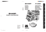
XV-Z10E
XV-Z10E
PROJECTOR
PROJEKTOR
PROJECTEUR
PROJEKTOR
PROYECTOR
PROIETTORE
PROJECTOR
OPERATION MANUAL
BEDIENUNGSANLEITUNG
MODE D’EMPLOI
BRUKSANVISNING
MANUAL DE MANEJO
MANUALE DI ISTRUZIONI
GEBRUIKSAANWIJZING
SHARP CORPORATION
Printed on 100% post-consumer recycled paper.
Gedruckt auf 100% wiederverwertungs Papier.
Imprimé sur 100% de papier recyclé.
Utskrift på återvunnet papper av 100% återvunnet material.
Impreso en 100% de papel reciclado de postconsumo.
Stampato su carta riciclata al 100%.
Gedrukt op 100% kringlooppapier.
XV_Z10E_E_Hyo1_4.p65
1
Printed in Japan
In Japan gedruckt
Imprimé au Japon
Triykt i Japan
Impreso en Japón
Stampato in Giappone
Gedrukt in Japan
TINS-B021WJZZ
03P11-JWM
1
03.12.2, 4:56 PM
ENGLISH .............
-1 –
-68
DEUTSCH ............
-1 –
-68
FRANÇAIS ...........
-1 –
-68
SVENSKA ............
-1 –
-68
ESPAÑOL ............
-1 –
-68
ITALIANO .............
-1 –
-68
NEDERLANDS ....
-1 –
-68
This equipment complies with the requirements of Directive 89/336/EEC and 73/23/EEC as amended
by 93/68/EEC.
Dieses Gerät entspricht den Anforderungen der EG-Richtlinien 89/336/EWG und 73/23/EWG mit
Änderung 93/68/EWG.
Ce matériel répond aux exigences contenues dans les directives 89/336/CEE et 73/23/CEE modifiées
par la directive 93/68/CEE.
Dit apparaat voldoet aan de eisen van de richtlijnen 89/336/EEG en 73/23/EEG, gewijzigd door 93/68/
EEG.
Dette udstyr overholder kravene i direktiv nr. 89/336/EEC og 73/23/EEC med tillæg nr. 93/68/EEC.
Quest’ apparecchio è conforme ai requisiti delle direttive 89/336/EEC e 73/23/EEC come emendata
dalla direttiva 93/68/EEC.
Η εγκατάσταση αυτή ανταποκρίνεται στις απαιτήσεις των οδηγιών της Ευρωπαϊκής Ενωσης 89/
336/ΕΟΚ και 73/23/ΕΟΚ, #πως οι κανονισµοί αυτοί συµπληρώθηκαν απ# την οδηγία 93/68/ΕΟΚ.
Este equipamento obedece às exigências das directivas 89/336/CEE e 73/23/CEE, na sua versão
corrigida pela directiva 93/68/CEE.
Este aparato satisface las exigencias de las Directivas 89/336/CEE y 73/23/CEE, modificadas por
medio de la 93/68/CEE.
Denna utrustning uppfyller kraven enligt riktlinjerna 89/336/EEC och 73/23/EEC så som kompletteras
av 93/68/EEC.
Dette produktet oppfyller betingelsene i direktivene 89/336/EEC og 73/23/EEC i endringen 93/68/EEC.
Tämä laite täyttää direktiivien 89/336/EEC ja 73/23/EEC vaatimukset, joita on muutettu direktiivillä 93/
68/EEC.
SPECIAL NOTE FOR USERS IN THE U.K.
The mains lead of this product is fitted with a non-rewireable (moulded) plug incorporating a 5A fuse.
Should the fuse need to be replaced, a BSI or ASTA approved BS 1362 fuse marked
or
and of
the same rating as above, which is also indicated on the pin face of the plug, must be used.
Always refit the fuse cover after replacing the fuse. Never use the plug without the fuse cover fitted.
In the unlikely event of the socket outlet in your home not being compatible with the plug supplied, cut
off the mains plug and fit an appropriate type.
ASA
DANGER
The fuse from the cut-off plug should be removed and the cut-off plug destroyed immediately and
disposed of in a safe manner.
Under no circumstances should the cut-off plug be inserted elsewhere into a 5A socket outlet, as a
serious electric shock may occur.
To fit an appropriate plug to the mains lead, follow the instructions below:
WARNING:
THIS APPARATUS MUST BE EARTHED.
IMPORTANT:
The wires in this mains lead are coloured in accordance with the following code:
Green-and-yellow
: Earth
Blue
: Neutral
Brown
: Live
As the colours of the wires in the mains lead of this apparatus may not correspond with the coloured
markings identifying the terminals in your plug proceed as follows:
• The wire which is coloured green-and-yellow must be connected to the terminal in the plug which is
or coloured green or green-and-yellow.
marked by the letter E or by the safety earth symbol
• The wire which is coloured blue must be connected to the terminal which is marked with the letter N
or coloured black.
• The wire which is coloured brown must be connected to the terminal which is marked with the letter L
or coloured red.
IF YOU HAVE ANY DOUBT, CONSULT A QUALIFIED ELECTRICIAN.
XV_Z10E_E_pi.p65
1
03.11.7, 4:50 PM
Before using the projector, please read this operation manual carefully.
Introduction
Introduction
ENGLISH
IMPORTANT
For your assistance in reporting the loss or theft of your
Projector, please record the Serial Number located on
the bottom of the projector and retain this information.
Before recycling the packaging, please be sure that
you have checked the contents of the carton thoroughly
against the list of “Supplied accessories” on page 14.
WARNING:
Model No.: XV-Z10E
Serial No.:
Intense light source. Do not look into the beam or view it directly. Be especially careful that children
do not look directly into the beam.
WARNING: To reduce the risk of fire or electric shock, do not expose this product to
rain or moisture.
CAUTION:
To reduce the risk of electric shock, do not remove cabinet. No user-serviceable parts are inside.
Refer servicing to qualified service personnel.
WARNING:
The cooling fan in this projector continues to run for about 90 seconds after the projector enters the standby mode.
During normal operation, when putting the projector into the standby mode always use the STANDBY button on the
projector or on the remote control. Ensure the cooling fan has stopped before disconnecting the power cord.
DURING NORMAL OPERATION, NEVER TURN THE PROJECTOR OFF BY DISCONNECTING THE POWER CORD.
FAILURE TO OBSERVE THIS WILL RESULT IN PREMATURE LAMP FAILURE.
-1
XV_Z10E_E_p01_07.p65
1
03.11.7, 4:13 PM
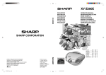
Caution Concerning the Lamp Replacement
There is potential glass particles hazard if the lamp ruptures.
LAMP REPLACEMENT CAUTION
BEFORE REMOVING THE SCREW, DISCONNECT POWER
CORD. HOT SURFACE INSIDE. ALLOW 1 HOUR TO COOL
BEFORE REPLACING THE LAMP. REPLACE WITH SAME
SHARP LAMP UNIT TYPE BQC-PGB10S//1 ONLY.
UV RADIATION : CAN CAUSE EYE DAMAGE. TURN OFF
LAMP BEFORE SERVICING.
HIGH PRESSURE LAMP : RISK OF EXPLOSION. POTENTIAL
HAZARD OF GLASS PARTICLES IF LAMP HAS RUPTURED.
HANDLE WITH CARE. SEE OPERATION MANUAL.
PRECAUTIONS A OBSERVER LORS
DU REMPLACEMENT DE LA LAMPE.
DEBRANCHER LE CORDON D’ALIMENTATION AVANT DE
RETIRER LA VIS. L’INTERIEUR DU BOITIER ETANT
EXTREMEMENT CHAUD, ATTENDRE 1 HEURE AVANT DE
PROCEDER AU REMPLACEMENT DE LA LAMPE.
NE REMPLACER QUE PAR UNE LAMPE SHARP DE TYPE
BQC-PGB10S//1.
RAYONS ULTRAVIOLETS : PEUVENT ENDOMMAGER LES
YEUX. ETEINDRE LA LAMPE AVANT DE PROCEDER
A L’ENTRETIEN.
LAMPE A HAUTE PRESSION : RISQUE D’EXPLOSION.
DANGER POTENTIEL DE PARTICULES DE VERRE EN CAS
D’ECLATEMENT DE LA LAMPE. A MANIPULER AVEC
PRECAUTION, SE REPORTER AU MODE D’EMPLOI.
-2
XV_Z10E_E_p01_07.p65
2
03.11.7, 4:13 PM
How to Read this Operation Manual
Introduction
In this operation manual, the illustration and the screen display are simplified for explanation,
and may differ slightly from actual display.
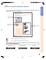
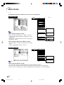
Using the Menu Screen
The menu screens allow you to adjust the image and various projector settings. (The menu items differ
depending on the input mode.)
The menu can be operated with the projector or with the remote control.
On-screen
display
', ", \, | buttons
Menu Selections
ENTER button
(Adjustments)
Button used in
this step
1
Press
.
Note
MENU button
• The “Picture” menu screen for the selected input mode is displayed.
Buttons used in this
operation
ENTER
button
UNDO
button
MENU button
', ", \, |
buttons
-36
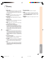
Info ........Indicates safeguards when using the projector.
Note ........Indicates additional information on setup and operation.
For Future Reference
Maintenance
Troubleshooting
Page 60
Glossary
Pages 63 and 64
Page 67
-3
XV_Z10E_E_p01_07.p65
3
03.11.7, 4:13 PM
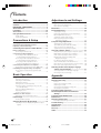
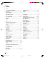
Contents
Introduction
Adjustments and Settings
How to Read this Operation Manual ....................... 3
Contents ................................................................... 4
IMPORTANT SAFEGUARDS .................................... 5
Quick Reference ....................................................... 8
Part Names ............................................................. 10
Accessories ............................................................ 14
Using the Remote Control ..................................... 15
Using the Menu Screen ......................................... 36
Usable Range ............................................................... 15
Inserting the Batteries ................................................... 15
Connections & Setup
Setting up the Screen ............................................ 16
Screen Size and Projection Distance ....................... 17
Projecting a Reversed Image ................................... 18
Connecting the Projector to Other Devices ........ 19
Before Connecting ................................................... 19
Connecting the Power Cord .......................................... 20
Connecting to Video Equipment ............................... 21
Connecting to Video Equipment with an
S-video Output Terminal (INPUT 2) ........................... 21
Connecting to Video Equipment without an
S-video Output Terminal (INPUT 3) ........................... 21
Connecting to Video Equipment with a
Component Output Terminal (INPUT 1) .................... 22
Connecting the Projector to a Computer .................. 24
Connecting to a Computer Using the RGB Cable ........ 24
Controlling the Projector Using a Computer ............ 25
Connecting to a Computer Using an RS-232C
Cable ......................................................................... 25
Menu Selections (Adjustments) .................................... 36
Menu Selection (Settings) ............................................. 38
Menu Items ............................................................. 40
Picture Adjustment ................................................ 42
Adjusting the Image ...................................................... 42
CLR Temp (Adjusting the Colour Temperature) ............ 43
Gamma (Gamma Correction) ....................................... 43
Signal Type (Signal Type Setting) ................................. 44
Memory (Storing and Selecting the
Adjustment Settings) ................................................. 44
Computer Image Adjustment ................................ 45
Adjusting the Computer Image ..................................... 45
Special Modes (Special Mode Settings) ....................... 45
Auto Sync (Auto Sync Adjustment) ............................... 46
Signal Info (Checking the Input Signal) ........................ 46
Using the “Options” Menu .................................... 47
Lamp Timer (Life) (Checking the Lamp Life Status) ..... 47
OSD Display (Setting On-screen Display) .................... 47
Video System (Setting the Video System) ..................... 48
Background (Selecting a Startup and
Background Image) .................................................. 48
Eco Mode (Setting the Eco Mode) ................................ 49
Auto Power Off (Auto Power Off Function) .................... 49
Menu Position (Selecting the Menu Screen Position) ... 50
Menu Color (Selecting the Menu Colour) ...................... 50
Selecting the On-screen Display Language
and the Projection Mode ................................. 51
Selecting the On-screen Display Language ................. 51
Reversing the Projected Image .................................... 51
Basic Operation
Appendix
Image Projection .................................................... 26
Maintenance Indicators ......................................... 52
Replacing the Lamp ............................................... 54
Truning the Projector on ................................................ 26
Switching the INPUT Mode ........................................... 27
Adjusting the Volume .................................................... 27
Turning off the Sound Temporarily ................................ 28
Turning the Power off (Putting the Projector into
the Standby Mode) ................................................... 28
Correcting Trapezoidal Distortion ................................. 29
Adjusting the Lens ........................................................ 30
Using the Adjustment Feet ............................................ 31
Variable Lens Shift Feature ...................................... 32
Adjusting the Projected Image Position ........................ 33
Freeze Image .......................................................... 33
Freezing a Moving Image ............................................. 33
Lamp ............................................................................. 54
Caution Concerning the Lamp ...................................... 54
Replacing the Lamp ...................................................... 54
Removing and Installing the Lamp Unit ........................ 55
Resetting the Lamp Timer ............................................. 56
Connecting Pin Assignments ............................... 57
RS-232C Specifications and Command
Settings ............................................................. 58
Computer Compatibility Chart .............................. 59
Maintenance ........................................................... 60
Replacing the Air Filter .......................................... 61
Selecting the Picture Display Mode ..................... 34
Cleaning and Replacing the Air Filter ........................... 61
Switching the Picture Display Using Different Input
Signals ...................................................................... 34
Troubleshooting ..................................................... 63
Specifications ......................................................... 65
Dimensions ............................................................. 66
Glossary .................................................................. 67
Index ........................................................................ 68
-4
XV_Z10E_E_p01_07.p65
4
03.11.7, 4:38 PM
IMPORTANT SAFEGUARDS
Introduction
CAUTION: Please read all of these instructions before you operate this product and save these
instructions for later use.
Electrical energy can perform many useful functions. This product has been engineered and manufactured to
assure your personal safety. BUT IMPROPER USE CAN RESULT IN POTENTIAL ELECTRICAL SHOCK OR
FIRE HAZARDS. In order not to defeat the safeguards incorporated in this product, observe the following basic
rules for its installation, use and servicing.
1. Read Instructions
13. Power-Cord Protection
All the safety and operating instructions should be read before
the product is operated.
2. Retain Instructions
The safety and operating instructions should be retained for
future reference.
3. Heed Warnings
All warnings on the product and in the operating instructions
should be adhered to.
4. Follow Instructions
All operating and use instructions should be followed.
5. Cleaning
Unplug this product from the wall outlet before cleaning. Do
not use liquid cleaners or aerosol cleaners. Use a damp cloth
for cleaning.
6. Attachments
Do not use attachments not recommended by the product
manufacturer as they may cause hazards.
7. Water and Moisture
Do not use this product near water–for example, near a bath
tub, wash bowl, kitchen sink, or laundry tub; in a wet
basement; or near a swimming pool; and the like.
8. Accessories
Do not place this product on an unstable cart, stand, tripod,
bracket, or table. The product may fall, causing serious injury
to a child or adult, and serious damage to the product. Use
only with a cart, stand, tripod, bracket, or table recommended
by the manufacturer, or sold with the product. Any mounting
of the product should follow the manufacturer’s instructions,
and should use a mounting accessory recommended by the
manufacturer.
9. Transportation
A product and cart combination should
be moved with care. Quick stops,
excessive force, and uneven surfaces
may cause the product and cart
combination to overturn.
10. Ventilation
Slots and openings in the cabinet are provided for ventilation
to ensure reliable operation of the product and to protect it
from overheating, and these openings must not be blocked
or covered. The openings should never be blocked by placing
the product on a bed, sofa, rug, or other similar surface. This
product should not be placed in a built-in installation such as
a bookcase or rack unless proper ventilation is provided or
the manufacturer’s instructions have been adhered to.
11. Power Sources
This product should be operated only from the type of power
source indicated on the marking label. If you are not sure of
the type of power supply to your home, consult your product
dealer or local power company. For products intended to
operate from battery power, or other sources, refer to the
operating instructions.
12. Grounding or Polarization
This product is provided with one of the following types of
plugs. If the plug should fail to fit into the power outlet,
please contact your electrician.
Do not defeat the safety purpose of the plug.
a. Two-wire type (mains) plug.
b. Three-wire grounding type (mains) plug with a
grounding terminal.
This plug will only fit into a grounding type power
outlet.
Power-supply cords should be routed so that they are not
likely to be walked on or pinched by items placed upon or
against them, paying particular attention to cords at plugs,
convenience receptacles, and the point where they exit from
the product.
14. Lightning
For added protection for this product during a lightning storm,
or when it is left unattended and unused for long periods of
time, unplug it from the wall outlet and disconnect the cable
system. This will prevent damage to the product due to
lightning and power-line surges.
15. Overloading
Do not overload wall outlets, extension cords, or integral
convenience receptacles as this can result in a risk of fire or
electric shock.
16. Object and Liquid Entry
Never push objects of any kind into this product through
openings as they may touch dangerous voltage points or
short-out parts that could result in a fire or electric shock.
Never spill liquid of any kind on the product.
17. Servicing
Do not attempt to service this product yourself as opening or
removing covers may expose you to dangerous voltage or
other hazards. Refer all servicing to qualified service
personnel.
18. Damage Requiring Service
Unplug this product from the wall outlet and refer servicing
to qualified service personnel under the following conditions:
a. When the power-supply cord or plug is damaged.
b. If liquid has been spilled, or objects have fallen into
the product.
c. If the product has been exposed to rain or water.
d. If the product does not operate normally by following
the operating instructions. Adjust only those controls
that are covered by the operating instructions, as an
improper adjustment of other controls may result in
damage and will often require extensive work by a
qualified technician to restore the product to normal
operation.
e. If the product has been dropped or damaged in any
way.
f. When the product exhibits a distinct change in
performance, this indicates a need for service.
19. Replacement Parts
When replacement parts are required, be sure the service
technician has used replacement parts specified by the
manufacturer or have the same characteristics as the original
part. Unauthorised substitutions may result in fire, electric
shock, or other hazards.
20. Safety Check
Upon completion of any service or repairs to this product,
ask the service technician to perform safety checks to
determine that the product is in proper operating condition.
21. Wall or Ceiling Mounting
This product should be mounted to a wall or ceiling only as
recommended by the manufacturer.
22. Heat
This product should be situated away from heat sources such
as radiators, heat registers, stoves, or other products
(including amplifiers) that produce heat.
-5
XV_Z10E_E_p01_07.p65
5
03.11.7, 4:13 PM
• Microsoft and Windows are registered trademarks of Microsoft Corporation in the United States and/or
other countries.
• PC/AT is a registered trademark of International Business Machines Corporation in the United States.
• Macintosh is a registered trademark of Apple Computer, Inc. in the United States and/or other countries.
• All other company or product names are trademarks or registered trademarks of their respective companies.
-6
XV_Z10E_E_p01_07.p65
6
03.11.7, 4:13 PM
Introduction
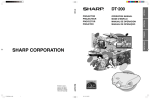
Be sure to read the following safeguards when setting up
your projector.
Caution concerning the lamp unit
Do not block the exhaust and intake vents.
■ Potential hazard of glass particles if lamp
ruptures. In case of lamp rupture, contact your nearest Sharp Authorised Projector Dealer or Service Centre for a replacement.
See “Replacing the Lamp” on page 54.
■ Allow at least 20 cm of space between the exhaust vent
and the nearest wall or obstruction.
■ Be sure that the intake vent and the exhaust vent are not
obstructed.
■ If the cooling fan becomes obstructed, a protection circuit
will automatically put the projector into the standby mode.
This does not indicate a malfunction. Remove the projector power cord from the wall outlet and wait at least 10
minutes. Place the projector where the intake and exhaust
vents are not blocked, plug the power cord back in and
turn on the projector. This will return the projector to the
normal operating condition.
BQC-PGB10S//1
Caution concerning the setup of the projector
■ For minimal servicing and to maintain high image quality,
SHARP recommends that this projector be installed in an
area free from humidity, dust and cigarette smoke. When
the projector is subjected to these environments, the lens
and part of filter must be cleaned more often than usual.
As long as the projector is properly maintained in this manner, use in these environments will not reduce the overall
operation life. Please note that all internal cleaning must
be performed by a Sharp Authorised Projector Dealer or
Service Centre.
Do not set up the projector in places exposed to
direct sunlight or bright light.
■ Position the screen so that it is not in direct sunlight or
room light. Light falling directly on the screen washes out
the colours, making viewing difficult. Close the curtains and
dim the lights when setting up the screen in a sunny or
bright room.
The projector may be safely tilted to a maximum
angle of 12 degrees.
■ Placement should be within ±12 degrees of horizontal.
Caution regarding transportation of the projector
■ When transporting the projector, be sure not to subject it
to hard impact and/or vibration, as this can result in damage. Take extra care with the lens. Before moving the projector, be sure to unplug the power cord from the wall outlet, and disconnect any other cables connected to it.
■ Do not carry the projector by holding the lens.
■ When transporting the projector, be sure to attach the lens
shipping block and the lens cap to the projector.
Other connected equipment
■ When connecting a computer or other audio-visual equipment to the projector, make the connections AFTER unplugging the power cord of the projector from the wall outlet and turning off the equipment to be connected.
■ Please read the operation manuals of the projector and
the equipment to be connected for instructions on how to
make the connections.
Using the projector in other countries
■ The power supply voltage and the shape of the plug may
vary depending on the region or country you are using the
projector in. When using the projector overseas, be sure
to use an appropriate power cord for the country you are
in.
12°
Do not subject the projector to hard impact and/or vibration.
■ Take care with the lens so as not to hit or damage the
surface of the lens.
Do not mount the projector on a ceiling by turning it over.
■ Use the lens shift feature when projecting the image from
a high position.
Rest your eyes occasionally.
Temperature monitor function
■ If the projector starts to overheat due
to setup problems or blockage of the
air vents, “
” and “
” will
illuminate in the lower left corner of
the picture. If the temperature continues to rise, the lamp will turn off, the temperature warning indicator on the projector will blink, and after a 90-second cooling-off period the projector will enter the standby
mode. Refer to “Maintenance Indicators” on page 52 for
details.
Info
•
■ Continuously watching the screen for long hours will cause
eye strain. Be sure to occasionally rest your eyes.
Avoid locations with extremes of temperature.
■ The operating temperature of the projector is from +5°C to
+35°C.
■ The storage temperature of the projector is from
–20°C to +60°C.
•
The cooling fan regulates the internal temperature, and its
performance is automatically controlled. The sound of the
fan may change during projector operation due to changes
in the fan speed. This does not indicate malfunction.
Do not unplug the power cord during projection or cooling
fan operation. This can cause damage due to rise in internal temperature, as the cooling fan also stops.
-7
XV_Z10E_E_p01_07.p65
7
03.11.7, 4:13 PM
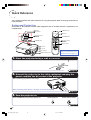
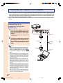
Quick Reference
This section introduces the quick reference for using the projector. Refer to the page for details on
each procedure.
Setup and Projection
Connection of the projector and the video equipment with an S-video terminal is explained as an
example below.
3 ON button
6 STANDBY button
4 INPUT button
3 ON button
5 Adjustment buttons
('"\ |)
5 KEYSTONE button
5 Adjustment buttons
('"\ |)
6 STANDBY button
4 INPUT 2 button
5 Zoom knob
5 Focus ring
5 Lens shift lever
Insert the batteries inside the
battery compartment of the
remote control. (See page 15.)
5 HEIGHT ADJUST button
1. Place the projector facing a wall or a screen
Page 16
2. Connect the projector to the video equipment and plug the
power cord into the AC socket of the projector
After connecting, play back the video image.
When connecting other devices, see pages 12, 22, 23, 24 and 25.
Pages 20, 21
3. Turn the projector on
Press the ON button to turn the projector on.
On the projector
On the remote control
Page 26
-8
XV_Z10E_E_p08_15.p65
8
03.11.7, 4:14 PM
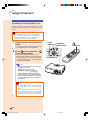
4. Select the INPUT mode
Select “INPUT 2” using the INPUT button on the projector or the INPUT 2 button on the remote control.
• When pressing
"On-screen Display
On the remote control
on the projector, input mode switches in order of
• When using the remote control, press
/
Introduction
On the projector
/
INPUT 1
INPUT 2
INPUT 3 .
to switch the input mode.
Page 27
5. Adjust the projected image
1 Bring the projected image into focus and adjust the projected image size
Focus
• Bring the projected
image into focus
using the focus ring.
Zoom
• Adjust the
projected
image size
using the
zoom knob.
Zoom in
Zoom out
Page 30
Page 30
2 Adjust the projected image position and the projector angle
Projection position
• Adjust the
projected
image position
using the lens
shift lever.
Angle
• Adjust the
projector
angle using
the HEIGHT
ADJUST
button.
Page 32
Page 31
3 Correct trapezoidal distortion
Correcting trapezoidal distortion using the Keystone Correction
Compresses upper side.
On the remote
control
Compresses lower side.
Page 29
6. Turn the power off
Press the STANDBY button, then press that button again while the confirmation message is displayed, to put
the projector into the standby mode.
"On-screen Display
On the projector
On the remote control
• Unplug the power cord from the wall outlet after the cooling fan stops.
Page 28
-9
XV_Z10E_E_p08_15.p65
9
03.11.7, 4:14 PM
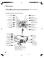
Part Names
Numbers in
refer to the main pages in this operation manual where the topic is explained.
The appearance of the product is subject to change without notice.
Projector (Front and Top View)
ON button
26
27
Power indicator
52
34
INPUT button
For switching input mode
1, 2 or 3.
For turning the power on.
RESIZE button
For switching the picture display
(STRETCH, SIDE BAR, etc.).
STANDBY button
28
29
For putting the projector into
the standby mode.
Lamp indicator
52
Temperature warning
indicator
52
UNDO button
29
Adjustment buttons
('"\ |)
• For selecting menu items.
• For adjusting the Keystone
Correction when in the
Keystone Correction mode.
For undoing an operation
or returning to the
previous display.
27
Volume buttons
37
ENTER button
For adjusting the speaker
sound level.
For setting items selected
or adjusted on the menu.
36
MENU button
For displaying adjustment
and setting screens.
Remote control
sensor
15
Power indicator
11
Lamp indicator
11
Temperature
warning indicator
11
Zoom knob
30
30
60
For adjusting the
projected image size.
Intake vent
Speaker
Front adjustment
foot
(on the bottom of
the projector)
31
HEIGHT ADJUST
button
31
32
Lens shift lever
For adjusting the
projection position
by moving the lens
up and down and
left and right (360°).
Attaching and removing the lens cap
• Press on the two buttons of the lens cap
and attach it to the lens, then release the
buttons to lock it in place.
• Press on the two buttons of the lens cap
and remove it from the lens.
-10
XV_Z10E_E_p08_15.p65
Focus ring
For bringing the
projected image
into the focus.
10
03.11.7, 4:14 PM
Introduction
About the Indicators on the Projector
Power indicator
Lamp indicator
Temperature
warning
indicator
Temperature
warning indicator
Lamp indicator
Maintenance indicators
Power indicator
Power indicator
Status of the lamp
Green on/Red on ... Normal
Red blinks ... Abnormal
Page
52
Lamp indicator
Green on ... Normal
Green blinks ... The lamp is warming up.
Red on ... Change the lamp.
52
Temperature
warning indicator
Off ... Normal
Red on ... The internal temperature is
abnormally high.
52
Attaching and Removing the Lens Shipping Block
When attaching the lens shipping block, be sure to return the lens shift
lever to the centre position. If the lens is shifted upwards or downwards,
the lens shipping block cannot be attached.
-11
XV_Z10E_E_p08_15.p65
11
03.11.7, 4:14 PM
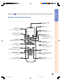
Part Names
Projector (Rear View)
INPUT 1 terminal
RS-232C terminal
Connecting the
computer to control the
projector.
(See page 25.)
Kensington Security
Standard connector
Connecting video equipment
with component output
terminal (DVD player, DTV
decoder, etc.). (See page 22.)
Connecting the computer.
(See page 24.)
INPUT 3 terminal
Connecting video equipment without
S-video output terminal. (See page 21.)
Remote control sensor (See page 15.)
AUDIO INPUT terminal
INPUT 2 terminal
Connecting video equipment with
S-video output terminal (VCR,
DVD player, etc.).
(See page 21.)
Connecting an audio cable
(Shared audio input terminal
for INPUT 1, 2 and 3). (See
pages 21 to 24.)
Using the Kensington Lock
• This projector has a Kensington Security Standard connector for use with a Kensington MicroSaver Security
System. Refer to the information that came with the system for instructions on how to use it to secure the
projector.
-12
XV_Z10E_E_p08_15.p65
12
03.11.7, 4:14 PM
refer to the main pages in this operation manual where the topic is explained.
Remote Control (Front View)
15
Remote control signal
transmitters
26
ON button
For turning the power on.
STANDBY button
28
For putting the projector into the
standby mode.
36
MENU button
For displaying adjustment and
setting screens.
KEYSTONE button
29
For entering the Keystone
Correction mode.
UNDO button
For undoing an operation or
returning to the previous display.
INPUT buttons
Adjustment buttons
(' " \ |)
• For selecting menu items.
• For adjusting the Keystone
Correction when in the Keystone
Correction mode.
29
37
ENTER button
For setting items selected or
adjusted on the menu.
27
For switching to the respective
input modes.
AUTO SYNC button
29
34
RESIZE button
For switching the picture display
(STRETCH, SIDE BAR, etc.).
46
For automatically adjusting images
when connected to a computer.
33
FREEZE button
For freezing images.
RGB/COMP. button
44
For switching the signal type (RGB
or Component).
Volume buttons
For adjusting the speaker sound
level.
44
PICTURE SETTING button
For selecting the memory
location.
27
28
MUTE button
For temporarily turning off the
sound.
-13
XV_Z10E_E_p08_15.p65
13
03.11.7, 4:14 PM
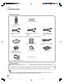
Introduction
Numbers in
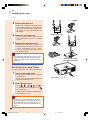
Accessories
Supplied accessories
Two AA size batteries
Remote control
Power cord*
(1)
(2)
For Europe, except U.K.
(1.8 m)
(3)
For Australia, New
Zealand and Oceania
(1.8 m)
For U.K., Hong Kong and
Singapore
(1.8 m)
* Use the power cord that corresponds to the wall outlet in your country.
Video cable
21 pin RCA
conversion adapter
(Supplied for Europe only)
Three RCA adapter plugs
3 RCA to 15-pin D-sub cable
(3.0 m)
Lens cap (attached)
Extra air filter
Operation manual
Lens shipping block (attached)
Optional accessory
■ Computer RGB cable (10.0 m)
AN-C10BM (15-pin mini D-sub male connector)
• Some cables cannot be used because of the shape of the connector. Check the specification
on the computer. You may need an adapter (commercially available) for connection.
Note
• Some of the accessories may not be available depending on the region. Please check with
your nearest Sharp Authorised Projector Dealer or Service Centre.
-14
XV_Z10E_E_p08_15.p65
14
03.11.7, 4:14 PM
Using the Remote Control
Introduction
Usable Range
The remote control can be used to control the
projector within the ranges shown in the illustration.
30°
Remote control sensor
30°
Note
• The signal from the remote control can be reflected off a screen for easy operation. However, the effective distance of the signal may
differ depending on the screen material.
When using the remote control:
• Be sure not to drop, expose to moisture or high
temperature.
• The remote control may malfunction under a
fluorescent lamp. In this case, move the projector away from the fluorescent lamp.
30°
30°
Remote
control
signal
transmitters
7m
30°
Remote control
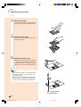
Inserting the Batteries
The batteries (two “AA” size) are supplied in
the package.
1
Press the ▲ mark on the cover
and slide it in the direction of the
arrow.
2
Insert the batteries.
3
Attach the cover and slide it until
it clicks into place.
• Insert the batteries making sure the polarities correctly match the
and
marks inside the battery compartment.
Incorrect use of the batteries may cause them to leak or explode. Please follow the precautions below.
Caution
• Insert the batteries making sure the polarities correctly match the
and
marks inside the battery compartment.
• Batteries of different types have different properties, therefore do not mix batteries of different types.
• Do not mix new and old batteries.
This may shorten the life of new batteries or may cause old batteries to leak.
• Remove the batteries from the remote control once they have run out, as leaving them in can cause them to leak.
Battery fluid from leaked batteries is harmful to skin, therefore be sure to first wipe them and then remove them
using a cloth.
• The batteries included with this projector may run down in a short period, depending on how they are kept. Be
sure to replace them as soon as possible with new batteries.
• Remove the batteries from the remote control if you will not be using the remote control for a long time.
-15
XV_Z10E_E_p08_15.p65
15
03.11.7, 4:14 PM
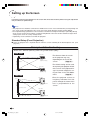
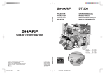
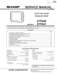
Setting up the Screen
Position the projector perpendicular to the screen with all feet flat and level (without using the adjustment
feet) to achieve an optimal image.
Note
• The projector lens should be centred in the middle of the screen. If the horizontal line passing through the
lens centre is not perpendicular to the screen, the image will be distorted, making viewing difficult.
• For an optimal image, position the screen so that it is not in direct sunlight or room light. Light falling directly
on the screen washes out the colours, making viewing difficult. Close the curtains and dim the lights when
setting up the screen in a sunny or bright room.
• A polarising screen cannot be used with this projector.
Standard Setup (Front Projection)
■ Place the projector at the required distance from the screen according to the desired picture size. (See
page 17.)
Example of standard setup
Screen size : 100 inch (254 cm) (when using a wide screen (16:9))
Side View
Lens centre
H1 : 1.2 m
Lower lens shift
position
(High mount setup)
Screen
• The distance from the screen
to the projector may vary
depending on the size of the
screen.
Page 17
• The default setting can be used,
Lens centre
H2
–14.8 cm
Upper lens shift
position
(Desktop setup)
Top View
Lens centre
W : 2.2 m
Screen
Leftmost lens shift
position
when placing the projector in front
of the screen. If the projected image is reversed, readjust the setting to “Front” in the “PRJ Mode”
menu.
Page 51
• Place the projector so that an
imaginary horizontal line that
passes through the centre of the
lens is perpendicular to the
screen.
Centre of screen
Lens centre
Rightmost lens shift
position
-16
XV_Z10E_E_p16_18.p65
16
03.11.7, 4:14 PM
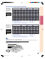
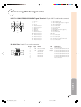
Screen Size and Projection Distance
When using a wide
screen (16:9)
In case of displaying
the 16:9 picture on the
whole of the 16:9
screen.
Picture (Screen) size
Diag. [χ ]
16
9
: Picture area
When using a normal
screen (4:3)
In case of setting the
16:9 picture to the full
horizontal width of the
4:3 screen.
Left
Right
300
6.6 m
3.7 m
Minimum [L1] Maximum [L2] Lower [H1] Upper [H2]
9.2 m
11.5 m
418.5 cm
–44.3 cm
178.5 cm
178.5 cm
250
5.5 m
3.1 m
7.7 m
9.6 m
348.8 cm
–36.9 cm
148.8 cm
148.8 cm
225
5.0 m
2.8 m
6.9 m
8.6 m
313.9 cm
–33.2 cm
133.9 cm
133.9 cm
200
4.4 m
2.5 m
6.1 m
7.7 m
279.0 cm
–29.5 cm
119.0 cm
119.0 cm
150
3.3 m
1.9 m
4.6 m
5.7 m
209.3 cm
–22.1 cm
89.3 cm
89.3 cm
133
2.9 m
1.7 m
4.1 m
5.1 m
185.5 cm
–19.6 cm
79.1 cm
79.1 cm
106
2.4 m
1.3 m
3.2 m
4.0 m
147.9 cm
–15.6 cm
63.1 cm
63.1 cm
100
2.2 m
1.3 m
3.0 m
3.8 m
139.5 cm
–14.8 cm
59.5 cm
59.5 cm
92
2.0 m
1.2 m
2.8 m
3.5 m
128.3 cm
–13.6 cm
54.7 cm
54.7 cm
84
1.9 m
1.1 m
2.6 m
3.2 m
117.2 cm
–12.4 cm
50.0 cm
50.0 cm
72
1.6 m
0.9 m
2.2 m
2.7 m
100.4 cm
–10.6 cm
42.8 cm
42.8 cm
60
1.3 m
0.7 m
1.8 m
2.3 m
83.7 cm
–8.9 cm
35.7 cm
35.7 cm
40
0.9 m
0.5 m
1.2 m
1.5 m
55.8 cm
–5.9 cm
23.8 cm
23.8 cm
Picture size (diag.) (inch)
Projection distance (m)
Minimum projection distance (m)
Maximum projection distance (m)
Distance from the lens centre to the bottom of the image (cm)
Lower distance from the lens centre to the bottom of the image (cm)
Upper distance from the lens centre to the bottom of the image (cm)
Distance from the lens centre to the centre of the image (cm)
Picture (Screen) size
Diag. [χ ]
4
3
: Screen area
: Picture area
Height
Distance from the lens centre to Distance from the lens centre to
the bottom of the image [H]
the centre of the image [W]
χ:
L:
L1:
L2:
H:
H1:
H2:
W:
Width
Projection distance [L]
Height
Connections and Setup
χ:
L:
L1:
L2:
H:
H1:
H2:
W:
Width
Projection distance [L]
The formula for picture size and
projection distance
L1 (m) = 0.0308χ – 0.035
L2 (m) = 0.0385χ – 0.035
H1 (cm) = 1.395χ
H2 (cm) = 0.1475χ
W (cm) = 0.595χ
Distance from the lens centre to Distance from the lens centre to
the bottom of the image [H]
the centre of the image [W]
Left
Right
300
6.1 m
4.6 m
Minimum [L1] Maximum [L2] Lower [H1] Upper [H2]
8.5 m
10.6 m
384.3 cm
–40.6 cm
163.5 cm
163.5 cm
250
5.1 m
3.8 m
7.0 m
8.8 m
320.3 cm
–33.8 cm
136.3 cm
136.3 cm
200
4.1 m
3.0 m
5.6 m
7.0 m
256.2 cm
–27.0 cm
109.0 cm
109.0 cm
150
3.0 m
2.3 m
4.2 m
5.3 m
192.2 cm
–20.3 cm
81.8 cm
81.8 cm
100
2.0 m
1.5 m
2.8 m
3.5 m
128.1 cm
–13.5 cm
54.5 cm
54.5 cm
84
1.7 m
1.3 m
2.3 m
2.9 m
107.6 cm
–11.4 cm
45.8 cm
45.8 cm
72
1.5 m
1.1 m
2.0 m
2.5 m
92.2 cm
–9.7 cm
39.2 cm
39.2 cm
60
1.2 m
0.9 m
1.7 m
2.1 m
76.9 cm
–8.1 cm
32.7 cm
32.7 cm
40
0.8 m
0.6 m
1.1 m
1.4 m
51.2 cm
–5.4 cm
21.8 cm
21.8 cm
Picture size (diag.) (inch)
Projection distance (m)
Minimum projection distance (m)
Maximum projection distance (m)
Distance from the lens centre to the bottom of the image (cm)
Lower distance from the lens centre to the bottom of the image (cm)
Upper distance from the lens centre to the bottom of the image (cm)
Distance from the lens centre to the centre of the image (cm)
The formula for picture size and
projection distance
L1 (m) = 0.0283χ – 0.032
L2 (m) = 0.0353χ – 0.032
H1 (cm) = 1.281χ
H2 (cm) = 0.1352χ
W (cm) = 0.545 χ
Note
• There may be an error of ± 3% in the above values.
• Values with a minus (–) sign indicate the distance from the lens centre below the bottom of the image.
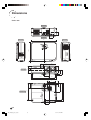
Indication of the Projection Image Size and Projection Distance
Example : When using a wide screen (16:9)
Picture Size
300"
6.6 m
m
Cen
tre
Proje
Dist ction
ance
.5
11
–
m
9.
2
–
–
m
3.
0
m
m
7.
7
2
–
m
6
2.
m
m
3.
3
2.
–
m
8
1.
m
m
1.3
m
1.3
m
0.7 ×
m
m×
1.1
2.5
× 3.7
6.
1
2.2
m×
m
60"
1.9
m×
m
100"
84"
4.4
3.
8
200"
-17
XV_Z10E_E_p16_18.p65
17
03.11.7, 4:14 PM
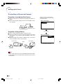
Setting up the Screen
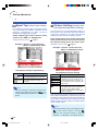
Projecting a Reversed Image
Projection from behind the Screen
■ Place a translucent screen between the projector and the audience.
■ Reverse the image by setting “Rear” in the “PRJ Mode” menu.
(See page 51.)
Audience
When the image is projected from
behind the translucent screen using
the default setting.
▼On-screen Display
Translucent screen
Set to “Rear”.
Projection Using a Mirror
■ Place a mirror (normal flat type) in front of the lens.
■ When the translucent screen is placed on between the mirror
and audience, set to “Front” in the “PRJ Mode” menu. (See
page 51.)
■ When the mirror is placed on the audience side, set to “Rear”
in the “PRJ Mode” menu. (See page 51.)
Set to “Front”.
▼On-screen Display
Set to “Rear”.
Mirror
The image is reversed.
Translucent screen
Audience
Audience
Mirror
Info
• When using a mirror, be sure to carefully position both the projector and the mirror so the light does not shine into the eyes of
the audience.
-18
XV_Z10E_E_p16_18.p65
18
03.11.7, 4:14 PM
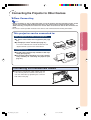
Connecting the Projector to Other Devices
Before Connecting
Note
• Before connecting, be sure to unplug the power cord of the projector from the wall outlet and turn off the
devices to be connected. After making all connections, turn on the projector and then the other devices.
When connecting a computer, be sure that it is the last device to be turned on after all the connections are
made.
• Be sure to read the operation manuals of the devices to be connected before making connections.
Connections and Setup
This projector can be connected to:
Video equipmeent or audio-visual equipment:
■ A VCR or other audio-visual equipment (See page
21.)
■ A DVD player or DTV* decoder (See page 22.)
*DTV is the umbrella term used to describe the new
digital television system in the United States.
A computer using:
■ An RGB cable (commercially available or sold separately) (See page 24.)
■ An RS-232C cable (null modem, cross type, commercially available) for controlling the projector (See
page 25.)
Connecting the thumbscrew cables
■ Connect the thumbscrew cable making sure that
it fits correctly into the terminal. Then, firmly secure the connectors by tightening the screws on
both sides of the plug.
-19
XV_Z10E_E_p19_25.p65
19
03.11.7, 4:15 PM
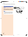
Connecting the Projector to Other Devices
Connecting the Power
Cord
Supplied
Power cord
accessory
Plug the supplied power cord into the
AC socket on the rear of the projector.
Note
• The projector is put into standby mode by
plugging the power cord into the wall outlet
after first turning the projector off and then
unplugging the power cord from the wall outlet.
-20
XV_Z10E_E_p19_25.p65
20
03.11.7, 4:15 PM
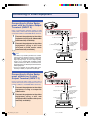
Connecting to Video Equipment
Connecting to Video Equipment with an S-video Output
Terminal (INPUT 2)
1
Connect the projector to the video
equipment using an S-video cable
(commercially available).
2
Connect the projector to the video
equipment using a ø3.5 mm
minijack to RCA audio cable
(commercially available).
To INPUT 2 terminal
S-video cable
(commercially available)
To S-video output
terminal
To AUDIO INPUT
terminal
ø3.5 mm minijack to
RCA audio cable
(commercially
available)
To audio output
terminal
Note
• The INPUT 2 (S-VIDEO) terminal uses a video
signal system in which the picture is separated
into colour and luminance signals to realise a
higher-quality image. To view a higher-quality
image, use a commercially available S-video
cable to connect the INPUT 2 terminal on the
projector and the S-video output terminal on the
video equipment.
• A ø3.5 mm minijack to RCA audio cable (commercially available) is required for audio input.
VCR or other audio-visual equipment
Connecting to Video Equipment without an S-video
Output Terminal (INPUT 3)
Using a composite video cable or audio cable, a
VCR or other audio-visual equipment can be connected to INPUT 3 and AUDIO INPUT terminals.
1
2
Connect the projector to the video
equipment using a composite
video cable.
Connect the projector to the video
equipment using a ø3.5 mm
minijack to RCA audio cable (commercially available).
To INPUT 3 terminal
Composite video cable
To video output
terminal
To AUDIO INPUT
terminal
ø3.5 mm minijack to
RCA audio cable
(commercially
available)
To audio output
terminal
VCR or other audio-visual equipment
-21
XV_Z10E_E_p19_25.p65
21
03.11.7, 4:15 PM
Connections and Setup
Using a commercially available S-video or audio
cable, a VCR or other audio-visual equipment can be
connected to INPUT 2 and AUDIO INPUT terminals.
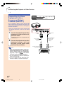
Connecting the Projector to Other Devices
Connecting to Video
Equipment with a
Component Output
Terminal (INPUT 1)
Supplied
accessory
3 RCA to 15-pin D-sub cable
(3.0 m)
Use a supplied 3 RCA to 15-pin D-sub cable
when connecting to the INPUT 1 terminal, component video equipment such as DVD players
and DTV* decoders.
* DTV is the umbrella term used to describe the
new digital television system in the United
States.
1
Connect the projector to the video
equipment using the 3 RCA to 15pin D-sub cable.
• Secure the connectors by tightening the
thumbscrews.
2
Connect the projector to the video
equipment using a ø3.5 mm
minijack to RCA audio cable
(commercially available).
To AUDIO INPUT
terminal
To INPUT 1
terminal
ø3.5 mm minijack to
RCA audio cable
(commercially
available)
3 RCA to 15-pin
D-sub cable
(supplied)
To analog component
output terminal
Note
• When connecting the projector to the component video equipment, set “Signal Type”
on the “Picture” menu to “Component”
on the remote
(page 44), or press
control to select the component input.
• Set “Special Mode” to “480P” for inputting the
525P signal (page 45).
• A ø3.5 mm minijack to RCA audio cable (commercially available) is required for audio input.
To audio output
terminal
DVD player or DTV* decoder
-22
XV_Z10E_E_p19_25.p65
22
03.11.7, 4:15 PM
Extending the connecting cables
■ Use three RCA adapter plugs (supplied) for the following connection.
(Example)
3 RCA to 15-pin
D-sub cable
(supplied)
Three RCA adapter
plugs (supplied)
RCA cables
(commercially available)
Connections and Setup
Ferrite cores
Info
• Do not remove ferrite cores attached to the 3 RCA to 15-pin D-sub cable.
-23
XV_Z10E_E_p19_25.p65
23
03.11.7, 4:15 PM
Connecting the Projector to a Computer
• Before connecting, be sure to unplug the power cord of the projector from the wall outlet and
turn off the devices to be connected. After making all connections, turn on the projector and
then the other devices. When connecting a computer, be sure that it is the last device to be
turned on after all the connections are made.
• Be sure to read the operation manuals of the devices to be connected before making connections.
Connecting to a
Computer Using the
RGB Cable
1
Connect the projector to the computer using the RGB cable (commercially available or sold separately).
To INPUT 1 terminal
• Secure the connectors by tightening the
thumbscrews.
2
To input an audio signal, connect
the projector to the computer using a ø3.5 mm stereo or mono
audio cable (commercially available).
RGB cable
To AUDIO INPUT
terminal
ø3.5 mm stereo
or mono audio
cable
(commercially
available)
Note
• When connecting the projector to the computer, set “Signal Type” on the “Picture”
menu to “RGB” (page 44), or press
To RGB output
terminal
To audio output
terminal
on the remote control to select the RGB
input.
• See page 59 “Computer Compatibility Chart”
for a list of computer signals compatible with
the projector. Use with computer signals other
than those listed may cause some of the functions to not work.
• A Macintosh adapter may be required for using the computer cable to connect to some
Macintosh computers. Contact your nearest
Sharp Authorised Projector Dealer or Service
Centre.
• Depending on the computer you are using,
an image may not be projected unless the signal output setting of the computer is switched
to the external output. Refer to the computer
operation manual for switching the computer
signal output settings.
• When using the ø3.5 mm mono audio cable,
the volume level will be half of when using
the ø3.5 mm stereo audio cable.
Computer
-24
XV_Z10E_E_p19_25.p65
24
03.11.7, 4:15 PM
Controlling the Projector Using a Computer
Connecting to a
Computer Using an RS232C Cable
1
Connect one end of the RS-232C
cable (null modem, cross type) to
the RS-232C terminal on the projector.
2
Connect the other end of the RS232C cable to the RS-232C terminal on the computer.
Connections and Setup
When the RS-232C terminal on the projector is
connected to a computer with an RS-232C
cable (null modem, cross type, commercially
available), the computer can be used to control the projector. See page 58 for details.
To RS-232C terminal
RS-232C cable
(commercially available)
To RS-232C terminal
Note
• The RS-232C function may not operate if your
computer terminal is not correctly set up. Refer to the operation manual of the computer
for details.
• See page 57 for connection of an RS-232C
cable.
• A Macintosh adapter may be required for using the computer cable to connect to some
Macintosh computers. Contact your nearest
Sharp Authorised Projector Dealer or Service
Centre.
Computer
Info
• Do not connect the RS-232C cable to a port
other than the RS-232C terminal on the computer. This may damage your computer or projector.
• Do not connect or disconnect an RS-232C
cable to or from the computer while it is on.
This may damage your computer.
-25
XV_Z10E_E_p19_25.p65
25
03.11.7, 4:15 PM
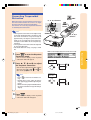
Image Projection
Turning the Projector on
Connect the required external equipment to the
projector before carrying out the following procedures.
Info
• The language preset at the factory is English.
If you want to change the on-screen display
to another language, reset the language according to the procedure on page 51.
1
Plug the power cord into the wall
outlet.
• The power indicator illuminates red, and
the projector enters standby mode.
2
Power
indicator
ON button
INPUT button
Press
on the projector or
on the remote control.
• The power indicator illuminates green.
• When the lamp turns on, the lamp indicator illuminates green. After the lamp indicator illuminates green, the projector is
ready to start operation.
Lamp indicator
Note
• The lamp indicator illuminates, indicating
the status of the lamp.
Green: The lamp is ready.
Blinking in green: The lamp is
warming up.
Red: The lamp should be replaced.
• If the projector is put into the standby
mode and immediately turned on again,
the lamp indicator may take some time
to illuminate.
Info
• See page 30 for details about adjusting
the focus and the size of the projected
image.
• See “Using the Adjustment Feet” on page
31 for adjusting the projector angle and
“Variable Lens Shift Feature” on page 32
for adjusting the projected image position.
-26
XV_Z10E_E_p26_35.p65
26
03.11.7, 4:15 PM
ON button
Switching the INPUT
Mode
Select the appropriate input mode for the connected equipment.
Press
,
or
on the remote
control to select the INPUT mode.
"On-screen Display of INPUT Mode (Example)
INPUT 1 mode
➝
• When pressing
on the projector, input mode
switches in order of
INPUT 1 INPUT 2 INPUT 3
.
INPUT buttons
Using
Component
Note
Using RGB
INPUT 2 mode
Using S-Video
INPUT 2
(S-Video)
INPUT 3
(Video)
Used for projecting images from equipment that sends component signals or
RGB signals connected to the INPUT 1
terminal.
Used for projecting images from
equipment connected to the INPUT 2
terminal.
Used for projecting images from
equipment connected to the INPUT 3
terminal.
INPUT 3 mode
Using Video
Basic Operation
INPUT 1
(Component/RGB)
➝
About the INPUT mode
➝
• When no signal is received, “NO SIGNAL” will
be displayed. When a signal that the projector is not preset to receive is received, “NOT
REG.” will be displayed.
• The INPUT mode is not displayed when “OSD
Display” of the “Options” menu is set to
” (OFF). (See page 47.)
“
Volume buttons
Adjusting the Volume
Press
or
on the remote control to adjust the volume.
Note
Volume
buttons
• Pressing
will lower the volume.
Pressing
will raise the volume.
• On the projector, the volume can be adjusted
by pressing
or
.
"On-screen Display
-27
XV_Z10E_E_p26_35.p65
27
03.11.7, 4:15 PM
Image Projection
Turning off the Sound
Temporarily
Press
on the remote control to temporarily turn off the sound.
Note
• Pressing
on.
again will turn the sound back
Turning the Power off
"On-screen Display
(Putting
STANDBY
button
the Projector into the Standby Mode)
1
MUTE button
Press
on the projector or
on the remote control, then
press that button again while the
confirmation message is displayed, to put the projector into
the standby mode.
"On-screen Display
Note
• If you accidentally pressed
or
and do not want to put the projector into the standby mode, wait until the
confirmation message disappears.
2
Unplug the power cord from the wall
outlet after the cooling fan stops.
Info
• Do not unplug the power cord during projection or cooling fan operation. The cooling fan in this projector continues to run
for about 90 seconds after the projector enters the standby mode. This can cause
damage due to rise in internal temperature,
as the cooling fan also stops.
-28
XV_Z10E_E_p26_35.p65
28
03.11.7, 4:15 PM
Correcting Trapezoidal
Distortion
When the image is projected either from the top or
from the bottom towards the screen at an angle,
the image becomes distorted trapezoidally.
The function for correcting trapezoidal distortion
is called Keystone Correction.
', ", \, |
buttons
KEYSTONE
button
UNDO
button
Note
• The Keystone Correction can be adjusted up
to an angle of approximately ±30 degrees and
the screen can also be set up to an angle of
approximately ±30 degrees (when the resize
mode is set to “STRETCH” for the video signal input or “SIDE BAR” for the computer signal input).
• The Keystone Correction cannot be adjusted
in the lateral direction.
• For details about the setup, see pages 7 and
16.
UNDO button
', ", \, |
buttons
"On-screen display (Keystone Correction mode)
Press
to enter the Keystone
Correction mode.
• The on-screen display of the Keystone
Correction mode will appear.
2
Basic Operation
1
Compresses
upper side.
Press ', ", \ and | to adjust
the Keystone Correction.
• You can also adjust the Keystone Correction using the
,
tons on the projector.
,
and
but-
Compresses
lower side.
Note
• Press
to return to the default setting.
• Straight lines or the edges of images
may appear jagged while adjusting the
image.
• When correcting trapezoidal distortion,
the aspect ratio of the image will change
slightly .
3
Press
.
• The on-screen display of the Keystone
Correction mode will disappear.
-29
XV_Z10E_E_p26_35.p65
29
03.11.7, 4:15 PM
Image Projection
Adjusting the Lens
The image is focused and adjusted to the desired size using the focus ring or zoom knob
on the projector.
1
Adjust the focus by rotating the
focus ring.
2
Adjust zooming by moving the
zoom knob.
Zoom knob
Focus ring
m in
Zoo
m
Zoo
out
-30
XV_Z10E_E_p26_35.p65
30
03.11.7, 4:15 PM
Using the Adjustment
Feet
The height of the projector can be adjusted using the adjustment feet at the front and rear of
the projector when the screen is not perpendicular to the lens centre of the projector, or
when installation surface is slightly slanted.
When the screen is in a higher position than
the projector, the projection image can be made
higher by adjusting the projector.
1
Press the HEIGHT ADJUST button.
2
Lift the projector to adjust its
height while pressing the HEIGHT
ADJUST button.
HEIGHT ADJUST
button
• The front adjustment foot comes out.
3
Remove your hands from the
HEIGHT ADJUST button of the
projector after its height has been
finely adjusted.
4
Use the rear adjustment foot to
make the projector level.
HEIGHT ADJUST button
Front adjustment
foot
Basic Operation
• The projector is adjustable up to approximately 12 degrees (5 steps).
• When lowering the projector, it may be
difficult to move the front adjustment foot
because the installation surface is difficult
to slide. In this case, pull the projector back
slightly and adjust its height.
• The projector is adjustable ±1 degree from
the standard position.
Note
• When the height of the image is being adjusted
by the adjustment feet, the image becomes distorted trapezoidally. In this case, see “Correcting Trapezoidal Distortion” on page 29 to correct the trapezoidal distortion.
Info
Rear adjustment
foot
• Do not press the HEIGHT ADJUST button
when the front adjustment foot comes out
without firmly holding the projector.
• Do not hold the lens when lifting or lowering
the projector.
• When lowering the projector, be careful not to
get your fingers caught in the area between
the adjustment foot and the projector.
-31
XV_Z10E_E_p26_35.p65
31
03.11.7, 4:15 PM
Image Projection
Variable Lens Shift Feature
In addition to the zoom function and adjustment of projection angle using the adjustment foot, it is possible
to move the lens up and down and left and right (360°) to adjust the projection position simply by moving
the lens shift lever on the front of the projector. This is a useful function in cases such as when the screen
cannot be moved.
When moving upwards or downwards
When moving in the left and right direction
ge
Adjustable ran
ge
Adjustable ran
Adjustable range
Adjustable range
Lens shift lever
Lens shift lever
Adjustable range of the lens shift lever
The adjustable range using the lens shift lever has limitations.
The image can be adjusted as shown below.
Image centre locus
Zooming axis
Adjustable range of
the image centre
Image centre
Height of the
projected
image × (about) 60%
Width of the projected
image × (about) 30%
-32
XV_Z10E_E_p26_35.p65
32
03.11.7, 4:15 PM
Adjusting the Projected
Image Position
Adjust the projected image position
using the lens shift lever.
Info
• When using the projector (during projection),
be sure not to subject the projector to any
impact. If the projector is subjected to impact,
the projection image may deviate from the
adjusted position.
• When transporting or carrying the projector,
attach the lens shipping block and the lens
cap to the projector.
• When the angle is being adjusted using the
adjustment foot, deviation of the projected
image arising when carrying out lens shift in
the lateral direction cannot be corrected by
the Keystone Correction.
Basic Operation
Freeze Image
You can instantly freeze a moving image with
the remote control.
Freezing a Moving
Image
1
2
Press
.
• The projected image is frozen.
FREEZE button
Press
again to return to the
moving image from the currently
connected device.
-33
XV_Z10E_E_p26_35.p65
33
03.11.7, 4:15 PM
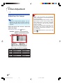
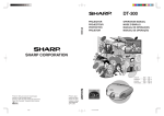
Selecting the Picture Display Mode
This function allows you to modify or customise the picture display mode to enhance
the input image. Depending on the input signal, you can choose “STRETCH”, “SIDE
BAR” or “CINEMA ZOOM” image.
Switching the Picture
Display Using Different
Input Signals
Press
• Pressing
UNDO
button
.
RESIZE button
changes the picture display mode
as shown on page 35.
• To return to the standard image (“STRETCH”),
press
while “RESIZE” is displayed on the
screen.
• You can also change the picture display mode
by pressing
on the projector.
RESIZE button
UNDO button
-34
XV_Z10E_E_p26_35.p65
34
03.11.7, 4:16 PM
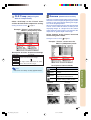
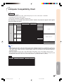
Input Signal
Output screen image
STRETCH
SIDE BAR
CINEMA ZOOM
(Default setting)
4:3 aspect ratio
480I
480P
NTSC
PAL
SECAM
Letter box
Squeezed
1080I
16:9 aspect ratio
720P
Basic Operation
VGA
SVGA
XGA
4:3 aspect ratio
: Cutout area on which images cannot be projected.
Note
• “STRETCH” is fixed when 720P or 1080I signals are entered.
-35
XV_Z10E_E_p26_35.p65
35
03.11.7, 4:16 PM
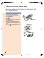
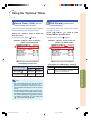
Using the Menu Screen
The menu screens allow you to adjust the image and various projector settings. (The menu items differ
depending on the input mode.)
The menu can be operated with the projector or with the remote control.
', ", \, | buttons
Menu Selections
ENTER button
(Adjustments)
1
Press
.
Note
MENU button
• The “Picture” menu screen for the selected input mode is displayed.
ENTER
button
UNDO
button
MENU button
', ", \, |
buttons
-36
XV_Z10E_E_p36_41.p65
36
03.11.7, 4:17 PM
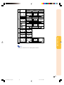
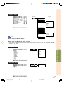
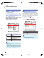
2
Select the icon.
Press \ or | to select the menu
screen (icon) you want to set.
• The menu icon for the selected menu
screen is highlighted.
Menu icon
Menu screen
Picture
Fine Sync
Options
Language
PRJ Mode
Note
• The “Fine Sync” menu is not available
for INPUT 2 or 3.
• For items on the menus, see the tree
charts on pages 40 and 41.
3
Press ' or " to select the item
you want to adjust.
• The selected item is highlighted.
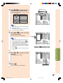
Select the
item.
Note
• If you want to adjust the item while viewafing the projected image, press
ter selecting the item. Only the selected
adjustment item will be displayed.
When pressing ' or ", the following
item (“Bright” after “Contrast”) will be
displayed.
• Press
screen.
Adjustments and Settings
4
to return to the previous
Press \ or | to adjust the item
selected.
• The adjustment is stored.
5
Press
.
• The menu screen will disappear.
Adjust the item or
make the setting.
-37
XV_Z10E_E_p36_41.p65
37
03.11.7, 4:17 PM
Using the Menu Screen
', ", \, | buttons
Menu Selections
ENTER button
(Settings)
1
Press
.
Note
MENU button
• The “Picture” menu screen for the selected input mode is displayed.
ENTER
button
UNDO
button
MENU button
', ", \, |
buttons
2
Press \ or | to select the menu
screen (icon) you want to set.
Select the icon.
• The menu icon for the selected menu
screen is highlighted.
Menu icon
Menu screen
Picture
Fine Sync
Options
Language
PRJ Mode
Note
• The “Fine Sync” menu is not available
for INPUT 2 or 3.
• For items on the menus, see the tree
charts on pages 40 and 41.
-38
XV_Z10E_E_p36_41.p65
38
03.11.7, 4:17 PM
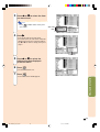
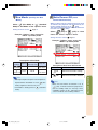
3
Press ' or " to select the item
you want to set.
Note
• Press
or \ to return to the previous screen.
4
Select the
item.
Press |.
• The cursor shifts to the sub menu.
• For some items, the sub menu cannot be
displayed. In such cases, select the icon using \ or | to make a setting, then go to
step 7.
Sub menu
5
Press ' or " to select the
setting of the item displayed
in the sub menu.
6
Press
7
Press
.
• The item selected is set.
.
Adjustments and Settings
• The menu screen will disappear.
-39
XV_Z10E_E_p36_41.p65
39
03.11.7, 4:18 PM
Menu Items
The following shows the items that can be set in the projector.
“Picture” menu
Main menu
Picture
Page 42
Sub menu
Contrast
−30
+30
Bright
−30
+30
Color
−30
+30
Tint
−30
+30
Sharp
−30
+30
Red
−30
+30
Blue
−30
+30
Reset
Page 42
CLR Temp
5500K
6500K
7500K
8500K
9300K
10500K
Page 43
Note
Gamma
Standard
Cinema1
Cinema2
Brighten
Page 43
When using the INPUT 1 mode:
• In the “Picture” menu of INPUT 1, “Color”, “Tint” and
“Sharp” are only displayed when “Signal Type” is set to
“Component”.
• “Signal Type” is displayed in the “Picture” menu only in
the INPUT 1 mode.
Signal Type
RGB
Component
Page 44
Picture Setting
Memory 1
Memory 5
Memory OFF
Page 44
When using the INPUT 2 or INPUT 3 mode:
• The “Signal Type” item does not appear in the “Picture”
menu.
• “Sharp” is adjustable between –3 and +3.
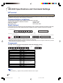
“Fine Sync” menu
Fine Sync
Page 45
Clock
−30
+30
Phase
−15
+15
H-Pos
−30
+30
V-Pos
−30
+30
Reset
Page 45
Special Modes
Page 45
Auto Sync [ON/OFF]
640 × 480
720 × 480
480P
Page 46
Signal Info
Page 46
Note
Resolution
Hor Freq
Vert Freq
480P
31 kHz
60 Hz
When using the INPUT 1 mode:
• The “Fine Sync” menu is only displayed when the projector input is INPUT 1.
• The values for “Resolution”, “Hor Freq” and “Vert Freq” in the tree chart are examples only.
• “Clock”, “Phase” and “Auto Sync” cannot be adjusted when “Signal Type” is set to “Component”.
-40
XV_Z10E_E_p36_41.p65
40
03.11.7, 4:18 PM
“Options” menu
Main menu
Options
Page 47
Sub menu
Lamp Timer (Life)
Page 47
OSD Display [ON/OFF]
Page 47
Video System
Page 48
Auto
PAL
NTSC3.58
SECAM
NTSC4.43
PAL-M
PAL-N
PAL-60
Background [Blue/None]
Page 48
Eco Mode [Eco/Standard]
Page 49
Auto Power Off [ON/OFF]
Page 49
Menu Position
Page 50
Note
Center
Upper Right
Lower Right
Upper Left
Lower Left
Menu Color
[Opaque/Translucent]
Page 50
When using the INPUT 1 mode:
• The “Video System” item does not appear in the “Options” menu.
When using the INPUT 2 or INPUT 3 mode:
• “Tint” cannot be adjusted in the “Picture” menu when “Video System” is set to “PAL”, “SECAM”, “PAL-M”,
“PAL-N” or “PAL-60”.
“Language” menu
Page 51
English
Deutsch
Español
Nederlands
Français
Italiano
Svenska
Português
Adjustments and Settings
Language
“PRJ Mode” menu
PRJ Mode
Page 51
Front
Rear
-41
XV_Z10E_E_p36_41.p65
41
03.11.7, 4:18 PM
Picture Adjustment
Adjusting the Image
Note
• Select the memory location (Memory 1 to 5, or
Memory OFF) first when you want to store the
adjustment settings on the “Picture” menu. (See
page 44.)
Select the item on the “Picture” menu and
adjust the image.
Adjusting the menu screen
Page 36
Example: “Picture” screen menu for
INPUT 1 (Component) mode
Info
• “Color”, “Tint” and “Sharp” are not displayed
when selecting INPUT 1 and setting the “Signal Type” to “RGB”.
• “Tint” cannot be adjusted and “Sharp” is adjustable between –3 and +3 in the “Picture” menu
when “Video System” is set to “PAL”, “SECAM”,
“PAL-M”, “PAL-N” or “PAL-60” for the INPUT 2
or INPUT 3 mode.
• “Sharp” can be adjusted when 480I, 480P, 540P,
580I, 580P, 720P, 1035I or 1080I signals are
detected while “Signal Type” for INPUT 1 is set
to “Component”.
• To reset all adjustment items, select “Reset” and
press
.
Description of Adjustment Items
Selectable items
Contrast
Bright
Color
Tint
Sharp
Red
Blue
Press \
Press |
for less contrast.
for less brightness.
for less colour intensity.
for making skin tones purplish.
for less sharpness.
for weaker red.
for weaker blue.
for more contrast.
for more brightness.
for more colour intensity.
for making skin tones greenish.
for more sharpness.
for stronger red.
for stronger blue.
-42
XV_Z10E_E_p42_47.p65
42
03.11.14, 10:30 AM
CLR Temp
(Adjusting the
Colour Temperature)
Select “CLR Temp” on the “Picture” menu
and the desired colour temperature setting.
Setting the menu screen
Page 38
Example: “Picture” screen menu for
INPUT 1 (Component) mode
Gamma
(Gamma Correction)
Gamma is an image quality enhancement function
that offers a richer image by brightening the darker
portions of the image without altering the brightness of the brighter portions.
When you are displaying images with frequent dark
scenes, such as a film or concert, or when you are
displaying images in a bright room, this feature
makes the dark scenes easier to see and gives the
impression of greater depth in the image.
Select “Gamma” on the “Picture” menu and
the desired gamma mode.
Setting the menu screen
Page 38
Example: “Picture” screen menu for
INPUT 1 (Component) mode
Description of Colour Temperature Settings
Selectable settings
5500K
6500K
7500K
8500K
9300K
10500K
Description
For lower colour temperature for warmer,
reddish incandescent-like images.
For higher colour temperature for cooler,
bluish, fluorescent-like images.
Description of Gamma Modes
Selectable settings
Note
—
Cinema1
Gives greater depth to darker portions
of images.
Cinema2
Brightness is toned down and the
image becomes more balanced.
Brighten
Brightens the darker portions of images
for easier viewing in a dimly lit room.
Standard
Cinema1
Cinema2
Brighten
Adjustments and Settings
• Values for “CLR Temp” are only approximations.
Description
Standard
-43
XV_Z10E_E_p42_47.p65
43
03.11.7, 4:18 PM
Picture Adjustment
Signal Type (Signal Type Setting)
In accordance with the input signal from the device connected to the INPUT 1 terminal on the
projector, “Component” or “RGB” can be selected for the signal type setting.
Select “Signal Type” on the “Picture” menu
and set it to “RGB” or “Component”.
Setting the menu screen
Page 38
Example: “Picture” screen menu for
INPUT 1 (Component) mode
Picture Setting
(Storing and
Selecting the Adjustment Settings)
Use this function to store the adjustment settings on
the “Picture” menu. No matter which input mode or
signal type is selected, you can select and apply the
settings you have stored in a memory location.
Select “Picture Setting” on the “Picture” menu and the
memory location where you want to store the settings.
Then adjust the setting items on the “Picture” menu.
Setting the menu screen
Page 38
Example: “Picture” screen menu for
INPUT 1 (Component) mode
Description of Signal Type Settings
Selectable settings
Description
Description of Picture Setting
Selectable settings
RGB
Set when RGB signals are received.
Component
Set when Component signals are
received.
Memory 1
Memory 2
Memory 3
Memory 4
Memory 5
Memory OFF
Note
• You can change the signal type setting on the
on the
“Signal Type” display by pressing
remote control when the INPUT 1 mode is selected.
Description
Settings of all items (except for
“Signal Type”) on the “Picture” menu
can be stored in memory location. The
stored settings can be selected in any
input mode.
Settings on the “Picture” menu for
each input mode can be stored. The
settings stored in “Memory OFF”
cannot be applied when another input
mode is selected.
If you want to apply the stored settings on the “Picture”
menu, select “Picture Setting” on the “Picture” menu and
the memory location where you have stored the settings.
If you want to change the stored settings, select the
memory location for those settings and make settings
on the “Picture” menu.
Note
• A memory location can be selected by pressing
on the remote control. Pressing
changes the memory location in order of
“Memory 1” to “Memory 5” and “Memory OFF”.
-44
XV_Z10E_E_p42_47.p65
44
03.11.7, 4:18 PM
Computer Image Adjustment
Using the “Fine Sync” menu, you can adjust the computer image, match the computer display mode, and check the input signal.
Adjusting the Computer
Image
When “Auto Sync” is set to OFF or when vertical
stripes or flickering occur in portions of the
” (ON),
screen even if “Auto Sync” is set to “
adjust “Clock”, “Phase”, “H-Pos” or “V-Pos” to
obtain the best computer image.
Select the item on the “Fine Sync” menu
and adjust the computer image.
Adjusting the menu screen
Page 36
Example: “Fine Sync” menu screen for
INPUT 1 (RGB) mode
Special Modes
(Special
Mode Settings)
Ordinarily, the type of input signal is detected and
the correct resolution mode is automatically selected. However, for some signals, the optimal
resolution mode in “Special Modes” on the “Fine
Sync” menu may need to be selected to match
the computer display mode.
Select “Special Modes” on the “Fine Sync”
menu and the appropriate resolution.
Setting the menu screen
Page 38
Example: “Fine Sync” menu screen for
INPUT 1 (RGB) mode
Adjustments and Settings
Description of Adjustment Items
Selectable items
Use \ and | to
Clock
adjust vertical noise.
Phase
adjust horizontal noise (similar to tracking
on your VCR).
H-Pos
centre the on-screen image by moving it to
the left or right.
V-Pos
centre the on-screen image by moving it up
or down.
Note
• You can automatically adjust the computer image by setting “Auto Sync” to “
” (ON) on the
“Fine Sync” menu or pressing
on the remote control. See the next page for details.
• To reset all adjustment items, select “Reset” and
Note
• If your computer displays patterns which repeat every other line (horizontal stripes), flickering may occur which makes the image hard
to see.
• When a DVD player or Digital Video is connected, select 480P as the input signal.
• When video equipment outputting 750P signal
is connected, select 720P as the input signal.
When inputting 720P signal from the video
equipment, select “720P”. When inputting 1280
× 720 signal from the computer, select “HTPC”.
• See “Signal Info (Checking the Input Signal)”
on page 46 for information on the currently selected input signal.
press
.
• “Clock” and “Phase” cannot be adjusted when
“Signal Type” is set to “Component”.
-45
XV_Z10E_E_p42_47.p65
45
03.11.7, 4:18 PM
Computer Image Adjustment
Auto Sync
(Auto Sync Adjust-
ment)
Signal Info
(Checking the
Input Signal)
Used to automatically adjust a computer image.
Select “Auto Sync” on the “Fine Sync” menu
and set it to “ ”(ON) or “ ”(OFF).
Setting the menu screen
Page 38
Example: “Fine Sync” menu screen for
INPUT 1 (RGB) mode
Select “Signal Info” on the “Fine Sync” menu
to check the current input signal information.
Checking the menu screen
Page 38
Example: “Fine Sync” menu screen for
INPUT 1 (RGB) mode
Description of Auto Sync Adjustment
Selectable Settings
ON
OFF
Description
Auto Sync adjustment will occur when
the projector is turned on or when the
input signals are switched, when
connected to a computer.
Auto Sync adjustment is not automatically performed.
Note
• The projector will display the number of
scanned lines available from audio-visual
equipment such as a DVD player or Digital
Video.
Note
• Auto Sync adjustment is also performed by
on the remote control.
pressing
• The Auto Sync adjustment may take some time
to complete, depending on the image of the
computer connected to the projector.
• When the optimum image cannot be achieved
with Auto Sync adjustment, use manual adjustments. (See page 45.)
• Auto Sync adjustment is performed when “Signal Type” is set to “RGB”.
-46
XV_Z10E_E_p42_47.p65
46
03.11.7, 4:18 PM
Using the “Options” Menu
Lamp Timer (Life)
(Check-
ing the Lamp Life Status)
OSD Display
(Setting On-
screen Display)
You can confirm the cumulative lamp usage time
and the remaining lamp life (percentage).
This function allows you to turn the on-screen
messages on or off.
Display the “Options” menu to check the
lamp life status.
Select “
” (ON) or “
” (OFF) in “OSD
Display” on the “Options” menu.
Checking the menu screen
Setting the menu screen
Page 38
Example: “Options” menu screen for
INPUT 2 (S-Video) mode
Description of Lamp Life
Example: “Options” menu screen for
INPUT 2 (S-Video) mode
Description of “OSD Display” Settings
Selectable settings
Description
ON
All On-screen Displays are displayed.
OFF
INPUT/VOLUME/MUTE/FREEZE/AUTO
SYNC/ “An invalid button has been
pressed.” are not displayed.
Adjustments and Settings
Remaining lamp life
100%
5%
Operated exclusively Approx.
Approx.
in Eco mode ( )
4,000 hours 200 hours
Operated exclusively Approx.
Approx.
in Standard mode ( ) 2,000 hours 100 hours
Lamp usage condition
Page 38
Note
• It is recommended that the lamp be changed
when the remaining lamp life becomes 5%.
For lamp replacement, contact your nearest
Sharp Authorised Projector Dealer or Service
Centre.
• The table above indicates rough estimates in the
case of using only in each mode shown. Remaining lamp life changes within the range of the values shown depending on the frequency at which
“Eco Mode” is switched to “
” (Eco mode) and
“
” (Standard mode) (page 49).
-47
XV_Z10E_E_p42_47.p65
47
03.11.7, 4:18 PM
Using the “Options” Menu
Video System
(Setting the
Video System)
Background
(Selecting a
Startup and Background Image)
The video input system mode is preset to “Auto”;
however, a clear picture from the connected audio-visual equipment may not be received, depending on the video signal difference. In that
case, switch the video signal.
Select “Background” on the “Options” menu
and the image displayed upon the
projector’s startup and when no signal is
being sent to the projector.
Select “Video System” on the “Options” menu
and the appropriate video system.
Setting the menu screen
Setting the menu screen
Page 38
Page 38
Example: “Options” menu screen for
INPUT 2 (S-Video) mode
Example: “Options” menu screen for
INPUT 2 (S-Video) mode
Description of Background Images
Description of Video Systems
Selectable settings
PAL
SECAM
NTSC4.43
NTSC3.58
Description
When connected to PAL video
equipment.
When connected to SECAM video
equipment.
When reproducing NTSC signals in
PAL video equipment.
When connected to NTSC video
equipment.
Selectable settings
Description
Blue
Blue screen
None
Black screen
Note
• If the input signal has interference, the screen
will be displayed during interference.
Note
• The video signal can only be set in INPUT 2 or
INPUT 3 mode.
• When the system mode is set to “Auto”, you
may not receive a clear picture due to signal
differences. Should this occur, switch to the
video system of the source signal.
-48
XV_Z10E_E_p48_51.p65
48
03.11.7, 4:18 PM
Eco Mode
Auto Power Off
(Setting the Eco
Mode)
Select “
(Auto
Power Off Function)
” (Eco Mode) or “
” (Standard
Mode) in “Eco Mode” on the “Options” menu.
Setting the menu screen
Page 38
When no input signal is detected for more than
15 minutes, the projector will automatically enter the standby mode if set to “ ” (ON).
The Auto Power Off function will be disabled if it
has been set to “ ” (OFF).
Select “
Example: “Options” menu screen for
INPUT 2 (S-Video) mode
” (ON) or “
” (OFF) in “Auto
Power Off” on the “Options” menu.
Setting the menu screen
Page 38
Example: “Options” menu screen for
INPUT 2 (S-Video) mode
Description of Eco Mode
Selectable
Power consumption
Brightness
settings
(When using AC 100V)
(Eco mode)
(Standard mode)
90%
170 W
100%
185 W
Lamp life
Approx.
4,000 hours
Approx.
2,000 hours
Description of Auto Power Off Function
Selectable setting
Description
Auto Power Off function is working.
OFF
Auto Power Off function is disabled.
Adjustments and Settings
ON
Note
• Although lamp life and power consumption are
improved when “Eco Mode” is set to “
” (Eco
mode), brightness decreases by 10%.
• “Eco Mode” is factory preset to “
mode).
” (Standard
Note
• When the Auto Power Off function is set to
“
” (ON), 5 minutes before the projector en-
ters the standby mode, the message “Enter
STANDBY mode in X min.” will appear on the
screen to indicate the remaining minutes.
-49
XV_Z10E_E_p48_51.p65
49
03.11.7, 4:18 PM
Using the “Options” Menu
Menu Position
(Selecting
the Menu Screen Position)
Menu Color
(Selecting the
Menu Colour)
Select “Menu Position” on the “Options”
menu and the desired position for the menu
screen.
Select “
” (Opaque) or “
” (Translucent)
in “Menu Color” on the “Options” menu.
Setting the menu screen
Setting the menu screen
Page 38
Example: “Options” menu screen for
INPUT 2 (S-Video) mode
Description of Menu Positions
Selectable settings
Center
Upper Right
Lower Right
Upper Left
Lower Left
Description
Displayed on the centre of the image.
Displayed on the upper right of the image.
Displayed on the lower right of the image.
Displayed on the upper left of the image.
Displayed on the lower left of the image.
Example: “Options” menu screen for
INPUT 2 (S-Video) mode
Description of Menu Colours
Selectable settings
Description
Opaque
The menu is displayed opaquely.
Translucent The menu is displayed translucently.
-50
XV_Z10E_E_p48_51.p65
50
Page 38
03.11.7, 4:18 PM
Selecting the On-screen Display Language and the
Projection Mode
Selecting the On-screen
Display Language
Reversing the Projected
Image
The on-screen display language of the projector
can be set to English, German, Spanish, Dutch,
French, Italian, Swedish, Portuguese, Chinese,
Korean or Japanese.
You can reverse the projected image for various
applications using the “PRJ Mode” menu.
Display the “Language” menu and select the
desired language as the on-screen display.
Display the “PRJ Mode” menu and select the
desired projection mode.
Setting the menu screen
Setting the menu screen
Page 38
Example: “Language” menu screen for
INPUT 1 (Component) mode
Page 38
Example: “PRJ Mode” menu screen for
INPUT 1 (Component) mode
Description of Projection Modes
Adjustments and Settings
Selectable settings
Description
Front
Normal image
Rear
Reversed image
Note
• Set “PRJ Mode” to “Rear” when projecting the
image from behind the translucent screen or using a mirror. See page 18 for this setup.
-51
XV_Z10E_E_p48_51.p65
51
03.11.7, 4:18 PM
Maintenance Indicators
■ The warning lights on the projector indicate problems inside the projector.
■ If a problem occurs, either the temperature warning indicator or the lamp indicator will illuminate
red, and the projector will enter the standby mode. After the projector has entered the standby
mode, follow the procedures given below.
Temperature warning indicator
Lamp indicator
About the lamp indicator
Power indicator
About the temperature warning indicator
If the temperature inside the
projector increases, due to
blockage of the air vents, or the
” will
setting location, “
illuminate in the lower left corner of the picture. If the
temperature keeps on rising, the lamp will turn off and
the temperature warning indicator will blink, the cooling
fan will run for a further 90 seconds, and then the
projector will enter the standby mode. After “
”
appears, be sure to perform the following measures.
Maintenance indicator
Abnormal
Normal
Condition
■ The lamp life becomes 0%, when used for
approximately 4,000 hours with “Eco
Mode” or when used for approximately
2,000 hours with “Standard Mode” (see
pages 47 and 49).
■ When the remaining lamp life becomes
5% or less, “ ” (yellow) will be displayed
on the screen. When the percentage becomes 0%, “ ” will change to “ ” (red),
the lamp will automatically turn off and
then the projector will automatically enter
the standby mode. At this time, the lamp
indicator will illuminate in red.
■ If you try to turn on the projector a fourth
time without replacing the lamp, the projector will not turn on.
Problem
• Blocked air intake
Temperature
warning
indicator
Lamp
indicator
Power
indicator
Off
Red on/
Standby
Green on Red on
Green blinks
when the
lamp is
Red on/
warming up. Standby
Green on/
Red on
Red blinks
Possible Solution
• Relocate the projector to an area
with proper ventilation. (See page 7.)
• Clean the air filter of the projector.
(See page 61.)
The internal
temperature is
• Take the projector to your nearest
abnormally high. • Cooling fan breakdown
Sharp Authorised Projector Dealer
• Internal circuit failure or Service Centre for repair.
• Clogged air intake
Time to change
the lamp.
The lamp does
not illuminate.
The power
indicator blinks
in red when the
projector is on.
• Carefully replace the lamp. (See
• Remaining lamp life
page 55.)
becomes 5% or less. • Take the projector to your nearest
Sharp Authorised Projector Dealer
or Service Centre for repair.
• Burnt-out lamp
• Please exercise care when
• Lamp circuit failure
replacing the lamp.
• The filter cover or
lamp unit cover is
open.
• Securely install the cover. If you
want to turn the projector on
afterwards, you need to unplug
and then plug the power cord in
again to reset the projector.
• If the power indicator blinks in red
even when the filter cover and
lamp unit cover is securely
installed, contact your nearest
Sharp Authorised Projector Dealer
or Service Centre for advice.
-52
XV_Z10E_E_p52_62.p65
52
03.11.7, 4:19 PM
Info
• If the temperature warning indicator blinks, and the projector enters the standby mode, follow the possible
solutions on page 52 and then wait until the projector has cooled down completely before plugging in the
power cord and turning the power back on. (At least 5 minutes.)
• If the power is turned off for a brief moment due to power outage or some other cause while using the
projector, and the power supply recovers immediately after that, the lamp indicator will illuminate in red and
the lamp may not be lit. In this case, unplug the power cord from the AC outlet, replace the power cord in the
AC outlet and then turn the power on again.
• If you want to clean the air vents during projector operation, be sure to put the projector into the standby
on the projector or
on the remote control. After the cooling fan has stopped,
mode by pressing
clean the vents.
• The cooling fan keeps the internal temperatures of the projector constant and this function is controlled
automatically. The sound of the cooling fan may change during operation because the fan speed may change
and this is not a malfunction.
• Do not unplug the power cord after the projector has entered the standby mode and while the cooling fan is
running. This can cause damage due to rise in internal temperature, as the cooling fan also stops.
Appendix
-53
XV_Z10E_E_p52_62.p65
53
03.11.7, 4:19 PM
Regarding the Lamp
Lamp
■ It is recommended that the lamp (sold separately) be replaced when the remaining lamp life becomes 5% or less, or when you notice a significant deterioration in the picture and colour quality.
The lamp life (percentage) can be checked with the on-screen display. See page 47.
■ For lamp replacement, please consult your nearest Sharp Authorised Projector Dealer or Service
Centre.
Caution Concerning the Lamp
■ This projector utilises a pressurised mercury lamp. A loud sound may indicate lamp failure. Lamp
failure can be attributed to numerous sources such as: excessive shock, improper cooling, surface
scratches or deterioration of the lamp due to a lapse of usage time. The period of time up to failure
largely varies depending on the individual lamp and/or the condition and the frequency of use. It is
important to note that failure can often result in the bulb cracking.
■ When the lamp indicator and on-screen display icon are illuminated, it is recommended that the
lamp be replaced with a new one immediately, even if the lamp appears to be operating normally.
■ Should the lamp break, the glass particles may spread inside the lamp cage or gas contained in the
lamp may be vented into the room from the exhaust vent. Because the gas in this lamp includes
mercury, ventilate the room well if the lamp breaks and avoid all exposure to the released gas. In
case of exposure to the gas, consult a doctor as soon as possible.
■ Should the lamp break, there is also a possibility that glass particles may spread inside of the
projector. In such a case, it is recommended you contact your nearest Sharp Authorised Projector
Dealer or Service Centre to remove the damaged lamp and assure safe operation.
Replacing the Lamp
Caution
• Do not remove the lamp unit immediately after operation of the projector. The lamp will be hot and touching
it can lead to burn or injury.
• Wait at least one hour after the power cord is disconnected to allow the surface of the lamp unit to fully cool
before removing the lamp unit.
■ If the new lamp does not light after replacement, take your projector to the nearest Sharp Authorised
Projector Dealer or Service Centre for repair. Purchase a replacement lamp unit of type BQC-PGB10S//1
from your nearest Sharp Authorised Projector Dealer or Service Centre. Then carefully change the
lamp by following the instructions described in this section. If you wish, you may have the lamp
replaced at your nearest Sharp Authorised Projector Dealer or Service Centre.
-54
XV_Z10E_E_p52_62.p65
54
03.11.7, 4:19 PM
Removing and Installing
the Lamp Unit
Lamp
unit
BQC-PGB10S//1
Info
• Be sure to remove the lamp unit using the
handle. Be sure not to touch the glass surface of the lamp unit or the inside of the projector.
• To avoid injury to yourself and damage to the
lamp, be sure to carefully follow the steps
below.
• Do not loosen other screws except for the
lamp unit cover and lamp unit.
• Please refer to the installation manual included with the lamp unit.
1
STANDBY button
Press
on the projector or
on the remote control to put
the projector into the standby
mode.
• Wait until the cooling fan stops.
Warning!
• Do not remove the lamp unit from the
projector right after use. The lamp will
be very hot and may cause burn or injury.
2
3
4
Disconnect the power cord.
• Unplug the power cord from the AC
socket.
• Leave the lamp until it has fully cooled
down (about 1 hour).
AC socket
Change the air filter.
• Change the air filter whenever you install
the lamp unit (see pages 61 and 62).
User service screw
(for lamp unit cover)
Lamp unit cover
1
Remove the lamp unit cover.
• Turn the projector over. Loosen the user
service screw (for lamp unit cover) (1)
that secures the lamp unit cover. Pressing the tab, remove the lamp unit cover
(2).
2
Tab
Appendix
-55
XV_Z10E_E_p52_62.p65
55
03.11.7, 4:19 PM
Regarding the Lamp
Handle
5
Remove the lamp unit.
6
Insert the new lamp unit.
7
Replace the lamp unit cover.
• Loosen the securing screws from the lamp
unit. Hold the lamp unit by the handle and
pull it in the direction of the arrow. At this
time, keep the lamp unit horizontal and
do not tilt it.
Securing screws
• Press the lamp unit firmly into the lamp
unit compartment. Fasten the securing
screws.
• Align the tab on the lamp unit cover (1)
and place it while pressing the tab (2) to
close it. Then tighten the user service
screw (for lamp unit cover) (3) to secure
the lamp unit cover.
3
1
Info
2
• If the lamp unit and lamp unit cover are not
correctly installed, the power will not turn on,
even if the power cord is connected to the
projector.
User service screw
(for lamp unit cover)
Resetting the Lamp Timer
Reset the lamp timer after replacing the lamp.
1
2
Connect the power cord.
• Plug the power cord into the AC socket of
the projector.
• Make sure that the power indicator on the
projector illuminates in red.
AC socket
Reset the lamp timer.
• Press
,
,
,
,
, and
on
the projector in order, and then press
on the projector.
• “LAMP 0000H” is displayed, indicating that
the lamp timer is reset.
Info
• Make sure to reset the lamp timer only when
replacing the lamp. If you reset the lamp timer
and continue to use the same lamp, this may
cause the lamp to become damaged or explode.
-56
XV_Z10E_E_p52_62.p65
56
03.11.7, 4:19 PM
Connecting Pin Assignments
INPUT 1 COMPUTER/COMPONENT Signal Terminal: 15-pin Mini D-sub female connector
11
15
1
6
5
10
Component Input
1. PR (CR)
2. Y
3. PB (CB)
4. Not connected
5. Not connected
6. Earth (PR)
7. Earth (Y)
8. Earth (PB)
9. Not connected
10. Not connected
11. Not connected
12. Not connected
13. Not connected
14. Not connected
15. Not connected
RGB Input
1. Video input (red)
2. Video input (green/sync on green)
3. Video input (blue)
4. Not connected
5. Not connected
6. Earth (red)
7. Earth (green/sync on green)
8. Earth (blue)
9. Not connected
10. GND
11. Not connected
12. Not connected
13. Horizontal sync signal: TTL level
14. Vertical sync signal: TTL level
15. Not connected
RS-232C Port: 9-pin D-sub male connector
Pin No.
1
2
3
4
5
6
7
8
9
9876
54321
Signal
RD
SD
SG
Name
Receive Data
Send Data
Reserved
Signal Ground
Reserved
Reserved
Reserved
I/O
Input
Output
Reference
Not connected
Connected to internal circuit
Connected to internal circuit
Connected to internal circuit
Connected to internal circuit
Connected to internal circuit
Connected to internal circuit
Connected to internal circuit
Not connected
Appendix
-57
XV_Z10E_E_p52_62.p65
57
03.11.7, 4:19 PM
RS-232C Specifications and Command Settings
PC control
It is recommended that the following operation system be used only for those familiar with the computer operation.
A computer can be used to control the projector by connecting an RS-232C cable (cross type, commercially
available) to the projector. (See page 25 for connection.)
Communication conditions
Set the serial port settings of the computer to match that of the table.
Signal format: Conforms to RS-232C standard.
Parity bit: None
Baud rate: 9,600 bps
Stop bit: 1 bit
Data length: 8 bits
Flow control: None
Basic format
Commands from the computer are sent in the following order: command, parameter, and return code. After
the projector processes the command from the computer, it sends a response code to the computer.
Command format
C1 C2 C3 C4 P1 P2 P3 P4
Command 4-digit
Response code format
Normal response
O
K
Parameter 4-digit
Problem response (communication error or incorrect command)
E
Return code (0DH)
Info
Return code (0DH)
R
Return code (0DH)
R
• When controlling the projector using RS-232C commands from a computer, wait for at least 30 seconds after
the power has been turned on, and then transmit the commands.
• When more than one code is being sent, send each command only after the response code for the previous
command from the projector is verified.
Commands
Example: When turning on the projector, make the following setting.
Computer
P
O
W
R
_
_
BUTTONS & REMOTE CONTROL KEY
CONTROL CONTENTS
_
→
←
1
COMMAND PARAMETER
Projector
O
K
RETURN
Standby
P O W R _ _ _ 0 OK or ERR
Power On
P O W R _ _ _ 1 OK or ERR
INPUT1
I R G B _ _ _ 1 OK or ERR
INPUT2
I V E D _ _ _ 1 OK or ERR
INPUT3
I V E D _ _ _ 2 OK or ERR
INPUT1 SIGNAL TYPE : RGB
I A S I _ _ _ 1 OK or ERR
INPUT1 SIGNAL TYPE : COMPONENT
I A S I _ _ _ 2 OK or ERR
Lamp Usage Time (hour)
T L T T _ _ _ 1 0~9999
Remaining Lamp Life (Percentage)
T L T L _ _ _ 1 0~100
Lamp Status
T L P S _ _ _ 1 0:Off, 1:On, 2:Retry, 3:Waiting, 4:Lamp Error
Unit Status
T A B N _ _ _ 1 0:Normal, 1:Temp High, 2:Fan Err,
4:Filter or lamp Cover Err, 8:Lamp Life 5% or less,
16:Lamp Burnt-out, 32:Lamp Not Lit,
64:Temp Abnormally High
Model Name Check
T N A M _ _ _ 1 PROJECTOR NAME
Mute Off
M U T E _ _ _ 0 OK or ERR
Mute On
M U T E _ _ _ 1 OK or ERR
Auto Sync Start
A D J S _ _ _ 1 OK or ERR
Note
• If an underbar (_) appears in the parameter column, enter a space.
-58
XV_Z10E_E_p52_62.p65
58
03.11.14, 10:31 AM
Computer Compatibility Chart
Computer
• Multiple signal support
Horizontal Frequency: 24–70 kHz, Vertical Frequency: 43–75 Hz, Pixel Clock: 12–80 MHz
• Compatible with sync on green signal
• SVGA, XGA compatible in intelligent compression
The following is a list of modes that conform to VESA. However, this projector supports other signals
that are not VESA standards.
PC/MAC/WS
Resolution
Horizontal Frequency
(kHz)
640 × 350
640 × 400
720 × 350
VGA
720 × 400
640 × 480
PC
SVGA
MAC 13"
MAC 16"
MAC 19"
800 × 600
XGA
1,024 × 768
VGA
SVGA
XGA
640 × 480
832 × 624
1,024 × 768
Vertical Frequency
VESA Standard
(Hz)
60
70
60
70
60
70
60
70
50
60
70
72
75
50
56
60
70
72
75
43
50
60
70
75
67
75
75
27.0
31.5
27.0
31.5
27.0
31.5
27.0
31.5
26.2
31.5
34.7
37.9
37.5
31.4
35.1
37.9
46.6
48.1
46.9
35.5
40.3
48.4
56.5
60.0
34.9
49.7
60.2
Display
Upscale
✔
✔
✔
✔
✔
✔
✔
Intelligent Compression
✔
✔
✔
Upscale
Intelligent Compression
Note
• This projector may not be able to display images from notebook computers in simultaneous (CRT/LCD)
mode. Should this occur, turn off the LCD display on the notebook computer and output the display data in
“CRT only” mode. Details on how to change display modes can be found in your notebook computer’s
operation manual.
• When this projector receives 640 × 350 VESA format VGA signals, “640 × 400” appears on the screen.
• When projecting the RGB interlace signal using INPUT 1 with “Signal Type” set to “RGB”, the image may not
be projected as desired. In this case, select either INPUT 2 (S-Video) or INPUT 3 (Video).
DTV
Signal
Horizontal Frequency (kHz)
Vertical Frequency (Hz)
480I
480P
540P
580I
580P
720P
1035I
1035I
1080I
1080I
15.7
31.5
33.8
15.6
31.3
45.0
28.1
33.8
28.1
33.8
60
60
60
50
50
60
50
60
50
60
Appendix
-59
XV_Z10E_E_p52_62.p65
59
03.12.2, 4:57 PM
Maintenance
Cleaning the projector
Cleaning the lens
■ Be sure to unplug the power cord before cleaning
the projector.
■ The cabinet as well as the operation panel is made
of plastic. Avoid using benzene or thinner, as these
can damage the finish on the cabinet.
■ Do not use volatile agents such as insecticides on
the projector.
Do not attach rubber or plastic items to the projector for a long time.
The effects of some of the agents in the plastic may
cause damage to the quality or finish of the projector.
■ Use a commercially available blower or lens cleaning paper (for glasses and camera lenses) for cleaning the lens. Do not use any liquid type cleaning
agents, as they may wear off the coating film on the
surface of the lens.
■ As the surface of the lens can easily get damaged,
be sure not to scrape or hit the lens.
Cleani
Paper ng
Wax
Thinner
Cleaning the exhaust and intake vents
■ Use a vacuum cleaner to clean dust from the exhaust vent and the intake vent.
■ Wipe off dirt gently with a soft flannel cloth.
nt
rge
ete
dd
Mil
Mild detergent
diluted with water
■ When the dirt is hard to remove, soak a cloth in a
mild detergent diluted with water, wring the cloth
well and then wipe the projector.
Strong cleaning detergents may discolour, warp or
damage the coating on the projector.
Make sure to test on a small, inconspicuous area
on the projector before use.
-60
XV_Z10E_E_p52_62.p65
60
03.11.7, 4:19 PM
Replacing the Air Filter
" Bottom view
• This projector is equipped with air filters
to ensure the optimal operating condition of the projector.
• The air filters should be cleaned every
100 hours of use. Clean the filters more
often when the projector is used in a
dusty or smoky location.
• Ask your nearest Sharp Authorized Projector Dealer or Service Center to exchange the filter (PFILDA010WJZZ) when
it is no longer possible to clean.
" Front view
Air filter
Air filter
Air filter
(not removable)
Cleaning and Replacing
the Air Filter
1
STANDBY
button
Put the projector into the standby
mode, and disconnect the power
cord.
• Press
on the projector or
on
the remote control, and wait until the cooling fan stops.
2
Remove the filter cover on the
bottom of the projector.
• Turn the projector over. Loosen the user
service screw (for filter cover) (1) that secures the filter cover. Pressing the tab, remove the filter cover (2).
3
STANDBY
button
User service screw
(for filter cover)
1
2
Tab
Remove the air filter.
• Pick the air filter up with your fingers and
lift it out of the filter cover.
Appendix
-61
XV_Z10E_E_p52_62.p65
61
03.11.7, 4:19 PM
Replacing the Air Filter
4
Clean the air filter.
5
Replace the air filter.
6
Replace the filter cover.
• Clean the dust off the air filter and cover
with a vacuum cleaner extension hose.
• Place the air filter underneath the tabs
on the filter cover.
• Align the tab on the filter cover and place
it while pressing the tab to close it (1).
Then tighten the user service screw (for
filter cover) (2) to secure the filter cover.
Tab
1
Note
• Be sure the filter cover is securely installed.
The power will not turn on unless it is
correctly installed.
• If dust or dirt has collected inside the bottom air filter (not removable), clean the filter with a vacuum cleaner extension hose.
2
User service screw
(for filter cover)
-62
XV_Z10E_E_p52_62.p65
62
03.11.7, 4:19 PM
Troubleshooting
Problem
Projector does not start or
there is no picture and no
sound.
Check
• Projector power cord is not plugged into the wall outlet.
• Power to the external connected devices is off.
• The selected input mode is wrong.
• The MUTE function is working.
• Cables incorrectly connected to rear panel of the projector.
• Remote control batteries have run out.
• The filter cover or the lamp unit cover is not installed correctly.
• Cables incorrectly connected to the rear panel of the projector.
• “Bright” is set to minimum position.
Page
20
—
27
28
20-25
15
56, 62
20-25
42
Sound is heard but no
picture appears.
On-screen display does
not appear.
• “OSD Display” is set to “
” (OFF).
47
• Picture adjustments are incorrectly set.
(Video Input only)
• Video input system is incorrectly set.
(INPUT 1 only)
• Input signal type (Component/RGB) is incorrectly set.
42
• Adjust the focus.
• The projection distance exceeds the focus range.
(Computer Input only)
• Perform “Fine Sync” Adjustments (“Clock” Adjustment)
• Perform “Fine Sync” Adjustments (“Phase” Adjustment)
• Noise may appear depending on the computer.
30
17
• Cables incorrectly connected to rear panel of projector.
• Volume is set to minimum.
20-25
27
48
44
Colour is faded or poor.
Picture is blurred;
noise appears.
45
45
—
Picture appears but no
sound is heard.
—
Maintenance
• See “Maintenance Indicators”.
indicator illuminates.
Remote control does not • The batteries in the remote control have run out.
operate.
• The batteries are inserted incorrectly into the remote control.
52
Appendix
• If the picture is normal, the sound is due to cabinet shrinkage
caused by room temperature changes. This will not affect
operation or performance.
An unusual sound is
occasionally heard
from the cabinet.
15
-63
XV_Z10E_E_p63_71.p65
63
03.11.7, 4:19 PM
Troubleshooting
Problem
Check
Picture is green on
• Change the input signal type setting.
INPUT 1 COMPONENT.
Picture is pink (no green)
on INPUT 1 RGB.
Picture is dark.
• The lamp indicator is illuminating in red. Replace the lamp.
Picture is too bright and • Picture adjustments are incorrectly set.
whitish.
-64
XV_Z10E_E_p63_71.p65
64
03.11.7, 4:19 PM
Page
44
52
42
Specifications
Product type Projector
Model XV-Z10E
Video system NTSC3.58/NTSC4.43/PAL/PAL-M/PAL-N/PAL-60/SECAM/
DTV480I/DTV480P/DTV540P/DTV580I/DTV580P/DTV720P/DTV1035I/DTV1080I/
DTV1080I-50
Display method LCD panel × 3, RGB optical shutter method
LCD panel Panel size: 0.54" (6.766 [H] × 12.012 [W] mm)
No. of dots: 409,920 dots (854 [H] × 480 [V])
Lens 1–1.25 × zoom lens, F1.6–1.9, f = 16.8–20.9 mm
Projection lamp 130 W AC lamp
Component input signal 15-pin mini D-sub connector
(INPUT1) Y: 1.0 Vp-p, sync negative, 75 Ω terminated
PB: 0.7 Vp-p, 75 Ω terminated
PR: 0.7 Vp-p, 75 Ω terminated
Horizontal resolution 520 TV lines (DTV720P)
Computer RGB input 15-pin mini D-sub connector
signal (INPUT 1) RGB separate/sync on green type analog input: 0–0.7 Vp-p, positive, 75 Ω terminated
HORIZONTAL SYNC. SIGNAL: TTL level (positive/negative)
VERTICAL SYNC. SIGNAL: Same as above
S-video input signal 4-pin mini DIN connector
(INPUT 2) Y (luminance signal): 1.0 Vp-p, sync negative, 75 Ω terminated
C (chrominance signal): Burst 0.286 Vp-p, 75 Ω terminated
Video input signal RCA connector: VIDEO, composite video, 1.0 Vp-p, sync negative, 75 Ω
(INPUT 3) terminated
Computer control signal (RS-232C) 9-pin D-sub male connector
Pixel clock 12–80 MHz
Vertical frequency 43–75 Hz
Horizontal frequency 24–70 kHz
Audio input signal ø3.5 mm minijack: AUDIO, 0.5 Vrms, more than 22 kΩ (stereo)
Audio output 1.0 W (monaural)
Speaker system 2.8 cm round × 1
Rated voltage AC 100–240 V
Input current 1.9 A
Rated frequency 50/60 Hz
Power consumption 185 W (Standard mode)/170 W (Eco mode) with AC 100 V
175 W (Standard mode)/160 W (Eco mode) with AC 240 V
Power consumption (standby) 4 W (AC 100 V) – 6 W (AC 240 V)
Heat dissipation 695 BTU/hour (Standard mode)/640 BTU/hour (Eco mode) with AC 100 V
660 BTU/hour (Standard mode)/600 BTU/hour (Eco mode) with AC 240 V
Operating temperature +5°C to +35°C
Storage temperature –20°C to +60°C
Cabinet Plastic
I/R carrier frequency 38 kHz
Dimensions (approx.) 294 (W) × 92 (H) × 234.5 (D) mm (main body only)
Weight (approx.) 2.7 kg
Supplied accessories Remote control, Two AA size batteries, Power cord, Video cable, Three RCA adapter plugs,
3 RCA to 15-pin D-sub cable, 21 pin RCA conversion adapter (for Europe), Lens cap (attached), Extra air filter, Lens shipping block (attached), Operation manual
Replacement parts Lamp unit (Lamp/cage module) (BQC-PGB10S//1), Remote control (RRMCGA220WJSA),
Batteries (“AA” size), Power cord for Europe, except U.K. (QACCVA006WJPZ), Power cord
for U.K., Hong Kong and Singapore (QACCBA015WJPZ), Power cord for Australia, New
Zealand and Oceania (QACCLA005WJPZ), Video cable (QCNWGA001WJZZ), RCA adapter
plugs (QPLGJA002WJZZ), 3 RCA to 15-pin D-sub cable (QCNWGA043WJPZ), 21 pin RCA
conversion adapter (QSOCZ0361CEZZ), Lens cap (CCAPHA004WJ01), Air filter
(PFILDA010WJZZ), Lens shipping block (SPAKXA333WJZZ), Operation manuals; for European 7 languages (TINS-B021WJZZ) / for Chinese, Korean and Arabic (TINS-B082WJZZ)
Appendix
As a part of policy of continuous improvement, SHARP reserves the right to make design
and specification changes for product improvement without prior notice. The performance
specification figures indicated are nominal values of production units. There may be some
deviations from these values in individual units.
-65
XV_Z10E_E_p63_71.p65
65
03.12.2, 4:57 PM
Dimensions
Units: mm
30.1
Rear View
Top View
51
294
Side View
2.5
234.5
Side View
71
64
57
43.2
49.7
Front View
92
25
48.8
29
60.4
195.6
64.2
86.6
65
202
45
-66
XV_Z10E_E_p63_71.p65
66
03.11.7, 4:19 PM
219
Bottom View
207
112
62
28.5
12.5
207.4
Glossary
Aspect Ratio
RS-232C terminal
Width and height ratio of an image. The normal
aspect ratio of a computer and video image is 4:3.
There are also wide images with an aspect ratio
of 16:9 and 21:9.
Auto Sync
Optimises projected computer images by automatically adjusting certain characteristics.
Background
Initial setting image projected when no signal is
being output.
Controls the projector from the computer.
Resize
Allows you to modify or customize the picture display mode to enhance the input image. You can
select three different modes: STRETCH, SIDE
BAR and CINEMA ZOOM.
STRETCH
Mode that displays the image fully on a 16:9
screen.
CINEMA ZOOM
Mode that cuts out the top/bottom blank bands
and projects a wide screen image.
Clock
Clock adjustment is used to adjust vertical noise
when clock level is incorrect.
CLR Temp (Colour temperature)
Function that can be used to adjust the colour temperature to suit the type of image input to the projector. Decrease the colour temperature to create
warmer, reddish images for natural flesh tones,
or increase to create cooler, bluish images for a
brighter picture.
Gamma
Image quality enhancement function that offers a
richer image by brightening the darker portions of
the image without altering the brightness of the
brighter portions. You can select four different
modes: Standard, Cinema1, Cinema2 and
Brighten.
Keystone Correction
Function to digitally correct a distorted image
when the projector is set up at an angle.
Lens shift
Function to adjust the position of the projection
image by using the lens shift lever to move the
lens from side to side and up and down (360°).
Phase
Phase shift is a timing shift between isomorphic
signals with the same resolution. When phase level
is incorrect, the projected image typically displays
horizontal flicker.
Appendix
-67
XV_Z10E_E_p63_71.p65
67
03.11.7, 4:19 PM
Index
3 RCA to 15-pin D-sub cable ............................... 22
21 pin RCA conversion adapter .......................... 14
AC socket ............................................................ 20
Adjustment buttons .............................................. 29
Air filter ................................................................. 61
Aspect ratio .......................................................... 35
AUDIO INPUT terminal ........................................ 21
Auto Power Off .................................................... 49
Auto Sync (Auto Sync adjustment) ..................... 46
AUTO SYNC button ....................................... 45, 46
Background .......................................................... 48
Batteries ............................................................... 15
Blue ...................................................................... 42
Bright .................................................................... 42
Clock .................................................................... 45
CINEMA ZOOM ................................................... 35
CLR Temp (Colour Temperature) ........................ 43
Color .................................................................... 42
Computer Image Adjustment ............................... 45
Contrast ............................................................... 42
Eco Mode ............................................................. 49
ENTER button ...................................................... 37
Exhaust vent ........................................................ 60
Ferrite core .......................................................... 23
Fine Sync ............................................................. 45
Focus ring ............................................................ 30
FREEZE button .................................................... 33
Front adjustment foot ........................................... 31
Gamma ................................................................ 43
H-Pos ................................................................... 45
HEIGHT ADJUST button ..................................... 31
INPUT 1 terminal ................................................. 22
INPUT 1 – 3 modes ............................................. 27
INPUT 2 terminal ................................................. 21
INPUT 3 terminal ................................................. 21
INPUT button ....................................................... 27
Intake vent ........................................................... 60
ON button ............................................................ 26
Optional accessory .............................................. 14
Options ................................................................. 47
OSD Display ........................................................ 47
Phase ................................................................... 45
Picture Adjustment ............................................... 42
Picture Setting ..................................................... 44
PICTURE SETTING button ................................. 44
Power cord ........................................................... 20
Power indicator .............................................. 11, 52
PRJ mode (Reversing Projected Images) ................. 51
RCA adapter plug ................................................ 23
Rear adjustment foot ........................................... 31
Red ...................................................................... 42
Remote control .................................................... 15
Remote control sensor ........................................ 15
Replacing the lamp .............................................. 54
RESIZE button ..................................................... 34
RGB cable ........................................................... 24
RGB/COMP. button .............................................. 44
RS-232C terminal ................................................ 25
Sharp ................................................................... 42
SIDE BAR ............................................................ 35
Signal Info ............................................................ 46
Signal Type .......................................................... 44
Special Modes ..................................................... 45
STANDBY button ................................................. 28
STRETCH ............................................................ 35
Supplied accessories ........................................... 14
Temperature warning indicator ...................... 11, 52
Tint ....................................................................... 42
Trapezoidal distortion .......................................... 29
UNDO button ....................................................... 29
Video cable .......................................................... 21
Video System ....................................................... 48
Volume buttons .................................................... 27
V-Pos ................................................................... 45
Zoom knob ........................................................... 30
Kensington Security Standard connector ............ 12
KEYSTONE button .............................................. 29
Keystone Correction ............................................ 29
Lamp .................................................................... 54
Lamp indicator ............................................... 11, 52
Lamp Timer (Life) ................................................ 47
Language (on-screen display language) ............. 51
Lens cap .............................................................. 10
Lens shift lever .................................................... 32
Lens shipping block ............................................. 11
MENU button ....................................................... 36
Menu Color .......................................................... 50
Menu Position ...................................................... 50
MUTE button ........................................................ 28
-68
XV_Z10E_E_p63_71.p65
68
03.11.7, 4:19 PM
Memo
XV_Z10E_E_p63_71.p65
69
03.11.12, 1:49 PM
XV_Z10E_E_p63_71.p65
70
03.11.12, 1:49 PM
XV-Z10E
XV-Z10E
PROJECTOR
PROJEKTOR
PROJECTEUR
PROJEKTOR
PROYECTOR
PROIETTORE
PROJECTOR
OPERATION MANUAL
BEDIENUNGSANLEITUNG
MODE D’EMPLOI
BRUKSANVISNING
MANUAL DE MANEJO
MANUALE DI ISTRUZIONI
GEBRUIKSAANWIJZING
SHARP CORPORATION
Printed on 100% post-consumer recycled paper.
Gedruckt auf 100% wiederverwertungs Papier.
Imprimé sur 100% de papier recyclé.
Utskrift på återvunnet papper av 100% återvunnet material.
Impreso en 100% de papel reciclado de postconsumo.
Stampato su carta riciclata al 100%.
Gedrukt op 100% kringlooppapier.
XV_Z10E_E_Hyo1_4.p65
1
Printed in Japan
In Japan gedruckt
Imprimé au Japon
Triykt i Japan
Impreso en Japón
Stampato in Giappone
Gedrukt in Japan
TINS-B021WJZZ
03P11-JWM
1
03.12.2, 4:56 PM
ENGLISH .............
-1 –
-68
DEUTSCH ............
-1 –
-68
FRANÇAIS ...........
-1 –
-68
SVENSKA ............
-1 –
-68
ESPAÑOL ............
-1 –
-68
ITALIANO .............
-1 –
-68
NEDERLANDS ....
-1 –
-68