1
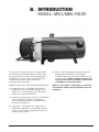
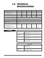
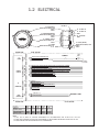
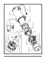
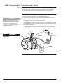
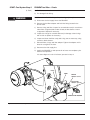
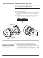
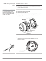
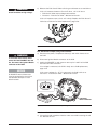
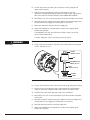
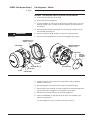
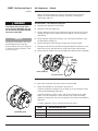
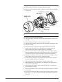
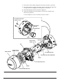
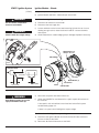
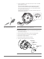
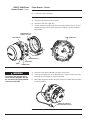
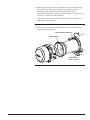
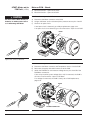
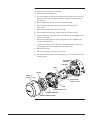
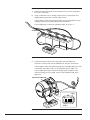
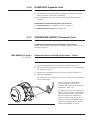
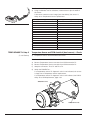
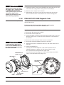
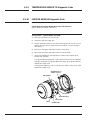
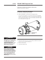
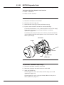
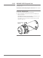
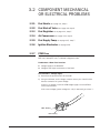
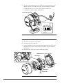
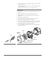
by TELEFLEX
SERVICE MANUAL
M50/M80/M105
CONTENTS
A.
SAFETY .......................................................................................A-1
SAFETY CONSIDERATIONS ..............................................................A-2
B.
INTRODUCTION ..........................................................................B-1
1.0 TECHNICAL SPECIFICATIONS ...................................................1-1
1.1 PHYSICAL ...............................................................................1-2
1.2 ELECTRICAL............................................................................1-3
2.0 PRINCIPLES OF OPERATION ....................................................2-1
2.1 COMPONENT DESCRIPTION .....................................................2-1
2.2 NORMAL OPERATING SEQUENCE..............................................2-4
3.0 TROUBLESHOOTING AND REPAIR ............................................3-1
3.1 SYSTEM AND COMPONENT DIAGNOSTICS.................................3-2
3.1.1 START Diagnostic Code................................................3-3
3.1.2 FLAME OUT Diagnostic Code ......................................3-24
3.1.3 COOLANT FLOW Diagnostic Code ................................3-25
3.1.4 OVERHEAT Diagnostic Code........................................3-27
3.1.5 VOLTAGE Diagnostic Code..........................................3-27
3.1.6 FLAME FAULT Diagnostic Code ...................................3-29
3.1.7 TEMPERATURE SENSOR T1 Diagnostic Code ...............3-29
3.1.8 FUEL SHUT-OFF VALVE Diagnostic Code.......................3-31
3.1.9 TEMPERATURE SENSOR T2 Diagnostic Code ...............3-32
3.1.10 IGNITION MODULE Diagnostic Code ............................3-32
3.1.11 COOLANT PUMP Diagnostic Code................................3-33
3.1.12 MOTOR Diagnostic Code ............................................3-34
3.1.13 AUXILIARY OUTPUT Diagnostic Code ...........................3-35
3.1.14 SWITCH/TIMER POWER Diagnostic Code .....................3-36
3.2 COMPONENT MECHANICAL OR ELECTRICAL PROBLEMS...........3-37
3.2.1 Fuel Nozzle ...............................................................3-37
3.2.2 Fuel Shut-off Valve .....................................................3-37
3.2.3 Fuel Regulator ...........................................................3-37
3.2.4 Air Compressor..........................................................3-37
3.2.5 Fuel Supply Pump ......................................................3-37
3.2.6 Ignition Electrodes .....................................................3-37
3.2.7 PCM Fuse .................................................................3-37
3.3 OPERATIONAL PROBLEMS......................................................3-40
4.0 MAINTENANCE ...........................................................................4-1
5.0 MAINTENANCE TOOLS ..............................................................5-1
A. SAFETY
Throughout this manual, you will see notes labeled DANGER, WARNING,
CAUTION, and NOTICE to alert you to special instructions or precautions
concerning a particular procedure that would be hazardous if performed
incorrectly or carelessly.
Observe them carefully!
These safety alerts alone, cannot eliminate hazards that can occur. Strict
compliance with these special instructions when performing the
installation and maintenance, plus common sense, are major accident
prevention measures.
DANGER
Immediate hazards that will result
in severe injury or death.
WARNING
Hazards or unsafe practices that
could result in severe personal
injury or death.
CAUTION
Hazards or unsafe practices that
could result in minor injury or
product or property damage.
NOTICE
Information that is important to
proper installation or maintenance,
but is not hazard-related.
PROHEAT M-SERIES SERVICE MANUAL
A-1
SAFETY CONSIDERATIONS
WARNING
Exhaust
Inhalation of exhaust gas (containing carbon monoxide) may cause severe personal
injury and/or death. Anyone suspected of suffering from CO inhalation should be
removed from the hazardous area and given medical assistance immediately.
DANGER
California Proposition 65 Warning
Diesel exhaust and some of its constituents are known to the State of California to
cause cancer, birth defects, and other reproductive harm.
Electrical components in this product may contain lead, a chemical known to the
State of California to cause cancer and birth defects and other reproductive harm.
WARNING
Fuel
Exercise extreme caution when working near fuel or fuel-filled equipment. Do not
operate equipment during fueling operations.
WARNING
Batteries
Use eye protection when working near batteries, which contain acid and can explode.
Do not smoke or use open flames near batteries.
WARNING
Electrical
Electric shock can cause severe personal injury, burns, and death. Before working on
any unit, disconnect the batteries. Use only approved materials and methods when
working on the electrical system, and follow local electrical codes. Never work with
electricity in wet conditions or when you are tired.
WARNING
Poisons/Toxins
Fuel and coolant are toxic and in some cases, carcinogenic. Wear eye and hand
protection at all times. Remove contaminated clothing immediately and wash
contaminated skin. Do not breathe in vapors.
WARNING
Hot Parts
Moving parts can cause severe injury and or death. Before working on any unit, shut it
off. Do not operate any unit until protective covers have been replaced. Always ensure
bolts and clamps are correctly torqued and secured. Inspect mechanical components
periodically for damage and corrosion.
WARNING
Coolant
Never remove the filler cap when the engine is hot – escaping steam or scalding water
could cause serious personal injury. The coolant level in the expansion tank should be
checked at least weekly (more frequently in high mileage or arduous conditions). Always
check the level when the system is cold. Unscrew the filler cap slowly, allowing the
pressure to escape before removing completely. Never run the engine without coolant.
Prevent anti-freeze coming in contact with the skin or eyes. If this occurs, rinse
immediately with plenty of water. Anti-freeze will damage painted surfaces.
Never top-up with salt water. Even when travelling in territories where the water supply
contains salt, always ensure you carry a supply of fresh (rain or distilled) water.
A-2
PROHEAT M-SERIES SERVICE MANUAL
B. INTRODUCTION
MODEL: M50/M80/M105
This manual is provided to assist in troubleshooting
and maintaining the PROHEAT M-Series heater. They
are designed for use on any diesel-equipped vehicle
including trucks, buses (school, transit and coach),
construction equipment, off road equipment,
military equipment and cargo.
(4) Marine – Marine applications typically involve the
engineering and installation of a complete
hot-water heating system of which PROHEAT is only
one component. Teleflex recommends that only an
expert in marine hot-water heating systems install
a PROHEAT for marine applications.
PROHEAT heaters are used for the following applications:
NOTE: It is the installer’s responsibility to ensure that
an installation complies with all applicable codes and
regulations.
(1) Engine Block Heat – A PROHEAT will preheat an
engine block to ensure reliable starting in cold
weather. Its’ use throughout the year will reduce
engine wear caused by cold starts.
(2) Supplemental Heat (engine running) – The PROHEAT
can be used while the vehicle is operating to
provide supplemental heat for the engine and/or
passenger compartment.
(3) Cargo Heat – The PROHEAT can supply heat to
individual compartments as a stand-alone heating
system, or it can provide supplemental heat to an
existing heating system.
PROHEAT M-SERIES SERVICE MANUAL
B-1
B-2
PROHEAT M-SERIES SERVICE MANUAL
1.0 TECHNICAL
SPECIFICATIONS
M50 12V
M50 24V
M80 12V
M80 24V
M105 24V
HEAT OUTPUT ± 10% BTU/hr (kW)
50,000 (15)
50,000 (15)
80,000 (23)
80,000 (23)
105,000 (30)
SYSTEM VOLTAGE
Nominal Voltage (Range)
12 (10 – 15)
24 (20 – 30)
12 (10 – 15)
24 (20 – 30)
24 (20 – 30)
CURRENT DRAW Amps
9.5
4.0
8.5
4.0
7.5
FUEL CONSUMPTION US gph (lph)
0.48 (1.8)
0.48 (1.8)
0.78 (2.95)
0.78 (2.95)
1.04 (3.6)
IGNITION TYPE
Electronic Spark Ignition
FUEL TYPES
Diesel, JP8, Jet A1, Arctic
COOLANT OUTPUT TEMPERATURE MAX.
185°F (85°C)
AMBIENT OPERATING TEMPERATURE
-40°F to +122°F (-40°C to +50°C)
WEIGHT lbs (kg)
53 (23.5)
HEAT EXCHANGER CAPACITY US gal (l)
0.5 (2)
COOLANT SYSTEM
Minimum Capacity US gal (l)
2.64 (10)
2.64 (10)
2.64 (10)
2.64 (10)
2.64 (10)
Recommended Flow Rate Through
Heater US gpm (lpm)
5 (19)
5 (19)
7 (26.5)
7 (26.5)
9 (34)
DANGER
Do not use gasoline.
SYSTEM OUTPUTS
AUXILIARY OUTPUT
Same as System Voltage
Maximum 1 Amp draw (over-load shut-off protection)
High-side switched
SWITCH/TIMER
POWER
Same as System Voltage
Maximum 1 Amp draw (over-load shut-off protection)
High-side switched
COOLANT PUMP
Same as System Voltage
Maximum 10 Amp draw (over-load shut-off protection)
High-side switched
INDICATOR LIGHT
Same as System Voltage
Maximum 1 Amp draw (over-load shut-off protection)
High-side switched
SYSTEM INPUTS
PROHEAT M-SERIES SERVICE MANUAL
SWITCH
10 – 30V
Standard Run Mode
Preheat Run Mode
Supplemental Run Mode
COOLANT PUMP
AUXILIARY
10 – 30V
Allows independent operation of Coolant Pump through
the Proheat Control Module
1-1
1.1 PHYSICAL
INLET
9.55 (243)
1.97 (50)
THE INLET AND OUTLET CAN
BE REVERSED WITH THE
ADDITION OF A SECONDARY
TEMPERATURE SENSOR
OUTLET
2X
1.50 (38)
TOP VIEW
SERVICE SPACE
REQUIREMENT
(SEE NOTE 3)
9.53 (242)
23.30 (592)
5.77
(147)
9.00 (229)
-4 JIC MALE FUEL INLET
(INTERNAL FUEL FILTER)
8.61
(219)
4.45
(113)
PCM
FRONT VIEW
1.40 (36)
2.13 (54)
3.94
(100)
7.63
(194)
5.37
(136)
EXHAUST (SEE NOTE 4)
4.93
(125)
.75 (19)
SIDE VIEW
REAR VIEW
8.20 (208)
12.60 (320)
3.23
(82)
Ø2.75 (70)
4X M8X1.25
MOUNTING PEM NUTS
4.33 5.90
(110) (150)
6X
Ø.41 (10)
BOTTOM VIEW
NOTES:
1. DIMENSIONS ARE IN INCHES (MILLIMETERS IN BRACKETS).
2. TYPICAL EXHAUST CUTOUT 3.25" CENTERED ON EXHAUST.
3. SERVICE SPACE REQUIRED TO REMOVE BURNER HEAD AND COMBUSTION TUBE FOR PERIODIC
INSPECTION AND CLEANING.
4. THE EXHAUST PIPE SHOULD HAVE A MINIMUM DIAMETER OF 2.75", A MAXIMUM LENGTH OF 5'
AND HAVE NO MORE THAN 180 DEGREES OF BENDS.
1-2
PROHEAT M-SERIES SERVICE MANUAL
1.2 ELECTRICAL
P5 - AUX (OUTPUT)
METRI-PACK 150 SERIES, 2 PIN
NOTE 1
NOTE 3
PROHEAT PCM
P8 - T1: TEMP SENSOR
P7 - T2: TEMP SENSOR
NOTE 3
P3 - DATALINK (DOWNLOAD)
METRI-PACK 150 SERIES, 6 PIN
NOTE 1
NOTE 3
P6 - FUTURE USE
NOTE 3
P2 - CONTROL (SWITCH)
METRI-PACK 150 SERIES, 8 PIN
NOTE 1
P4 - PUMP (COOLANT)
METRI-PACK 150 SERIES, 2 PIN
NOTE 1
NOTE 3
P1 - POWER
METRI-PACK 280 SERIES, 2 PIN
NOTE 2
PROHEAT PCM
O.E.M. SUPPLIED
POWER
SUPPLY
RECOMMENDED
25 AMP FUSE
P1
POWER
A
B
A
B
( )
(+)
BATTERY POSITIVE ((FUSE/BREAKER 30 AMP))
(-)
BATTERY NEGATIVE (GROUND)
(
)
VEHICLE
GROUND
P2
CONTROL
(SWITCH)
P3
DATALINK
(DOWNLOAD)
P4
PUMP
(COOLANT)
A
B
A
B
INDICATOR OUTPUT ((HIGH SIDE SWITCHED. DASH OR PROHEAT TOGGLE SWITCH LIGHT)) ((1 AMP MAX))
D
D
GROUND ((ACCESSORY OUTPUT GROUND)) ((1 AMP MAX))
F
F
PREHEAT SWITCH INPUT ((ACTIVE HIGH 10 TO 30 VOLTS))
H
H
PUMP ((COOLANT)) SWITCH INPUT (ACTIVE
(
HIGH 10 TO 30 VOLTS))
A
B
C
D
E
F
A
B
C
D
E
F
RS232 Rx
A
B
A
B
COOLANT PUMP OUTPUT
GROUND ((INDICATOR GROUND)) ((1 AMP MAX))
POWER OUTPUT ((CONSTANT POWER. TIMER/SWITCH REMOTE PANEL)) ((1 AMP MAX SHARED WITH P3-D))
MAIN SWITCH INPUT ((STANDARD "ON" SIGNAL OR PREHEAT UNLATCH)) ((ACTIVE HIGH 10 TO 30 VOLTS))
SUPPLEMENTAL SWITCH INPUT ((ACTIVE HIGH 10 TO 30 VOLTS))
GROUND ((1 AMP MAX))
INDICATOR OUTPUT ((1 AMP MAX))
ACCESSORY POWER OUTPUT ((1 AMP MAX SHARED WITH P2-C))
RS232 Tx
FACTORY USE (N/A)
( )
MAXIMUM 10 AMPS
COOLANT PUMP GROUND
PROHEAT PCM
PCM
CONNECTOR
O.E.M. SUPPLIED
CONNECTOR
PART#
LOCK
PART#
TERMINAL
PART#
WIRE SEAL
PART#
P1-POWER
15300027
15300014
12077413
12015193
P2-CONTROL (SWITCH)
12047937
12066304
12048074
12048086
12059168
12048074
12048086
12059168
12052641
12052634
12048074
12048086
12059168
P3-DATALINK (DOWNLOAD)
P4-PUMP (COOLANT)
CAVITY SEAL
PART#
----
NOTES:
1/ 150 SERIES CONNECTOR ASSEMBLIES TO BE USED WITH 18AWG WIRE WITH MAXIMUM .1" INSULATION DIAMETER. WIRE MUST MEET OR EXCEED SAE J1128 GPT SPECIFICATIONS.
2/ 280 SERIES CONNECTOR ASSEMBLIES TO BE USED WITH 10AWG WIRE WITH MAXIMUM .161" INSULATION DIAMETER. WIRE MUST MEET OR EXCEED SAE J1128 GPT OR GXL.
3/ ALL UNUSED CONNECTIONS ON THE PCM ARE SUPPLIED WITH SEAL PLUGS ON STANDARD HEATERS.
PROHEAT M-SERIES SERVICE MANUAL
1-3
1-4
PROHEAT M-SERIES SERVICE MANUAL
2.0 PRINCIPLE OF
OPERATION
2.1 COMPONENT DESCRIPTIONS
Combustion Air Blower:
Motor:
Fuel Supply Pump:
Fuel Regulator:
Fuel Nozzle:
Fuel Shut-off Valve:
Impeller-style blower driven by the Motor provides the principle combustion air.
Drives the Combustion Air Blower, Air Compressor and Fuel Supply Pump.
A positive displacement, gear-type pump that draws fuel from the vehicle fuel
tank and supplies it to the Fuel Regulator. Pressure is regulated between
7 – 10 PSI by means of an internal relief valve. Fuel is re-circulated within the
pump, therefore a fuel return line to the tank is not required.
Diaphragm-type pressure reducing valve. The Fuel Regulator drops the fuel
supply pressure to atmospheric pressure (0 PSI).
Air-aspirating type burner nozzle. Compressed air flows through the air
passages, exiting the nozzle in front of the fuel orifice creating a vacuum in
the fuel supply. This draws fuel from the Fuel Regulator and the combined
fuel/air mixture is atomized into the combustion chamber.
Electrically operated solenoid valve which controls fuel flow to the Fuel Nozzle.
Air Compressor:
Rotary vane compressor that supplies air pressure (in the range of 3 – 5 PSI)
to the Fuel Nozzle.
Ignition Module:
Electronic Ignition Module with plug-in electrode.
PCM:
(PROHEAT Control Module)
Combustion Tube:
PROHEAT M-SERIES SERVICE MANUAL
Electronic control module monitors the PROHEAT sensors, operating conditions,
and controls the Motor and other devices. Diagnostics are utilized for both
safety in operations and detection of component faults to aid in service and
troubleshooting. The PCM contains the flame sensor which senses the flame
intensity. This information can be retrieved by a personal computer using
PROHEAT Datalink software.
Directs the air supplied by the blower through a swirler into the combustion
zone, mixing it with the atomized fuel/air mixture from the Fuel Nozzle.
2-1
Heat Exchanger:
Temperature Sensor 1:
Measures the coolant temperature near the outlet port of the heat exchanger
and sends this information to the PCM. It must be connected at all times
for overheat protection.
Temperature Sensor 2:
For installations where the coolant flow through the heat exchanger is
opposite of what is specified on page 1-2. This sensor also measures the
inner heat exchanger surface temperature for an overheat condition.
Coolant Pump:
2-2
Coolant is circulated through the heat exchanger via the inlet and outlet
ports. Heat is transferred from the heat exchanger through the inner wall of
the exchanger into the coolant. The exhaust gases are directed out through
the exhaust port.
Circulates coolant through the PROHEAT and vehicle heating system.
Depending on the PROHEAT installation, it may be operated by the PCM.
PROHEAT M-SERIES SERVICE MANUAL
PROHEAT M-SERIES SERVICE MANUAL
2-3
BLOWER HOUSING
AIR COMPRESSOR
FUEL
SHUT-OFF
VALVE
AIR FILTER
IGNITION
ELECTRODES
PCM (PROHEAT CONTROL MODULE)
COMBUSTION AIR BLOWER
FUEL
SUPPLY
PUMP
FUEL
NOZZLE
IGNITION MODULE
FUEL REGULATOR
MOTOR
BURNER HEAD FLANGE
TEMPERATURE
SENSOR 2
(IF EQUIPPED)
COMBUSTION TUBE
TEMPERATURE SENSOR 1
HEAT EXCHANGER
2.2 NORMAL OPERATING
SEQUENCE
1. . . . . . . . . . . . . . . . Switch On:
If the coolant temperature is below 160°F (71°C) the PROHEAT enters
Pre-check. If the coolant temperature is above 160°F (71°C) the PROHEAT
enters Standby.
2. . . . . . . . . . . . . . . . Pre-check:
The PCM performs self diagnosis checking sensors for correct range and
electrical components for over-load. Also during the first Pre-check, the Ignition
Module is powered for five seconds to allow a service technician to visually
check for a spark.
3. . . . . . . . . . . . . . . . . . Ignition:
The Motor and Coolant Pump start first, followed by the ignition spark, and
Fuel Shut-off Valve. The Ignition Module sparks for 30 seconds during which
time the flame sensor must detect correct combustion.
4. . . . . . . . Combustion Check:
At the end of the Ignition cycle the Flame Sensor checks the combustion. If
acceptable, the PROHEAT enters Full Output. If not acceptable, the PROHEAT
goes to Cool Down and then will start again at Pre-check. If the second start
cycle fails the PROHEAT will enter Fault Shut Down.
5. . . . . . . . . . . . . . . Full Output:
The PROHEAT will continue in Full Output until the coolant temperature
reaches 185°F (85°C) at the PROHEAT outlet Temperature Sensor.
6. . . . . . . . . . . . . . . Cool Down:
The Motor and Coolant Pump continue to operate for up to three minutes, the
Motor stops and the PROHEAT enters Standby. The PROHEAT will Cool Down
for three reasons:
• Coolant reaches 185°F (85°C).
• A fault is detected. Go to Troubleshooting and Repair
• The PROHEAT is operating in Ignition or Full Output when it is switched off.
7. . . . . . . . . . . . . . . . . . Standby:
The Coolant Pump continues to circulate coolant throughout the system (go
to Auxiliary Input Section for alternative operating modes). When the coolant
temperature drops to its cycle on temperature, the PCM will repeat the cycle
starting at Pre-check.
8. . . . . . . . . . . . . . . . Switch Off:
If the PROHEAT is in Ignition or Full Output, it will Cool Down first, then shut OFF.
If the PROHEAT is in Standby, it will shut OFF immediately.
9. . . . . . . . . . Fault Shut Down:
If the PROHEAT diagnostics sense a system or component fault, the PROHEAT will
shut down all components and flash a fault code(s) which best represents the
conditions. To reset the PROHEAT, it must be switched off and then on again.
NOTE: Damage may occur it the fault codes are ignored and the PROHEAT is
repeatedly switched off and on without addressing the problem.
2-4
PROHEAT M-SERIES SERVICE MANUAL
3.0 TROUBLESHOOTING
AND REPAIR
Problems with the PROHEAT and its operation will be indicated in two ways:
1. PROHEAT Diagnostic Faults indicated by means of a flashing diagnostic
code on an indicator light (if equipped). Go to page 3-2.
2. Operational problems may not be identified with a flashing diagnostic code
(e.g., blown fuse, obstructed coolant flow, air leaks in fuel supply line).
Go to page 3-40.
Troubleshooting a Problem
STEP 1
Locate the PROHEAT, remove the enclosure lid if used and visually check for
any problems with wiring harnesses, fuel leaks, coolant leaks, exhaust pipe
damage and environmental condition.
STEP 2
If equipped with a diagnostic indicator light, and it is flashing, determine the
code based on page 3-2.
STEP 3
If no code is indicated, turn the PROHEAT off and then on again using the
existing operational switches, timer or a PROHEAT remote start switch
(PROHEAT P/N PK0091).
STEP 4
Let the PROHEAT attempt to start and/or operate. Observe the operation.
NOTE: The PROHEAT will always attempt to start twice, as long as the
coolant temperature is below 160°F (71°C). If a fault is detected it will shut
down, go through a Cool Down and attempt a second start. After both
attempts to start or operate, an indicator light will flash a diagnostic code.
Go to page 3-2.
• If the indicator light flashes, count the number of flashes and refer to
the troubleshooting diagnostic code description for that number on the
following pages.
• If the PROHEAT runs but is not performing or operating correctly, consult
the Operational Problems section, page 3-40.
Troubleshooting and Repair Tools Required
• Remote Start Switch (PROHEAT P/N PK0091)
Allows the service technician to work at the PROHEAT. Isolates the
PROHEAT from the existing vehicle system controls and comes with a
built-in indicator light.
• Temperature Sensor (PROHEAT P/N 200301K)
Allows the service technician to start a PROHEAT when the coolant
temperature is greater than 160°F (71°C). To be used only for
troubleshooting.
PROHEAT M-SERIES SERVICE MANUAL
3-1
3.1 SYSTEM AND COMPONENT
DIAGNOSTICS
The PCM continually monitors the PROHEAT operating conditions. If the PCM
detects a problem, the indicator light flashes a diagnostic code(s).
The diagnostic indicator light may be located:
• In the toggle of the ON/OFF Switch provided by PROHEAT (standard
installation kit).
• In the PROHEAT Timer manual ON light (red).
• In an OEM indicator light package.
• In the remote switch (PROHEAT P/N PK0091) used for troubleshooting.
NO. OF FLASHES
SYSTEM
DIAGNOSTICS
COMPONENT
DIAGNOSTICS
3-2
DIAGNOSTIC CODE DESCRIPTION
PAGE
1
Start
3-3
2
Flame Out
3-24
3
Coolant Flow
3-25
4
Overheat
3-27
5
Voltage
3-27
6
Flame Fault
3-29
7
Temperature Sensor T1
3-29
8
Fuel Shut-off Valve
3-31
9
Temperature Sensor T2
3-32
10
Ignition Module
3-32
11
Coolant Pump
3-33
12
Motor
3-34
13
Auxiliary Output
3-35
14
Switch Output
3-36
PROHEAT M-SERIES SERVICE MANUAL
3.1.1
(1 Flash)
START Diagnostic Code
Indicates that the PCM Flame Sensor did not detect a flame or the flame was
too weak to be detected during the FULL ignition period (M50/M80/M105 –
30 second ignition period).
Troubleshoot the Start diagnostic code based on the following symptoms:
1. Fuel System. Go to page 3-4 to 3-15, Steps 1 through 7.
a) There is no fuel, fuel odor or atomized fuel coming from the exhaust pipe.
b) There is no hot exhaust coming from the exhaust pipe.
2. Ignition System. Go to page 3-18.
a) There is raw fuel and/or atomized fuel and a raw fuel odor coming
from the exhaust pipe.
b) There is no hot exhaust coming from the exhaust pipe.
3. PCM (PROHEAT Control Module) Flame Sensor circuit. Go to page 3-20.
a) There is a flame and the combustion sounds good, the PROHEAT
appears to be operating normally.
b) No smoke, raw fuel odor or atomized fuel is coming from the
exhaust pipe.
4. Motor and/or PCM fault. Go to page 3-22.
a) The Motor is NOT running. Ignition and Coolant Pump are operating.
b) No smoke, raw fuel odor or atomized fuel coming from the exhaust pipe.
PROHEAT M-SERIES SERVICE MANUAL
3-3
START: Fuel System Step 1
(1 Flash)
Fuel and fuel supply – Check:
a) Vehicle fuel level and/or for fuel gelling during cold weather.
b) Air leaks and/or restrictions in the fuel supply lines to the PROHEAT.
c)
The PROHEAT operation when supplying fuel from a direct source.
Test Procedure – Supplying fuel from a remote source:
a) Remove the fuel supply line from the PROHEAT fuel inlet.
NOTICE
When fuel system is open, the
PROHEAT will smoke and stumble
until the air is purged from the
system. It may be required to cycle
more than one time.
b) Using a length of fuel line connected from the PROHEAT fuel inlet to a
direct source of CLEAN fuel. Switch the PROHEAT on and operate for at
least one complete cycle. Observe the operation.
If the PROHEAT functions correctly, the fault is in the vehicle fuel system.
Check fuel lines, connections and routing back to fuel tank. Consult OEM
for service requirements.
If a Start diagnostic code is indicated, the problem is in the PROHEAT
fuel system. Proceed to Step 2.
WARNING
FUEL INLET
Flammable.
FUEL
CONTAINER
Figure 3-1: Remote Fuel Supply
3-4
PROHEAT M-SERIES SERVICE MANUAL
START: Fuel System Step 2
(1 Flash)
PROHEAT fuel filter – Check:
a) For filter contamination and restrictions.
b) For damaged inlet fitting.
WARNING
Flammable.
Test Procedure – Fuel filter inspection, cleaning and/or replacement:
a) Disconnect the fuel supply line at the PROHEAT.
b) Remove the fuel filter adapter and fuel inlet fitting located in the
burner head.
c)
Remove O-ring and filter. Inspect for contamination and/or restrictions.
Clean filter using electrical contact cleaner, brake cleaner or warm
soapy water. Replace if necessary.
d) Inspect the O-rings for contamination and/or damage. Clean O-rings
with a cloth or replace as necessary.
e) Inspect and clean the filter cavity and O-ring seat as necessary using
contact or brake cleaner.
f)
Reinstall filter, O-rings and inlet adapter. Tighten the adapter until it
bottoms out against the face.
g)
Reconnect the fuel supply line.
h) Switch the PROHEAT on and operate for at least one complete cycle.
Observe the operation.
If a Start diagnostic code is indicated, proceed to Step 3.
FILTER
O-RING
ADAPTER
TORQUE = 50 in-lbs
INLET FITTING
TORQUE = 100 in-lbs
THREAD SEALANT REQUIRED
Figure 3-2: Fuel Filter Assembly and Location
PROHEAT M-SERIES SERVICE MANUAL
3-5
START: Fuel System Step 3
(1 Flash)
Fuel Nozzle and Fuel Nozzle cavity – Check:
a) For Fuel Nozzle and O-ring damage and/or contamination.
b) For correct Fuel Nozzle for the PROHEAT BTU rating.
Test Procedure – Fuel Nozzle removal, inspection and cleaning or replacement:
a) Disconnect all harnesses at the PCM.
b) Disconnect the fuel supply line.
c)
Loosen and back out the burner head mounting (2) bolts five to six turns
allowing enough room to rotate the burner head 15° counter-clockwise
and remove.
d) Remove Fuel Nozzle. Verify the Fuel Nozzle number ensuring it is the
correct Fuel Nozzle for your PROHEAT model. See table below.
MODEL
NUMBER
M50
30609-50
M80
30609-9
M105
30609-11
MOUNTING BOLTS (2)
TORQUE = 100 in-lbs
TEMP SENSOR 1
FUEL NOZZLE
TORQUE = 100 in-lbs
FUEL INLET
FUEL NOZZLE CAVITY
SWITCH INPUT
POWER
COOLANT PUMP
Figure 3-3: Burner Head Removal and Fuel Nozzle Removal
e) Disassemble, inspect, clean, and reassemble Fuel Nozzle.
NOTICE
Fuel Nozzle parts are a matched set
and not interchangeable.
3-6
Fuel Nozzle disassembly, inspection, cleaning and reassembly:
• Hold the Fuel Nozzle stem lightly but firmly in a vise, take care not to
cause damage. Disassembles in three pieces.
• Inspect Fuel Nozzle stem and O-ring for contamination and/or damage.
Inspect and clean distributor fuel orifice, air passages, head and stem
with electrical contact cleaner, brake cleaner or warm soapy water.
PROHEAT M-SERIES SERVICE MANUAL
• Re-clamp the Fuel Nozzle stem lightly but firmly in a vise, take care
not to cause damage. Reinstall the distributor and Fuel Nozzle head.
Ensure that the distributor is seated correctly. The Fuel Nozzle
assembly is self-aligning.
DISTRIBUTOR
HEAD
NOZZLE
NUMBER
STEM
O RING
AIR PASSAGES
FUEL AND AIR
OUTLET ORIFICE
FUEL NOZZLE ORIFICE
ASSEMBLY TORQUE = 30 in-lbs
Figure 3-4: Fuel Nozzle Assembly
f)
Inspect the Fuel Nozzle cavity and clean as necessary using electrical
contact cleaner or brake cleaner.
g)
Reinstall the Fuel Nozzle.
h) Reinstall the burner head by mounting it against the heat exchanger face,
turning clockwise to engage the mounting ears on the bolts.
i)
Tighten mounting bolts.
j)
Reconnect the electrical harnesses and fuel supply line.
k)
Switch the PROHEAT on and operate for at least one complete cycle.
Observe the operation.
If a Start diagnostic code is indicated, proceed to Step 4.
PROHEAT M-SERIES SERVICE MANUAL
3-7
START: Fuel System Step 4
(1 Flash)
Fuel Shut-off Valve – Check:
a) Fuel Shut-off Valve and PCM - electrical open circuit fault.
b) Valve plunger – mechanical fault. Test the PROHEAT operation; Fuel
Shut-off Valve plunger removed.
NOTICE
It is recommended that the Fuel
Regulator be serviced at the same
time as the Fuel Shut-off Valve. Go
to page 3-11, Step 5.
Procedure – Coil and PCM – electrical fault:
a) Disconnect all harnesses at the PCM.
b) Disconnect the fuel supply line.
c)
Loosen and back out the burner head mounting (2) bolts five to six turns
allowing enough room to rotate the burner head 15° counter-clockwise
and remove.
MOUNTING BOLTS (2)
TORQUE = 100 in-lbs
TEMP SENSOR 1
FUEL INLET
MOUNTING EARS (2)
SWITCH INPUT
POWER
COOLANT PUMP
Figure 3-5: Burner Head Removal
d) Remove the Fuel Shut-off Valve connector. Use a small flat head
screwdriver to lift the connector locking tab, pulling up on the
connector to remove.
LOCK
PCM FUEL SHUT-OFF
VALVE CONNECTION
Figure 3-6: Connector Removal
3-8
Figure 3-7: PCM Fuel Shut-off Valve Connection
PROHEAT M-SERIES SERVICE MANUAL
WARNING
e) Measure the Fuel Shut-off Valve coil using a multimeter set to read Ohms.
If the coil measures between 35 and 45 Ohms, coil is OK. Go to:
• Fuel Shut-off Valve output voltage measurement.
• Procedure – Fuel Shut-off Valve – Mechanical function.
Shock hazard due to high voltage.
If the coil measures open circuit, coil is faulty. Replace the Fuel Shut-off
Valve. Go to Fuel Shut-off Valve replacement, page 3-10.
Figure 3-8: Coil Electrical Resistance Measurement
Fuel Shut-off Valve output voltage measurement:
WARNING
To avoid the risk of shock and to
ensure that the PROHEAT does not
fire, disconnect the Ignition Module
connector at the PCM.
a) Reconnect the power, Temperature Sensor(s) and switch harnesses at
the PCM.
b) Disconnect Ignition Module connector at the PCM.
c)
Switch the PROHEAT on and measure across pins A and B of the PCM
Fuel Shut-off Valve connection.
If no voltage is measured, the PCM is faulty. Go to PCM replacement,
page 3-39.
NOTICE
All PROHEAT external harnesses
must be connected to ensure that
the PROHEAT attempts to start
after Pre-check.
If the correct voltage (9 – 15 V) is measured, the PCM is OK. Go to
Procedure – Fuel Shut-off Valve – Mechanical function.
A
B
PCM IGNITION
MODULE CONNECTION
Figure 3-9: PCM Fuel Shut-off Valve Output Voltage Measurement
Procedure – Fuel Shut-off Valve – Mechanical function:
a) Using a flat head screwdriver hold the valve stem while loosening the coil
nut. Remove the coil.
PROHEAT M-SERIES SERVICE MANUAL
3-9
b) Loosen and remove the valve stem. Remove the O-ring, plunger and
spring. Save the parts.
c)
Inspect the O-ring and plunger seat for contamination. Clean as
necessary using electrical contact cleaner or brake cleaner. Reinstall the
valve stem and seal. DO NOT INSTALL THE PLUNGER AND SPRING.
d) Reinstall the coil, coil nut and reconnect the Fuel Shut-off Valve to the PCM.
e) Reinstall the burner head by mounting it against the heat exchanger face,
turning clockwise to engage the mounting ears on the bolts.
f)
Reconnect electrical harnesses and fuel supply line.
g)
Switch the PROHEAT on and operate for at least one complete cycle.
Observe the operation.
If the PROHEAT runs OK, the Fuel Shut-off Valve is faulty. Go to Fuel
Shut-off Valve replacement.
If a Start diagnostic code is indicated, proceed to Step 5.
WARNING
Flammable.
Fuel Shut-off Valve replacement:
a) Using a flat head screwdriver, hold the stem in place while loosening the
coil nut. Remove the coil.
COIL NUT
TORQUE = 25 in-lbs
COIL
SCREWDRIVER SLOT
TORQUE = 25 in-lbs
STEM
TORQUE = 25 in-lbs
PLUNGER
O-RING
Figure 3-10: Fuel Shut-Off Valve Assembly
b) Loosen and remove the valve stem. Remove the O-ring, plunger and spring.
c)
Inspect the O-ring and plunger seat in the fuel block for contamination.
Clean as necessary using electrical contact cleaner or brake cleaner.
d) Install the new valve stem and seal using a slot screwdriver.
e) Reinstall the coil, coil nut and reconnect the Fuel Shut-off Valve connector
at the PCM.
f)
Reinstall the burner head by mounting it against the heat exchanger face,
turning clockwise to engage the mounting ears on the bolts.
g)
Reinstall electrical harnesses and fuel supply line.
h) Switch the PROHEAT on and operate for at least one complete cycle.
Observe the operation.
3-10
PROHEAT M-SERIES SERVICE MANUAL
START: Fuel System Step 5
(1 Flash)
Fuel Regulator – Check:
a) For damage and/or contamination and mechanical operation.
Procedure – Fuel Regulator removal, inspection and reinstallation:
a) Disconnect all harnesses at the PCM.
b) Disconnect the fuel supply line.
c)
Loosen and back out the burner head mounting (2) bolts five to six turns
allowing enough room to rotate the burner head 15° counter-clockwise
and remove.
d) Remove ignition electrode assembly. Use a flat head screwdriver to pry
the electrode assembly out.
WARNING
e) Remove the flame shield. Rotate to match the mounting square.
f)
Flammable.
Remove the Fuel Regulator (2) screws, Fuel Regulator and O-rings.
MOUNTING BOLTS (2)
TORQUE = 100 in-lbs
TEMP SENSOR 1
MOUNTING SCREWS (2)
TORQUE = 50 in-lbs
FLAME SHIELD
IGNITION
ELECTRODE
ASSEMBLY
FUEL INLET
MOUNTING EARS (2)
FUEL REGULATOR
SWITCH INPUT
POWER
COOLANT PUMP
Figure 3-11: Burner Head Removal and Fuel Regulator Removal
g)
Inspect O-rings and O-ring seats for contamination and/or damage.
Replace if necessary.
h) Reinstall regulator ensuring that the O-rings are seated properly.
i)
Reinstall the burner head by mounting it against the heat exchanger face,
turning clockwise to engage the mounting ears on the bolts.
j)
Reconnect the electrical harnesses and fuel supply line.
k)
Switch the PROHEAT on and operate for at least one complete cycle.
Observe the operation.
If a Start diagnostic code is indicated, proceed to Step 6.
PROHEAT M-SERIES SERVICE MANUAL
3-11
START: Fuel System Step 6
(1 Flash)
Air Compressor – Check:
a) Air Compressor pressure and operation.
Before checking air pressure, remove, disassemble and clean Fuel
Nozzle. Go to Fuel Nozzle disassembly, inspection, cleaning and
reassembly, page 3-6.
WARNING
To avoid the risk of shock and to
ensure that the PROHEAT does not
fire, disconnect the Ignition Module
connector at the PCM.
NOTICE
Leaving the Temperature Sensor(s)
disconnected ensures that the
burner head will only run in purge for
a maximum of three minutes. It will
not try to fire up.
Test Procedure – Air Compressor pressure:
a) Disconnect all harnesses at the PCM.
b) Disconnect the fuel supply line.
c)
Loosen and back out the burner head mounting (2) bolts five to six turns
allowing enough room to rotate the burner head 15° counter-clockwise
and remove.
d) Remove ignition electrode assembly. Use a flat head screwdriver to pry
the electrode assembly out.
e) Remove the flame shield. Rotate to match the mounting square.
f)
Disconnect the Fuel Shut-off Valve and Ignition Module connectors at the
PCM. This ensures that fuel will not spray and/or light during testing.
g)
Remove the Air Compressor test port plug and install pressure test gauge.
FLAME SHIELD
IGNITION
ELECTRODE
ASSEMBLY
GAUGE (P/N PK0067)
TEST PORT LOCATION
Figure 3-12: Air Pressure Test
h) Reconnect the power and switch harnesses at the PCM.
i)
Switch the PROHEAT on and read the air pressure:
If the Air Compressor reading is out of range, go to Air Compressor filter
check before attempting adjustment.
If the Air Compressor filter is clean, adjust the PSI ouput as per table
below. If the Air Compressor cannot be set to the correct PSI output,
replace Air Compressor. Go to Air Compressor removal and reinstallation,
page 3-13.
If a Start diagnostic code is indicated, proceed to Step 7.
ADJUSTMENT SCREW
Figure 3-13: Air Compressor Adjustment
3-12
MODEL
AIR PRESSURE BAR (PSI)
M50
0.42 ± 0.01 bar (6.2 ± 0.2 PSI)
M80
0.22 ± 0.01 bar (3.2 ± 0.2 PSI)
M105
0.26 ± 0.01 bar (3.8 ± 0.2 PSI)
PROHEAT M-SERIES SERVICE MANUAL
Air Compressor filter check:
a) Remove blower housing (2) screws and blower housing.
b) Remove the Air Compressor filter. Inspect for contamination and replace
if necessary.
MOUNTING BOLTS (2) TORQUE = 100 in-lbs
TEMP SENSOR 1
HOUSING SCREWS
TORQUE = 75 in-lbs
FUEL INLET
SWITCH INPUT
AIR FILTER
COOLANT PUMP
POWER
Figure 3-14: Burner Head and Blower Housing Removal
Air Compressor removal and reinstallation:
a) Disconnect Motor, Fuel Shut-off Valve and Ignition Module connectors at
the PCM.
b) Remove blower housing (2) screws and blower housing.
c)
Remove blower retaining snap ring and slide the blower off the Motor shaft.
d) Remove the PCM.
e) Remove Motor (4) screws and slide the Motor shaft out of the Fuel
Supply Pump taking care not to damage the Fuel Supply Pump seal.
Note the Motor drive gear size and location for reassembly.
f)
Remove the Air Compressor gear retaining snap ring and gear. Inspect
gears and replace if necessary. If gears are worn out it is not necessary
to replace compressor (spin and check for mechanical interference).
g)
Remove Air Compressor (2) screws, Air Compressor, (2) O-rings and the
gear locating snap ring from the Air Compressor shaft.
h) Install new Air Compressor; ensure that the O-ring and seats are clean
and dry. Assembly lubricant not required.
i)
Reinstall gear locating snap ring, gear and gear retaining ring.
j)
Reinstall the Motor, with drive gear, take care to ensure that the Fuel
Pump seal is not damaged.
k)
Reinstall the PCM, blower, blower retaining snap ring, Air Compressor
filter and blower housing.
l)
Reconnect the Motor, Fuel Shut-off Valve and Ignition Module connectors
at the PCM.
m) Test the Air Compressor. Adjust if necessary to correct pressure setting.
Go to items 'i', 'j' and 'k' in Test Procedure – Air Compressor pressure,
page 3-12.
PROHEAT M-SERIES SERVICE MANUAL
3-13
n) Reinstall the flame shield and ignition electrode assembly to the PCM.
o) Reinstall the burner head by mounting it against the heat exchanger face,
turning clockwise to engage the mounting ears on the bolts.
p) Reinstall electrical harnesses and fuel supply line.
q) Switch the PROHEAT on and operate for at least one complete cycle.
Observe the operation.
If a Start diagnostic code is indicated, proceed to Step 7.
AIR COMPRESSOR SCREWS
TORQUE = 75 in-lbs
GEAR LOCATING
SNAP RING
AIR COMPRESSOR
O-RING
DRIVE GEAR
MOTOR SCREWS
TORQUE = 75 in-lbs
PCM
HOUSING SCREWS
TORQUE = 75 in-lbs
BLOWER HOUSING
AIR COMPRESSOR GEAR
AIR COMPRESSOR GEAR RETAINING RING
MOTOR
AIR COMPRESSOR FILTER
BLOWER
BLOWER RETAINING SNAP RING
Figure 3-15: Air Compressor Replacement
3-14
PROHEAT M-SERIES SERVICE MANUAL
START: Fuel System Step 7
(1 Flash)
Fuel Supply Pump – Check:
a) Fuel Supply Pump pressure and operation.
Test Procedure – Fuel Supply Pump pressure:
a) Disconnect all harnesses at the PCM.
b) Disconnect the fuel supply line.
c)
Loosen and back out the burner head mounting (2) bolts five to six turns
allowing enough room to rotate the burner head 15° counter-clockwise
and remove.
d) Remove ignition electrode assembly. Use a flat head screwdriver to pry
the electrode assembly out.
e) Remove the flame shield. Rotate to match the mounting square.
MOUNTING BOLTS (2)
TORQUE = 100 in-lbs
TEMP SENSOR 1
FLAME SHIELD
IGNITION
ELECTRODE
ASSEMBLY
FUEL INLET
GAUGE (P/N PK0067)
MOUNTING EARS (2)
FUEL SUPPLY PUMP TEST PORT
SWITCH INPUT
POWER
FUEL
SHUT-OFF
SOLENOID
COOLANT PUMP
Figure 3-16: Burner Head Removal and Fuel Pressure Test
WARNING
Flammable.
f)
Disconnect the Fuel Shut-off Valve and Ignition Module connectors at the
PCM. Ensures that fuel will not spray and/or light during testing.
g)
Remove the Fuel Supply Pump test port plug and install test gauge.
h) Reconnect the power and switch harnesses at the PCM.
WARNING
To avoid the risk of shock and to
ensure that the PROHEAT does not
fire, disconnect the Ignition Module
connector at the PCM.
i)
Reconnect the fuel supply line.
j)
Switch the PROHEAT on and read the fuel pressure (should be 3 – 12 PSI):
If the pressure is out of range, Go to Fuel Supply Pump cleaning, page 3-16.
If the pressure reads OK, review Fuel System troubleshooting, page 3-3.
NOTICE
Leaving the Temperature Sensor(s)
disconnected ensures that the burner
head will enter purge mode and run
for a maximum of three minutes.
PROHEAT M-SERIES SERVICE MANUAL
3-15
Fuel Supply Pump cleaning:
a) Disconnect all harnesses at the PCM.
b) Disconnect the fuel supply line.
c)
PRESSURE RELIEF VALVE CAP
TORQUE = 25 in-lbs
BALL BEARING
Loosen and back out the burner head mounting (2) bolts five to six turns
allowing enough room to rotate the burner head 15° counter-clockwise
and remove.
d) Locate the pressure relief valve cap and remove with a slot screwdriver.
Careful not to lose any of the internal components that may fall out.
e) Remove the spring from the cavity.
SPRING
BALL GUIDE
Figure 3-17: Pressure Relief Valve Cap
f)
Remove the ball bearing from the cavity.
g)
Inspect and clean all components.
h) Inspect and clean the cavity. Pay close attention to the center hole in the
cavity for any debris or a damaged edge. The edge of the hole should be
smooth with no nicks, do not use any tool that may damage this edge as
this will cause loss of fuel pressure.
i)
Place ball bearing back in cavity on the center hole.
j)
Place spring back in hole with brass ball guide on top of ball bearing.
k)
Install pressure relief valve cap.
l)
Re-test the Fuel Supply Pump. Start from item 'e' in Test procedure –
Fuel Supply Pump pressure, page 3-15.
If the Fuel Supply Pump pressure tests OK, go to item 'm'.
If the Fuel Supply Pump pressure is still incorrect, go to Fuel Supply
Pump replacement
m) Reassemble the burner head.
n) Reinstall electrical harnesses and fuel supply line.
o) Switch the PROHEAT on and operate for at least one complete cycle.
Observe the operation.
Fuel Supply Pump replacement:
a) Disconnect and remove the Ignition Module. Go to page 3-19.
b) Remove Fuel Nozzle. Go to page 3-6.
c)
Remove Fuel Regulator. Go to page 3-11.
d) Disconnect and remove Fuel Shut-off Valve. Go to page 3-8.
e) Remove blower housing (2) screws and blower housing.
f)
Remove blower retaining snap ring and slide the blower off the Motor shaft.
g)
Disconnect the Motor connector at the PCM. Remove the PCM.
h) Remove Motor (4) mounting screws using a 4 mm Allen wrench.
i)
Remove the Motor.
j)
Remove the Air Compressor gear retaining snap ring and gear.
k)
Remove Air Compressor (2) screws, Air Compressor, (2) O-rings from the
Fuel Supply Pump.
l)
Reinstall all components in reverse order to new Fuel Supply Pump.
m) Reinstall the burner head by mounting it against the heat exchanger face,
turning clockwise to engage the mounting ears on the bolts.
n) Reinstall electrical harnesses and fuel supply line.
o) Switch the PROHEAT on and operate for at least one complete cycle.
Observe the operation.
3-16
PROHEAT M-SERIES SERVICE MANUAL
FUEL REGULATOR
IGNITION MODULE
SCREWS (2)
NOZZLE
FLAME SHIELD
IGNITION
ELECTRODE
ASSEMBLY
FUEL PUMP
FUEL SHUT-OFF VALVE
DRIVE GEAR
MOTOR SCREWS
TORQUE = 75 in-lbs
PCM
HOUSING SCREWS
TORQUE = 75 in-lbs
BLOWER HOUSING
AIR COMPRESSOR GEAR
AIR COMPRESSOR GEAR RETAINING RING
MOTOR
AIR COMPRESSOR FILTER
BLOWER
BLOWER RETAINING SNAP RING
Figure 3-18: Fuel Supply Pump Removal
PROHEAT M-SERIES SERVICE MANUAL
3-17
START: Ignition System
(1 Flash)
Ignition Module – Check:
a) Ignition Operation using Ignition mode.
b) Ignition Module and PCM – electrical open circuit fault.
WARNING
Do not connect Temperature
Sensor to avoid flame.
Test Procedure – Ignition service diagnostic:
a) Disconnect all harnesses at the PCM.
b) Disconnect the fuel supply line.
c)
WARNING
Shock hazard due to high voltage.
Loosen and back out the burner head mounting (2) bolts five to six turns
allowing enough room to rotate the burner head 15° counter-clockwise
and remove.
d) Check Electrodes for carbon bridging and/or damage. Replace if necessary.
MOUNTING BOLTS (2)
TORQUE = 100 in-lbs
TEMP SENSOR 1
IGNITION ELECRODE
3/4” [19 mm]
FUEL INLET
MOUNTING EARS (2)
SWITCH INPUT
5/32” [4 mm]
17/32” [13.5 mm]
POWER
COOLANT PUMP
Figure 3-19: Burner Head Removal and Ignition Electrode Removal
WARNING
Keep blower housing on to avoid
injury when Motor starts up.
e) Reconnect the power and switch harnesses.
f)
Switch the PROHEAT on and observe for a spark. Spark will continue for
five seconds.
If the spark is OK, reinstall the burner head and review Fuel System
troubleshooting, page 3-3.
If there is no spark check PCM ignition output voltage.
Test Procedure – PCM ignition output voltage:
a) Disconnect the Ignition Module and the Fuel Shut-off Valve connectors
(ensure no flow) at the PCM.
b) Reconnect all external harnesses at the PCM.
3-18
PROHEAT M-SERIES SERVICE MANUAL
c)
Switch the PROHEAT on and measure across pins A and C of the PCM
Ignition Module connection.
If the correct system voltage (12 or 24) is measured, then measure
across pins A and B (should read system voltage during ignition).
If both of the measurements are correct, then replace Ignition Module.
Go to Ignition Module replacement.
If either of these measurements are incorrect, the PCM is faulty. Go to
PCM replacement, page 3-39.
A
(+)
LOCK
Figure 3-20: Connector Removal
B
C
(-)
Figure 3-21: PCM Ignition Module Connection Measurement
Ignition Module replacement:
a) Remove ignition electrode assembly. Use a flat head screwdriver to pry
the electrode assembly out.
b) Remove the flame shield. Rotate to match the mounting square.
c)
Remove Ignition Module (2) mounting screws and Module.
d) Reinstall the new Ignition Module.
e) Reinstall flame shield and electrode assembly.
f)
Reconnect Ignition Module connector at the PCM.
IGNITION MODULE
SCREWS (2)
TORQUE = 75 in-lbs
FLAME SHIELD
IGNITION ELECTRODE
ASSEMBLY
Figure 3-22: Ignition Module Replacement
PROHEAT M-SERIES SERVICE MANUAL
3-19
START: PCM Flame
Sensor Circuit (1 Flash)
Flame Sensor – Check:
a) Flame Sensor operation.
b) Combustion tube orientation.
Test Procedure – Flame Sensor circuit:
a) Disconnect all harnesses at the PCM.
b) Disconnect the fuel supply line.
c)
Loosen and back off the burner head mounting (2) bolts five to six turns
allowing enough room to rotate the burner head 15° counter-clockwise
and remove.
MOUNTING BOLTS (2)
TORQUE = 100 in-lbs
FLAME SENSOR PORT
TEMP SENSOR 1
FUEL INLET
MOUNTING EARS (2)
SWITCH INPUT
POWER
COOLANT PUMP
Figure 3-23: Burner Head Removal and Flame Sensor Location
WARNING
To avoid the risk of shock and to
ensure that the PROHEAT does not
fire, disconnect the Ignition Module
connector at the PCM.
d) Disconnect the Ignition Module connector at the PCM.
e) Check for contamination on the Flame Sensor. Clean if necessary using
electrical contact cleaner or warm soapy water.
f)
Reconnect the power harness and the remote test switch with the switch
in the off position.
REMOTE TEST SWITCH IN
OFF POSITION (P/N PK0091)
Figure 3-24: Remote Test Switch Connection
3-20
PROHEAT M-SERIES SERVICE MANUAL
g)
Place a finger over the sensor port located on the burner head flange.
The indicator light should go out. Remove your finger and shine a
flashlight into the sensor, the indicator light should come on.
If the indicator light reacts correctly, the Flame Sensor is OK. Go to Test
Procedure – Combustion Tube orientation.
If the indicator light does not react, the Flame Sensor is faulty. Go to
PCM replacement, page 3-39.
Test Procedure – Combustion Tube orientation:
a) Ensure that the combustion tube orientation boss is aligned with the
heat exchanger flange notch.
HEAT EXCHANGER FLANGE NOTCH
ORIENTATION BOSS
MOUNTING BOLTS
TORQUE = 100 in-lbs
Figure 3-25: Combustion Tube Orientation
PROHEAT M-SERIES SERVICE MANUAL
3-21
START: Motor and/or
PCM fault (1 Flash)
Motor or PCM – Check:
a) Electrical function – Open circuit motor.
b) Electrical function – Open circuit PCM.
CAUTION
DO NOT connect Motor directly to
batteries or another power source
as it will damage the Motor.
Test Procedure – Open circuit Motor:
a) Disconnect the Motor connector at the PCM.
b) Using a multimeter set for resistance (Ohms) measure across pins A and B.
c)
Check for an open circuit.
If and open circuit is detected, go to Motor replacement, page 3-23.
If an open circuit is not detected, go to Test Procedure – Open circuit PCM.
MOTOR
LOCK
Figure 3-26: Connector Removal
Figure 3-27: Motor Electrical Resistance Measurement
Test Procedure – Open circuit PCM:
a) Disconnect the Motor connector and Temperature Sensor 1 at the PCM.
b) Reconnect the power and switch harnesses at the PCM.
c)
Switch the PROHEAT on and measure voltage across pins A and B of the
PCM Motor connection.
If the correct nominal system voltage (12 or 24) is measured, the PCM is
OK. Go to Test Procedure – Open circuit Motor.
If no voltage is measured, the PCM is faulty. Go to PCM replacement,
page 3-39.
MOTOR
LOCK
PCM MOTOR CONNECTION
Figure 3-28: Connector Removal
3-22
Figure 3-29: PCM Motor Output Voltage Measurement
PROHEAT M-SERIES SERVICE MANUAL
Motor replacement:
a) Disconnect all harnesses at the PCM.
b) Disconnect the fuel supply line.
c)
Loosen and back out the burner head mounting (2) bolts five to six turns
allowing enough room to rotate the burner head 15° counter-clockwise
and remove.
d) Remove blower housing (2) screws and blower housing.
e) Remove blower retaining snap ring and slide the blower off the
Motor shaft.
f)
Disconnect the Motor connector at the PCM.
g)
Remove Motor (4) mounting screws using a 4 mm Allen wrench.
h) Remove the Motor. Take care when removing that the Fuel Supply Pump
seal is not damaged.
i)
Remove the gear retaining snap ring and gear from the old Motor and
install on the new Motor.
j)
Install the new Motor. Take care when installing the Motor shaft in the
Fuel Supply Pump seal. Lubricate with clean diesel fuel.
k)
Reinstall (4) screws.
l)
Reconnect the Motor connector at the PCM.
m) Reinstall the blower, blower retaining snap ring, Air Compressor filter and
blower housing.
GEAR RETAINING
SNAP RING
DRIVE GEAR
MOTOR
BLOWER
SCREWS (2)
TORQUE = 75 in-lbs
MOTOR SCREWS
TORQUE = 75 in-lbs
PCM
AIR COMPRESSOR FILTER
PCM MOTOR CONNECTION
BLOWER RETAINING SNAP RING
Figure 3-30: Motor Replacement
PROHEAT M-SERIES SERVICE MANUAL
3-23
3.1.2
(2 Flashes)
FLAME OUT Diagnostic Code
Indicates that a flame was detected but it could not be maintained or after
being established the flame went out before reaching the cycle off
temperature of 185°F (85°C).
Flame Out sequence:
a) A flame is detected during the Ignition period or during Full Output.
b) The flame goes out.
c)
The ignition is switched on for a maximum of 10 seconds to try and
reestablish the flame (Ignition periods will be 10 seconds longer in
cases where the Flame Out occurred during the Ignition period).
d) If the flame is not established the Flame Out diagnostic code is displayed.
A Flame Out diagnostic code distinguishes that:
a) A flame was detected therefore there was a spark and the Ignition
system works.
b) The flame was detected therefore the Flame Sensor works.
c)
The fault is in the fuel supply system.
Troubleshoot the Flame Out diagnostic code based on:
1. Fuel supply to the PROHEAT. Go to page 3-4 and 3-5, Steps 1 and 2.
• Fuel tank pick-up.
• Fuel fittings.
• Fuel lines.
• OEM supplied filters and check valves.
2. PROHEAT fuel system. Go to page 3-6 to 3-15, Steps 3 to 7.
• Fuel Supply Pump
• Air Compressor
• Fuel Regulator
• Fuel Shut-off Valve
3. Operational symptoms that may occur in conjunction with a Flame Out
code. Go to pages 3-4 to 3-15, Steps 1 to 7.
• Combustion hesitation or coughing.
• Backfiring.
• Smoke.
• Strong diesel fuel odor.
3-24
PROHEAT M-SERIES SERVICE MANUAL
3.1.3
(3 flashes)
COOLANT FLOW Diagnostic Code
Indicates that the coolant temperature in the PROHEAT reached 185°F (85°C)
within 90 seconds from the beginning of Ignition. There is coolant in the
system but its flow rate is too low.
Troubleshoot the Coolant Flow diagnostic code based on:
1. Vehicle coolant system. Go to Step 1.
• The PROHEAT starts and runs for 90 seconds or less and shuts down
with a Coolant Flow diagnostic code indicated.
2. Coolant Pump system electrical or mechanical fault. Go to Step 2.
• The PROHEAT starts and runs for 90 seconds or less and shuts down
with a Coolant Flow diagnostic code indicated.
COOLANT FLOW: Step 1
(3 Flashes)
Vehicle coolant system – Check:
a) For restrictions and blockages in the coolant lines.
b) OEM system shut-off valves for correct operation.
WARNING
NEVER remove coolant lines when
the engine is hot – escaping steam
or scalding water could cause
serious personal injury. Loosen the
coolant line clamps slowly,
allowing the pressure to escape
before removing completely.
COOLANT FLOW: Step 2
(3 Flashes)
c)
For loose hose clamps – air introduced into the system.
d) Coolant line size, fittings. Are they too restrictive?
e) Direction of flow. Are the PROHEAT Coolant Pump and the engine Coolant
Pump pumping in the same direction when they are operating at the
same time?
f)
Coolant capacity. Is there enough coolant in the system? Go to Technical
Specifications, page 1-1.
g)
PROHEAT location. Is the PROHEAT or Coolant Pump the high point in the
system? Coolant Pumps are not self-priming and a surge tank may
be required.
Coolant Pump and PCM – Check:
a) PCM electrical function.
b) Coolant Pump electrical function.
c)
Coolant Pump mechanical function.
Test Procedure – Electrical:
a) Disconnect the Coolant Pump connector at the PCM.
b) Using a multimeter set for voltage, switch the PROHEAT on and measure
across pins A and B on the PCM Coolant Pump connection.
If the correct nominal system voltage (12 or 24) is measured, the PCM is
OK. Go to Procedure – Mechanical inspection and testing, page 3-26.
If no voltage is measured, the PCM is faulty. Go to PCM replacement,
page 3-39.
PROHEAT M-SERIES SERVICE MANUAL
3-25
B
A
RED (+)
BLACK (-)
Figure 3-31: PCM Coolant Pump Output Voltage Measurement
WARNING
NEVER remove coolant lines when
the engine is hot – escaping steam
or scalding water could cause
serious personal injury. Loosen the
coolant line clamps slowly,
allowing the pressure to escape
before removing completely.
3-26
Procedure – Mechanical inspection and testing:
a) Connect the power directly to the Coolant Pump. Observe the operation.
If the Motor does not operate, replace the Coolant Pump.
PROHEAT M-SERIES SERVICE MANUAL
3.1.4
(4 Flashes)
OVERHEAT Diagnostic Code
Indicates that the Temperature Sensor detected an inner heat exchanger
surface temperature of 230°F (110°C) within 60 seconds after entering
Cool Down.
Troubleshoot the Overheat diagnostic code based on:
1. Lack of coolant, air or flow problems in the coolant system.
Go to page 3-25, Steps 1 and 2.
2. Faulty Temperature Sensor. Go to page 3-29.
3. Faulty PCM Temperature Sensor circuit. Go to page 3-29.
To reset the PROHEAT, switch it off and then on again.
CAUTION
Repeatedly resetting the PROHEAT
without resolving the Overheat
diagnostic code will damage the
heat exchanger.
3.1.5
(5 Flashes)
VOLTAGE Diagnostic Code
Indicates that the supply voltage to the PCM is outside the operating range.
Operating Range:
• 12 volt PROHEAT – 10 to 15 volts.
• 24 volt PROHEAT – 20 to 30 volts.
Troubleshoot the Voltage diagnostic code based on:
1. Low voltage.
• Voltage supply is below the rated requirement.
• Poor or faulty electrical connections.
• Voltage supply source is OK. Voltage drop due to high amperage load
while the PROHEAT is operating or trying to operate.
2. High voltage.
• Voltage supply is above the rated requirement while the vehicle
engine is running.
VOLTAGE: Step 1
(5 Flashes)
VOLTAGE: Step 2
(5 Flashes)
High Voltage – Check:
The vehicle charging system. Consult the OEM for service requirements.
Low Voltage – Check:
a) System voltage supply source.
b) Wiring harnesses and connection points.
PROHEAT M-SERIES SERVICE MANUAL
3-27
Procedure – Low voltage testing:
a) Inspect the wiring harnesses and connections for corrosion and proper
fit. Clean if necessary.
b) Using a multimeter set for voltage, measure across the positive and
negative battery terminals or at the supply source.
If the voltage is below the required voltage, service the batteries and/or
charging system as per OEM supplier recommendations.
If the voltage level is within the operating range, go to item 'c'.
TO PROHEAT
Figure 3-32: Voltage Measurement
c)
Locate and measure across pins D and B in the PCM Data Link
connection. Perform this with the PROHEAT off and then switched on.
If the voltage is within the operating range and a Voltage diagnostic code
is indicated, the PCM is faulty. Go to PCM replacement, page 3-39.
If the voltage falls below the required voltage when the Motor starts,
check the wiring from the supply source to the PROHEAT PCM. Go to
page 3-22.
PCM DATALINK CONNECTION
RED (+)
F
E
D
A
B
C
BLACK (-)
Figure 3-33: PCM Datalink Connection
3-28
PROHEAT M-SERIES SERVICE MANUAL
3.1.6
(6 Flashes)
FLAME FAULT Diagnostic Code
Indicates that:
1. The PROHEAT reached 185°F (85°C) cycled off and entered Cool Down.
After 20 seconds a flame was still detected.
2. The PROHEAT was switched on and a flame (signal) was detected in
Pre-check.
Troubleshoot the Flame Fault diagnostic code based on:
1. Fuel System fault. Go to pages 3-6 to 3-15, Steps 3 to 7.
2. PCM Flame Sensor circuit. Go to page 3-20.
3.1.7
(7 or 9 Flashes)
TEMPERATURE SENSOR T1 Diagnostic Code
Indicates an electrical fault in the Temperature Sensor.
Troubleshoot the Temperature Sensor diagnostic code based on:
Whether the PROHEAT is equipped with a single Temperature Sensor or dual
Temperature Sensors.
TEMP SENSOR T1: Step 1
(7 or 9 Flashes)
Temperature Sensor and PCM (single sensor) – Check:
a) Temperature Sensor and PCM electrical function.
Test Procedure – Sensor and PCM:
a) Remove Temperature Sensor connector from PCM connection T1.
b) Remove the PCM sealing plug from PCM connection T2. Put sealing plug
into PCM connection T1.
c)
Reconnect the Temperature Sensor connector to PCM connection T2.
d) Switch the PROHEAT on:
If a diagnostic code is indicated, the sensor is faulty. Go to Temperature
Sensor replacement.
T1
If after changing the Temperature
Sensor a diagnostic code is still
indicated, the PCM is faulty. Go to PCM
replacement, page 3-39.
T2
If a diagnostic code is not indicated, the
PCM T1 circuit is faulty. It is NOT necessary to change the PCM. The PROHEAT
may be used with the Temperature
Sensor T2 circuit if only one sensor is
required. Leave the Temperature Sensor
connected to PCM connection T2 and
operate the PROHEAT as normal.
Figure 3-34: Temperature Sensors
PROHEAT M-SERIES SERVICE MANUAL
3-29
Test Procedure – Temperature Sensor measurement:
a) Using a multimeter set for resistance, measure across pins A and B of
the sensor.
If the sensor measures out of range (see chart below), the sensor is
faulty. Go to Temperature Sensor replacement.
TEMP (C)
-30
-25
-20
-15
-10
-5
0
5
10
15
20
25
30
35
40
Figure 3-35: Temperature Sensor Test
TEMP SENSOR T1: Step 2
(7 or 9 Flashes)
TEMP (F)
OHMS (±4%)
-22
-13
-4
5
14
23
32
41
50
59
68
77
86
95
104
2108926.1
1527456.0
1117735.9
826007.0
616199.9
463853.2
352205.6
269657.2
208103.2
161828.4
126766.5
100000.0
79417.9
63481.0
51058.1
TEMP (C)
TEMP (F)
45
50
55
60
65
70
75
80
85
90
95
100
105
110
113
122
131
140
149
158
167
176
185
194
203
212
221
230
OHMS (±4%)
41312.0
33618.4
27508.9
22629.3
18710.5
15546.6
12978.9
10884.8
9168.8
7756.1
6587.9
5617.8
4808.8
4131.4
Temperature Sensor and PCM electrical (dual sensors) – Check:
a) Temperature Sensor and PCM electrical function.
Test Procedure – Sensor and PCM:
a) Remove Temperature Sensor connector from PCM connection T1.
b) Remove Temperature Sensor connector from PCM connection T2.
c)
Swap the connectors. T1 to T2 and T2 to T1.
d) Switch the PROHEAT on:
If a Temperature Sensor T1 diagnostic code is now indicated, the sensor
is faulty. Go to Temperature Sensor replacement.
If a Temperature Sensor T2 diagnostic code is still indicated, the PCM is
faulty. Go to PCM replacement, page 3-39.
TORQUE TO 50 in-lbs
T1
T2
TORQUE TO 100 in-lbs
Figure 3-36: Temperature Sensors
3-30
PROHEAT M-SERIES SERVICE MANUAL
WARNING
Temperature Sensor replacement:
NEVER remove coolant lines when
the engine is hot – escaping steam
or scalding water could cause
serious personal injury. Loosen the
coolant line clamps slowly,
allowing the pressure to escape
before removing completely.
3.1.8
(8 Flashes)
a) Isolate the coolant system at the PROHEAT inlet and outlet ports for minimal coolant loss using valves in the system or hose clamps.
b) Remove sensor using a 14 mm wrench.
c)
Reinstall the new sensor. Ensure that the O-ring and O-ring seat are
clean. Install the sensor until it bottoms out on the mounting boss.
FUEL SHUT-OFF VALVE Diagnostic Code
Indicates an electrical fault in the Fuel Shut-off Valve coil or in the PCM Fuel
Shut-off Valve circuit.
Troubleshoot the Fuel Shut-off Valve diagnostic code based on:
Fuel Shut-off Valve Coil or PROHEAT PCM electrical.
Test Procedure – Fuel Shut-off Valve and PCM test:
a) Disconnect all harnesses at the PCM.
b) Disconnect the fuel supply line.
c)
Loosen and back out the burner head mounting (2) bolts five to six turns
allowing enough room to rotate the burner head 15° counter-clockwise
and remove.
d) Disconnect the Fuel Shut-off Valve connector at the PCM.
e) Disconnect the Ignition Module connector at the PCM
WARNING
To avoid the risk of shock and to
ensure that the PROHEAT does not
fire, disconnect the Ignition Module
connector at the PCM.
MOUNTING BOLTS (2)
TORQUE = 100 in-lbs
f)
Reconnect the power, Temperature Sensor(s) and switch harnesses at
the PCM.
g)
Switch the PROHEAT on:
If a Fuel Shut-off Valve diagnostic code is NOT indicated and the
PROHEAT attempts to operate, the Fuel Shut-off Valve is faulty.
Go to Fuel Shut-off Valve replacement, page 3-10.
If the Fuel Shut-off Valve diagnostic code is still indicated, the PCM is
faulty. Go to PCM replacement, page 3-39.
TEMP SENSOR 1
FUEL SHUT-OFF VALVE
CONNECTION
LOCK
FUEL INLET
MOUNTING EARS (2)
SWITCH INPUT
POWER
COOLANT PUMP
Figure 3-37: Burner Head Removal and Fuel Shut-off Valve Connection
PROHEAT M-SERIES SERVICE MANUAL
3-31
3.1.9
(7 or 9 Flashes)
3.1.10
(10 Flashes)
TEMPERATURE SENSOR T2 Diagnostic Code
Go to Temperature Sensor T1 Diagnostic Code, page 3-29.
IGNITION MODULE Diagnostic Code
Indicates an over-load fault is detected.
Troubleshoot the Ignition Module diagnostic code based on:
Ignition Module and PCM – electrical.
Test procedure – Ignition Module and PCM:
a) Disconnect all harnesses at the PCM.
b) Disconnect the fuel supply line.
c)
Loosen and back out the burner head mounting (2) bolts five to six turns
allowing enough room to rotate the burner head 15° counter-clockwise
and remove.
d) Disconnect the Ignition Module connector at the PCM.
e) Reconnect the power and switch harnesses at the PCM.
f)
Switch the PROHEAT on and operate for at least one complete cycle.
Observe the operation.
If an Ignition Module diagnostic code is NOT indicated and the PROHEAT
attempts to operate, the Ignition Module is faulty. Go to Ignition Module
replacement, page 3-19.
If the Ignition diagnostic code is indicated, the PCM is faulty. Go to PCM
replacement, page 3-39.
MOUNTING BOLTS (2)
TORQUE = 100 in-lbs
TEMP SENSOR 1
FUEL INLET
MOUNTING EARS (2)
SWITCH INPUT
POWER
COOLANT PUMP
Figure 3-38: Burner Head Removal
3-32
PROHEAT M-SERIES SERVICE MANUAL
3.1.11
(11 Flashes)
COOLANT PUMP Diagnostic Code
Indicates an over-load fault is detected.
Troubleshoot the Coolant Pump diagnostic code based on:
Coolant Pump and PCM – electrical.
Test Procedure – Coolant Pump and PCM test:
a) Disconnect the Coolant Pump at the PCM.
b) Switch the PROHEAT on and observe for a diagnostic code.
If a Coolant Pump diagnostic code is NOT indicated and the PROHEAT
operates, the Coolant Pump is faulty. Go to Coolant Pump replacement.
If the Coolant Pump diagnostic code is still indicated, the PCM is faulty.
Go to PCM replacement, page 3-39.
PCM COOLANT PUMP
CONNECTION
Figure 3-39: PCM Coolant Pump Connection
WARNING
NEVER remove coolant lines when
the engine is hot – escaping steam
or scalding water could cause
serious personal injury. Loosen the
coolant line clamps slowly,
allowing the pressure to escape
before removing completely.
Coolant Pump replacement:
a) Isolate the Coolant Pump using shut-off valves provided in the coolant
system or hose to minimize coolant loss.
b) Remove Coolant Pump.
c)
Install new Coolant Pump.
CAUTION
Before starting the PROHEAT
ensure that the Coolant Pump is
flooded with coolant by opening all
valves and running the engine until
the air has been purged from the
system (approximately 15 – 20
minutes). This will prevent Coolant
Pump damage.
PROHEAT M-SERIES SERVICE MANUAL
3-33
3.1.12
(12 Flashes)
MOTOR Diagnostic Code
Indicates that an over-load fault is detected in precheck or during operation.
Troubleshoot the Motor diagnostic code based on:
1. Motor – mechanical.
2. Motor or PCM – electrical.
Test Procedure – Motor mechanical function:
a) Disconnect all harnesses at the PCM.
b) Disconnect the fuel supply line.
c)
Remove blower housing (2) screws and blower housing.
d) By hand, rotate the blower and feel for mechanical binding.
If mechanical interference is felt, isolate the Motor from the Fuel Supply
Pump and Air Compressor by removing the Motor. Go to Motor
replacement, page 3-23.
If the Motor spins freely and there are no obvious mechanical problems,
check the Motor/PCM electrical operation. Go to Test Procedure – PCM
Motor output voltage.
TEMP SENSOR 1
BLOWER
FUEL INLET
SWITCH INPUT
POWER
COOLANT PUMP
Figure 3-40: Motor Mechanical Check
Test Procedure – PCM Motor output voltage:
a) Disconnect the Motor connector at the PCM.
b) Reconnect the power and switch harnesses at the PCM.
c)
Switch the PROHEAT on.
If Motor diagnostic code is still indicated, PCM is faulty. Go to PCM
replacement, page 3-39.
If Motor diagnostic code is no longer indicated, Motor is faulty. Go to
Motor replacement, page 3-23.
3-34
PROHEAT M-SERIES SERVICE MANUAL
3.1.13
(13 Flashes)
AUXILIARY OUTPUT Diagnostic Code
Indicates a short circuit fault in the harness or the device being operated by
the Auxiliary Output.
Troubleshoot the Auxiliary Output diagnostic code based on: PCM – electrical
Test procedure – PCM Output Signal:
a) Disconnect the Auxiliary Output harness at the PCM.
b) Switch the PROHEAT on and operate for at least one complete cycle.
Observe the operation.
If the diagnostic code is not indicated the fault is in the harness or the
driven device. Go to OEM for service requirements.
If the diagnostic code is still indicated, the PCM is faulty. Go to PCM
replacement, page 3-39.
PCM AUXILIARY OUTPUT
CONNECTION
Figure 3-41: Auxiliary Output Connector
PROHEAT M-SERIES SERVICE MANUAL
3-35
3.1.14
(14 Flashes)
SWITCH/TIMER POWER Diagnostic Code
Indicates a short circuit fault in harness or the device being operated by the
Switch Output.
Troubleshoot the Switch/Timer Power diagnostic code based on:
Electrical switch circuit in the switch wiring.
Test procedure electrical, short circuit:
a) Remove the Switch Output harness at the PCM.
b) Remote start the PROHEAT using the PROHEAT remote start switch
(PROHEAT P/N PK0091).
If the PROHEAT functions correctly, the fault is in the wiring from the
PROHEAT back to the switch. See OEM recommended service
requirements.
If the PROHEAT does not function, the PCM is faulty. Go to PCM
replacement, page 3-39.
3-36
PROHEAT M-SERIES SERVICE MANUAL
3.2 COMPONENT MECHANICAL
OR ELECTRICAL PROBLEMS
3.2.1
Fuel Nozzle Go to page 3-6, Step 3.
3.2.2
Fuel Shut-off Valve Go to page 3-8, Step 4.
3.2.3
Fuel Regulator Go to page 3-11, Step 5.
3.2.4
Air Compressor
3.2.5
Fuel Supply Pump Go to page 3-15, Step 7.
3.2.6
Ignition Electrodes Go to page 3-18.
3.2.7
PCM Fuse
Go to page 3-12, Step 6.
Protects the PCM against high current. When switched on, the PROHEAT will
NOT start, attempt to start, or indicate a diagnostic code.
Troubleshoot a Blown Fuse based on:
1. Voltage supply to the PROHEAT.
2. Voltage at the output connections of the PCM.
Test Procedure – Voltage supply:
a) Disconnect the power harness at the PCM.
b) Using a multimeter set for voltage, measure across pins A and B of the
harness connector for system voltage.
If there is no voltage, check the OEM voltage supply. Consult OEM for
service requirements.
If the correct voltage (system voltage 12 – 24) is measured, go to item 'c'.
PIN B – BLACK (-)
PIN A – RED (+)
Figure 3-42: Power Harness
PROHEAT M-SERIES SERVICE MANUAL
3-37
c)
Disconnect the Datalink harness at the PCM. Using a multimeter set for
voltage, measure across pins D and B in the PCM Datalink connection.
If voltage is read and it is of the correct value, the fuse is OK.
If voltage is not present, check the PCM fuse.
PCM DATALINK CONNECTION
RED (+)
F
E
D
A
B
C
BLACK (-)
Figure 3-43: PCM Datalink Connection
Procedure – PCM fuse replacement:
a) Disconnect all harnesses at the PCM.
b) Disconnect the fuel supply line.
c)
Loosen and back out the burner head mounting (2) bolts five to six turns
allowing enough room to rotate the burner head 15° counter-clockwise
and remove.
d) Remove blower housing (2) screws and blower housing.
MOUNTING BOLTS (2) TORQUE = 100 in-lbs
TEMP SENSOR 1
FUSE COVER AND FUSE
FUEL INLET
SWITCH INPUT
COOLANT PUMP
POWER
Figure 3-44: Burner Head Removal and Motor Mechanical Check
3-38
PROHEAT M-SERIES SERVICE MANUAL
e) Remove the fuse cover and using needle nose pliers or a fuse removal
tool remove the fuse.
If the fuse is blown, replace the fuse and check the PROHEAT current
draw. Go to page 3-27.
If the fuse is OK, the PCM is faulty. Go to PCM replacement.
PCM replacement:
a) Disconnect the Fuel Shut-off Valve and Ignition Module connectors at
the PCM.
b) Remove the blower housing (2) screws and blower housing.
c)
Remove the blower retaining snap ring and slide the blower off the
Motor shaft.
d) Remove the Air Compressor filter.
e) Disconnect the Motor connector at the PCM. Remove the PCM.
f)
Reinstall the new PCM following items 'e' back to 'a'.
g)
Reconnect the burner head by mounting it against the heat exchanger
face, turning it clockwise to engage the mounting ears on the bolts.
h) Reconnect electrical harnesses and fuel supply line.
i)
Switch the PROHEAT on and operate for at least one complete cycle.
Observe the operation.
BLOWER
SCREWS (2)
TORQUE = 75 in-lbs
LOCK
PCM
AIR COMPRESSOR FILTER
PCM MOTOR CONNECTION
BLOWER RETAINING SNAP RING
Figure 3-45: Connector Removal
PROHEAT M-SERIES SERVICE MANUAL
Figure 3-46: PCM Replacement
3-39
3.3 OPERATIONAL PROBLEMS
Problems with the PROHEAT and/or vehicle application that are not
specifically defined but are observed during the operation of the PROHEAT
and or vehicle coolant system. These fall into three categories:
1. Fuel Supply/Combustion. Go to page 3-4 to 3-15, Steps 1 to 7.
• Smoke from the exhaust
• Excessive raw diesel odor.
• Backfiring and coughing during the combustion process.
• Low heat output.
2. Coolant system. Go to page 3-25, Steps 1 and 2.
• Short combustion cycles. The PROHEAT is turning on and off at very
short intervals.
• Low heat output in the vehicle system. Go to pages 3-4 to 3-15,
Steps 1 to 7.
3. Power system. Go to pages 3-29 and 3-30, Steps 1 and 2.
• Intermittent PROHEAT operation.
• PROHEAT continues to run when not switched on.
3-40
PROHEAT M-SERIES SERVICE MANUAL
4.0 MAINTENANCE
The following maintenance recommendations are based on the minimum
maintenance required. Adjustments to this recommendation are determined
by the end user based on:
• Environmental conditions
• Operating hours
Annually:
• Inspect and clean around the PROHEAT and exhaust system.
• Inspect and clean external electrical connectors.
• Test run the PROHEAT, letting it cycle at least once. Go to page 3-4,
Sequence of Operation.
Observe:
1. Combustion process.
• For smoke and raw fuel odor from the exhaust pipe.
• Fuel system leaks and corrosion.
• If there is a problem go to pages 3-4 to 3-15, Steps 1 to 7.
2. Coolant system:
• For leaks
• For correct system heating process. Go to page 3-25, Steps 1 and 2.
3. Power supply system:
• For correct operation of the PROHEAT.
Filters:
1. Fuel filter. Go to page 3-5, Step 2.
2. Air filter. Go to page 3-13, Step 6.
Combustion chamber:
1. Remove the burner head and inspect the combustion tube and chamber
for carbon build up. Clean as necessary using a wire brush.
2. Inspect and clean exhaust system. Ensure that the piping is not damaged.
3. Inspect and clean the ignition electrodes as necessary. Go to page 3-18.
4. Inspect and clean the flame sensor as necessary. Go to page 3-20.
WARNING
Shock hazard due to voltage.
PROHEAT M-SERIES SERVICE MANUAL
Batteries:
Inspect and clean PROHEAT connections at the battery if applicable.
4-1
4-2
PROHEAT M-SERIES SERVICE MANUAL
5.0 MAINTENANCE TOOLS
Minimum recommended tools.
1. PROHEAT remote switch (P/N PK0091)
2. Multimeter
Repair tools required:
•
•
•
•
•
•
PROHEAT M-SERIES SERVICE MANUAL
4 mm – Allen wrench
5 mm – Allen wrench
Small flat head screw driver
5/8” wrench for nozzle removal
Wire brush
Standard wrench set
5-1
PROHEAT Serial Number:
Installation Date:
Dealer:
Teleflex Energy Systems
3831 No.6 Road
Richmond, B.C.
Canada V6V 1P6
Designed and Manufactured
in North America
Tel: (604) 270-6899
Fax: (604) 270-0137
www.proheat.com
© 2001 Teleflex Canada
Printed in Canada
Part # SL9150 Rev. D