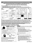
1
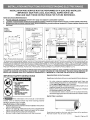
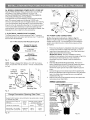
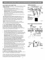
iiiiiiiiiiiiiiiiiiiiiiiiiiiiiiiiiiiiiiiiiiiiiiiiiiiiiiiiiiiiiiiiiiiiiiiiiiiiiiiiiiiiiiiiiiiiiiiiiiiiiiiiiiiiiiiiiiiiiiiiiiiiiiiiiiiiiiiiiiiiiiiiiiiiiiiiiiiiiiiiiiiiiiiiiiiiiiiiiiiiiiiiiiiiiiiiiiiiiiiiiiiiiiiiiiiiiiiii
_¸
Installation
Instrucciones
Instructions
de Instalacion
Es_uff_ Eh_s:t._ic_ _
30"
Electrolux
INSTALLATION AND SERVICE MUST BE PERFORMED
BYA QUALIFIED INSTALLER.
IMPORTANT: SAVE FOR LOCAL ELECTRICAL
INSPECTOR'S
USE.
READ AND SAVE THESE INSTRUCTIONS
FOR FUTURE REFERENCE.
Clearances
1.
2.
3.
and Dimensions
Provide adeauate clearances between the range and adjacent combustible surfaces.
Location--Check location where the ranqe will be installed. Check for proper electrical supply, and the stability of the floor.
Dimensions that are shown must be used. Given dimensions provide minimum clearance. Contact surface must be solid
and level.
RANGE
OVERALL
DIMENSIONS
RANGEELECTRICAL
CONNECTIONS
ii dimensionsfoi
lectricaloutlet locationI
25-3/4"
......... 3o"--.j,,..._
4
re maximum,
/2"
1
|
I
ofrange
/
II
I
Fig,
1
WW
\_,""_"
29-7/8" "'_
-- - -
electrical outlet must
TYPICALCABINETINSTALLATION_
_30"
30"
'k
Minimum
j
I_
_Dashedcubedarea
_Center,ine showswhere the
I
•5/8"**
Door Open
FRONT--
Minimumto
1"4_
wall on either
®'® _
side of range
_F 1
above 36" height.
SIDE
VIEW
--_
1_-13"-_
®'®
Maximumdepth
18" cabinetson
t
eithersideMinimumt°
for cabinets
_
of range.
above
range top.
be installedfor flush to/
-_-111",,,the wall installati°n.
J
-_>
2-5/8"for modelsequipped
withwarmerdrawers,
3-1/2"for modelsequipped
Depthis 28-13/32"withdoor handle.
withstorage drawers
Fig.
2
Fig. 3
<_
30"
O"clearancebelow cookingtop and at rear of range.
*30" MINIMUM CLEARANCE
BETWEEN THE TOP OFTHE COOKING SURFACEAND
THE BOTTOM OFAN UNPROTECTED
WOOD OR METAL
CABINET; OR 24" MINIMUM WHEN BOTTOM OF WOOD OR M ETAL CABINET
IS PROTECTED
BY NOT LESS THAN 1/4" FLAME RETARDANT
M ILLBOARD COVERED WITH NOT LESS THAN NO. 28 MSG SHEET STEEL, 0.015" STAINLESS
STEEL, 0.024" ALUMINUM
OR 0.020" COPPER.
0" CLEARANCE
IS THE MINIMUM
FOR THE REAR OF THE RANGE. FOLLOW ALL DIMENSION
REQUIREMENTS
PROVIDED
ABOVE TO
PREVENT
PROPERTY
DAMAGE,
POTENTIAL
FIRE HAZARD, AND INCORRECT
COU NTERTOP
AND CABINET
CUTS.
TO ELIMINATE THE RISK OF BURNS OR FIRE BY REACHING OVER HEATED SURFACE UNITS, CABINET STORAGE SPACE LOCATED
ABOVE THE SURFACE UNITS SHOULD BE AVOIDED. IF CABINET STORAGE IS TO BE PROVIDED, THE RISK CAN BE REDUCED BY
INSTALLING A RANGE HOOD THAT PROJECTS HORIZONTALLY A MINIMUM OF 5" BEYOND THE BOTTOM OF THE CABINETS.
IMPORTANT
SAFETY
INSTRUCTIONS
Important Note to the Consumer
Keep these instructionswith yourowner's guide forfuture reference.
• ALL RANGES
CAN TIP
• INJURY TO PERSONS
COULD RESULT
• INSTALL ANTI-TIP
DEVICE PACKED WITH
RANGE
• SEE INSTALLATION
INSTRUCTIONS
As when using any appliance generating heat, there are
certain safety precautions you should follow. These are listed
in the Use & Care Guide, read it carefully.
Be sure your range is installed and grounded properly by a
qualified installer or service technician.
Make sure the wall coverings around the range can withstand
the heat generated by the range.
To eliminate the need to reach over the surface elements,
cabi net storage space above the elements should be avoided.
Serial Plate Locations:
_'!_lviV-'1_t#ll_[_ll
If the information in this manual is not followed
exactly, a fire or electrical shock may result causing property
damage, personal injury or death.
Important Notes to the Installer
•
Read all instructions contained in these installation instructions
before installing range.
•
Remove all packing material from the oven compartments
before connecting the gas & electrical supply to the range.
•
Observe all governing codes and ordinances.
•
Be sure to leave these instructions with the consumer.
Serial
plate Iocatio
Serial plate is located on the lower right front frame
Alternate
location may be under cooktop.
of the appliance.
EspaiSol - P&ginas
5-8
BEFORE STARTING
Tools You Will Need
3/16" pilot hole 1-3/4" deep.
in wood or concrete
material.
For leveling legs and Anti-Tip
Bracket:
• Adjustable wrench or channel lock pliers
• 5/16" Nutdriver or Flat Head Screwdriver
• Electric Drill & 1/8" Diameter Drill Bit
head
(Masonry Drill Bit if installing in concrete)
and the leveling
lC.
Materials
You Will
clearance
level
(See
Need:
is ever moved to a different
and installed
with a wrench.
NOTE:
to check
Fig. 7).
between
leg to allow
your
room
Visually
check
secured
by the Anti-Tip
that rear leveling
Bracket
(See
range
A minimum
the bottom
Slide
Fig. 6).
by adjusting
of the range
for the bracket.
adjustments.
range
leg is inserted
by removing
Use a spirit
back
into position
into and fully
lower
panel or
to tilt it forward.
FASTEN
BRACKET
Leveling
Leg --
(w_u_Lo_ FLOO_ MOUNTING)
---_1
BRACKET INSTALLATION
SAFETY WARNING
must also be moved
legs
in place
- Level
of 1/8" is required
attempt
1<--1-1/4
FASTEN
BRACKET
(_Loo_ MOUNTINGONLY)
" Max.
--_1
14-- More
Than
INSTRUCTIONS
I
To reduce the risk of tipping of the range, the range must be
secured to the floor by properly installed Anti-Tip Bracket and
screws packed with the range. Failure to install the anti-tip bracket
will allow the range to tip over if excessive weight is placed on an
open door or if a child climbs upon it. Serious injury might result
from spilled hot liquids or from the range itself.
If range
the bracket
Range
Position
storage drawer.
For models with a Warmer Drawer or broiler
compartment,
grasp the top rear edge of the range and carefully
• Power Supply Cord or
• Copper Electrical Wiring & Metal Conduit
(for hard wiring)
NORMAL INSTALLATION
STEPS
1. ANTI-TIP
- IMPORTANT
to secure
and
the (4) leveling
For electrical supply connection:
• 1/4" & 3/8" Socket driver or Nutdriver
Additional
screwdriver
Level
The screws provided
may be used
Use a 5/16" nut-driver
or flat
location,
the Anti-Tip
Floor Mount
) Bracket
Floor Mount
Fig. 5
--
_
nti-Tip
Bracket
Fig. 6
Bracket
with the range.
Instructions
are provided for installation
in wood or cement
fastened to either the floor or wall. When installed to the wall,
make sure that screws completely
secured in wood or metal. When
sure that screws
do not penetrate
penetrate
dry wall and are
fastening
to the floor or wall,
electrical
wiring
Range Side/v
be
""
Fig. 7
or plumbing.
2. ELECTRICAL
la.
Locate
the
using the Template
Bracket
- (Bracket
may be located
on either the left or right side of the range.
the information
below to locate
the bracket
if template
appliance
technician
Use
is not
NFPA
No. 70 -- latest
available).
Mark the floor or wall where
requirements.
left or right side of the range
This appliance
will be located.
If rear of range
is against the wall or no
further than 1-1/4" from wall
Wiring"
When
when installed, you may use
the wall or floor mount
method.
If molding
is installed
Fig. 4
installing
could create
the back edge of the template
wall and the side edge of template
the side of the range
(See
to the floor.
Fig. 4). Place bracket
For floor
mount,
-- and Local
Electrical
by means
Supply
Cord Kit."
Permanent
Wiring,
Code
of "Permanent
do not leave
excess
wire in
where
located.
of the screw
holes,
under
hazard
if wires become
"Permanent
pinched.
Wire
2a. Models with Factory Connected
Power Supply
Cord. NOTE: Some models may have a factory
on top of
shown
electrical
the rear
installed
in wall. If rear of
installed, attach
the rear of the range
a potential
only as instructed
Connections"
in Step 4c. When using flexible conduit or range
cable use flex connector or range cable strain relief (Fig. 1 1 ).
referencing
locate the bracket
back edge of the template
Mark the location
against
on the mark made
template and mark location of the screw holes
range is further than 1-1/4" from the wall when
bracket
- This
range compartment.
Excess wire in the range compartment
may
not allow the Rear Access Cover to be replaced properly and
and does not allow the bracket to fit flush against the wall, remove
molding or mount bracket to the floor. For wall mount, locate the
by placing
edition
may be connected
or "Power
Connect
bracket
REQUIREMENTS
CONNECTION
must be properly installed and grounded
by a qualified
in accordance
with the National Electrical
Code ANSll
three
(3) conductor
Power Supply
Cord.
Mobile home installations, new branch circuit installations
(1996NEC) or areas where Local Codes do not permit grounding
through neutral require a four (4) conductor power supply cord kit
rated at 125/250 volts minimum and marked for use with ranges.
by placing
will be
in template.
lb, Drill Pilot Holes & Fasten Bracket - Drill a 118"pilot
hole where
to the wall,
screws
are to be located.
If bracket
drill pilot hole at an approximate
(See Fig. 5).
If bracket is to be mounted
to masonry
See Range
is to be mounted
20 ° downward
or ceramic
floors,
angle
drill
a
Connection
Opening
Size Chart
(Figs.
9 & 10) for
cord kit ampere rating information.
Terminals
on end of wires
must be either closed loop or open-end spade lugs with upturned
ends.
2b. MODELS
REQUIRING
POWER
RISK OF FIRE OR ELECTRICAL
SUPPLY
SHOCK
CORD
MAY OCCUR
INCORRECT
SIZE RANGE CORD KIT IS USED, THE
INSTALLATION
INSTRUCTIONS
ARE NOT FOLLOWED
STRAIN
RELIEF
This appliance
BRACKET
minimum,
supply
and marked
10 for cord kit ampere
three
by means of a power
for use with ranges
rating
(3) or four (4) conductors
4a. for 4-Wire
3. ELECTRICAL
supply
cord kit rated at 1251250 volts
information.
(See
shall be used. See Fig.
Fig. 8). Terminals
or 4b. for 3-Wire
CONNECTION
Separate Strain Relief
before installation
Cord must have either
wires must be either closed loop or open-end spade
upturned ends. Cord must have strain relief properly
Steps
OR
IS DISCARDED.
may be connected
cord. Only a power
KIT.
IF AN
on end of
lugs with
installed. See
connections.
Fig. 11
TO RANGE.
The Rear Access Cover must be removed (Fig 9). To remove,
loosen center screw (one screw) and remove cover. The terminal
block will then be accessible.
4A.
POWER
(4-Wire
Before
3 & 4 -Wire
electrical
wall Receptacle
types
&
Connection
wiring
(14-50R)
the manufacturer's
securely
IMPORTANT
installed
terminal
3.
to Fig. 9.
7/8" Dia.
Hole
4.
A_*cess
Cover
5.
source
instructions
block.
DO NOT LOOSEN
which
failure
if these
disconnect
screw
the factory
secure the range wiring to the
or loss of electrical
3 nuts are loosened
the ground
ground
supplied
strap.
or
Remove
& plate to release
installed
ground
discard
screw.
strap from the frame of the appliance.
Cut and
the copper ground strap & plate. KEEP the ground
the copper
Connectthegroundwire(Green)leadwiththeeyelettothe
of the appliance
with the ground
screw
hole in the frame where the ground
installed (See Fig. 12).
screw
Make sure all screws
securely
4-Wire
Pocket
for Cable
Mounting Plate
cover
are tightened
(See
using
and replace
Fig. 9).
Connection
3 Factory installed connections
(DO NOT LOOSEN)
Connect
neutral
center) here
Terminal
Connection
Supply Cord Kit ampere
for kilowatt
rating
Opening
rating information.
Cord Kit
Ampere
Rating
120/240 Volts 120/208 Volts
Fig.
10
See serial plate on range
data,
See Serial Plate on Range for
KW Rating
8.8-16.5 KW
16,6-22.5 KW
Size Chart
7.9-12.5 KW
12.6-18,5 KW
Diameter (inches) of Range
connection Opening
Cord Kit
40/50 Amp
5OAmp
1_3/8 in,
1-3/8 in,
Permanent
Wiring
1-1/8 in,
1-3/8 in.
Connect
line 1
here
Cut ground
strap.
ground strap
& ground plate
Connect
=ine 2
here
Connect
insulated copper
ground wire with
ground screw here
NOTES:
install strain-re=ief
bushing. Center or white
wire must always be
attached to the center
termina= on b=ock
the same
was originally
Fig. 9
Range
the
factory
rear access
1-3/8"
Hole
(See Chart)
to the terminal
NOTE:
may occur
You must
frame
_ar
installation
nut connections
block. Electrical
connection
removed.
(10-5OR)
Range is shipped from factory with 1-3/8" dia. hole as
To use either 7/8" dia. hole or 1-1/8" dia. knockouts
refer
(See Chart)
power
2.
3 Wire Wall
(See Chart)
Mounting
Plate
to Fig.12)
with the strain relief and install (Also see Figs. 9, 10 & 11).
insert the end connectors
for Line 1, Line 2 and Neutral and
exisiting installations
1-1/8" Dia.
Knockout
- Refer
the suggested
Follow
tighten
NOTE:
shown.
review
1.
Allowed for
Receptacle
Instructions
the range
location drawing in Fig. 3. If connecting
to a 4-Wire electrical
system (new branch-circuit
or mobile home requires 4-Wire
4 Wire Wall
Fig. 8
CONNECTIONS
connection):
Required for new and
remodeled installations
Receptacle
CORD
Fig. 12
the
3-Wire
or 4B. POWER CORD CONNECTIONS
(3-Wire Connection Instructions. For existing
- Refer to Fig. 13).
installations ONLY
1.
Follow the manufacturer's
installation
instructions
supplied
strain relief and install (Also see Figs. 9, 10 & 1 1).
2.
insert the end connectors
securely
to the terminal
IMPORTANT
connections
for Line 1, Line 2 and Neutral
block
Make sure all connections
access
cover
Grounding
strap
(See
terminal block (Neutral)
connected
to the range
strap
Codes
do not permit
ground
which
center) here
Terminal
block
and tighten
chassis
4c. 3 & 4-WIRE
may occur
securely
connects
to the range chassis.
by the center, lowest
unless
use of a ground
Ground strap
Connect
line 2
here
if these 3
and replace
the rear
Ground screw
terminal
NOTES:
Install strain-relief
bushing. Center or white
wire must always be
attached to the center
terminal on block
of the
The ground strap is
screw (See Fig. 13). The
National,
State or Local
Fig. 13
for any reason,
to the separate
and to an adequate
PERMANENT
only): A ground
the center
strap.
strap is removed
wire must be connected
to the range
connection
(3-Wire Connections
must not be removed
If the ground
ground
ground
WIRE
a separate
screw
attached
source.
FOR 3 & 4-Wire Permanent Connections
CONNECTIONS.
3 - Wire Permanent Connection - follow Steps 1,2 & 5 below.
4 - Wire Permanent Connection - follow Steps 1 thru 5 below.
Before wiring the range, review the suggested power source location
drawings in Fig. 3. If connecting to a 4-Wire electrical system (new branchcircuit or mobile home requires 4-Wire connection):
1.
(3 & 4 - Wire
installation
2.
Permanent
instructions
Connections)
supplied
Follow
- Tighten all 3
wire leads
Connections).
block (Follow
wire locations
IMPORTANT
NOTE:
connections
which
Tighten
shown
DO NOT
secure
Terminal
block
the manufacturer's
with the strain relief and install.
Line 2
Line 1
(3 & 4 - Wire Permanent
Connections)
Strip insulation away from the
ends of the permanent
wiring for Line 1, Line 2, Neutral (also strip ground
wire on 4-Wire
Ground plate
Ground screw
all 3 wire leads to the terminal
in Fig. 14).
LOOSEN
the range
the factory
wiring
installed
to the terminal
nut
Ground strap
block.
Electrical
failure or loss of electrical connection
may occur if these 3
nuts are loosened
or removed.
NOTE: For 3-Wire Permanent
Connections
3.
Steps
3 & 4 and
Connection
continue
the copper
Disconnect
Fig, 14
5.
the factory installed ground screw & plate to release the factory
copper ground strap from frame of the appliance.
Cut and
strap from the terminal
block.
(4-Wire
Permanent
Connection
(Green)
to the frame
of the appliance
(3 & 4 - Wire
tightened
the ground
KEEP
strap.
the ground
plate and go to Step 4.
ONLY)
Connect
Permanent
securely
Connections)
and replace
the ground
using the ground
shown in Fig. 15. Be sure to install using the same
where the ground screw was originally installed.
5.
Step
Permanent
ground
ONLY)
with
Remove
installed
screw,
4.
skip
(4-Wire
discard
Connect
neutral
(See Fig. 13).
are tightened
on this range
ground
3 Factory installed connections
(DO NOT LOOSEN)
Fig. 9).
Instructions
is installed
NOTE:
with the
NOTE:
DO NOT LOOSEN the factory installed nut
which secure the range wiring to the terminal block.
Electrical
failure or loss of electrical
nuts are loosened
or removed.
3.
Connect
line 1
Connection
screw
wire lead
cover (See
PROPER
& plate as
"
hole in the frame
Make sure all connections
the rear access
PLATE_
GROUND
are
GROUND
SCREW
._A
_NE)
_
r_
4.-WlR E
PERMANENT
GROUND
_OR
CONNECTION
GROUND
WIRE LEAD
Fig. 9).
Fig, 15
NOTE:
Non-terminated
set at approximately
field
wire
compression
connections
must
22 in./Ibs.
5. CAREFULLYSLIDE
RANGE
INTO FINAL LOCATION.
Be sure to provide all the adequate clearances and dimensions
Figs. 1, 2 & 3 before moving appliance into final location.
Carefully
and FULLY
power
slide
range
ENGAGING
cord folds
or storage
drawer.
be
into final
position
THE ANTI-TIP
into the remaining
while
open floor
Be sure to check
inserting
BRACKET
shown in
rear leveling
leg into
(See Fig. 7). Make sure the
area behind
the range
Warmer
the level of the range.
4
Electrolux