1
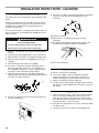
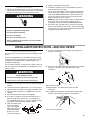
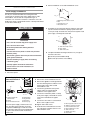
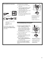
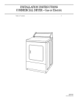
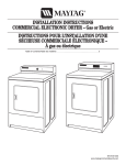
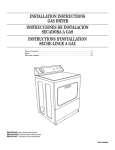
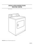
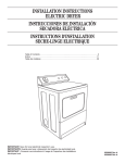
INSTALLATION INSTRUCTIONS
COMMERCIAL STACKED DRYER
Gas (120-Volt, 60-Hz) or Electric (120/240-Volt, 60-Hz)
Table of Contents . . . . . . . . . . . . . . . . . . . . . . . . . . . . . . . . . . . . . . . . . . . . . . . . . . . . . . . . 2
Actual unit may or may not
contain doors with windows
depending on model
W10135152A
www.whirlpool.com
TABLE OF CONTENTS
DRYER SAFETY............................................................................ 2
INSTALLATION REQUIREMENTS .............................................. 4
Location Requirements.............................................................. 4
Tools and Parts .......................................................................... 5
Electrical Requirements ............................................................ 6
Gas Supply Requirements ........................................................ 7
Venting Requirements .............................................................. 8
INSTALLATION INSTRUCTIONS – GAS DRYER .................. 10
Install Coin-Slide and Coin Box ..............................................10
Make Gas Connection..............................................................10
Connect Vent ............................................................................10
Complete Installation ..............................................................10
INSTALLATION INSTRUCTIONS – ELECTRIC DRYER........ 11
Install Coin-Slide and Coin Box ..............................................11
Make Electrical Connection......................................................12
Connect Vent ............................................................................15
Complete Installation ..............................................................15
CHANGING TO A 30- OR 60-MINUTE TIMING CAM ...........16
DRYER SAFETY
■
■
It is recommended that the owner post, in a prominent location, instructions for the customer's use in the event the customer smells
gas. This information should be obtained from your gas supplier.
Post the following warning in a prominent location.
FOR YOUR SAFETY
Do not store or use gasoline or other flammable vapors and liquids in the vicinity of this or any other appliance.
2
WARNING: For your safety, the information in this manual must be followed to minimize
the risk of fire or explosion, or to prevent property damage, personal injury, or death.
– Do not store or use gasoline or other flammable vapors and liquids in the vicinity of this
or any other appliance.
– WHAT TO DO IF YOU SMELL GAS:
• Do not try to light any appliance.
• Do not touch any electrical switch; do not use any phone in your building.
• Clear the room, building, or area of all occupants.
• Immediately call your gas supplier from a neighbor's phone. Follow the gas supplier's
instructions.
• If you cannot reach your gas supplier, call the fire department.
– Installation and service must be performed by a qualified installer, service agency, or
the gas supplier.
In the State of Massachusetts, the following installation instructions apply:
■
Installations and repairs must be performed by a qualified or licensed contractor, plumber, or gasfitter qualified or licensed by
the State of Massachusetts.
■
If using a ball valve, it shall be a T-handle type.
■
A flexible gas connector, when used, must not exceed 3 feet.
IMPORTANT SAFETY INSTRUCTIONS
WARNING: To reduce the risk of fire, electric shock, or injury to persons when using the dryer, follow basic precautions,
including the following:
■
■
■
■
■
■
■
■
Read all instructions before using the dryer.
Do not place items exposed to cooking oils in your dryer.
Items contaminated with cooking oils may contribute to
a chemical reaction that could cause a load to catch fire.
■
Do not repair or replace any part of the dryer or attempt
any servicing unless specifically recommended in this
Use and Care Guide or in published user-repair instructions that you understand and have the skills to carry out.
Do not dry articles that have been previously cleaned in,
washed in, soaked in, or spotted with gasoline, drycleaning solvents, other flammable, or explosive
substances as they give off vapors that could ignite or
explode.
Do not allow children to play on or in the dryer. Close
supervision of children is necessary when the dryer is
used near children.
■
Do not use fabric softeners or products to eliminate static
unless recommended by the manufacturer of the fabric
softener or product.
Do not use heat to dry articles containing foam rubber or
similarly textured rubber-like materials.
Clean lint screen before or after each load.
Keep area around the exhaust opening and adjacent surrounding areas free from the accumulation of lint,dust,
and dirt.
The interior of the dryer and exhaust vent should be
cleaned periodically by qualified service personnel.
Before the dryer is removed from service or discarded,
remove the door to the drying compartment.
Do not reach into the dryer if the drum is moving.
Do not install or store the dryer where it will be exposed
to the weather.
Do not tamper with controls.
■
■
■
■
■
See installation instructions for grounding requirements.
SAVE THESE INSTRUCTIONS
IMPORTANT: The gas installation must conform with local codes, or in the absence of local codes, with the National Fuel Gas
Code, ANSI Z223.1/NFPA 54 or the Canadian Natural Gas and Propane Installation Code, CSA B149.1.
The dryer must be electrically grounded in accordance with local codes, or in the absence of local codes, with the National
Electrical Code, ANSI/NFPA 70 or Canadian Electrical Code, CSA C22.1.
3
INSTALLATION REQUIREMENTS
Tools and Parts
Gather the required tools and parts before starting installation.
Read and follow the instructions provided with any tools listed
here.
Location Requirements
WARNING
Tools needed
■
■
■
■
■
■
■
■
■
■
■
■
■
8" or 10" pipe wrench
8" or 10" adjustable wrench
Flat-blade screwdriver
Phillips screwdriver
Adjustable wrench that opens to 1" (2.5 cm) or hex-head
socket wrench
Level
⁵⁄₁₆" open-end wrench
Utility knife
Vent clamps
Pipe-joint compound resistant to LP gas
Caulk gun and caulk (for installing new exhaust vent)
Pliers
Putty knife
Parts supplied
Remove parts bag from dryer drum. Check that all parts were
included.
■ 3 pin timing cam
■ 6 pin timing cam
■ Sliding extension (2)
■ 10-32 x ⁵⁄₁₆" seriated screw (4)
■ Cotter hair pin
Explosion Hazard
Keep flammable materials and vapors, such as
gasoline, away from dryer.
Do not install in a garage.
Failure to do so can result in death, explosion, or fire.
If installing a gas dryer:
IMPORTANT: Observe all governing codes and ordinances.
■ Check code requirements: Some codes limit or do not permit
installation of clothes dryers in closets or sleeping quarters.
Contact your local building inspector.
■ Make sure that lower edges of the cabinet, plus the back and
bottom sides of the dryer, are free of obstructions to permit
adequate clearance of air openings for combustion air. See
“Recessed Area and Closet Installation Instructions” below for
minimum spacing requirements.
NOTE: The dryer must not be installed in an area where it will be
exposed to water and/or weather.
Recessed Area and Closet Installation Instructions
This dryer may be installed in a recessed area or closet. For
recessed area and closet installations, minimum clearances can
be found on the serial tag on the dryer.
The installation spacing is in inches and is the minimum
allowable. Additional spacing should be considered for ease of
installation, servicing, and compliance with local codes and
ordinances.
If closet door is installed, the minimum unobstructed air opening
in the top and bottom is required. Louvered doors with equivalent
air openings are acceptable.
The dryer must be exhausted outdoors.
No other fuel-burning appliance may be installed in the same
closet as the dryer.
4
Minimum Installation Clearances
Back
Recessed 0 in
(0 cm)
Closet
0 in
(0 cm)
Sides
0 in
(0 cm)
0 in
(0 cm)
Product Dimensions
Top
Front
6 in
—
(15.2 cm)
0 in
7 in
(0 cm)
(17.8 cm)
top
exhaust
0" (0 cm)
6"
(15.2 cm)
0"
(0 cm)
13-1/2"
(34.3 cm)
Back View
41"
(104.1 cm)
bottom
exhaust
closet
door
7"
(17.8 cm)
0" (0 cm)
Closet
side view
0" (0 cm)
27" (68.6 cm)
Recessed
front view
Additional clearances for wall, door and floor moldings may be required or if
external exhaust elbow is used.
Side View
door
76-3/4"
(195 cm)
3" (7.6 cm)
48 sq. in.
(310 sq. cm)*
Front
View
closet
door
24 sq. in.
(155 sq. cm)*
3" (7.6 cm)
23-3/4"
(60.3 cm)
29-1/4"
(74.3 cm)
approx. 1"
(2.5 cm)
*Opening is the minimum for a closet door.
Louvered doors with equivalent air openings are acceptable.
5
Electrical Requirements – Gas Dryer
WARNING
Electrical Shock Hazard
Plug into a grounded 3 prong outlet.
Do not remove ground prong.
Do not use an adapter.
Do not use an extension cord.
Failure to follow these instructions can result in death,
fire, or electrical shock.
IMPORTANT: The dryer must be electrically grounded in
accordance with local codes and ordinances or, in the absence of
local codes, with the National Electrical Code, ANSI/NFPA 70,
latest edition.
If codes permit and a separate ground wire is used, it is
recommended that a qualified electrical installer determine that
the ground path is adequate.
A copy of the above code standards can be obtained from:
National Fire Protection Association
One Batterymarch Park, Quincy, MA 02269
■ A 120 volt, 60 Hz, AC only, 15-amp, fused electrical circuit is
required. A time-delay fuse or circuit breaker is also
recommended. It is recommended that a separate circuit
serving only this dryer be provided.
Recommended Ground Method
Electrical Requirements – Electric Dryer
IMPORTANT: The dryer must be electrically grounded in
accordance with local codes and ordinances or, in the absence
of local codes, with the National Electrical Code, ANSI/NFPA 70,
latest edition.
The National Electric Code requires a 4-wire supply connection
for homes built after 1996, dryer circuits involved in remodeling
after 1996, and all mobile home installations.
If codes permit and a separate ground wire is used, it is
recommended that a qualified electrical installer determine that
the ground path is adequate.
A copy of the above code standards can be obtained from:
National Fire Protection Association
One Batterymarch Park, Quincy, MA 02269
■ A four-wire or three-wire, single-phase, 120/240 volt, 60 Hz,
AC only electrical supply (or four-wire or three-wire,
120/208 volt, if specified on the model/serial rating plate) is
required on a separate, 30-amp circuit, fused on both sides of
the line. A time-delay fuse or circuit breaker is recommended.
Recommended Ground Method
It is your responsibility to contact a qualified electrical installer
to ensure that the electrical installation is adequate and in
conformance with the National Electrical Code, ANSI/NFPA 70,
latest edition, and all local codes and ordinances.
GROUNDING INSTRUCTIONS
■
For a grounded, cord-connected dryer:
This dryer must be grounded. In the event of a malfunction or
breakdown, grounding will reduce the risk of electric shock
by providing a path of least resistance for electric current.
This dryer uses a cord having an equipment-grounding
conductor and a grounding plug. The plug must be plugged
into an appropriate outlet that is properly installed and
grounded in accordance with all local codes and ordinances.
■
The dryer, when installed, must be electrically grounded in
accordance with local codes or, in the absence of local codes,
with the National Electrical Code, ANSI/NFPA 70, latest edition.
GROUNDING INSTRUCTIONS
■
For a grounded, cord-connected dryer:
This dryer must be grounded. In the event of a malfunction or
breakdown, grounding will reduce the risk of electric shock
by providing a path of least resistance for electric current.
This dryer is equipped with a cord having an equipmentgrounding conductor and a grounding plug. The plug must be
plugged into an appropriate outlet that is properly installed
and grounded in accordance with all local codes and
ordinances.
WARNING: Improper connection of the equipmentgrounding conductor can result in a risk of electric shock.
Check with a qualified electrician or service representative or
personnel if you are in doubt as to whether the dryer is
properly grounded. Do not modify the plug provided with the
dryer: if it will not fit the outlet, have a proper outlet installed
by a qualified electrician.
SAVE THESE INSTRUCTIONS
6
For a permanently connected dryer:
This dryer must be connected to a grounded metal,
permanent wiring system, or an equipment-grounding
conductor must be run with the circuit conductors and
connected to the equipment-grounding terminal or lead on
the dryer.
WARNING: Improper connection of the equipmentgrounding conductor can result in a risk of electric shock.
Check with a qualified electrician or service representative or
personnel if you are in doubt as to whether the dryer is
properly grounded. Do not modify the plug on the power
supply cord: if it will not fit the outlet, have a proper outlet
installed by a qualified electrician.
SAVE THESE INSTRUCTIONS
Gas Supply Requirements
WARNING
Explosion Hazard
Use a new CSA International approved gas supply line.
Install a shut-off valve.
Securely tighten all gas connections.
If connected to LP, have a qualified person make sure
gas pressure does not exceed 13" (33 cm) water
column.
Examples of a qualified person include:
licensed heating personnel,
authorized gas company personnel, and
authorized service personnel.
Gas Supply Line
Recommended method
■ Provide a gas supply line of ¹⁄₂" rigid (IPS) pipe to the dryer
location. Pipe joint compounds that resist the action of LP gas
must be used. Do not use TEFLON®† tape. With LP gas,
piping or tubing size can be ¹⁄₂" minimum. Usually, LP gas
suppliers determine the size and materials used in the system.
Alternate method
■ The gas supply may also be connected using ³⁄₈" approved
copper or aluminum tubing. If the total length of the supply
line is more than 20 feet (6.1 m), larger tubing will be required.
If using natural gas, do not use copper tubing. Pipe joint
compounds that resist the action of LP gas must be used.
Flexible metal appliance connector
■ It is recommended that a new flexible stainless steel gas line,
design-certified by CSA International, be used for connecting
the dryer to the gas supply line. (The gas pipe which extends
through the lower rear of the dryer is provided with ³⁄₈" male
pipe thread.)
Failure to do so can result in death, explosion, or fire.
IMPORTANT: Observe all governing codes and ordinances.
This installation must conform with all local codes and
ordinances. In the absence of local codes, installation must
conform with American National Standard, National Fuel Gas
Code ANSI Z223.1/NFPA 54.
A copy of the above code standards can be obtained from:
National Fire Protection Association
One Batterymarch Park, Quincy, MA 02269
The design of this dryer has been certified by CSA International
for use at altitudes up to 10,000 feet (3048 m) above sea level at
the B.T.U. rating indicated on the model/serial plate. Burner input
adjustments are not required when the dryer is operated up to
this elevation.
When installed above 10,000 feet (3048 m), a four percent (4%)
reduction of the burner B.T.U. rating shown on the model/serial
plate is required for each 1,000 foot (305 m) increase in elevation.
For assistance when converting to other gas types and/or
installing above 10,000 feet (3048 m) elevation, contact your local
service company.
Type of Gas
This dryer is equipped for use with natural gas. It is designcertified by CSA International for L.P. (propane and butane) gases
with appropriate conversion. No attempt shall be made to convert
the dryer from the gas specified on the serial/rating plate for use
with a different gas without consulting the serving gas supplier.
Conversion must be done by a qualified service technician. Gas
conversion kit part numbers are listed on the gas valve burner
base.
■ Do not kink or damage the flexible stainless steel gas line
when moving the dryer.
Rigid pipe connection
The rigid pipe connection requires a combination of pipe fittings
to obtain an in-line connection to the dryer.
■ Must include a shutoff valve:
The supply line must be equipped with a manual shutoff valve
installed within 6 ft. (1.8 m) of dryer in accordance with
National Fuel gas Code, ANSI Z223.1. This valve should be
located in the same room as the dryer. It should be in a
location that allows ease of opening and closing. Do not block
access to shutoff valve. The valve is for turning on or shutting
off gas to the dryer.
B
A
C
A. Gas supply line
B. Shutoff valve “open” position
C. To dryer
■ Installed in a confined area:
If the dryer is installed in a confined area such as a bathroom
or closet, provision must be made for enough air for
combustion and ventilation. Check governing codes and
ordinances or refer to the “Recessed Area and Closet
Installation Instructions” in the “Location Requirements”
section.
†®TEFLON is a registered trademark of E.I. Du Pont De Nemours and Company.
7
Gas Supply Pressure Testing
Plan installation to use the fewest number of elbows and turns.
A ¹⁄₈" NPT minimum plugged tapping, accessible for gauge
testing, must be installed immediately upstream of the gas supply
connection to the dryer.
The dryer must be disconnected from the gas supply piping
system during any pressure testing of the system at test
pressures in excess of ¹⁄₂ psig.
A
Exhaust Air Flow
A. Better
B. Good
Venting Requirements
WARNING
B
Allow as much room as possible when using elbows or making
turns. Bend vent gradually to avoid kinking.
Vent outlet is located at the center of the bottom dryer back.
The vent can be routed up, down, left, right, behind the dryer or
straight out the back of the dryer.
Vent System Length
Fire Hazard
Use a heavy metal vent.
Do not use a plastic vent.
Maximum length of vent system depends upon the type of vent
used, number of elbows and type of exhaust hood. The maximum
length for both rigid and flexible vent is shown in the chart.
Maximum Vent Length
Do not use a metal foil vent.
4" (10.2 cm) Diameter Exhaust Hoods
Failure to follow these instructions can result in death
or fire.
Rigid Metal Vent
WARNING: To reduce the risk of fire, this dryer MUST BE
EXHAUSTED OUTDOORS.
■ The dryer vent must not be connected into any gas vent,
chimney, wall, ceiling, or a concealed space of a building.
■ Do not use an exhaust hood with a magnetic latch.
■ Do not install flexible metal vent in enclosed walls, ceilings or
floors.
■ 4" (10.2 cm) heavy metal vent and clamps must be used.
■ Use clamps to seal all joints. Vent must not be connected or
secured with screws or other fastening devices which extend
into the interior of the vent. Do not use duct tape.
IMPORTANT: Observe all governing codes and ordinances.
Use a heavy metal vent. Do not use plastic or metal foil vent.
Rigid metal vent is recommended to prevent crushing and
kinking.
Flexible metal vent must be fully extended and supported when
the dryer is in its final position. Remove excess flexible metal vent
to avoid sagging and kinking that may result in reduced airflow
and poor performance.
An exhaust hood should cap the vent to prevent rodents and
insects from entering the home or business.
Exhaust hood must be at least 12" (30.5 cm) from the ground or
any object that may be in the path of the exhaust (such as
flowers, rocks or bushes).
If using an existing vent system, clean lint from the entire length
of the system and make sure exhaust hood is not plugged with
lint. Replace any plastic or metal foil vent with rigid metal or
flexible metal vent.
8
No. of 90° turns
Box Hood and Louvered Style
Angled Hood Style
0
1
2
3
4
64 ft. (19.5 m)
54 ft. (16.5 m)
44 ft. (13.4 m)
35 ft. (10.7 m)
27 ft. (8.2 m)
58 ft. (17.7 m)
48 ft. (14.6 m)
38 ft. (11.6 m)
29 ft. (8.8 m)
21 ft. (6.4 m)
No. of 90° turns
Box Hood and Louvered Style
Angled Hood Style
0
1
2
3
4
36 ft. (11.0 m)
31 ft. (9.4 m)
27 ft. (8.2 m)
25 ft. (7.6 m)
23 ft. (7.0 m)
28 ft. (8.5 m)
23 ft. (7.0 m)
19 ft. (5.8 m)
17 ft. (5.2 m)
15 ft. (4.6 m)
Flexible Metal Vent
For vent systems not covered by the vent specification chart, see
Whirlpool Service Manual, “Exhausting Whirlpool Dryers,” Part
No. LIT603197, available from your Whirlpool parts distributor.
If dryer is installed in a confined area, such as a bedroom,
bathroom or closet, provision must be made for enough air for
combustion and ventilation. (Check governing codes and
ordinances.) See “Recessed Area and Closet Installation
Instructions” in the “Location Requirements” section.
A 4" (10.2 cm) outlet hood is preferred. However, a 2¹⁄₂" (6.4 cm)
outlet exhaust hood may be used. A 2¹⁄₂" (6.4 cm) outlet creates
greater back pressure than other hood types. For permanent
installation, a stationary vent system is required.
Multiple Dryer Venting
■ A main vent can be used for venting a group of dryers. Main
vent should be sized to remove 200 CFM of air per dryer.
Large-capacity lint screens of proper design may be used in
the main vent if checked and cleaned frequently. The room
where the dryers are located should have make-up air equal
to or greater than the CFM of all the dryers in the room.
■ Back-draft Damper Kits, Part No. 3391910, are available from
your Whirlpool dealer and should be installed in each dryer's
vent to prevent exhausted air from returning into the dryers
and to keep the exhaust in balance within the main vent.
Unobstructed air openings are required.
Each vent should enter the main vent at an angle pointing in the
direction of the airflow. Vents entering from the opposite side
should be staggered to reduce the exhausted air from interfering
with the other vents.
The maximum angle of each vent entering the main vent should
be no more than 30°.
B
A
C
D
A. Exhaust hood or elbow
B. Wall
C. Main collector vent
D. Horizontal vent
E. 180° sweep elbow
F. Vertical vent
G. Roof
E
C
A
30° max.
air flow
If an exhaust hood cannot be used:
The outside end of the main vent should have a sweep elbow
directed downward. If the main vent travels vertically through the
roof, rather than through the wall, install a 180° sweep elbow on
the end of the vent at least 2 feet (61 cm) above the highest part
of the building. The opening wall or roof shall have a diameter ¹⁄₂"
(1.3 cm) larger than the vent diameter. The vent should be
centered in the opening.
B
2 ft. (61 cm) min. above
highest point of building
F
G
Do not install screening or cap over the end of the vent.
A. Individual dryer vent
B. Main vent
Keep air openings free of dry cleaning fluid fumes. Fumes create
acids which, when drawn through the dryer heating units, can
damage dryers and loads being dried.
A clean-out cover should be located on the main vent for periodic
cleaning of the vent system.
9
INSTALLATION INSTRUCTIONS – GAS DRYER
Install Coin-Slide and Coin Box
The collar houses the accumulator timer with actuating arm and
button.
9. Secure the coin slide mechanism from inside the control panel
using the ³⁄₁₆" bolt and washer included with the slide
mechanism.
The factory-installed timer is set to provide 45 minutes (4 pins)
of drying time when activated by the coin slide. Timer cams for
30-minute (6 pins) and 60-minute (3 pins) drying times are
included in the parts bag.
The coin-slide mechanism, control panel lock and key, and coinbox lock and key are not included and are available from usual
industry sources.
10. Install the coin box.
11. Repeat Steps 7, 8, 9 and 10 for the other coin-slide
mechanism.
12. For added security between the upper dryer and the collar,
insert the cotter hair pin through the connecting bolt.
WARNING
Excessive Weight Hazard
Use two or more people to move and install dryer.
Failure to do so can result in back or other injury.
1. Using two or more people, move dryer to desired installation
location.
2. Check that each leg is approximately 1" (2.5 cm) from base.
3. Wipe the interior of the drums thoroughly with a damp cloth.
4. Install coin vaults and locks (not supplied) into meter case
openings.
5. Install control panel lock and key (not supplied).
6. If you wish to change the 45-minute dryer timing cams to
either 30- or 60-minute timing cams, see “Changing to a
30- or 60-Minute Timing Cam,” section. Complete all of the
steps given in that section before going to Step 7.
7. Open control panel and rest it on the bottom edge of the
opening. Attach slide extension (with flange pointing down) to
one of the coin-slide mechanisms.
A
A. slide extension
8. Insert the coin-slide mechanism through the opening to the
left of the control panel.
10
13. Close the control panel.
Make Gas Connection
1. Remove red caps from the gas pipes.
2. Connect gas supply to dryer. Use pipe-joint compound
resistant to the action of L.P. gas for gas connections. If
flexible metal tubing is used, be certain there are no kinks.
3. Open the shutoff valve in the gas supply line.
4. Test all connections by brushing on an approved noncorrosive
leak-detection solution. Bubbles will show a leak. Correct any
leak found.
Connect Vent
1. Using a 4" (10.2 cm) clamp, connect vent to exhaust outlet in
dryer. If connecting to existing vent, make sure the vent is
clean. The dryer vent must fit over the dryer exhaust outlet
and inside the exhaust hood. Make sure the vent is secured to
exhaust hood with a 4" (10.2 cm) clamp.
2. Move dryer into final position. Do not crush or kink vent. Make
sure dryer is level.
3. Check to be sure there are no kinks in the flexible gas line.
Complete Installation
1. With dryer in final position place level on top of the dryer, first
side to side; then front to back. If the dryer is not level, adjust
the legs of the dryer up or down until the dryer is level.
WARNING
Electrical Shock Hazard
Plug into a grounded 3 prong outlet.
2. Plug into a grounded 3 prong outlet.
3. Check dryer operation (some accumulated time may be on
the timer due to factory testing).
Insert coins in slide and press slide in slowly. (Operating time
will accumulate per number of coins and type of timing cam
used.) Push START/RESTART button. Using a full heat cycle
(not the air cycle), let the dryer run for at least five minutes.
Dryer will stop when time is used up.
NOTE: Dryer door must be closed for dryer to operate. When
door is open, dryer stops, but timer continues to run. To
restart dryer, close door and push START/RESTART button.
4. If the burner does not ignite and you can feel no heat inside
the dryer, shut off dryer for five minutes. Check that all supply
valve controls are in “ON” position and that the electrical cord
is plugged in. Repeat five-minute test.
Do not remove ground prong.
Do not use an adapter.
Do not use an extension cord.
Failure to follow these instructions can result in death,
fire, or electrical shock.
INSTALLATION INSTRUCTIONS – ELECTRIC DRYER
Install Coin-Slide and Coin Box
8. Insert the coin-slide mechanism through the opening to the
left of the control panel.
The collar houses the accumulator timer with actuating arm and
button.
The factory-installed timer is set to provide 45 minutes (4 pins)
of drying time when activated by the coin slide. Timer cams for
30-minute (6 pins) and 60-minute (3 pins) drying times are
included in the parts bag.
The coin-slide mechanism, control panel lock and key, and coinbox lock and key are not included and are available from usual
industry sources.
9. Secure the coin slide mechanism from inside the control panel
using the ³⁄₁₆" bolt and washer included with the slide
mechanism.
WARNING
Excessive Weight Hazard
Use two or more people to move and install dryer.
Failure to do so can result in back or other injury.
1. Using two or more people, move dryer to desired installation
location.
2. Check that each leg is approximately 1" (2.5 cm) from base.
3. Wipe the interior of the drums thoroughly with a damp cloth.
4. Install coin vaults and locks (not supplied) into meter case
openings.
5. Install control panel lock and key (not supplied).
6. If you wish to change the 45-minute dryer timing cams to
either 30- or 60-minute timing cams, see “Changing to a
30- or 60-Minute Timing Cam,” section. Complete all of the
steps given in that section before going to Step 7.
7. Open control panel and
A
rest it on the bottom
edge of the opening.
Attach slide extension
(with flange pointing
down) to one of the
coin-slide mechanisms.
A. slide extension
10. Install the coin box.
11. Repeat Steps 7, 8, 9 and 10 for the other coin-slide
mechanism.
12. For added security between the upper dryer and the collar,
insert the cotter hair pin through the connecting bolt.
13. Close the control panel.
11
2. Remove hold-down screw and terminal block cover.
Make Electrical Connection
A
Power Supply Cord Method
D
C
This dryer is manufactured with the neutral ground wire
connected to he neutral (center) of the wiring harness at the
terminal block. If local codes do not permit this type of
connection, use “Four-wire connection”, instructions. Use a ULlisted power supply cord rated 240 volt min., 30-amp and marked
for use with a clothes dryer.
WARNING
B
A. External ground conductor screw
B. Tab
C. Terminal block cover
D. Hold-down screw
3. Assemble 3/4" UL-listed strain relief (UL marking on strain relief)
into the hole below terminal block opening. Tighten strain relief
screws just enough to hold the two clamp sections together. Install
power supply cord through the strain relief.
B
A
Fire Hazard
Use a new UL listed 30 amp power supply cord.
C
Use a UL listed strain relief.
A. Strain relief clamp sections
B. Dryer cabinet
C. Strain relief screws
Disconnect power before making electrical
connections.
Connect neutral wire (white or center wire) to center
terminal (silver).
Ground wire (green or bare wire) must be connected to
green ground connector.
4. Complete installation following instructions for your type of
electrical connection:
■ Four-wire (recommended method)
■ Three-wire (if four-wire is not available)
Connect remaining 2 supply wires to remaining
2 terminals (gold).
Securely tighten all electrical connections.
Failure to do so can result in death, fire, or
electrical shock.
1. Disconnect power.
Power Supply Cord, A
Four-wire electrical
connection:
B
G
A. Spade terminals with
upturned ends
B. Neutral
C. 3/4" UL-listed strain relief
A
C
D
E
F
D. Neutral (white)
E. Ring terminals
F. Ground wire
G. Ground prong
Four-wire power supply cord must have four,
No.-10 copper wires and match a four-wire
receptacle of NEMA Type 14-30R. The fourth
wire (ground conductor) must be identified with
a green cover and the neutral conductor by a
white cover.
12
5. Remove the center terminal block screw.
6. Remove the appliance neutral ground wire
from the external ground conductor screw.
Fasten under center, silver-colored
terminal block screw.
7. Connect the ground wire of the power
supply cord to the external ground
conductor screw. Tighten screw.
8. Connect the neutral wire (white or center)
of the power supply cord under the center
screw of the terminal block. Tighten
screw.
9. Connect the other wires to outer terminal
block screws. Tighten screws.
10. Tighten strain relief screws.
11. Insert tab of the terminal block cover into
slot of the dryer rear panel. Secure cover
with hold-down screw.
B
C
G
F
D
E
A. External ground conductor screw
B. Appliance neutral ground wire
C. Center terminal block screw
D. Outer terminal block screws
E. Strain relief screw
F. Neutral (center wire)
G. Ground wire
Power Supply Cord,
Three-wire electrical connection:
5. Loosen or remove the center terminal
block screw.
6. Connect the neutral wire (white or center)
of the power supply cord to the center,
silver-colored terminal screw of the
terminal block. Tighten screw.
7. Connect the other wires to outer terminal
block screws. Tighten screws.
8. Tighten strain relief screws.
9. Insert tab of the terminal block cover into
slot of the dryer rear panel. Secure cover
with hold-down screw.
A
This blade connected to
this conductor.
E
D
Use this method where local codes permit connecting
neutral ground wire to neutral wire:
A
B
B
F
E
C
D
A. External ground conductor screw
B. Center terminal block screw
C. Outer terminal block screws
D. Strain relief screw
E. Neutral (center wire)
F. Appliance neutral ground wire
C
A. Spade terminals with upturned ends
B. Ring terminals
C. Neutral (white or center)
D. ³⁄₄" UL-listed strain relief
E. Neutral
Three-wire power supply cord must
have three, No.-10 copper wires and
match a three-wire receptacle of NEMA
Type 10-30R.
Use this method where local codes do not permit
connecting neutral ground wire to neutral wire:
A
5. Remove the center terminal block screw.
C
6. Remove the appliance neutral ground wire
B
from the external ground conductor
D
screw. Connect the appliance neutral
ground wire and the neutral wire (white or
center) of the power supply cord under
the center, silver-colored terminal block
screw. Tighten screw.
7. Connect the other wires to outer terminal G
block screws. Tighten screws.
8. Tighten strain relief screws.
E
9. Insert tab of the terminal block cover into
slot of the dryer rear panel. Secure cover
F
with hold-down screw.
10. After reattaching the terminal cover,
connect a separate copper ground wire
A. Separate copper ground wire
from the external ground conductor screw
B. External ground conductor screw
C. Appliance neutral ground wire
to an adequate ground.
D. Center terminal block screw
If codes permit and a separate ground wire is
E. Outer terminal block screws
used, it is recommended that a qualified
F. Strain relief screw
electrician determine that the ground path is
G. Neutral (center wire)
adequate.
13
1. Disconnect power.
2. Remove hold-down screw and terminal block cover.
Direct Wire Method
A
WARNING
D
C
B
A. External ground conductor screw
B. Tab
C. Terminal block cover
D. Hold-down screw
Fire Hazard
Use 10 gauge solid copper wire.
Use a UL listed strain relief.
Disconnect power before making electrical
connections.
Connect neutral wire (white or center wire) to center
terminal (silver).
Ground wire (green or bare wire) must be connected to
green ground connector.
3. Install ³⁄₄" conduit connector into the hole below the terminal
block opening. Connect flexible metallic conduit and tighten
connector screw. Install direct wire cable through the flexible
metallic conduit.
B
A
Connect remaining 2 supply wires to remaining
2 terminals (gold).
Securely tighten all electrical connections.
A. Conduit connector
B. Dryer cabinet
C. Connector screw
Failure to do so can result in death, fire, or
electrical shock.
Power supply cable must match power supply (4-wire or 3-wire)
and be:
■ Flexible armored cable or nonmetallic sheathed copper cable
(with ground wire), protected with flexible metallic conduit. All
current-carrying wires must be insulated.
■ 10-gauge solid copper wire (do not use aluminum).
■ At least 5 ft. (1.52 m) long.
Direct Wire,
Four-wire electrical connection:
A
1" (2.5 cm)
of wires
stripped of
insulation
to
disconnect
box
B
C
D
5" (12.7 cm)
Shape ends
of wires into
a hook.
Strip 5" (12.7 cm) of outer covering
from end of cable. Leave green or bare
ground wire at 5" (12.7 cm). Cut 1¹⁄₂"
(3.8 cm) from 3 remaining wires. Strip
insulation back 1" (2.5 cm).
A. ³⁄₄" conduit connector
B. Neutral (white or center)
C. Ground wire (green or bare)
D. 10-gauge, 3 wire with ground wire in
14
C
4. Complete installation following instructions for your type of
electrical connection:
• Four-wire (recommended method)
• Three-wire (if four-wire is not available)
B
5. Remove the center terminal block screw.
6. Remove the appliance neutral ground
wire from the external ground conductor
screw. Fasten under center, silvercolored terminal block screw.
7. Connect the ground wire (green or bare)
of the direct wire cable to the external
ground conductor screw. Tighten screw.
8. Place the hooked end of the neutral wire
(white or center) of the direct wire cable
under the center screw of the terminal
block (hook facing right). Squeeze hook
end together. Tighten screw.
9. Place the hooked ends of the other
direct wire cable wires under the outer
terminal block screws (hook facing right).
Squeeze hooked ends together. Tighten
screws.
10. Insert tab of the terminal block cover into
slot of the dryer rear panel. Secure cover
with hold-down screw.
A
C
F
E
D
A. External ground conductor screw
B. Appliance neutral ground wire
C. Center terminal block screw
D. Outer terminal block screws
E. Neutral (center wire)
F. Green or bare ground wire
Direct Wire,
Three-wire electrical connection:
Three wire with ground wire: green or bare
wire cut short. Wire is not used. Dryer is
grounded through neutral conductor.
A
to
disconnect
box
1" (2.5 cm)
of wires
stripped of
insulation
B
C
3-1/2" (8.9 cm)
Shape ends
of wires into
a hook.
Strip 3¹⁄₂" (8.9 cm) of outer
covering from end of cable. Strip
insulation back 1" (2.5 cm). If using
3 wire cable with ground wire, cut
green or bare wire even with outer
covering.
A. ³⁄₄" conduit connector
B. Neutral (white or center)
C. 10-gauge, 3 wire with ground wire in
flexible metallic conduit
Use this method where local codes permit
connecting neutral ground wire to
neutral wire:
5. Loosen or remove the center terminal
block screw.
6. Place the hooked end of the neutral wire
(white or center) of the direct wire cable
under the center screw of the terminal
block (hook facing right). Squeeze
hooked end together. Tighten screw.
7. Place the hooked ends of the other
direct wire cable wires under the outer
terminal block screws (hook facing right).
Squeeze hooked ends together. Tighten
screws.
8. Insert tab of the terminal block cover into
slot of the dryer rear panel. Secure cover
with hold-down screw.
A
B
E
D
C
A. External ground conductor screw
B. Center terminal block screw
C. Outer terminal block screws
D. Neutral (center wire)
E. Appliance neutral ground wire
Use this method where local codes do
not permit connecting neutral ground
wire to neutral wire:
5. Remove the center terminal block screw.
6. Remove the appliance neutral ground wire
from the external ground conductor screw.
Connect the appliance neutral ground wire
and the neutral wire (white or center) of the
direct wire cable under the center, silvercolored terminal block screw. Tighten
screw.
7. Connect the other wires to outer terminal
block screws. Tighten screws.
8. Insert tab of the terminal block cover into
slot of the dryer rear panel. Secure cover
with hold-down screw.
9. After reattaching the terminal cover,
connect a separate copper ground wire
from the external ground connector screw
to an adequate ground.
If codes permit and a separate ground wire is
used, it is recommended that a qualified
electrician determine that the ground path is
adequate.
Connect Vent
1. Using a 4" (10.2 cm) clamp, connect vent to exhaust outlet in
dryer. If connecting to existing vent, make sure the vent is
clean. The dryer vent must fit over the dryer exhaust outlet
and inside the exhaust hood. Make sure the vent is secured to
exhaust hood with a 4" (10.2 cm) clamp.
2. Move dryer into final position. Do not crush or kink vent. Make
sure dryer is level.
Complete Installation
1. With dryer in final position place level on top of the dryer, first
side to side; then front to back. If the dryer is not level, adjust
the legs of the dryer up or down until the dryer is level.
A
C
B
D
F
E
A. Separate copper ground wire
B. External ground conductor screw
C. Appliance neutral ground wire
D. Center terminal block screw
E. Outer terminal block screws
F. Neutral (center wire)
2. Plug in dryer or reconnect power.
3. Check dryer operation (some accumulated time may be on
the timer due to factory testing).
Insert coins in slide and press slide in slowly. (Operating time
will accumulate per number of coins and type of timing cam
used.) Push START/RESTART button. Using a full heat cycle
(not the air cycle), let the dryer run for at least five minutes.
Dryer will stop when time is used up.
NOTE: Dryer door must be closed for dryer to operate. When
door is open, dryer stops, but timer continues to run. To
restart dryer, close door and push START/RESTART button.
4. If drying time is too long, make sure lint screen is clean.
5. Now start the dryer and allow it to complete a full heat cycle
(not air cycle) to make sure it is working properly.
15
CHANGING TO A 30- OR 60-MINUTE TIMING CAM
5. Insert a narrow, flat-blade screwdriver under the timing cam
near the clock shaft. Gently lift cam straight up and off shaft
making sure that the V-shaped notch clears the ratchet tooth.
WARNING
A
B
C
Electrical Shock Hazard
D
Disconnect power before making cam changes.
Failure to follow these instructions can result in death
or electrical shock.
You can install the 30-minute or 60-minute timing cam (shipped
with dryer) as follows:
1. Unplug dryer or disconnect power.
2. Unlock control panel. Lift up and rotate out from cabinet.
Control panel will still be attached to cabinet.
3. Use a Phillips screwdriver to loosen (but not remove) timer
mounting bracket screw. Lift up to remove timer assembly
and bracket from cabinet.
4. Turn the timing cam by hand until the V-shaped notch lines up
below the ratchet tooth.
A
B
A. Ratchet tooth
B. Timing cam
C. Drive lug
D. V-shaped notch
6. Place new cam (hub side down) over clock shaft. Line up flat
side of shaft with flat side of cam hole. Check that drive lug is
in place.
7. Turn cam until V-shaped notch lines up with ratchet tooth.
8. Press cam down in place on clock shaft. Make sure that
V-shaped notch clears the ratchet tooth.
9. Reattach the timer bracket assembly; then tighten the screws.
10. Repeat steps for the other timer.
11. Close and lock the control panel.
12. Plug in dryer or reconnect power.
C
A. Ratchet tooth
B. Timing cam
C. V-shaped notch
Maintenance instructions:
■ Clean lint screen after each cycle.
■ Removing accumulated lint:
■ From inside the dryer cabinet:
Lint should be removed every 2 years or more often,
depending on dryer usage. Cleaning should be done by a
qualified person.
■ From the exhaust vent:
Lint should be removed every 2 years, or more often,
depending on dryer usage.
W10135152A
© 2007.
All rights reserved.
If dryer does not operate check the following:
■ Electric supply is connected.
■ Circuit breakers are not tripped or fuses are not blown.
■ Door is closed.
■ Controls are set in a running or “ON” position.
■ START button has been pushed firmly.
■ For gas dryers, check that gas supply shutoff valves are set in
open position.
If you need assistance:
The Commercial Laundry Support Center will answer any
questions about operating or maintaining your dryer not covered
in the Installation Instructions. The Commercial Laundry Support
Center is open 24 hours a day, 7 days a week. Just dial
1-800 NO BELTS (1-800-662-3587) — the call is toll free.
When you call, you will need the dryer model number and serial
number. Both numbers can be found on the serial-rating plate
located in the dryer door well.
11/2007
Printed in U.S.A.