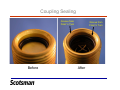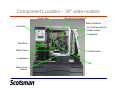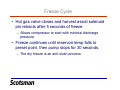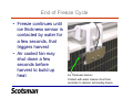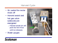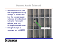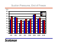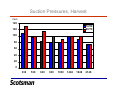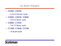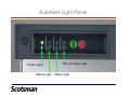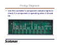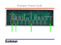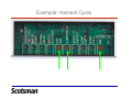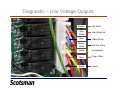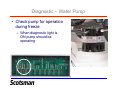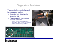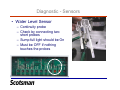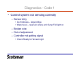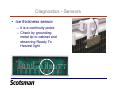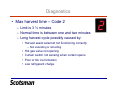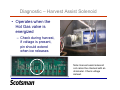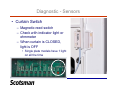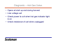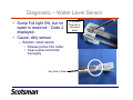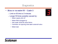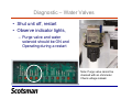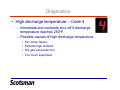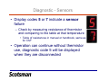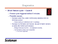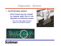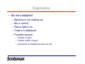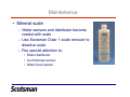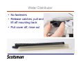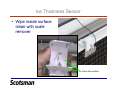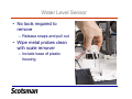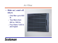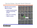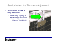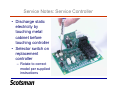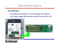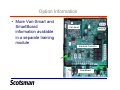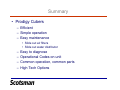
1
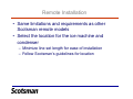
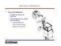
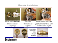
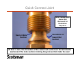
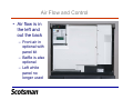
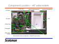
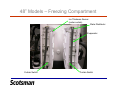
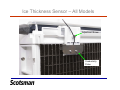
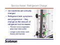
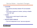
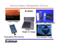
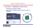
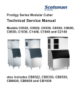
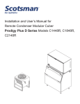
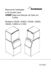
Prodigy Cuber Technical
Training
Revised 2009
Introduction
•
•
•
•
•
Overview
Installation
Operation
Diagnosis
Service
Prodigy Overview
• Modular cubers
– Air cooled, water cooled, remote air cooled
• Remote low side in separate presentation
• 22”, 30” and 48” wide platforms
– 22 and 30 inch platforms have one evaporator
– 48 inch platforms have two evaporators
• Common look and operation across models
• Front service access to most components
Model Number Scheme
• C0330SA-1A
–
–
–
–
–
–
–
C = cuber
03 = 300 lb category
30 = cabinet width in inches
S = small or half dice cube
A = air cooled
-1 = voltage code
A = series
Ice Form
• Either half or full
dice cubes
– Small – half dice
– Medium – full dice
C0322 and C0522
• 22” wide models
– 23” tall
• Evaporator on right
– C0322 has 6” high evaporator
• Air and water cooled models
– C0522 has 12” high evaporator
• Air, water, and remote models
C0330, C0530, C0630, C0830 and C1030
• 30” wide models
• Evaporator on right
– C0330 has 6” high evaporator
• 23” tall cabinet
– C0530, C0630 have 12” high
evaporators
• 23” tall cabinet
– C0830 and C1030 have 18” high
evaporators
• 29” tall cabinet
C1448, C1848, C2148
• 48” wide models
• Two 18” high evaporators
face each other
• Similar operation to smaller
models
– Same control system &
options
– Same curtains
– Same sensors
– Same water distributors
Prodigy Installation – All Models
•
•
•
•
•
•
Set the machine in place
Remove any packing
Level the cabinet
Connect drain (s)
Connect water supply
Remotes: Route and connect tubing to
condenser
• Add any optional accessories
– Smart Board, Vari Smart, Air Baffle, Front Air In
• Connect power
Prodigy Installation – Air Cooled
• Potable water connects to 3/8
fitting on back of cabinet
– Fitting is 3/8” female pipe thread –
direct connection to inlet water
solenoid valve
• Adapter to 3/8” male flare packed in unit
• Reservoir drain fitting is ¾” female
pipe thread
– Vent for proper draining
– Minimum slope of ¼” fall per foot of
horizontal run
Prodigy Installation – Water Cooled
• Same as air cooled plus
an inlet and drain for the
water cooled condenser
Connect Water
Supply to Water
Regulating
Valve Inlet
– Water cooled inlet should
not be filtered
– Water cooled drain tube
should not be vented
Condenser
Drain
Prodigy Installation – Remote Air Cooled
• MUST use condensers
with headmaster in them:
– ERC111, 211, 311 and 611
– RTE line sets – 10, 20, 40, or
75 foot lengths
• 3/8 liquid
• 1/2 discharge
– Power supplied by ice
machine for fan motor
– Same limitations as other
current models
Remote System Configuration
Remote Condenser
Hot Gas
Valve
Head
Pressure
Control
Valve
C1448R,
C1848R,
C2148R
Refrigeration
Circuit
TXV
Discharge Line
Suction
Receiver
Hot Gas
Valve
TXV
Heat
Exchange
Suction
Accumulator
Compressor
Remote Installation
• Same limitations and requirements as other
Scotsman remote models
• Select the location for the ice machine and
condenser
– Minimize line set length for ease of installation
– Follow Scotsman’s guidelines for location
Remote Installation
• Typical Installation
– Condenser above ice
machine
– Precharged line set coiled
within building
• Use horizontal coil
• NEVER leave excess
coiled up on the roof!
Remote Installation
Clean and Lubricate
Quick Connect
Couplings
Use Two
Wrenches to
Tighten
Rotate Swivel Nut One
Quarter Turn More After
Nut Becomes Tight
Incomplete
Assembly:
One
Thread
Showing
Quick Connect Joint
Note: Shown With
Swivel Nut
Removed for
Illustration
Purposes
Seat on Male
Section
Shoulders on
Swivel Nut
Section
At final ¼ turn, the shoulders of the swivel nut section are forced into the
seat area of the male section, forming the grooves that make the seal
Coupling Sealing
Groove from
Final ¼ Turn
Before
Groove from
Final ¼ Turn
After
Components
• Refrigeration:
– Compressor, condenser, thermostatic expansion
valve, hot gas valve, evaporator, and R-404A
• One hot gas valve and one TXV per evaporator
– Remotes also have a liquid line valve
• Water:
– Water pump, inlet water solenoid valve, purge valve,
water distributor
Components
• Electrical
– PTCR for compressor starting
– Harvest assist solenoid
– Fan motor – air cooled and
remote air cooled
– Fan cycling pressure switch
for self contained air cooled
• Control System
– 12 volt transformer
– Electronic controller
• Operates all loads
• Sensors
–
–
–
–
–
–
Water level sensor
Ice thickness sensor
Curtain switch
Fan pressure switch;
Water temperature sensor
Discharge temperature
sensor
– High pressure cut out on
some models
Component Location – 30” wide models
Purge Valve
Harvest Assist Solenoid
Water Distributor
Controller
Ice Thickness Sensor
(under curtain)
Evaporator
Fan Motor
Water Pump
Curtain Switch
Compressor
TXV
Water Level
Sensor
Air Flow and Control
• Air flow is in
the left and
out the back
– Front air in
optional with
panel kit
– Baffle is also
optional
– Left white
panel no
longer used
Component Location – 48” wide models
Purge Valve
Controller
Harvest Assist Solenoid
Freezing Compartment
Fan Motor
TXV
Water Pump
Compressor
Water Level
Sensor
Second water sensor on right side – limits fill if unit not level.
TXV
48” Models – Freezing Compartment
Ice Thickness Sensor
(under curtain)
Water Distributor
Evaporator
Curtain Switch
Curtain Switch
Ice Thickness Sensor – All Models
Adjustment Screw
Conductivity
Probe
Prodigy Operation
• Electrical Sequence
– Power up, controller does self check
– Power Light glows Green
– Push and release the green ON button to start the
unit
ON
OFF
Start Up – Air and Water Cooled
• Reservoir emptied and refilled
–
–
–
–
Purge valve opens, water pump starts
Hot gas and harvest assist solenoid activate
Inlet water valve opens, water fills the reservoir
Purge valve closes, pump shuts off
• When the reservoir is full, the water stops and
the compressor and pump start
– Fan motor will start when discharge pressure
increases to cut in point of fan cycle switch
Start Up - Remote
• 4 hour compressor soak out before operation
• Open receiver outlet valve
• Push and release ON switch
–
–
–
–
–
Purge valve opens, water pump starts
Hot gas and harvest assist solenoid activate
Inlet water valve opens, water fills the reservoir
Purge valve closes, pump shuts off
When the reservoir is full, the water stops, the liquid
line valve opens and the compressor and pump start
Water Control – All Models
• Water Level Sensor
– Conductivity Probe
– Water fills when midlength probe is not
touching water
– Water stops filling
when short probe
touches water
• Snaps out of reservoir
cover for ease of
maintenance
Freeze Cycle
• Hot gas valve closes and harvest assist solenoid
pin retracts after 5 seconds of freeze.
– Allows compressor to start with minimal discharge
pressure
• Freeze continues until reservoir temp falls to
preset point, then pump stops for 30 seconds.
– The dry freeze is an anti-slush process
End of Freeze Cycle
• Freeze continues until
ice thickness sensor is
contacted by water for
a few seconds, that
triggers harvest
• Air cooled fan may
shut down a few
seconds before
harvest to build up
heat
Ice Thickness Sensor
Contact with water makes circuit from
controller to cabinet, terminating freeze
Harvest Cycle
• Air cooled fan motor
shuts off
• Harvest assist and
hot gas valve
solenoids are
energized
– Harvest assist pin will
push but not move
until ice releases
• Water purges
Harvest Assist Solenoid
• Harvest continues until
the evaporator heats up
enough to release the
ice, the harvest assist
solenoid pin will extend
fully and the ice will
release as a unit,
forcing the curtain open
• Design change to
separate pin mid 2009
Harvest Assist Pin
Curtain Switch
• The curtain switch
opening terminates
harvest.
– Stays open = shuts off.
If it closes again, a new
freeze cycle begins.
– Switch is the magnetic
reed type
– Supplier and wire
routing change in mid
2008
Ice Bridge
1/8” Bridge
Too Big
Just Right,
Just Right,
most models Medium cube,
C0322 and
C0330
Too Small
Total Cycle Times
Minutes
18
70/50
90/70
16
14
12
10
8
6
4
2
0
330
530
630
830
1030
1448
1848
2148
Harvest Cycle Times (seconds)
Seconds
90
70/50
90/70
80
70
60
50
40
30
20
10
0
330
530
630
830
1030
1448
1848
2148
Suction Pressures, End of Freeze
PSIG
45
70/50
90/70
40
35
30
25
20
15
10
5
0
330
530
630
830
1030
1448
1848
2148
Suction Pressures, Harvest
PSIG
140
70/50
90/70
120
100
80
60
40
20
0
330
530
630
830
1030
1448
1848
2148
Ice Batch Weights
• C0322, C0330
– 2.4 to 2.6 lb per cycle
• C0522, C0530, C0630
– 4.5 to 5 lb per cycle
• C0830, C1030
– 7 to 7.3 lb per cycle
• C1448, C1848, C2148
– 14 lb per cycle
AutoAlert Light Panel
Power Light
Status Light
Time to Clean Light
Water Light
AutoAlert Light Panel
Optional
Vari-Smart
Control
Location
On Switch Button
Off Switch Button
Prodigy Controller
AutoAlert
Lights
On and Off
Switches
Manual Harvest
and Clean
Switches
Code Display
Component
Indicator
Lights
Place for Optional Accessory
Code Display
• Letter codes
show
operational
status
• Number codes
show shut
down causes
5 Controller Shut Down Causes
• Exceeds limit on water fill time
– 5 minutes
• Exceeds limit on maximum freeze time
– 45 minutes
• Exceeds limit on maximum harvest time
– 3.5 minutes
• End of freeze triggered too soon
– Before 6 minutes into the freeze cycle
• Discharge temperature too high
– Exceeds 250 degrees F.
Controller Reaction
• Exceeds water fill time
– Shuts down, attempts refill every 20 minutes
• Exceeds maximum freeze time
– Completes harvest, tries another cycle
• Exceeds maximum harvest time
– Shuts down, restarts after 50 minutes
• End of freeze triggered too soon
– Completes timed harvest, tries another cycle.
• Discharge temperature exceeds 250 degrees F.
– Immediate shut down
Controller Auto Restart
• From diagnostic causes
– Retries 2 times, if fails again 3rd time, machine must
be manually reset
• From water interruption
– Will continuously restart every 20 minutes
• From power failure
– Goes thru a timed harvest (3 minutes)
Controller Button Processes
• Reset
– Push and release Off,
push and release On
Control Button Processes
• Recall diagnostic code
– Push and hold Off to
shut the machine down
– Push and hold Off
again until the display
code changes
– Push and release the
Harvest button to cycle
thru the last 10
diagnostic codes, from
latest to oldest
Controller Button Processes
• Clear all diagnostic codes
– Push and hold Off to shut the machine down
– Push and hold both the Clean and Harvest buttons for
3 seconds
Controller Button Processes
• View/Change water
purge
– Push and hold Off to shut
the machine down
– Push and hold Off again
until the display code
changes – code displayed
is the current purge setting
– Press and release the On
button to cycle to another
setting – 1 to 5 or A for
Automatic
WaterSense Automatic Purge
• Controller measures conductivity of the reservoir
water
• Adjusts purge water amount based on the
water’s dissolved solids
– Display shows an A if set to Automatic (factory
default)
• Purge can also be manually set
– 1 is minimum
– 5 is maximum
Other Controller Button Processes
• Empty reservoir
– Push and hold Off to shut the machine
down
– Push and hold Clean button until the
display shows a dash, pump will drain
the reservoir for 30 seconds, repeat as
needed
Other Controller Button Processes
• Adjust time interval for de-scale light
– Default is 6 months power up time
– To adjust times:
•
•
•
•
Push and hold Off to shut the machine down
Press and hold harvest button for 3 seconds.
Display shows current time to clean months
Pressing clean button repeatedly will cycle through one of 4
possible settings: 6, 5, 4 or 3 months
• Rev 5 and higher controllers (11/08 and later) settings are 4
or 6 months, 1 year or disabled (4,6,1 or 0 in code display)
• Test mode will be covered in the Diagnostic
Section
Prodigy Diagnosis
• Use the controller’s component indicator lights to
check if a component is operating when it should
be.
Example: Freeze Cycle
Example: Harvest Cycle
Diagnostic – Line Voltage Outputs
Brown
Fan Motor
Red
White
Inlet Water Sol
Blue
Water Pump
Brown
White
Hot Gas Valve
Yellow
Compressor
Red
Purge Valve
Black
Line In
Diagnostic Process
• Check diagnostic code
– Use codes as a guide to the root cause
– Codes listed on the controller overlay
• Remember the Recipe for Ice – a malfunction
will be in one of these areas:
– Water
– Refrigeration
– Electrical
Diagnostics
• Max freeze time diagnostic – Code 1
– Limit is 45 minutes
– Typical cycle is much shorter
• 15 to 20 minutes
– Long freeze cycle causes:
• Lack of water
• Lack of refrigeration effect
• Not sensing ice formation
Diagnostics – Code 1
• Lack of water flow potential causes:
– Water pump failure
– Leaking pump hose
– False Sump Full signal from Water Level Sensor
• Lack of refrigeration may be caused by:
–
–
–
–
–
–
–
Dirty air filters
Fan motor or fan pressure control failure
Water supply to water cooled condenser failure
Low charge
TXV superheat not correct
Compressor contactor failure
Compressor overheated or off
Diagnostic – Water Pump
• Check pump for operation
during freeze
– When diagnostic light is
ON pump should be
operating
Diagnostic – Fan Motor
• Two controls – controller and
fan pressure switch
– Controller light ON when fan
should be ON
– Pressure switch then controls
power to fan motor
• Jump pressure switch wires
together, then power up unit and
check fan motor operation
Diagnostic - Sensors
• Water Level Sensor
– Continuity probe
– Check by connecting two
short probes
– Sump full light should be On
– Must be OFF if nothing
touches the probes
Diagnostics - Code 1
• Control system not sensing correctly
– Sensor dirty
• Ice thickness – large bridge
• Water level – reservoir empty and Sump Full light on
– Broken wire
– Out of adjustment
– Controller not getting signal
• Check Ready to Harvest Light
Diagnostics - Sensors
• Ice thickness sensor
– It is a continuity probe
– Check by grounding
metal tip to cabinet and
observing Ready To
Harvest light
Diagnostics
• Max harvest time – Code 2
– Limit is 3 ½ minutes
– Normal time is between one and two minutes
– Long harvest cycle possibly caused by:
• Harvest assist solenoid not functioning correctly
– Not extending or retracting
•
•
•
•
Hot gas valve not opening
Curtain switch not sensing when curtain opens
Poor or No ice formation
Low refrigerant charge
Diagnostic – Harvest Assist Solenoid
• Operates when the
Hot Gas valve is
energized
– Check during harvest,
if voltage is present,
pin should extend
when ice releases
Note: Harvest assist solenoid
coil cannot be checked with an
ohmmeter. Check voltage
instead.
Diagnostic – Harvest Assist Solenoid
• Spring retracts pin
when power is off
– If pin does not retract,
check for binding in
evaporator bushing
Harvest Assist Solenoid Pin
Diagnostic - Sensors
• Curtain Switch
– Magnetic reed switch
– Check with indicator light or
ohmmeter
– When curtain is CLOSED,
light is OFF
• Single plate models have 1 light
on all the time
Diagnostic – Hot Gas Valve
• Opens at start up and during harvest
• Line voltage coil
• Check power to coil when hot gas indicator light
is on
• Check resistance of coil when unplugged
Diagnostic – Water Level Sensor
• Sump Full light ON, but no
water in reservoir - Code 2
displayed.
• Cause: dirty sensor
– Solution: clean sensor
• Release probes from holder
• Clean probes and holder
thoroughly
Key Area to Clean
To Release:
Push pin in,
pull probe
down
Diagnostics
• Slow or no water fill – Code 3
– Limit on fill time is 5 minutes
– Longer fill times possibly caused by:
•
•
•
•
•
Water supply shut off
Water filters plugged up
Inlet water solenoid valve failure
Controller not opening inlet water solenoid valve
Water leak
Diagnostic – Water Valves
• Shut unit off, restart
• Observe indicator lights,
– Purge valve and water
solenoid should be ON and
Operating during a restart
Note: Purge valve cannot be
checked with an ohmmeter.
Check voltage instead.
Inlet Water Solenoid Valve
• Quick test: In Freeze, pull Water Level Sensor out
of reservoir – Sump Empty light will switch ON
and Inlet Water Solenoid Valve should open to fill
the reservoir.
– Note: If Sump Full light is ON water valve will not open
Diagnostics
• High discharge temperature – Code 4
– Immediate and complete shut off if discharge
temperature reaches 250oF.
– Possible causes of high discharge temperature
•
•
•
•
Fan motor failure
Extreme high ambient
Hot gas valve leak thru
Too much superheat
Diagnostic - Sensors
• Display codes 5 or 7 indicate a sensor
failure
– Check by measuring resistance of thermistor
and comparing to the table at that temperature
• Table of resistances in manual or handbook, same as
for CM3
• Operation can continue without thermistor
use, diagnostic code 5 will be displayed
when they are disconnected
Diagnostics
• Short freeze cycle – Code 8
– Freeze cycle triggered before 6 minutes
– Possible causes
• Improper water flow, water continuously splashes onto ice
thickness sensor
– Scale build up in distributor and / or spillway
• Improper ice formation and harvest, top part of batch remains
on plate after bottom part releases
– Bridge thickness too thin – not adjusted correctly
– Ice formation varies over evaporator
» Too much superheat
Diagnostics - Sensors
• Ice thickness sensor
– Short freeze may be caused
by irregular water flow or misadjusted ice thickness sensor
• Too thin may trigger harvest
before 6 minutes of freeze
Diagnostics
• No ice complaint
–
–
–
–
–
Machine is not making ice
Bin is not full
Status light is on
Code b is displayed
Possible causes:
• Curtain is open
• Curtain switch is open
• Vari-smart is installed and set too low
Diagnostics – Curtain Switch
• Light is ON when switch is Open
– Unused switch light is always on
• Move the curtain
– Check if the light cycles with the
curtain’s movement or
– Use ohmmeter on switch leads
Diagnostic – Test Mode
• Depress and HOLD Off for 3 seconds, release
then
• Depress and HOLD Clean for 3 seconds
– The controller will go through a programmed
sequence of switching the components on and off.
• The Diagnostic lights will switch on and so will the load
– Fan motor is an exception, the fan pressure control will keep
the fan motor off
• If the light is ON and the load is not, further check of the
motor or solenoid coil is required.
• If the lights all match component operation, there is nothing
wrong with either the controller or the components.
Maintenance
• Mineral scale
– Water sensors and distributor become
coated with scale
– Use Scotsman Clear 1 scale remover to
dissolve scale
– Pay special attention to:
• Water distributor
• Ice thickness sensor
• Water level sensor
Water Distributor
• No fasteners
• Release catches, pull and
lift off mounting track
• Pull cover off, rinse out
Ice Thickness Sensor
• Wipe inside surface
clean with scale
remover
Clean this surface
Water Level Sensor
• No tools required to
remove
– Release snaps and pull out
• Wipe metal probes clean
with scale remover
– Include base of plastic
housing
Air Filter
• Slide out, wash off,
return.
– One filter up to 600
lb.
– Two filters from
800 to 1000 lb.
– Four filters 1400 lb
and higher
Service Notes: Harvest Assist Solenoid
• Ejector pin must be
free to move
– Loosen harvest assist
solenoid mounting
screws
– Align pin in bushing
– Tighten screws
Bushing
Service Notes: Ice Thickness Adjustment
• Adjustment screw is
very sensitive
– Rotate only slightly to
adjust bridge thickness
• 1/8 turn is TOO MUCH
Service Notes: Service Controller
• Discharge static
electricity by
touching metal
cabinet before
touching controller
• Selector switch on
replacement
controller
– Rotate to correct
model per supplied
instructions
Service Notes: Refrigerant Charge
• Ice machines are critically
charged
• Refrigerant leak symptoms
are progressive – they
change as the amount of
refrigerant lost increases
– Thinner ice at evaporator
area near tube outlet
– Longer cycle times, both
freeze and harvest
Outlet
Inlet
Service Notes – Important Changes
• Controller
– Auto-selects sensitivity between RO and standard
water
– Push button sequence to shorten, prolong or disable
“Clean Me” light
• Curtain
– Bottom return made longer for better water
containment
• Harvest assist solenoid
– Push rod independent of coil, improves alignment
Service Notes: Refrigeration Service
R-404A
Liquid Charge
Use HFC Leak Detectors
Weigh In Charge
Evacuate to 300 microns
Use Nitrogen Purge
Field Installed Options
• Vari-Smart – Adjustable ice level control
– Connects to existing controller
– Adjustable to maintain a lower level of ice in bin or
dispenser
Field Installed Options
• SmartBoard
– Available as an add-on to the existing controller or
– As a data logger that can be moved from unit to unit
Option Information
• More Vari-Smart and
SmartBoard
information available
in a separate training
module
Vari-Smart
Standard Controller
SmartBoard
Summary
• Prodigy Cubers
– Efficient
– Simple operation
– Easy maintenance
• Slide out air filters
• Slide out water distributor
–
–
–
–
Easy to diagnose
Operational Codes on unit
Common operation, common parts
High Tech Options